EP2504927B1 - Array antenna system - Google Patents
Array antenna system Download PDFInfo
- Publication number
- EP2504927B1 EP2504927B1 EP09851731.1A EP09851731A EP2504927B1 EP 2504927 B1 EP2504927 B1 EP 2504927B1 EP 09851731 A EP09851731 A EP 09851731A EP 2504927 B1 EP2504927 B1 EP 2504927B1
- Authority
- EP
- European Patent Office
- Prior art keywords
- antenna subarray
- subarray
- transmitting antenna
- transmitting
- antenna
- Prior art date
- Legal status (The legal status is an assumption and is not a legal conclusion. Google has not performed a legal analysis and makes no representation as to the accuracy of the status listed.)
- Active
Links
Images







Classifications
-
- H—ELECTRICITY
- H01—ELECTRIC ELEMENTS
- H01Q—ANTENNAS, i.e. RADIO AERIALS
- H01Q21/00—Antenna arrays or systems
- H01Q21/06—Arrays of individually energised antenna units similarly polarised and spaced apart
- H01Q21/061—Two dimensional planar arrays
-
- H—ELECTRICITY
- H04—ELECTRIC COMMUNICATION TECHNIQUE
- H04B—TRANSMISSION
- H04B1/00—Details of transmission systems, not covered by a single one of groups H04B3/00 - H04B13/00; Details of transmission systems not characterised by the medium used for transmission
- H04B1/38—Transceivers, i.e. devices in which transmitter and receiver form a structural unit and in which at least one part is used for functions of transmitting and receiving
-
- H—ELECTRICITY
- H01—ELECTRIC ELEMENTS
- H01Q—ANTENNAS, i.e. RADIO AERIALS
- H01Q1/00—Details of, or arrangements associated with, antennas
- H01Q1/52—Means for reducing coupling between antennas; Means for reducing coupling between an antenna and another structure
- H01Q1/521—Means for reducing coupling between antennas; Means for reducing coupling between an antenna and another structure reducing the coupling between adjacent antennas
- H01Q1/525—Means for reducing coupling between antennas; Means for reducing coupling between an antenna and another structure reducing the coupling between adjacent antennas between emitting and receiving antennas
-
- H—ELECTRICITY
- H01—ELECTRIC ELEMENTS
- H01Q—ANTENNAS, i.e. RADIO AERIALS
- H01Q21/00—Antenna arrays or systems
-
- H—ELECTRICITY
- H01—ELECTRIC ELEMENTS
- H01Q—ANTENNAS, i.e. RADIO AERIALS
- H01Q3/00—Arrangements for changing or varying the orientation or the shape of the directional pattern of the waves radiated from an antenna or antenna system
- H01Q3/26—Arrangements for changing or varying the orientation or the shape of the directional pattern of the waves radiated from an antenna or antenna system varying the relative phase or relative amplitude of energisation between two or more active radiating elements; varying the distribution of energy across a radiating aperture
- H01Q3/267—Phased-array testing or checking devices
-
- H—ELECTRICITY
- H04—ELECTRIC COMMUNICATION TECHNIQUE
- H04M—TELEPHONIC COMMUNICATION
- H04M1/00—Substation equipment, e.g. for use by subscribers
- H04M1/02—Constructional features of telephone sets
Definitions
- the invention refers to a method for an antenna system comprising a transmitting phase array antenna comprising a transmitting antenna subarray comprising a number Q antenna elements transmitting on a first frequency and a receiving phase array antenna comprising a receiving antenna subarray comprising a number P antenna elements.
- the transmitting antenna subarray antenna is positioned at a distance relative the receiving antenna subarray antenna.
- the transmitting antenna subarray antenna transmits a first signal at a first time period and the receiving antenna subarray antenna receives the first signal at least partly within the first time period causing a coupling between the transmitting antenna subarray antenna and the receiving antenna subarray antenna.
- Coupling between subarrays in an array antenna may constitute a major problem since a transmitting antenna subarray may make another subarray for receive more or less useless because of interference.
- an antenna system comprising a transmitting array antenna and a receiving array antenna, where the mutual coupling between subarrays within a combined transmitting and receiving array antenna or between a transmitting array antenna and a receiving array antenna are nullified or at least reduced.
- the Invention refers to a method where a transmitting antenna uses adaptive beam-forming functions with a constraint based on the knowledge of coupling between the antenna elements in the transmitting antenna and the receiving antenna, where a scattering matrix between the transmitting antenna and the receiving antenna is used.
- the scattering matrix comprises a coupling coefficient between each antenna element in the transmitting antenna and each antenna element in the receiving antenna element.
- the transmitting array antenna is described as a transmitting antenna subarray antenna and the receiving antenna is described as a receiving antenna subarray antenna, since the invention refers to an antenna system comprising a transmitting antenna and a receiving antenna regardless of whether if they are comprised in a combination array antenna or whether if they are two separate units.
- the scattering matrix is thus used as constraint in an equation to modify a quiescent excitation x 0 in the transmitting antenna subarray antenna in order to get nulls at the elements in the receiving antenna subarray antenna by controlling the elements in the transmitting antenna subarray antenna to transmit a signal that nullifies the coupling energy in the receiving antenna subarray antenna.
- the invention refers to a new method for subarray coupling reduction.
- the invention refers to nullifying transmitted energy from a transmitting antenna in an area connected to a receiving antenna.
- each antenna element in the transmitting antenna subarray antenna relative each element in the receiving antenna subarray antenna is not important per se since according to one example, the coupling can be measured without knowledge of the position in order to create the scattering matrix. However, if the position is changed after the measurement, a new measurement has to be done in order to create a new scattering matrix. Hence, the position must be fixed for each measurement. If the relative position and thus distance is known, it is possible to calculate the scattering matrix. The measurement has the advantage over the calculation that it becomes more precise and that reflections in surrounding structures will be part of the measurement. Both the measurement and the calculation techniques are known from prior art.
- the invention refers to a mathematical algorithm that calculates how the transmitting antenna shall use the apertures in order to create the nullified area(s) in the transmitting pattern at the receiving antenna.
- the method can dynamically shift the nullifying pattern in order to cover different receiving antennas at different points in time.
- a coupling matrix must be determined for use in the algorithm.
- the coupling matrix can be decided using measurements or calculation. Measurement in situ is preferable since reflections from the surrounding structure will then inherently be part of the coupling matrix.
- the invention can be used on both group antennas of multifunction type and on a number of separated group antennas.
- the method gives a better performance of an already existing group antenna used for both transmitting and receiving.
- the method is forceful and simple to implement since there is only calculations on already existing devices.
- the method has very little impact on the radiation diagram of the transmitting antenna.
- the method gives increased antenna performance.
- the method gives increased field of application of array antennas.
- the invention can be used in all type of phased array antennas where the coupling between subarrays within multifunction array antennas or between array antennas needs to be reduced
- the invention relies on the possibility to detect or calculate the coupling between the subarray of the transmitting antenna and the subarray of the receiving antenna and to use the scattering matrix between the subarrays as a constraint with an antenna pattern synthesis method, in order to reduce the coupling.
- a constraint with the least mean square pattern synthesis method is used in the invention.
- the antenna system is one of many possibilities, but where the calculations can be used on all the possible antenna system referring to the invention, i.e. a transmitting array antenna and a receiving array antenna where the coupling from the transmitting antenna to the receiving antenna needs to be reduced.
- the example refers to an array where the antenna elements are arranged in a planar rectangular lattice with element spacing d in both spatial directions and is used in the derivation of the method according to the invention.
- the final result that shows how to modify the array excitation coefficients is valid for any type of planar or non-planar array lattice.
- x mn ( x in vector form) is the complex excitation of element ( m , n ) in transmitting antenna subarray TX
- d is the element spacing
- k is the wavenumber
- ⁇ is the wavelength
- ( ⁇ , ⁇ ) is the direction in space in spherical coordinates.
- F 0 be the quiescent pattern of the transmitting antenna subarray obtained when no constraints regarding nulls in receiving antenna subarray RX have been applied
- F 0 ⁇ m ⁇ n x 0 mn e ⁇ jkd mu + nv
- x 0 mn ( x 0 in vector form) is the corresponding quiescent excitation.
- F a be the approximate pattern obtained when constraints regarding nulls have been applied
- F a ⁇ m ⁇ n x amn e ⁇ jkd mu + nv , where x amn ( x a in vector form) is the corresponding excitation.
- F a be the closest approximation, in the least mean square sense, to the quiescent pattern F 0 .
- S BA is a P ⁇ Q matrix, where P and Q is the number of elements in receiving antenna subarray RX and transmitting antenna subarray TX respectively.
- Equation (13) shows how to modify the quiescent excitation x 0 in transmitting antenna subarray TX in order to get nulls at the elements in the receiving antenna subarray RX.
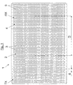
- Fig. 1 schematically shows an antenna system 1 comprising a combination array antenna according to the invention comprising a transmitting phase array antenna 2 comprising a transmitting antenna subarray TX comprising a number Q antenna elements 3 transmitting on a first frequency and a receiving phase array antenna 4 comprising a receiving antenna subarray RX comprising a number P antenna elements 5.
- the transmitting antenna subarray antenna TX is positioned at a centre distance D relative the receiving antenna subarray antenna RX.
- the transmitting antenna subarray antenna TX is arranged to transmit a first signal at a first time period and wherein the receiving antenna subarray antenna RX is arranged to receive the first signal at least partly within the first time period causing a coupling between the transmitting antenna subarray antenna TX and the receiving antenna subarray antenna RX.
- the coupling between the antenna elements in the transmitting antenna subarray antenna TX and the antenna elements in the receiving antenna subarray antenna RX are measured or calculated and the coupling data is stored as a scattering-matrix S BA in a memory and that the scattering matrix S BA is then used in an equation (13) to modify a quiescent excitation x 0 in the transmitting antenna subarray TX in order to get nulls at the elements in receiving antenna subarray RX by controlling the elements in the transmitting antenna subarray antenna (TX) to transmit a signal that nullifies the coupling energy in the receiving antenna subarray antenna RX.
- the calculation is advantageously made by a machine, for example a computer, and the transmitting antenna is controlled by any suitable control means that can control the antenna elements 3 in the transmitting antenna subarray.
- the antenna transmitting antenna subarray TX and the receiving antenna subarray RX are positioned in a combination antenna being essentially flat. However any shape is possible for the antenna transmitting antenna subarray TX and the receiving antenna subarray RX.
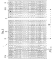
- Fig. 2 schematically shows an antenna system according to the invention comprising a separate transmitting antenna subarray TX and a separate receiving antenna subarray RX facing essentially in the same direction.
- the difference between the system in figure 1 and the system in figure 2 is the relative position of the transmitting antenna subarray TX and the receiving antenna subarray RX.
- the described and below described method could be applied on both system by measuring or calculating the coupling matrix.
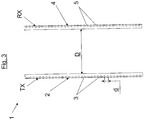
- Fig. 3 schematically shows an antenna system according to the invention comprising a separate transmitting antenna subarray and a separate receiving antenna subarray facing essentially in the opposite directions.
- the difference between the system in figure 1 and the system in figure 3 is the relative position of the transmitting antenna subarray TX and the receiving antenna subarray RX.
- the described and below described method could be applied on both system by measuring or calculating the coupling matrix.
- Fig. 4 schematically shows a flow chart of the method according the invention.
- Box 11 shows that a scattering matrix is created by either measuring the coupling between each element in the transmitting antenna subarray TX and each element in the receiving antenna subarray RX, or by measuring the distance between each element in the transmitting antenna subarray TX and each element in the receiving antenna subarray antenna RX and using knowledge about material and geometrical features of the transmitting antenna subarray TX and the receiving antenna subarray RX, and then calculating the coupling and creating the scattering matrix.
- F 0 be the quiescent pattern transmitting antenna subarray TX obtained when no constraints regarding nulls in receiving antenna subarray RX have been applied
- F 0 ⁇ m ⁇ n x 0 mn e ⁇ jkd mu + nv , where x 0 mn ( x 0 in vector form) is the corresponding excitation.
- F a be the approximate pattern obtained when constraints regarding nulls have been applied
- F a ⁇ m ⁇ n x amn e ⁇ jkd mu + nv , where x amn ( x a in vector form) is the corresponding excitation.
- F a be the closest approximation, in the least mean square sense, to the quiescent pattern F 0 .
- S BA is a P ⁇ Q matrix, where P and Q is the number of elements in receiving antenna subarray RX and transmitting antenna subarray TX respectively.
- Equation (13) shows how to modify the quiescent excitation x 0 in the transmitting antenna subarray TX in order to get nulls at the elements in subarray B.
- Box 13 shows that equation (13) is used to control the elements in the transmitting antenna subarray antenna TX to transmit a signal that nullifies the coupling energy in the receiving antenna subarray antenna RX.
- the transmitting antenna subarray comprises 32 ⁇ 32 elements and where the receiving antenna subarray comprises 16 ⁇ 16 element having subarray coupling, according to the description in connection to any one of figures 1-4 .
- Equation (13) has been applied in order to reduce the coupling between a transmitting antenna subarray TX with 32x32 elements and a receiving antenna subarray antenna RX with 16 ⁇ 16 elements.
- the subarrays are positioned in opposite corners of an array with 80x80 antenna elements (not shown).
- the antenna elements, in both the transmitting antenna subarray TX and the receiving antenna subarray antenna RX, are arranged in a quadratic lattice with element spacing d in both spatial directions.
- the mutual coupling coefficients have been determined from measurements.
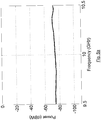
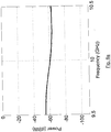
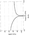
- Figure 5a shows no zeros at the Receiving antenna subarray RX and figure 5b shows zeros at the Receiving antenna subarray RX.
- Equation (13) has been used for the result in figure 5b , but not in figure 5a .
- the excitation according to equation (13) has been determined at the center frequency 10 GHz and has thereafter been used for the whole frequency band.
- Figure 6a shows no zeros at the receiving antenna subarray RX and figure 6b shows zeros at the receiving antenna subarray RX.
- Equation (13) has been used for the result in figure 6b , but not in figure 6a .
- the excitation according to equation (13) has been determined at the center frequency 10 GHz and has thereafter been used for the whole frequency band.
- Figure 7a shows no zeros at the receiving antenna subarray RX and figure 7b shows zeros at the receiving antenna subarray RX.
- Equation (13) has been used for the result in figure 7b , but not in figure 7a .
- the excitation according to equation (13) has been determined at the center frequency 10 GHz and has thereafter been used for the whole frequency band.
- Fig. 8 schematically shows a transmitting antenna subarray TX with fixed position and four different receiving antenna subarray Rx positions relative the transmitting antenna subarray TX.
- the transmitting antenna subarray TX is positioned in one of the corner of the array and the receiving antenna subarray RX is positioned on the array diagonal (passing through the transmitting antenna subarray TX) at four different subarray sub-to-sub centre to centre distances D, being 37d, RX1; 51d, RX2; 65d, RX3; and 79d, RX4, where d is the element spacing.
- the position of the elements or the geometrical features or the material in the transmitting antenna subarray or the receiving antenna subarray are not important per se for the invention but are implicitly taken into consideration during the coupling measurements or must be known when the coupling should be calculated.
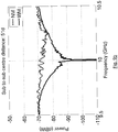
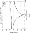
- Figures 9a-9d schematically shows the transmitting antenna subarray TX power coupled to the receiving antenna subarray RX for a 9.5-10.5 GHz frequency band with and without the method according to the invention and for the four different centre distances D in figure 8 .
- Figure 9a shows the result for the sub-to-sub centre distance 37d.
- Figure 9b shows the result for the sub-to-sub centre distance 51d.
- Figure 9c shows the result for the sub-to-sub centre distance 65d.
- Figure 9b shows the result for the sub-to-sub centre distance 79d.
- Figures 9a-9d show the transmitting antenna subarray TX power coupled to the Receiving antenna subarray RX with use of the method according to the invention, i.e. equation (13), shown with the lower continuous line WM in figures 9a-9d and without the use of the method according to the invention shown with the upper continuous line NM in figures 9a-9d .
- the excitation according to equation (13) has been determined at the center frequency 10 GHz and has thereafter been used for the whole frequency band.
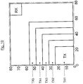
- Figure 10 schematically shows five different sized transmitting antenna subarrays TX and a fixed sized and position of the receiving antenna subarray RX.
- the coupling from transmitting antenna subarrays TX with 24 ⁇ 24, TX1, 32 ⁇ 32, TX2, 40 ⁇ 40, TX3, 48 ⁇ 48, TX4, and 56 ⁇ 56, TX5, elements to a 16 ⁇ 16 element receiving antenna subarray RX is investigated in this section.
- Figure 10 shows that the transmitting antenna subarrays TX are positioned in one of the corner of the array and the receiving antenna subarray RX is positioned at the opposite corner. Observe that the centre distance D between the transmitting antenna subarray TX and the receiving antenna subarray RX decreases with increased transmitting antenna subarray TX size.
- Figures 11a-11e schematically show the coupling of the transmitting antenna subarrays Tx to the receiving antenna subarray RX for the different cases in figure 10 , with the use of the method according to the invention and without the use of the method.
- Figures 11a-11e show the transmitting antenna subarray TX power coupled to the receiving antenna subarray RX with use of the method according to the invention, i.e. equation (13), shown with the lower continuous line WM in figures 11a-11ed and without the use of the method according to the invention shown with the upper continuous line NM in figures 11a-11e .
- the excitation according to equation (13) has been determined at the center frequency 10 GHz and has thereafter been used for the whole frequency band.
- the method according to the invention gives the desired nulling at the Receiving antenna subarray RX with different steering of the transmitting antenna subarray TX and with different sizes and positions of the transmitting antenna subarray TX and receiving antenna subarrays RX.
- the above examples should be used to verify that the inventive method can be used for any antenna system configuration that allows measurement or calculation of the coupling between each antenna element in the transmitting antenna subarray TX and each element in the Receiving antenna subarray RX such that a scattering-matrix can be used in equation (13).
Landscapes
- Engineering & Computer Science (AREA)
- Signal Processing (AREA)
- Computer Networks & Wireless Communication (AREA)
- Variable-Direction Aerials And Aerial Arrays (AREA)
- Radio Transmission System (AREA)
Description
- The invention refers to a method for an antenna system comprising a transmitting phase array antenna comprising a transmitting antenna subarray comprising a number Q antenna elements transmitting on a first frequency and a receiving phase array antenna comprising a receiving antenna subarray comprising a number P antenna elements. The transmitting antenna subarray antenna is positioned at a distance relative the receiving antenna subarray antenna. The transmitting antenna subarray antenna transmits a first signal at a first time period and the receiving antenna subarray antenna receives the first signal at least partly within the first time period causing a coupling between the transmitting antenna subarray antenna and the receiving antenna subarray antenna.
- In today's antenna system comprising a transmitting array antenna and a receiving array antenna, there is coupling between the transmitting antenna and the receiving antenna when they are used at the same time. This is a problem since the transmitting antenna could be too "loud" for a receiving antenna. In prior art the problem with coupling have been solved by introduction of physical obstacles such as walls, etc.
- Coupling between subarrays in an array antenna may constitute a major problem since a transmitting antenna subarray may make another subarray for receive more or less useless because of interference.
- Reduction of the subarray coupling is not an easy task. The large bandwidth of broadband array antennas is a result of strong element coupling.
- The possibility to use existing adaptive beam-forming techniques to reduce the coupling is known in far field pattern, but the previously known technique do not reduce the subarray coupling.
The conclusion is that traditional adaptive beam-forming techniques are not appropriate for reduction of subarray coupling. The document CORCOLES J ET AL: "Mutual Coupling Compensation in Arrays Using a Spherical Wave Expansion of the Radiated Field",IEEE ANTENNAS AND WIRELESS PROPAGATION LETTERS, IEEE, PISCATAWAY, NJ, US, vol. 8, 9 January 2009 (2009-01-09), - 22 April 2009 (2009-04-22), pages 108-111, XP011330904,ISSN: 1536-1225, DOI: 10.1109/LAWP.2008.2012276, discloses a method for an antenna system according to the preamble ofclaim 1. - In view of prior art there still exists a need for an antenna system, comprising a transmitting array antenna and a receiving array antenna, where the mutual coupling between subarrays within a combined transmitting and receiving array antenna or between a transmitting array antenna and a receiving array antenna are nullified or at least reduced. The Invention refers to a method where a transmitting antenna uses adaptive beam-forming functions with a constraint based on the knowledge of coupling between the antenna elements in the transmitting antenna and the receiving antenna, where a scattering matrix between the transmitting antenna and the receiving antenna is used. The scattering matrix comprises a coupling coefficient between each antenna element in the transmitting antenna and each antenna element in the receiving antenna element.
In the description of the invention the transmitting array antenna is described as a transmitting antenna subarray antenna and the receiving antenna is described as a receiving antenna subarray antenna, since the invention refers to an antenna system comprising a transmitting antenna and a receiving antenna regardless of whether if they are comprised in a combination array antenna or whether if they are two separate units.
The scattering matrix is thus used as constraint in an equation to modify a quiescent excitation x 0 in the transmitting antenna subarray antenna in order to get nulls at the elements in the receiving antenna subarray antenna by controlling the elements in the transmitting antenna subarray antenna to transmit a signal that nullifies the coupling energy in the receiving antenna subarray antenna. - Hence, the invention refers to a new method for subarray coupling reduction.
- The invention refers to nullifying transmitted energy from a transmitting antenna in an area connected to a receiving antenna.
- The position of each antenna element in the transmitting antenna subarray antenna relative each element in the receiving antenna subarray antenna is not important per se since according to one example, the coupling can be measured without knowledge of the position in order to create the scattering matrix. However, if the position is changed after the measurement, a new measurement has to be done in order to create a new scattering matrix. Hence, the position must be fixed for each measurement. If the relative position and thus distance is known, it is possible to calculate the scattering matrix. The measurement has the advantage over the calculation that it becomes more precise and that reflections in surrounding structures will be part of the measurement. Both the measurement and the calculation techniques are known from prior art.
- The invention refers to a mathematical algorithm that calculates how the transmitting antenna shall use the apertures in order to create the nullified area(s) in the transmitting pattern at the receiving antenna.
- The method can dynamically shift the nullifying pattern in order to cover different receiving antennas at different points in time.
- A coupling matrix must be determined for use in the algorithm. The coupling matrix can be decided using measurements or calculation. Measurement in situ is preferable since reflections from the surrounding structure will then inherently be part of the coupling matrix.
- The invention can be used on both group antennas of multifunction type and on a number of separated group antennas.
- The invention has the following advantages:
- The method gives a better performance of an already existing group antenna used for both transmitting and receiving.
- The method is forceful and simple to implement since there is only calculations on already existing devices.
- The method has very little impact on the radiation diagram of the transmitting antenna.
- No extra hardware is needed. The already existing functions, in the group antenna, regarding control of amplitude and phase are used. The control of amplitude and phase for the different elements in the antenna system for beam forming purposes is well known in the prior art.
- The method gives increased antenna performance.
- The method gives increased field of application of array antennas.
- The invention can be used in all type of phased array antennas where the coupling between subarrays within multifunction array antennas or between array antennas needs to be reduced
- The invention relies on the possibility to detect or calculate the coupling between the subarray of the transmitting antenna and the subarray of the receiving antenna and to use the scattering matrix between the subarrays as a constraint with an antenna pattern synthesis method, in order to reduce the coupling. A constraint with the least mean square pattern synthesis method is used in the invention.
- One example on how to use the constraint is the least mean square pattern synthesis method as described below, but other solutions could be possible with another method for solving a problem aiming to modify the quiescent excitation in the transmitting antenna subarray in order to get nulls at the elements in the receiving antenna subarray.
- In order to explain the invention further an example will be described below where the antenna system is one of many possibilities, but where the calculations can be used on all the possible antenna system referring to the invention, i.e. a transmitting array antenna and a receiving array antenna where the coupling from the transmitting antenna to the receiving antenna needs to be reduced.
- The example refers to an array where the antenna elements are arranged in a planar rectangular lattice with element spacing d in both spatial directions and is used in the derivation of the method according to the invention. The final result that shows how to modify the array excitation coefficients is valid for any type of planar or non-planar array lattice.
- Assume that a transmitting antenna subarray TX is used as a transmitting antenna and that a receiving antenna subarray RX is used as the receiving antenna. The goal is to reduce the coupling from the transmitting antenna subarray TX to the receiving antenna subarray RX with as little effect as possible on the transmitting antenna subarray TX far-field pattern. The transmitting antenna subarray TX far-field pattern is described by the array factor

- Where xmn (x in vector form) is the complex excitation of element (m, n) in transmitting antenna subarray TX, d is the element spacing, k is the wavenumber, λ is the wavelength and (θ,ϕ) is the direction in space in spherical coordinates. The array normal direction is given by θ=0 degrees. Let F 0 be the quiescent pattern of the transmitting antenna subarray obtained when no constraints regarding nulls in receiving antenna subarray RX have been applied

- Let Fa be the approximate pattern obtained when constraints regarding nulls have been applied

- The coupling, b, from the elements in transmitting antenna subarray TX to the elements in receiving antenna subarray RX is

- The synthesis problem can then be stated as: find the approximate pattern Fa such that the mean square difference


- Parseval's identity on equation (5) gives

- Where the horizontal bar symbol denote complex conjugate. Superscript T denotes transpose. Parseval's identity is known per se in prior art.
- The synthesis problem now becomes


- The solution to this optimization problem can be obtained by using "Lagrange's multipliers"


β is determined from equation (9) and (11)
- Substitution of equation (12) in equation (11) finally gives

- Some of the properties of the method according to the invention are:
- It is used on the transmitting antenna subarray TX. The only information needed in order to use the method is the scattering matrix between the transmitting antenna subarray TX and the receiving antenna subarrays RX. Information about the excitation of the receiving antenna subarray RX is not needed. Since the method is used on the transmitting antenna subarray TX it does not affect beam-forming on the receiving antenna subarray RX.
- The term between the parentheses on the right hand side of equation (13) is independent of the array antenna scan direction and needs to be calculated only once for each frequency. The frequency independency is true if the coupling coefficients between the elements in the transmitting antenna subarray TX and the receiving antenna subarray RX do not change with time.
- The best way to determine the coupling coefficients from the transmitting antenna subarray TX to the receiving antenna subarray RX is probably to measure them when the array has been integrated since the coupling to the environment (radome etc) close to the array then will be included in the coupling coefficients. It may be possible to use the calibration function, if any, in the array to determine the coupling coefficients.
- If the number of elements in the transmitting antenna subarray TX and receiving antenna subarray RX is Q and P respectively then P < Q is a necessary condition since the number of free variables is Q.
- The invention will below be described in connection to a number of drawings, in which:
-
Fig. 1 schematically shows an antenna system comprising a combination array antenna according to the invention comprising a transmitting antenna subarray and a receiving antenna subarray; -
Fig. 2 schematically shows an antenna system according to the invention comprising a separate transmitting antenna subarray and a separate receiving antenna subarray facing essentially in the same direction; -
Fig. 3 schematically shows an antenna system according to the invention comprising a separate transmitting antenna subarray and a separate receiving antenna subarray facing essentially in the opposite directions; -
Fig. 4 schematically shows a flow chart of the method according the invention; -
Figs. 5a and5b show the power coupling from the transmitting antenna subarray TX and receiving antenna subarrays RX over a 1 GHz frequency band at 10 GHz for the transmitting antenna subarray TX scan direction (θ0 , ϕ0 )=(0°,0°), without the use of the inventive method and with the use of the inventive method respectively; -
Fig. 6a and6b show the power coupling from the transmitting antenna subarray TX and receiving antenna subarrays RX over a 1 GHz frequency band at 10 GHz for the transmitting antenna subarray TX scan direction (θ0 , ϕ0 )=(60°,45°), without the use of the inventive method and with the use of the inventive method respectively; -
Fig. 7a and7b schematically show the power coupling from the transmitting antenna subarray TX to the receiving antenna subarray RX over a 1 GHz frequency band at 10 GHz for the transmitting antenna subarray TX scan direction (θ0 , ϕ0 )=(60°,225°), without the use of the inventive method and with the use of the inventive method respectively; -
Fig. 8 schematically shows a transmitting antenna subarray TX with fixed position and four different receiving antenna subarray Rx positions; -
Figs 9a-9d schematically show the transmitting antenna subarray TX power coupled to the Receiving antenna subarray RX for a 9.5-10.5 GHz frequency band with and without the method according to the invention and for the four different antenna subarray Rx positions infigure 8 ; -
Fig. 10 schematically shows five different sized transmitting antenna subarrays TX relative a receiving antenna subarray Rx with fixed size, and in which; -
Figs. 11a-11e schematically show the coupling of the transmitting antenna subarrays Tx to the receiving antenna subarray RX for the different cases infigure 10 , with the use of the method according to the invention and without the use of the method. -
Fig. 1 schematically shows anantenna system 1 comprising a combination array antenna according to the invention comprising a transmittingphase array antenna 2 comprising a transmitting antenna subarray TX comprising a numberQ antenna elements 3 transmitting on a first frequency and a receivingphase array antenna 4 comprising a receiving antenna subarray RX comprising a numberP antenna elements 5. The transmitting antenna subarray antenna TX is positioned at a centre distance D relative the receiving antenna subarray antenna RX. The transmitting antenna subarray antenna TX is arranged to transmit a first signal at a first time period and wherein the receiving antenna subarray antenna RX is arranged to receive the first signal at least partly within the first time period causing a coupling between the transmitting antenna subarray antenna TX and the receiving antenna subarray antenna RX. - The coupling between the antenna elements in the transmitting antenna subarray antenna TX and the antenna elements in the receiving antenna subarray antenna RX are measured or calculated and the coupling data is stored as a scattering-matrix SBA in a memory and that the scattering matrix SBA is then used in an equation (13) to modify a quiescent excitation x 0 in the transmitting antenna subarray TX in order to get nulls at the elements in receiving antenna subarray RX by controlling the elements in the transmitting antenna subarray antenna (TX) to transmit a signal that nullifies the coupling energy in the receiving antenna subarray antenna RX. The calculation is advantageously made by a machine, for example a computer, and the transmitting antenna is controlled by any suitable control means that can control the
antenna elements 3 in the transmitting antenna subarray. - In
figure 1 the antenna transmitting antenna subarray TX and the receiving antenna subarray RX are positioned in a combination antenna being essentially flat. However any shape is possible for the antenna transmitting antenna subarray TX and the receiving antenna subarray RX. -
Fig. 2 schematically shows an antenna system according to the invention comprising a separate transmitting antenna subarray TX and a separate receiving antenna subarray RX facing essentially in the same direction. The difference between the system infigure 1 and the system infigure 2 is the relative position of the transmitting antenna subarray TX and the receiving antenna subarray RX. The described and below described method could be applied on both system by measuring or calculating the coupling matrix. -
Fig. 3 schematically shows an antenna system according to the invention comprising a separate transmitting antenna subarray and a separate receiving antenna subarray facing essentially in the opposite directions. The difference between the system infigure 1 and the system infigure 3 is the relative position of the transmitting antenna subarray TX and the receiving antenna subarray RX. The described and below described method could be applied on both system by measuring or calculating the coupling matrix. -
Fig. 4 schematically shows a flow chart of the method according the invention. -
Box 11 shows that a scattering matrix is created by either measuring the coupling between each element in the transmitting antenna subarray TX and each element in the receiving antenna subarray RX, or by measuring the distance between each element in the transmitting antenna subarray TX and each element in the receiving antenna subarray antenna RX and using knowledge about material and geometrical features of the transmitting antenna subarray TX and the receiving antenna subarray RX, and then calculating the coupling and creating the scattering matrix. -
Box 12 shows that the following calculations are made: - a modification of a quiescent excitation x 0 in transmitting antenna subarray TX is calculated by the following steps:
- a transmitting antenna subarray TX far-field pattern is described by the array factor

- a transmitting antenna subarray TX far-field pattern is described by the array factor
- Let F 0 be the quiescent pattern transmitting antenna subarray TX obtained when no constraints regarding nulls in receiving antenna subarray RX have been applied

- Let Fa be the approximate pattern obtained when constraints regarding nulls have been applied

- The coupling, b, from the elements in transmitting antenna subarray TX to the elements in receiving antenna subarray RX is

- The synthesis problem can then be stated as: find the approximate pattern Fa such that the mean square difference


- Parseval's identity on equation (5) gives

- Where the horizontal bar symbol denote complex conjugate. Superscript T denotes transpose.
- The synthesis problem now becomes


- The solution to this optimization problem can be obtained by using "Lagrange's multipliers"

- The solution to this optimization problem is unequivocal and can be obtained by using the above described "Lagrange's multipliers" or any other suitable technique.
where β is a complex vector to be determined. Element index m, n has for simplicity been replaced by the single index i, j is the receiving antenna subarray RX element index. Substitution of equation (8) and equation (9) in equation (10) gives
β is determined from equation (9) and (11)
- Substitution of equation (12) in equation (11) finally gives

-
Box 13 shows that equation (13) is used to control the elements in the transmitting antenna subarray antenna TX to transmit a signal that nullifies the coupling energy in the receiving antenna subarray antenna RX. - Below follows a numerical example where the transmitting antenna subarray comprises 32×32 elements and where the receiving antenna subarray comprises 16×16 element having subarray coupling, according to the description in connection to any one of
figures 1-4 . - Equation (13) has been applied in order to reduce the coupling between a transmitting antenna subarray TX with 32x32 elements and a receiving antenna subarray antenna RX with 16×16 elements. The subarrays are positioned in opposite corners of an array with 80x80 antenna elements (not shown). The antenna elements, in both the transmitting antenna subarray TX and the receiving antenna subarray antenna RX, are arranged in a quadratic lattice with element spacing d in both spatial directions. The mutual coupling coefficients have been determined from measurements. The transmitting antenna subarray antenna TX have a uniform taper and is steered to three different directions (θ0 ,ϕ0 )=(0°,0°), (60°,45°) (i.e. toward the receiving antenna subarray RX) and (60°,225°) (i.e. away from the Receiving antenna subarray RX), by way of conventional methods.
-
Figures 5a and5b show the power coupling from the transmitting antenna subarray TX to the Receiving antenna subarray RX over a 1 GHz frequency band at 10 GHz for the transmitting antenna subarray TX scan direction (θ0 ,ϕ0 )=(0°,0°).Figure 5a shows no zeros at the Receiving antenna subarray RX andfigure 5b shows zeros at the Receiving antenna subarray RX. Equation (13) has been used for the result infigure 5b , but not infigure 5a . The excitation according to equation (13) has been determined at thecenter frequency 10 GHz and has thereafter been used for the whole frequency band. -
Figures 6a and6b show the power coupling from the transmitting antenna subarray antenna TX to the receiving antenna subarray RX over a 1 GHz frequency band at 10 GHz for the transmitting antenna subarray TX scan direction θ0 ,ϕ0 =60°,45°, i.e. toward the receiving antenna subarray RX.Figure 6a shows no zeros at the receiving antenna subarray RX andfigure 6b shows zeros at the receiving antenna subarray RX. Equation (13) has been used for the result infigure 6b , but not infigure 6a . The excitation according to equation (13) has been determined at thecenter frequency 10 GHz and has thereafter been used for the whole frequency band. -
Figures 7a and7b show the power coupling from the transmitting antenna TX to the Receiving antenna subarray RX over a 1 GHz frequency band at 10 GHz for the transmitting antenna subarray TX scan direction (θ0 ,ϕ0 )=60°,225°, i.e. away from the receiving antenna subarray RX.Figure 7a shows no zeros at the receiving antenna subarray RX andfigure 7b shows zeros at the receiving antenna subarray RX. Equation (13) has been used for the result infigure 7b , but not infigure 7a . The excitation according to equation (13) has been determined at thecenter frequency 10 GHz and has thereafter been used for the whole frequency band. - The dependency on some parameters in the new method for subarray to subarray coupling reduction is investigated in this section. The same 80×80 element array as in the previous section is used.
- The coupling from a 32×32 element transmitting antenna subarray TX to a 16×16 element receiving antenna subarray RX for four different spacing between the subarrays is investigated in this section.
-
Fig. 8 schematically shows a transmitting antenna subarray TX with fixed position and four different receiving antenna subarray Rx positions relative the transmitting antenna subarray TX. The transmitting antenna subarray TX is positioned in one of the corner of the array and the receiving antenna subarray RX is positioned on the array diagonal (passing through the transmitting antenna subarray TX) at four different subarray sub-to-sub centre to centre distances D, being 37d, RX1; 51d, RX2; 65d, RX3; and 79d, RX4, where d is the element spacing. The transmitting antenna subarray TX has a uniform taper and is steered to (θ0 ,ϕ0 )=(0°,0°). - The position of the elements or the geometrical features or the material in the transmitting antenna subarray or the receiving antenna subarray are not important per se for the invention but are implicitly taken into consideration during the coupling measurements or must be known when the coupling should be calculated.
-
Figures 9a-9d schematically shows the transmitting antenna subarray TX power coupled to the receiving antenna subarray RX for a 9.5-10.5 GHz frequency band with and without the method according to the invention and for the four different centre distances D infigure 8 .Figure 9a shows the result for the sub-to-sub centre distance 37d.Figure 9b shows the result for the sub-to-sub centre distance 51d.Figure 9c shows the result for the sub-to-sub centre distance 65d.Figure 9b shows the result for the sub-to-sub centre distance 79d. -
Figures 9a-9d show the transmitting antenna subarray TX power coupled to the Receiving antenna subarray RX with use of the method according to the invention, i.e. equation (13), shown with the lower continuous line WM infigures 9a-9d and without the use of the method according to the invention shown with the upper continuous line NM infigures 9a-9d . The excitation according to equation (13) has been determined at thecenter frequency 10 GHz and has thereafter been used for the whole frequency band. -
Figure 10 schematically shows five different sized transmitting antenna subarrays TX and a fixed sized and position of the receiving antenna subarray RX. The coupling from transmitting antenna subarrays TX with 24×24, TX1, 32×32, TX2, 40×40, TX3, 48×48, TX4, and 56×56, TX5, elements to a 16×16 element receiving antenna subarray RX is investigated in this section.Figure 10 shows that the transmitting antenna subarrays TX are positioned in one of the corner of the array and the receiving antenna subarray RX is positioned at the opposite corner. Observe that the centre distance D between the transmitting antenna subarray TX and the receiving antenna subarray RX decreases with increased transmitting antenna subarray TX size. The transmitting antenna subarrays TX have uniform taper and are steered to (θ0 ,ϕ0 )=(0°,0°). -
Figures 11a-11e schematically show the coupling of the transmitting antenna subarrays Tx to the receiving antenna subarray RX for the different cases infigure 10 , with the use of the method according to the invention and without the use of the method. -
Figures 11a-11e show the result of the subarray to subarray coupling for the five different transmitting antenna subarray TX sizes with the transmitting antenna subarray TX steered to (θ0 ,ϕ0 )=(0°,0°).). -
Figures 11a-11e show the transmitting antenna subarray TX power coupled to the receiving antenna subarray RX with use of the method according to the invention, i.e. equation (13), shown with the lower continuous line WM infigures 11a-11ed and without the use of the method according to the invention shown with the upper continuous line NM infigures 11a-11e . The excitation according to equation (13) has been determined at thecenter frequency 10 GHz and has thereafter been used for the whole frequency band. - From
figures 1-11 it becomes clear that the method according to the invention gives the desired nulling at the Receiving antenna subarray RX with different steering of the transmitting antenna subarray TX and with different sizes and positions of the transmitting antenna subarray TX and receiving antenna subarrays RX. Hence, the above examples should be used to verify that the inventive method can be used for any antenna system configuration that allows measurement or calculation of the coupling between each antenna element in the transmitting antenna subarray TX and each element in the Receiving antenna subarray RX such that a scattering-matrix can be used in equation (13).
Claims (5)
- A method for an antenna system (1) comprising a transmitting phase array antenna (2) comprising a transmitting antenna subarray (TX) comprising a number Q antenna elements (3) transmitting on a first frequency and a receiving phase array antenna (4) comprising a receiving antenna subarray (RX) comprising a number P antenna elements (5), the transmitting antenna subarray (TX) being positioned at a distance (D) relative the receiving antenna subarray (RX), wherein the transmitting antenna subarray (TX) transmits a first signal at a first time period and wherein the receiving antenna subarray (RX) receives the first signal at least partly within the first time period causing a coupling between the transmitting antenna subarray (TX) and the receiving antenna subarray (RX), characterized in that the coupling between the antenna elements in the transmitting antenna subarray (TX) and the antenna elements in the receiving antenna subarray (RX) are decided in a scattering-matrix SBA and that the scattering matrix SBA is used as a constraint in order to modify a quiescent excitation x 0 in the transmitting antenna subarray (TX) in order to get nulls at the elements (5) in the receiving antenna subarray (RX) by controlling the elements (3) in the transmitting antenna subarray (TX) to transmit a signal x a that nullifies the coupling energy in the receiving antenna subarray (RX), wherein the relation between the signal x a and the quiescent excitation x0 is

- A method according to claim 1, wherein Q is greater than P.
- A method according to any one of claims 1 or 2, wherein the coupling is decided by transmitting on one antenna element (3) at a time in the transmitting antenna subarray (TX) and receiving the signal on one antenna element (5) at a time for every transmission of the antenna element (3) in the transmitting antenna subarray (TX), and wherein the transmitted signal is measured in the receiving antenna subarray (RX) giving the scattering matrix SBA, comprising Q times P measurements representing the coupling.
- A method according to any one of claims 1-2, wherein the coupling is decided by a numerical calculation by use of data regarding the distance from each element (3) in the transmitting antenna subarray (TX) to each element (5) in the receiving antenna subarray (RX) and data regarding material and shape of the transmitting antenna subarray (TX) and the receiving antenna subarray (RX).
- A method according to any one of the preceding claims, wherein a modification of the quiescent excitation x 0 in transmitting antenna subarray (TX) is calculated by the following steps:a transmitting antenna subarray (TX) far-field pattern is described by the array factor

Let F 0 be the quiescent pattern of the transmitting antenna subarray (TX) obtained when no constraints regarding nulls in the receiving antenna subarray (RX) have been applied
Let Fa be the approximate pattern obtained when constraints regarding nulls have been applied
The coupling, b, from the elements in transmitting antenna subarray (TX) to the elements in receiving antenna subarray (RX) is
The synthesis problem can then be stated as: find the approximate pattern Fa such that the mean square difference


The synthesis problem now becomes


β is determined from equation (9) and (11)

Applications Claiming Priority (1)
| Application Number | Priority Date | Filing Date | Title |
|---|---|---|---|
| PCT/SE2009/051338 WO2011065876A1 (en) | 2009-11-25 | 2009-11-25 | Array antenna system |
Publications (3)
| Publication Number | Publication Date |
|---|---|
| EP2504927A1 EP2504927A1 (en) | 2012-10-03 |
| EP2504927A4 EP2504927A4 (en) | 2015-08-26 |
| EP2504927B1 true EP2504927B1 (en) | 2018-04-18 |
Family
ID=44066765
Family Applications (1)
| Application Number | Title | Priority Date | Filing Date |
|---|---|---|---|
| EP09851731.1A Active EP2504927B1 (en) | 2009-11-25 | 2009-11-25 | Array antenna system |
Country Status (5)
| Country | Link |
|---|---|
| US (1) | US8731483B2 (en) |
| EP (1) | EP2504927B1 (en) |
| KR (1) | KR101633841B1 (en) |
| IL (1) | IL219536A (en) |
| WO (1) | WO2011065876A1 (en) |
Families Citing this family (9)
| Publication number | Priority date | Publication date | Assignee | Title |
|---|---|---|---|---|
| TWI528638B (en) * | 2014-05-08 | 2016-04-01 | 啟碁科技股份有限公司 | Radio-frequency system |
| US9749031B2 (en) | 2015-04-08 | 2017-08-29 | Blackberry Limited | Mutual coupling mitigation in a multi-port antenna system |
| CN106329151B (en) * | 2015-06-30 | 2019-10-22 | 华为技术有限公司 | A kind of antenna array and network equipment |
| TWI582451B (en) * | 2016-06-15 | 2017-05-11 | 啟碁科技股份有限公司 | Vehicular radar system |
| CN106099395A (en) * | 2016-08-11 | 2016-11-09 | 成都雷电微力科技有限公司 | A kind of multifrequency Shared aperture is combined phased array antenna structure |
| US10498415B2 (en) * | 2016-12-20 | 2019-12-03 | Raytheon Company | Systems and methods for a multi-mode active electronically scanned array |
| CN110598247B (en) * | 2019-08-01 | 2020-10-27 | 中国电子科技集团公司第二十九研究所 | Phased array time-frequency mixed phase matching design method based on subarray division |
| CN112768955B (en) * | 2021-01-04 | 2022-12-13 | 上海航天测控通信研究所 | Anti-aliasing rotation dislocation array antenna |
| US12394891B2 (en) * | 2023-09-13 | 2025-08-19 | L3Harris Technologies, Inc. | Phase array antenna system and phase array antenna for improved transmission and reception isolation |
Family Cites Families (5)
| Publication number | Priority date | Publication date | Assignee | Title |
|---|---|---|---|---|
| GB0125178D0 (en) * | 2001-10-19 | 2001-12-12 | Koninkl Philips Electronics Nv | Method of operating a wireless communication system |
| US7362266B2 (en) * | 2004-12-07 | 2008-04-22 | Lockheed Martin Corporation | Mutual coupling method for calibrating a phased array |
| US20090117859A1 (en) * | 2006-04-07 | 2009-05-07 | Belair Networks Inc. | System and method for frequency offsetting of information communicated in mimo based wireless networks |
| US7941194B2 (en) * | 2007-11-16 | 2011-05-10 | Silicon Laboratories Inc. | Antenna co-location in portable devices for simultaneous receive and transmit |
| US8055216B2 (en) * | 2009-03-27 | 2011-11-08 | Sony Ericsson Mobile Communications Ab | Antenna matching for MIMO transceivers |
-
2009
- 2009-11-25 WO PCT/SE2009/051338 patent/WO2011065876A1/en not_active Ceased
- 2009-11-25 EP EP09851731.1A patent/EP2504927B1/en active Active
- 2009-11-25 US US13/511,901 patent/US8731483B2/en active Active
- 2009-11-25 KR KR1020127014959A patent/KR101633841B1/en active Active
-
2012
- 2012-05-02 IL IL219536A patent/IL219536A/en active IP Right Grant
Non-Patent Citations (1)
| Title |
|---|
| None * |
Also Published As
| Publication number | Publication date |
|---|---|
| IL219536A0 (en) | 2012-06-28 |
| WO2011065876A1 (en) | 2011-06-03 |
| IL219536A (en) | 2016-04-21 |
| KR20120103626A (en) | 2012-09-19 |
| EP2504927A4 (en) | 2015-08-26 |
| KR101633841B1 (en) | 2016-06-27 |
| US8731483B2 (en) | 2014-05-20 |
| US20120289172A1 (en) | 2012-11-15 |
| EP2504927A1 (en) | 2012-10-03 |
Similar Documents
| Publication | Publication Date | Title |
|---|---|---|
| US8731483B2 (en) | Array antenna system | |
| JP6883592B2 (en) | Polarization phased array radar system and its operation method | |
| JP7306573B2 (en) | RADAR DEVICE, VEHICLE AND POSITION DETECTION DEVICE INCLUDING THE SAME | |
| CA2630379A1 (en) | Frequency scanning antenna | |
| CN102567574B (en) | Layout optimizing method for phased-array antennas on large-scale ship plane | |
| CN105785328A (en) | Subarray-division-based FDA distance-angle decoupling wave beam formation method | |
| CN106886619A (en) | Phased array antenna front comprehensive realization method | |
| JP7439577B2 (en) | Radar device calibration device, calibration system, calibration method, and radar device | |
| US7446728B2 (en) | Method and apparatus for constructing general wireless antenna systems | |
| Schaubert et al. | The square kilometer array (SKA) antenna | |
| KR101470581B1 (en) | Array antenna and array antenna of radar detection system | |
| Schvartzman et al. | Pattern synthesis and digital beamforming capabilities of the fully digital horus radar | |
| US9372258B2 (en) | Method for electromagnetically characterizing a target | |
| CN113569192B (en) | A multi-phase hierarchical nested array antenna beam synthesis method | |
| JP2009076986A (en) | Microstrip array antenna and phase monopulse radar device | |
| EP1932212B1 (en) | Frequency scanning antenna | |
| Zhu et al. | Pattern performance of active phased array antenna for Gaofen-3 satellite | |
| Belfiori et al. | Coherent MIMO array design with periodical physical element structures | |
| Henault | OTHR phase-only beamformer drone-based measurements | |
| Don et al. | Dual-Polarised Digital Phased Array Antenna for Millimeter-Wave Beam Steering Applications | |
| CN118777990B (en) | Electromagnetic metamaterial-based array radar space-time coding digital regulation anti-interference method | |
| EP4601120A1 (en) | Beam-steerable antenna arrangement | |
| Palianytsia et al. | Computer simulation of ultrawideband Vivaldi active phased array antenna | |
| CN105929372A (en) | Multi narrow wave beam shaping method and device for MIMO radar | |
| EP3361649B1 (en) | Low-complexity beam selection method |
Legal Events
| Date | Code | Title | Description |
|---|---|---|---|
| PUAI | Public reference made under article 153(3) epc to a published international application that has entered the european phase |
Free format text: ORIGINAL CODE: 0009012 |
|
| 17P | Request for examination filed |
Effective date: 20120521 |
|
| AK | Designated contracting states |
Kind code of ref document: A1 Designated state(s): AT BE BG CH CY CZ DE DK EE ES FI FR GB GR HR HU IE IS IT LI LT LU LV MC MK MT NL NO PL PT RO SE SI SK SM TR |
|
| DAX | Request for extension of the european patent (deleted) | ||
| RA4 | Supplementary search report drawn up and despatched (corrected) |
Effective date: 20150728 |
|
| RIC1 | Information provided on ipc code assigned before grant |
Ipc: H01Q 21/00 20060101ALI20150722BHEP Ipc: H01Q 3/26 20060101ALI20150722BHEP Ipc: H04B 1/38 20150101AFI20150722BHEP Ipc: H01Q 21/06 20060101ALI20150722BHEP Ipc: H01Q 1/52 20060101ALI20150722BHEP |
|
| GRAP | Despatch of communication of intention to grant a patent |
Free format text: ORIGINAL CODE: EPIDOSNIGR1 |
|
| STAA | Information on the status of an ep patent application or granted ep patent |
Free format text: STATUS: GRANT OF PATENT IS INTENDED |
|
| INTG | Intention to grant announced |
Effective date: 20171130 |
|
| GRAS | Grant fee paid |
Free format text: ORIGINAL CODE: EPIDOSNIGR3 |
|
| GRAA | (expected) grant |
Free format text: ORIGINAL CODE: 0009210 |
|
| STAA | Information on the status of an ep patent application or granted ep patent |
Free format text: STATUS: THE PATENT HAS BEEN GRANTED |
|
| AK | Designated contracting states |
Kind code of ref document: B1 Designated state(s): AT BE BG CH CY CZ DE DK EE ES FI FR GB GR HR HU IE IS IT LI LT LU LV MC MK MT NL NO PL PT RO SE SI SK SM TR |
|
| REG | Reference to a national code |
Ref country code: GB Ref legal event code: FG4D |
|
| REG | Reference to a national code |
Ref country code: CH Ref legal event code: EP |
|
| REG | Reference to a national code |
Ref country code: AT Ref legal event code: REF Ref document number: 991504 Country of ref document: AT Kind code of ref document: T Effective date: 20180515 |
|
| REG | Reference to a national code |
Ref country code: IE Ref legal event code: FG4D |
|
| REG | Reference to a national code |
Ref country code: DE Ref legal event code: R096 Ref document number: 602009051917 Country of ref document: DE |
|
| REG | Reference to a national code |
Ref country code: NL Ref legal event code: FP |
|
| REG | Reference to a national code |
Ref country code: LT Ref legal event code: MG4D |
|
| PG25 | Lapsed in a contracting state [announced via postgrant information from national office to epo] |
Ref country code: BG Free format text: LAPSE BECAUSE OF FAILURE TO SUBMIT A TRANSLATION OF THE DESCRIPTION OR TO PAY THE FEE WITHIN THE PRESCRIBED TIME-LIMIT Effective date: 20180718 Ref country code: NO Free format text: LAPSE BECAUSE OF FAILURE TO SUBMIT A TRANSLATION OF THE DESCRIPTION OR TO PAY THE FEE WITHIN THE PRESCRIBED TIME-LIMIT Effective date: 20180718 Ref country code: FI Free format text: LAPSE BECAUSE OF FAILURE TO SUBMIT A TRANSLATION OF THE DESCRIPTION OR TO PAY THE FEE WITHIN THE PRESCRIBED TIME-LIMIT Effective date: 20180418 Ref country code: SE Free format text: LAPSE BECAUSE OF FAILURE TO SUBMIT A TRANSLATION OF THE DESCRIPTION OR TO PAY THE FEE WITHIN THE PRESCRIBED TIME-LIMIT Effective date: 20180418 Ref country code: ES Free format text: LAPSE BECAUSE OF FAILURE TO SUBMIT A TRANSLATION OF THE DESCRIPTION OR TO PAY THE FEE WITHIN THE PRESCRIBED TIME-LIMIT Effective date: 20180418 Ref country code: LT Free format text: LAPSE BECAUSE OF FAILURE TO SUBMIT A TRANSLATION OF THE DESCRIPTION OR TO PAY THE FEE WITHIN THE PRESCRIBED TIME-LIMIT Effective date: 20180418 Ref country code: PL Free format text: LAPSE BECAUSE OF FAILURE TO SUBMIT A TRANSLATION OF THE DESCRIPTION OR TO PAY THE FEE WITHIN THE PRESCRIBED TIME-LIMIT Effective date: 20180418 |
|
| PG25 | Lapsed in a contracting state [announced via postgrant information from national office to epo] |
Ref country code: LV Free format text: LAPSE BECAUSE OF FAILURE TO SUBMIT A TRANSLATION OF THE DESCRIPTION OR TO PAY THE FEE WITHIN THE PRESCRIBED TIME-LIMIT Effective date: 20180418 Ref country code: GR Free format text: LAPSE BECAUSE OF FAILURE TO SUBMIT A TRANSLATION OF THE DESCRIPTION OR TO PAY THE FEE WITHIN THE PRESCRIBED TIME-LIMIT Effective date: 20180719 Ref country code: HR Free format text: LAPSE BECAUSE OF FAILURE TO SUBMIT A TRANSLATION OF THE DESCRIPTION OR TO PAY THE FEE WITHIN THE PRESCRIBED TIME-LIMIT Effective date: 20180418 |
|
| REG | Reference to a national code |
Ref country code: AT Ref legal event code: MK05 Ref document number: 991504 Country of ref document: AT Kind code of ref document: T Effective date: 20180418 |
|
| PG25 | Lapsed in a contracting state [announced via postgrant information from national office to epo] |
Ref country code: PT Free format text: LAPSE BECAUSE OF FAILURE TO SUBMIT A TRANSLATION OF THE DESCRIPTION OR TO PAY THE FEE WITHIN THE PRESCRIBED TIME-LIMIT Effective date: 20180820 |
|
| REG | Reference to a national code |
Ref country code: DE Ref legal event code: R097 Ref document number: 602009051917 Country of ref document: DE |
|
| PG25 | Lapsed in a contracting state [announced via postgrant information from national office to epo] |
Ref country code: EE Free format text: LAPSE BECAUSE OF FAILURE TO SUBMIT A TRANSLATION OF THE DESCRIPTION OR TO PAY THE FEE WITHIN THE PRESCRIBED TIME-LIMIT Effective date: 20180418 Ref country code: AT Free format text: LAPSE BECAUSE OF FAILURE TO SUBMIT A TRANSLATION OF THE DESCRIPTION OR TO PAY THE FEE WITHIN THE PRESCRIBED TIME-LIMIT Effective date: 20180418 Ref country code: RO Free format text: LAPSE BECAUSE OF FAILURE TO SUBMIT A TRANSLATION OF THE DESCRIPTION OR TO PAY THE FEE WITHIN THE PRESCRIBED TIME-LIMIT Effective date: 20180418 Ref country code: CZ Free format text: LAPSE BECAUSE OF FAILURE TO SUBMIT A TRANSLATION OF THE DESCRIPTION OR TO PAY THE FEE WITHIN THE PRESCRIBED TIME-LIMIT Effective date: 20180418 Ref country code: SK Free format text: LAPSE BECAUSE OF FAILURE TO SUBMIT A TRANSLATION OF THE DESCRIPTION OR TO PAY THE FEE WITHIN THE PRESCRIBED TIME-LIMIT Effective date: 20180418 Ref country code: DK Free format text: LAPSE BECAUSE OF FAILURE TO SUBMIT A TRANSLATION OF THE DESCRIPTION OR TO PAY THE FEE WITHIN THE PRESCRIBED TIME-LIMIT Effective date: 20180418 |
|
| PLBE | No opposition filed within time limit |
Free format text: ORIGINAL CODE: 0009261 |
|
| STAA | Information on the status of an ep patent application or granted ep patent |
Free format text: STATUS: NO OPPOSITION FILED WITHIN TIME LIMIT |
|
| PG25 | Lapsed in a contracting state [announced via postgrant information from national office to epo] |
Ref country code: SM Free format text: LAPSE BECAUSE OF FAILURE TO SUBMIT A TRANSLATION OF THE DESCRIPTION OR TO PAY THE FEE WITHIN THE PRESCRIBED TIME-LIMIT Effective date: 20180418 |
|
| 26N | No opposition filed |
Effective date: 20190121 |
|
| PG25 | Lapsed in a contracting state [announced via postgrant information from national office to epo] |
Ref country code: SI Free format text: LAPSE BECAUSE OF FAILURE TO SUBMIT A TRANSLATION OF THE DESCRIPTION OR TO PAY THE FEE WITHIN THE PRESCRIBED TIME-LIMIT Effective date: 20180418 |
|
| REG | Reference to a national code |
Ref country code: CH Ref legal event code: PL |
|
| PG25 | Lapsed in a contracting state [announced via postgrant information from national office to epo] |
Ref country code: MC Free format text: LAPSE BECAUSE OF FAILURE TO SUBMIT A TRANSLATION OF THE DESCRIPTION OR TO PAY THE FEE WITHIN THE PRESCRIBED TIME-LIMIT Effective date: 20180418 Ref country code: LU Free format text: LAPSE BECAUSE OF NON-PAYMENT OF DUE FEES Effective date: 20181125 |
|
| REG | Reference to a national code |
Ref country code: BE Ref legal event code: MM Effective date: 20181130 |
|
| REG | Reference to a national code |
Ref country code: IE Ref legal event code: MM4A |
|
| PG25 | Lapsed in a contracting state [announced via postgrant information from national office to epo] |
Ref country code: LI Free format text: LAPSE BECAUSE OF NON-PAYMENT OF DUE FEES Effective date: 20181130 Ref country code: CH Free format text: LAPSE BECAUSE OF NON-PAYMENT OF DUE FEES Effective date: 20181130 |
|
| PG25 | Lapsed in a contracting state [announced via postgrant information from national office to epo] |
Ref country code: IE Free format text: LAPSE BECAUSE OF NON-PAYMENT OF DUE FEES Effective date: 20181125 |
|
| PG25 | Lapsed in a contracting state [announced via postgrant information from national office to epo] |
Ref country code: BE Free format text: LAPSE BECAUSE OF NON-PAYMENT OF DUE FEES Effective date: 20181130 |
|
| PG25 | Lapsed in a contracting state [announced via postgrant information from national office to epo] |
Ref country code: MT Free format text: LAPSE BECAUSE OF NON-PAYMENT OF DUE FEES Effective date: 20181125 |
|
| PG25 | Lapsed in a contracting state [announced via postgrant information from national office to epo] |
Ref country code: TR Free format text: LAPSE BECAUSE OF FAILURE TO SUBMIT A TRANSLATION OF THE DESCRIPTION OR TO PAY THE FEE WITHIN THE PRESCRIBED TIME-LIMIT Effective date: 20180418 |
|
| PG25 | Lapsed in a contracting state [announced via postgrant information from national office to epo] |
Ref country code: HU Free format text: LAPSE BECAUSE OF FAILURE TO SUBMIT A TRANSLATION OF THE DESCRIPTION OR TO PAY THE FEE WITHIN THE PRESCRIBED TIME-LIMIT; INVALID AB INITIO Effective date: 20091125 Ref country code: CY Free format text: LAPSE BECAUSE OF FAILURE TO SUBMIT A TRANSLATION OF THE DESCRIPTION OR TO PAY THE FEE WITHIN THE PRESCRIBED TIME-LIMIT Effective date: 20180418 Ref country code: MK Free format text: LAPSE BECAUSE OF NON-PAYMENT OF DUE FEES Effective date: 20180418 |
|
| PG25 | Lapsed in a contracting state [announced via postgrant information from national office to epo] |
Ref country code: IS Free format text: LAPSE BECAUSE OF FAILURE TO SUBMIT A TRANSLATION OF THE DESCRIPTION OR TO PAY THE FEE WITHIN THE PRESCRIBED TIME-LIMIT Effective date: 20180818 |
|
| PGFP | Annual fee paid to national office [announced via postgrant information from national office to epo] |
Ref country code: NL Payment date: 20250916 Year of fee payment: 17 |
|
| PGFP | Annual fee paid to national office [announced via postgrant information from national office to epo] |
Ref country code: GB Payment date: 20250918 Year of fee payment: 17 |
|
| PGFP | Annual fee paid to national office [announced via postgrant information from national office to epo] |
Ref country code: FR Payment date: 20250919 Year of fee payment: 17 |
|
| PGFP | Annual fee paid to national office [announced via postgrant information from national office to epo] |
Ref country code: DE Payment date: 20251015 Year of fee payment: 17 |
|
| PGFP | Annual fee paid to national office [announced via postgrant information from national office to epo] |
Ref country code: IT Payment date: 20251013 Year of fee payment: 17 |