EP2503971B1 - Face protector lens assembly - Google Patents
Face protector lens assembly Download PDFInfo
- Publication number
- EP2503971B1 EP2503971B1 EP10832297.5A EP10832297A EP2503971B1 EP 2503971 B1 EP2503971 B1 EP 2503971B1 EP 10832297 A EP10832297 A EP 10832297A EP 2503971 B1 EP2503971 B1 EP 2503971B1
- Authority
- EP
- European Patent Office
- Prior art keywords
- lens
- lens assembly
- face
- assembly
- wearer
- Prior art date
- Legal status (The legal status is an assumption and is not a legal conclusion. Google has not performed a legal analysis and makes no representation as to the accuracy of the status listed.)
- Active
Links
Images




Classifications
-
- A—HUMAN NECESSITIES
- A61—MEDICAL OR VETERINARY SCIENCE; HYGIENE
- A61F—FILTERS IMPLANTABLE INTO BLOOD VESSELS; PROSTHESES; DEVICES PROVIDING PATENCY TO, OR PREVENTING COLLAPSING OF, TUBULAR STRUCTURES OF THE BODY, e.g. STENTS; ORTHOPAEDIC, NURSING OR CONTRACEPTIVE DEVICES; FOMENTATION; TREATMENT OR PROTECTION OF EYES OR EARS; BANDAGES, DRESSINGS OR ABSORBENT PADS; FIRST-AID KITS
- A61F9/00—Methods or devices for treatment of the eyes; Devices for putting in contact-lenses; Devices to correct squinting; Apparatus to guide the blind; Protective devices for the eyes, carried on the body or in the hand
- A61F9/04—Eye-masks ; Devices to be worn on the face, not intended for looking through; Eye-pads for sunbathing
- A61F9/06—Masks, shields or hoods for welders
- A61F9/064—Masks, shields or hoods for welders with two windows, one for viewing and one for use during the welding process
-
- B—PERFORMING OPERATIONS; TRANSPORTING
- B23—MACHINE TOOLS; METAL-WORKING NOT OTHERWISE PROVIDED FOR
- B23K—SOLDERING OR UNSOLDERING; WELDING; CLADDING OR PLATING BY SOLDERING OR WELDING; CUTTING BY APPLYING HEAT LOCALLY, e.g. FLAME CUTTING; WORKING BY LASER BEAM
- B23K9/00—Arc welding or cutting
- B23K9/32—Accessories
- B23K9/321—Protecting means
- B23K9/322—Head protecting means
-
- F—MECHANICAL ENGINEERING; LIGHTING; HEATING; WEAPONS; BLASTING
- F16—ENGINEERING ELEMENTS AND UNITS; GENERAL MEASURES FOR PRODUCING AND MAINTAINING EFFECTIVE FUNCTIONING OF MACHINES OR INSTALLATIONS; THERMAL INSULATION IN GENERAL
- F16P—SAFETY DEVICES IN GENERAL; SAFETY DEVICES FOR PRESSES
- F16P1/00—Safety devices independent of the control and operation of any machine
- F16P1/06—Safety devices independent of the control and operation of any machine specially designed for welding
Definitions
- the present invention relates to lens assemblies for welding masks as defined in claim 1.
- Welding helmets or masks are headgear used when performing certain types of welding to protect the eyes, face and neck from flash burn, ultraviolet light, sparks and heat. Welding helmets are necessary to prevent arc eye, a painful condition where the cornea is inflamed. Welding helmets can also prevent retina burns, which can lead to a loss of vision. Both conditions are caused by unprotected exposure to the highly-concentrated UV rays emitted by the welding arc (which can also damage uncovered skin, similar to a sunburn).
- All welding helmets include a small window, called a lens, through which the welder looks at the weld.
- the window can be made of darkly tinted glass, or perhaps a pair of polarized lenses.
- transparent material that darkens automatically when exposed to the flare of a welding arc are more common. Either type, however, is susceptible to damages such as cracks that can compromise the protection from ultraviolet rays.
- the helmet has a shroud around the face to protect it from hot metal sparks generated by the arc.
- the hot metal sparks generated by the arc can ignite flammable objects in the welding area. Because the welding helmets include a small window directly in front of the welder's eyes and have obstructed peripheral vision or even no peripheral vision, a welder may not recognize that the hot metal sparks generated a fire in the area (e.g., to the sides) of the welder.
- the obstructed peripheral vision also prevents the welder from clearly seeing the future direction of their welding line, and they also may not see potential dangers such as people walking up to them from the side or objects moving or falling into their path.
- a lens assembly for a face plate of a face protector has a first, retainer lens of shape and dimensions configured to be secured in a front opening of the face plate and having a curvature substantially matching the curvature of the face plate, and a second lens of smaller dimensions secured behind the first lens to provide a lens-in-a-lens configuration, with the second lens configured to extend across the eyes of a wearer of the face protector and the first lens extending around the sides of the wearer's face to provide peripheral vision.
- the lenses may be of tinted glass or may be automatic darkening filter (ADF) lenses which darken automatically when exposed to increased light such as the flare of a welding arc, and one or both lenses may be selected from sets of interchangeable lenses having different shades.
- ADF automatic darkening filter
- Certain examples as disclosed herein provide for a face protector having a face plate with a front opening which extends across the eye region of a wearer and rearwardly around the sides of the face towards the ears, and a lens-in-a-lens assembly secured in the front opening.
- a first embodiment of a lens-in-a-lens assembly (“lens assembly”) 100 of a face protector 105 will be described.
- the face protector 105 is used in a welding application; however, in an alternative embodiments, the face protector 105 and/or face plate 110 is used in other applications such as, but not limited to, safety applications, commercial applications, do-it-yourself (DIY) applications, grinding, splash guard, sand blasting, food preparation, fork lift operations, tile cutting, wood cutting, wood chopping, face protection from flying particles, forced high pressure washing applications, during boat travel in sport leisure and commercial fishing, snowboarding, skiing, snowmobiling, hiking, hunting, paint ball, law enforcement, fire fighting, motorcycling, dune buggy or rails, ATV, air soft, spectator sports (e.g., NASCAR car racing, NFL/college football, NHL/college hockey), commercial activities such as airline industry, landscaping, and governmental activities such as military, lake patrols,
- DIY do-it-yourself
- the face protector 105 protects the front of a user's head (i.e., forehead, face, eyes, cheeks, jaw, chin, mouth, nose, ears) from flash burn, ultraviolet light, sparks, heat, and/or other elements associated with the activity/application.
- the face protector 105 includes a face plate 110 preferably made of an injection molded thin, plastic material.
- the face plate 110 has a configuration generally similar to the configuration of a human face and includes a forehead portion 120, a cheek portion 130, a jaw portion 140, a mouth portion 142, a nose portion 144, ear portions 146, a chin portion 148, and the replaceable/interchangeable lens assembly 100 that cover and protect the forehead, cheeks, jaw, mouth, nose, ears, chin, and eyes, respectively, of a user.
- the forehead portion 120 is just wider than the width of the head of the user, is curved rearwardly, and extends from the brow area to just above the forehead area of the user. Substantially all of the skull is not covered by the forehead portion 120 or the rest of the face protector 110.
- the forehead portion 120 may include one or more ventilation sections for ventilating the face protector 110.
- the forehead portion 120 may include an insert and/or indicia 182 displaying a trademark, logo, or other insignia pertinent to the application of the face protector 110.
- the mold used to make the face protector 110 may include different mold inserts for the different indicia so that the same mold, but different mold inserts, may be used to manufacture the face protectors 110 for different applications.
- the cheek portion 130 is curved rearwardly from the nose portion 144 and the mouth portion 142 of the face plate 110, and protects the cheeks of a user.
- the jaw portion 140 is curved rearwardly from the mouth portion 142 and the cheek portion 130 of the face plate 110, and protects the jaw area of a user.
- the jaw portion 140 includes the chin portion 148, which has a cupped configuration for receiving the chin of a user.
- the jaw portion 140 decreasingly tapers in width from the top of the jaw portion 140, just below the lens assembly 100, to the bottom of the chin portion 148.
- the mouth portion 142 is disposed between the nose portion 144 and the jaw portion 140, and protects the mouth of a user.
- the mouth portion 142 may include ventilation holes in the grooves shown or in other areas of the mouth portion 142 and/or nose portion 144.
- the mold used to make the face protector 110 may include different inserts for the different mouth and/or nose designs so that the same mold, but different inserts, may be used to manufacture the face protectors for different applications (e.g. face protectors with and without mouth/nose ventilation holes).
- the front side of the nose portion 144 may bow outward and the rear side 162 of the nose portion 144 may be concave to accommodate the nose of the user.
- the nose portion 144 may include one or more ventilation holes in alternative embodiments.
- the ear portions 146 extend rearwardly from the opposite ends of the lens assembly 100, and decreasingly taper in dimension progressing rearwardly, and protect the entire ears of the user.
- Substantially rectangular-shaped holes 170 are disposed in upper portions of the ear portions 146.
- Connectors may connect to the holes 170 from a back/inner side of the ear portions 146 for connecting a strap (not shown) to the face protector 110 to retain the face protector 110 in position on the user's head.
- the strap may be elastic and/or adjustable for adjusting the length of the strap to accommodate different-sized heads.
- the face protector 110 may come in a one-size-fits-all configuration or may come in different sizes for different-sized heads (e.g., XL, L, M, S, child size).
- An inner/back side of the face plate 110 may include cushion member(s) to provide added comfort to the user when wearing the face protector 105.
- the cushion member(s) may be affixed/connected to an inner/back side of the face plate 110 using an adhesive and/or fasteners.
- the cushion member(s) may be made of a waterproof, breathable material.
- the cushion member(s) may include holes therein to increase the breathability and comfort of the cushion member(s) when against the skin of the user.
- the cushion member(s), like the face plate 110, may come in different sizes to allow the user to custom fit the face protector 105 for the user's specific facial dimensions.
- the face plate 110 allows the user to move one's head from side to side more easily because the lower jaw area of a normal welding helmet or mask hits the users shoulders and causes the helmet/mask to push up and/or off the user's face/head. Also, because of the rounded profile of the face plate 110, air flows better than other welding helmets because there is no 90-degree angle that the air has to move past. For example, the forehead portion 120 of the face plate 110 has a rounded profile compared to the 90-degree angles of other welding helmets.
- the lens assembly 100 because of the rounded spherical lens assembly 100, which will be described in more detail below, splatter, flying objects, and the like ricochet off the lens assembly 100 and face plate 110 with less impact and stress on the face plate 110, and the lens assembly 100 does not scratch so easily.
- the lens assembly 100 protects the user's eyes from flash burn (e.g., causing arc eyes, retina bums), ultraviolet light, sparks, heat, and/or other elements associated with the activity/application.
- the lens assembly 100 also maximizes the user's general vision and peripheral vision, which helps the user to spot fires in the welding area (e.g., to the sides of the user) caused by hot metal sparks generated by the arc that ignite flammable objects.
- the lens assembly 100 is replaceable/interchangeable with other lenses (e.g., for different welding applications, for different applications) and fits within an eye opening 190 ( FIG. 1 ) of the face plate 110.
- the lens assembly 100 includes an Automatic Darkening Filter ("ADF") retainer lens 200, a front cover 210, an ADF lens 220, a polycarbonate lens protector 230, a back cover 240, flat head screws 250, and threaded inserts 260.
- ADF Automatic Darkening Filter
- the ADF retainer lens 200 is partially spherical, toroidal, and/or cylindrical, providing the user with 180 degree viewing and unobstructed peripheral vision.
- Opposite peripheral/temple portions 270 of the ADF retainer lens 200 include crescent-shaped holes 280 that overlap crescent-shaped holes 290 in recessed eye opening section 300.
- Fasteners may extend through the holes 280, 290 for connecting the ADF retainer lens 200 to the recessed eye opening section 300 of the face plate 110.
- the ADF retainer lens 200 includes a central section with a rectangular opening 310 having front upper and lower recessed sections 320, side cut-outs 330, and rearwardly extending receiving section 335.
- the rearwardly extending receiving section 335 includes rearwardly extending upper horizontal member, lower horizontal member, and side vertical members that together form an air/space pocket between the ADF lens 220 and the front cover 210 when the lens assembly 100 is assembled.
- the ADF retainer lens 200 is a # 10 shaded lens and is made of polycarbonate. In alternative embodiments, the ADF retainer lens 200 is a shaded lens in the range of #2- #12 shaded lens.
- the front cover 210 protects the ADF lens 220 from impact.
- the front cover 210 is transparent, un-shaded, rectangular/spherical/torical/cylindrical, made of polycarbonate and has a slight curved configuration/shape.
- front cover 210 is a separate component secured in an opening in the retainer lens in the illustrated embodiment, it may alternatively comprise a transparent or substantially transparent cover portion formed integrally with the retainer lens.
- the front cover 210 when disposed in the ADF retainer lens 200, is flush with the outer surface of lens 200.
- Rearward extending latch projections 340 extend from opposite sides 350 of the front cover 210 and extend through the side cut-outs 330 of the ADF retainer lens 200 (see FIGS. 1 and 2 ).
- the lens assembly 100 has a lens-in-a-lens design with the ADF retainer lens 200 forming an outer holder lens and the ADF lens 220 forming an inner lens carried within/by the ADF retainer lens 200.
- the threaded inserts 260 are injected/added into a rear/back side of the ADF retainer lens 200.
- the ADF lens 220 is substantially rectangular and has a rectangular frame portion and a rectangular lens portion held in the rectangular frame portion.
- the ADF lens 220 is a 5.08 cm X 10.80 cm (2 in. X 4.25 in.).
- ADF lens and is a shade #3 normally and darkens to shade #10 automatically when exposed to the flare of a welding arc.
- the ADF lens 220 is interchangeable with other 108 mm X 50.8 mm X 5 mm ADF filters and shades.
- the outer ADF retainer lens 200 is a shade which matches the shade of the ADF lens 220, but these lenses may be of different shades in other embodiments.
- the ADF lens 220 is a 10.16 cm X 10.16 cm (4 in.
- ADF lens as described below in connection with the embodiment of FIGS. 10 to 15 .
- the ADF lens 220 and/or the outer ADF retainer lens 200 may be made of different shades and/or different types of ADF lenses.
- a rectangular polycarbonate lens protector 230 is disposed behind the ADF lens 220.
- the rectangular back cover 240 includes a central rectangular opening 360 and forwardly extending upper/lower flange members 370.
- a front of the back cover 240 includes a rectangular recessed section 380 with side cut-outs 390.
- the recessed section 380 in the front of the back cover 240 receives/retains the polycarbonate lens protector 230 and the ADF lens 220.
- the rearwardly extending latch projections 340 of the front cover 210 latch into the side cut-outs 390 of the back cover 240.
- the flat head screws 250 are inserted through holes in the corners of the back cover 240 and threadably engage the threaded inserts 260 in the rear side of the ADF retainer lens 200 to connect/assemble the rectangular back cover 240, the polycarbonate lens protector 230, and the ADF lens 220, the ADF retainer lens 200, and the front cover 210 of the lens assembly 100 together.
- the lens assembly 100 protects the user's eyes from flash burn, ultraviolet light, sparks, heat, and/or other elements associated with the activity/application, and maximizes the user's peripheral/overall vision. Increased peripheral vision helps the user to spot fires or other objects in the welding area (e.g., to the sides of the user) caused by hot metal sparks generated by the arc that ignite flammable objects.
- FIGS. 10 to 15 illustrate a second embodiment of a face protector 400 comprising a face plate 401 having a front opening 402.
- a lens-in-a-lens assembly 100A which is similar to that of the previous embodiment but of different dimensions is mounted in front opening 402 in the same manner as described in the previous embodiment for lens assembly 100.
- Parts of assembly 100A which are equivalent to corresponding parts in the previous embodiment but of different dimensions or shape are provided with the same reference numbers as in the previous embodiment, followed by the letter A, and reference is made to the above description of these parts in the first embodiment for details of their materials and functions.
- the lens-in-a-lens assembly 100A and the front opening 402 for receiving the assembly are both larger in this embodiment than the previous embodiment, offering an increased viewing area to the wearer.
- the face plate 401 is similar in shape and made of the same material as face plate 110 of the previous embodiment, and like reference numbers are used for like parts as appropriate. Reference is made to the description of these parts in connection with the previous embodiment, and the parts are not described in detail in connection with this embodiment, apart from any variations from the previous embodiment.
- a strap assembly 410 with connectors 412 which connect to the holes 170 in the back side of ear portions 146 of the face plate is illustrated in FIGS. 10 to 15 , and a similar strap assembly may be used to connect to the holes 170 in the first embodiment. Strap assembly 410 is used to retain face protector 400 in position on the user's head.
- the straps 414 of assembly 410 may be elastic or adjustable to accommodate a range of different size heads, as described above.
- the recessed front or eye opening 402 in the face plate 401 of this embodiment is larger than the recessed eye opening 300 of the first embodiment, and the ADF retainer lens 200A of the lens assembly is of shape and dimensions substantially matching those of opening 402 so that it is a close fit in the opening when opposite peripheral/temple portions 270A are secured to the opposite ear portions or side portions of the face plate.
- retainer lens 200A has crescent shaped holes 280A that overlap corresponding holes in the recessed eye opening section, and fasteners 281 extend through the overlapping holes to secure the retainer lens in the recessed opening.
- the retainer lens 200A is of increased height relative to the retainer lens 200 in the previous embodiment, so that it can accommodate a larger ADF lens 220A.
- the ADF lens 220A is of larger height than lens 220 but of substantially the same width, and may be of substantially square shape.
- the larger size of lenses 200A and 220A provides increased visibility to the user.
- the other parts of the lens assembly 100A which protect lens 220A and releasably secure the lens to retainer lens 200A are identical to those of the previous embodiment, apart from the increased dimensions of front cover 210 A, lens protector 230A, and the frame or back cover 240A which holds lens 200A, as well as the front opening 310A in retainer lens 200, to accommodate the increased size of lens 220A. Apart from the change in dimensions, these parts are identical to the corresponding parts in the first embodiment and are therefore not described in any more detail.
- the dimensions of the ADF lens 220A may be approximately 10.16 cm X 10.16 cm (4.0 in. X 4.0 in.) or 10.16 cm X 12.70 cm. (4.0 in. X 5.0 in.), with the height dimensions of retainer lens 200A, the front opening 310A in the retainer lens, and the recessed opening 402 in the face plate in which lens 200A is mounted similarly scaled up to accommodate the increased size of lens 220A.
- lenses 200A and 220A may be of any selected initial lens shade and darkened lens shades, and lens 200A and 220A may be replaced or interchanged with other lenses of equivalent shapes and dimensions but different lens properties, as desired.
- the lens-in-lens assembly 100A protects a wearer's eyes while allowing peripheral vision, and one or both lenses are replaceable or interchangeable as described above in connection with the first embodiment.
Landscapes
- Engineering & Computer Science (AREA)
- Health & Medical Sciences (AREA)
- General Engineering & Computer Science (AREA)
- Mechanical Engineering (AREA)
- Heart & Thoracic Surgery (AREA)
- Plasma & Fusion (AREA)
- Ophthalmology & Optometry (AREA)
- Biomedical Technology (AREA)
- Physics & Mathematics (AREA)
- Vascular Medicine (AREA)
- Life Sciences & Earth Sciences (AREA)
- Animal Behavior & Ethology (AREA)
- General Health & Medical Sciences (AREA)
- Public Health (AREA)
- Veterinary Medicine (AREA)
- Eyeglasses (AREA)
- Helmets And Other Head Coverings (AREA)
Description
- The present invention relates to lens assemblies for welding masks as defined in claim 1.
- Welding helmets or masks are headgear used when performing certain types of welding to protect the eyes, face and neck from flash burn, ultraviolet light, sparks and heat. Welding helmets are necessary to prevent arc eye, a painful condition where the cornea is inflamed. Welding helmets can also prevent retina burns, which can lead to a loss of vision. Both conditions are caused by unprotected exposure to the highly-concentrated UV rays emitted by the welding arc (which can also damage uncovered skin, similar to a sunburn).
- All welding helmets include a small window, called a lens, through which the welder looks at the weld. In older helmets, the window can be made of darkly tinted glass, or perhaps a pair of polarized lenses. In more modern helmet designs, transparent material that darkens automatically when exposed to the flare of a welding arc are more common. Either type, however, is susceptible to damages such as cracks that can compromise the protection from ultraviolet rays. In addition to the lens shade, the helmet has a shroud around the face to protect it from hot metal sparks generated by the arc.
- The hot metal sparks generated by the arc can ignite flammable objects in the welding area. Because the welding helmets include a small window directly in front of the welder's eyes and have obstructed peripheral vision or even no peripheral vision, a welder may not recognize that the hot metal sparks generated a fire in the area (e.g., to the sides) of the welder. The obstructed peripheral vision also prevents the welder from clearly seeing the future direction of their welding line, and they also may not see potential dangers such as people walking up to them from the side or objects moving or falling into their path.
- From the United States patent application published under the publication number
US 2006/0010572 A1 a face shield featuring a lens-in-lens system and usable for protective helmets such as used for snowmobiling, motorcycle riding and the like is known. From the International Patent Application publicationWO 84/03621 A1 - it is an object of the present invention to create a lens assembly that protects a user's eyes (e.g., during welding), while also allowing peripheral vision and to create a method of using such lens assembly.
- This and other objects are achieved by the features in the characterizing part of claim 1. Advantageous embodiments are claimed in the dependent claims 2 - 14.
- In one example, a lens assembly for a face plate of a face protector has a first, retainer lens of shape and dimensions configured to be secured in a front opening of the face plate and having a curvature substantially matching the curvature of the face plate, and a second lens of smaller dimensions secured behind the first lens to provide a lens-in-a-lens configuration, with the second lens configured to extend across the eyes of a wearer of the face protector and the first lens extending around the sides of the wearer's face to provide peripheral vision. The lenses may be of tinted glass or may be automatic darkening filter (ADF) lenses which darken automatically when exposed to increased light such as the flare of a welding arc, and one or both lenses may be selected from sets of interchangeable lenses having different shades.
- Other features and advantages of the present invention will become more readily apparent to those of ordinary skill in the art after reviewing the following detailed description and accompanying drawings.
- The details of the present invention, both as to its structure and operation, may be gleaned in part by study of the accompanying drawings, in which like reference numerals refer to like parts and in which:
-
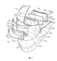
FIG. 1 is a front exploded and partially cut-away perspective view of an embodiment of a face protector with an embodiment of a lens assembly shown therein. -
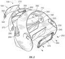
FIG. 2 is a rear exploded perspective view of the face protector and the lens assembly shown inFIG. 1 . -
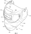
FIG. 3 is a front perspective view of the face protector and the lens assembly shown inFIGS. 1 and2 . -
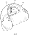
FIG. 4 is a rear perspective view of the face protector and the lens assembly shown inFIGS. 1 to 3 . -
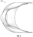
FIG. 5 is a bottom plan view of the face protector and the lens assembly shown inFIGS. 1 to 4 . -
FIG. 6 is a top plan view of the face protector and the lens assembly shown inFIGS. 1 to 5 . -
FIG. 7 is a rear elevational view of the face protector and the lens assembly shown inFIGS. 1 to 6 . -
FIG. 8 is a right side elevational view of the face protector and the lens assembly shown inFIGS. 1 to 7 , the left side elevational view being a mirror image thereof. -
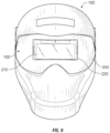
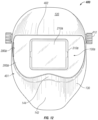
FIG. 9 is a front elevational view of the face protector and the lens assembly shown inFIGS. 1 to 8 , the left side elevational view being a mirror image thereof. -
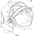
FIG. 10 is a rear perspective view of another embodiment of a face protector incorporating another embodiment of a lens assembly. -
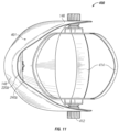
FIG. 11 is a bottom plan view of the face protector ofFIG. 10 . -
FIG. 12 is a front elevation view of the face protector ofFIGS. 10 and11 . -
FIG. 13 is a top plan view of the face protector ofFIGS. 10 to 12 . -
FIG. 14 is a rear elevation view of the face protector ofFIGS. 10 to 13 . -
FIG. 15 is a right side elevation view of the face protector ofFIGS. 10 to 14 . - Certain examples as disclosed herein provide for a face protector having a face plate with a front opening which extends across the eye region of a wearer and rearwardly around the sides of the face towards the ears, and a lens-in-a-lens assembly secured in the front opening.
- After reading this description it will become apparent to one skilled in the art how to implement the invention in various alternative embodiments and alternative applications. However, although various embodiments of the present invention will be described herein, it is understood that these embodiments are presented by way of example only, and not limitation. As such, this detailed description of various alternative embodiments should not be construed to limit the scope of the present invention.
- With reference to
FIGS. 1-9 , a first embodiment of a lens-in-a-lens assembly ("lens assembly") 100 of aface protector 105 will be described. In an exemplary embodiment, theface protector 105 is used in a welding application; however, in an alternative embodiments, theface protector 105 and/orface plate 110 is used in other applications such as, but not limited to, safety applications, commercial applications, do-it-yourself (DIY) applications, grinding, splash guard, sand blasting, food preparation, fork lift operations, tile cutting, wood cutting, wood chopping, face protection from flying particles, forced high pressure washing applications, during boat travel in sport leisure and commercial fishing, snowboarding, skiing, snowmobiling, hiking, hunting, paint ball, law enforcement, fire fighting, motorcycling, dune buggy or rails, ATV, air soft, spectator sports (e.g., NASCAR car racing, NFL/college football, NHL/college hockey), commercial activities such as airline industry, landscaping, and governmental activities such as military, lake patrols, etc. - With reference to
FIG. 3 , before describing thelens assembly 100, theface protector 105 will be generally described. Theface protector 105 protects the front of a user's head (i.e., forehead, face, eyes, cheeks, jaw, chin, mouth, nose, ears) from flash burn, ultraviolet light, sparks, heat, and/or other elements associated with the activity/application. - The
face protector 105 includes aface plate 110 preferably made of an injection molded thin, plastic material. Theface plate 110 has a configuration generally similar to the configuration of a human face and includes aforehead portion 120, acheek portion 130, ajaw portion 140, amouth portion 142, anose portion 144,ear portions 146, achin portion 148, and the replaceable/interchangeable lens assembly 100 that cover and protect the forehead, cheeks, jaw, mouth, nose, ears, chin, and eyes, respectively, of a user. - The
forehead portion 120 is just wider than the width of the head of the user, is curved rearwardly, and extends from the brow area to just above the forehead area of the user. Substantially all of the skull is not covered by theforehead portion 120 or the rest of theface protector 110. Although not shown, in alternative embodiments, theforehead portion 120 may include one or more ventilation sections for ventilating theface protector 110. On a front side 160 of theforehead portion 120, theforehead portion 120 may include an insert and/orindicia 182 displaying a trademark, logo, or other insignia pertinent to the application of theface protector 110. The mold used to make theface protector 110 may include different mold inserts for the different indicia so that the same mold, but different mold inserts, may be used to manufacture theface protectors 110 for different applications. - The
cheek portion 130 is curved rearwardly from thenose portion 144 and themouth portion 142 of theface plate 110, and protects the cheeks of a user. - The
jaw portion 140 is curved rearwardly from themouth portion 142 and thecheek portion 130 of theface plate 110, and protects the jaw area of a user. Thejaw portion 140 includes thechin portion 148, which has a cupped configuration for receiving the chin of a user. Thejaw portion 140 decreasingly tapers in width from the top of thejaw portion 140, just below thelens assembly 100, to the bottom of thechin portion 148. - The
mouth portion 142 is disposed between thenose portion 144 and thejaw portion 140, and protects the mouth of a user. Although not shown, in an alternative embodiment, themouth portion 142 may include ventilation holes in the grooves shown or in other areas of themouth portion 142 and/ornose portion 144. The mold used to make theface protector 110 may include different inserts for the different mouth and/or nose designs so that the same mold, but different inserts, may be used to manufacture the face protectors for different applications (e.g. face protectors with and without mouth/nose ventilation holes). - The front side of the
nose portion 144 may bow outward and therear side 162 of thenose portion 144 may be concave to accommodate the nose of the user. Although not shown, as discussed above, thenose portion 144 may include one or more ventilation holes in alternative embodiments. - The
ear portions 146 extend rearwardly from the opposite ends of thelens assembly 100, and decreasingly taper in dimension progressing rearwardly, and protect the entire ears of the user. Substantially rectangular-shapedholes 170 are disposed in upper portions of theear portions 146. Connectors may connect to theholes 170 from a back/inner side of theear portions 146 for connecting a strap (not shown) to theface protector 110 to retain theface protector 110 in position on the user's head. The strap may be elastic and/or adjustable for adjusting the length of the strap to accommodate different-sized heads. - The
face protector 110 may come in a one-size-fits-all configuration or may come in different sizes for different-sized heads (e.g., XL, L, M, S, child size). - An inner/back side of the
face plate 110 may include cushion member(s) to provide added comfort to the user when wearing theface protector 105. The cushion member(s) may be affixed/connected to an inner/back side of theface plate 110 using an adhesive and/or fasteners. The cushion member(s) may be made of a waterproof, breathable material. The cushion member(s) may include holes therein to increase the breathability and comfort of the cushion member(s) when against the skin of the user. The cushion member(s), like theface plate 110, may come in different sizes to allow the user to custom fit theface protector 105 for the user's specific facial dimensions. - Because of the face-forming, low profile of the
face plate 110, especially in thejaw portion 140, theface plate 110 allows the user to move one's head from side to side more easily because the lower jaw area of a normal welding helmet or mask hits the users shoulders and causes the helmet/mask to push up and/or off the user's face/head. Also, because of the rounded profile of theface plate 110, air flows better than other welding helmets because there is no 90-degree angle that the air has to move past. For example, theforehead portion 120 of theface plate 110 has a rounded profile compared to the 90-degree angles of other welding helmets. Also, because of the roundedspherical lens assembly 100, which will be described in more detail below, splatter, flying objects, and the like ricochet off thelens assembly 100 andface plate 110 with less impact and stress on theface plate 110, and thelens assembly 100 does not scratch so easily. - With reference generally to
FIGS. 1-9 , thelens assembly 100 will now be described in more detail. Thelens assembly 100 protects the user's eyes from flash burn (e.g., causing arc eyes, retina bums), ultraviolet light, sparks, heat, and/or other elements associated with the activity/application. Thelens assembly 100 also maximizes the user's general vision and peripheral vision, which helps the user to spot fires in the welding area (e.g., to the sides of the user) caused by hot metal sparks generated by the arc that ignite flammable objects. - The
lens assembly 100 is replaceable/interchangeable with other lenses (e.g., for different welding applications, for different applications) and fits within an eye opening 190 (FIG. 1 ) of theface plate 110. Thelens assembly 100 includes an Automatic Darkening Filter ("ADF")retainer lens 200, afront cover 210, anADF lens 220, apolycarbonate lens protector 230, aback cover 240, flat head screws 250, and threadedinserts 260. - The
ADF retainer lens 200 is partially spherical, toroidal, and/or cylindrical, providing the user with 180 degree viewing and unobstructed peripheral vision. Opposite peripheral/temple portions 270 of theADF retainer lens 200 include crescent-shapedholes 280 that overlap crescent-shapedholes 290 in recessedeye opening section 300. Fasteners may extend through theholes ADF retainer lens 200 to the recessedeye opening section 300 of theface plate 110. TheADF retainer lens 200 includes a central section with arectangular opening 310 having front upper and lower recessedsections 320, side cut-outs 330, and rearwardly extending receivingsection 335. The rearwardly extending receivingsection 335 includes rearwardly extending upper horizontal member, lower horizontal member, and side vertical members that together form an air/space pocket between theADF lens 220 and thefront cover 210 when thelens assembly 100 is assembled. In one embodiment, theADF retainer lens 200 is a # 10 shaded lens and is made of polycarbonate. In alternative embodiments, theADF retainer lens 200 is a shaded lens in the range of #2- #12 shaded lens. - The
front cover 210 protects theADF lens 220 from impact. Thefront cover 210 is transparent, un-shaded, rectangular/spherical/torical/cylindrical, made of polycarbonate and has a slight curved configuration/shape. Althoughfront cover 210 is a separate component secured in an opening in the retainer lens in the illustrated embodiment, it may alternatively comprise a transparent or substantially transparent cover portion formed integrally with the retainer lens. Thefront cover 210, when disposed in theADF retainer lens 200, is flush with the outer surface oflens 200. Rearward extendinglatch projections 340 extend fromopposite sides 350 of thefront cover 210 and extend through the side cut-outs 330 of the ADF retainer lens 200 (seeFIGS. 1 and2 ). - As indicated above, the
lens assembly 100 has a lens-in-a-lens design with theADF retainer lens 200 forming an outer holder lens and theADF lens 220 forming an inner lens carried within/by theADF retainer lens 200. The threaded inserts 260 are injected/added into a rear/back side of theADF retainer lens 200. - The
ADF lens 220 is substantially rectangular and has a rectangular frame portion and a rectangular lens portion held in the rectangular frame portion. In the embodiment shown, theADF lens 220 is a 5.08 cm X 10.80 cm (2 in. X 4.25 in.). ADF lens and is a shade #3 normally and darkens to shade #10 automatically when exposed to the flare of a welding arc. TheADF lens 220 is interchangeable with other 108 mm X 50.8 mm X 5 mm ADF filters and shades. In further embodiments, the outerADF retainer lens 200 is a shade which matches the shade of theADF lens 220, but these lenses may be of different shades in other embodiments. In an alternative embodiment, theADF lens 220 is a 10.16 cm X 10.16 cm (4 in. X 4 in.), or 10.16 cm X 12.70 cm. (4 in. X 5 in.). ADF lens, as described below in connection with the embodiment ofFIGS. 10 to 15 . In further embodiments, theADF lens 220 and/or the outerADF retainer lens 200 may be made of different shades and/or different types of ADF lenses. - A rectangular
polycarbonate lens protector 230 is disposed behind theADF lens 220. - The
rectangular back cover 240 includes a centralrectangular opening 360 and forwardly extending upper/lower flange members 370. A front of theback cover 240 includes a rectangular recessedsection 380 with side cut-outs 390. The recessedsection 380 in the front of theback cover 240 receives/retains thepolycarbonate lens protector 230 and theADF lens 220. The rearwardly extendinglatch projections 340 of thefront cover 210 latch into the side cut-outs 390 of theback cover 240. The flat head screws 250 are inserted through holes in the corners of theback cover 240 and threadably engage the threadedinserts 260 in the rear side of theADF retainer lens 200 to connect/assemble therectangular back cover 240, thepolycarbonate lens protector 230, and theADF lens 220, theADF retainer lens 200, and thefront cover 210 of thelens assembly 100 together. - Thus, the
lens assembly 100 protects the user's eyes from flash burn, ultraviolet light, sparks, heat, and/or other elements associated with the activity/application, and maximizes the user's peripheral/overall vision. Increased peripheral vision helps the user to spot fires or other objects in the welding area (e.g., to the sides of the user) caused by hot metal sparks generated by the arc that ignite flammable objects. -
FIGS. 10 to 15 illustrate a second embodiment of aface protector 400 comprising aface plate 401 having afront opening 402. A lens-in-a-lens assembly 100A which is similar to that of the previous embodiment but of different dimensions is mounted infront opening 402 in the same manner as described in the previous embodiment forlens assembly 100. Parts of assembly 100A which are equivalent to corresponding parts in the previous embodiment but of different dimensions or shape are provided with the same reference numbers as in the previous embodiment, followed by the letter A, and reference is made to the above description of these parts in the first embodiment for details of their materials and functions. The lens-in-a-lens assembly 100A and thefront opening 402 for receiving the assembly are both larger in this embodiment than the previous embodiment, offering an increased viewing area to the wearer. - The
face plate 401 is similar in shape and made of the same material asface plate 110 of the previous embodiment, and like reference numbers are used for like parts as appropriate. Reference is made to the description of these parts in connection with the previous embodiment, and the parts are not described in detail in connection with this embodiment, apart from any variations from the previous embodiment. Astrap assembly 410 withconnectors 412 which connect to theholes 170 in the back side ofear portions 146 of the face plate is illustrated inFIGS. 10 to 15 , and a similar strap assembly may be used to connect to theholes 170 in the first embodiment.Strap assembly 410 is used to retainface protector 400 in position on the user's head. Thestraps 414 ofassembly 410 may be elastic or adjustable to accommodate a range of different size heads, as described above. - As can be seen by comparing
FIGS. 9 and12 , the recessed front or eye opening 402 in theface plate 401 of this embodiment is larger than the recessed eye opening 300 of the first embodiment, and the ADF retainer lens 200A of the lens assembly is of shape and dimensions substantially matching those of opening 402 so that it is a close fit in the opening when opposite peripheral/temple portions 270A are secured to the opposite ear portions or side portions of the face plate. As in the previous embodiment, retainer lens 200A has crescent shaped holes 280A that overlap corresponding holes in the recessed eye opening section, andfasteners 281 extend through the overlapping holes to secure the retainer lens in the recessed opening. The retainer lens 200A is of increased height relative to theretainer lens 200 in the previous embodiment, so that it can accommodate a larger ADF lens 220A. As can be seen by comparing the rear end views of theface protectors FIGS. 7 and14 , respectively, the ADF lens 220A is of larger height thanlens 220 but of substantially the same width, and may be of substantially square shape. The larger size of lenses 200A and 220A provides increased visibility to the user. The other parts of the lens assembly 100A which protect lens 220A and releasably secure the lens to retainer lens 200A are identical to those of the previous embodiment, apart from the increased dimensions of front cover 210 A, lens protector 230A, and the frame or back cover 240A which holds lens 200A, as well as the front opening 310A inretainer lens 200, to accommodate the increased size of lens 220A. Apart from the change in dimensions, these parts are identical to the corresponding parts in the first embodiment and are therefore not described in any more detail. - The dimensions of the ADF lens 220A may be approximately 10.16 cm X 10.16 cm (4.0 in. X 4.0 in.) or 10.16 cm X 12.70 cm. (4.0 in. X 5.0 in.), with the height dimensions of retainer lens 200A, the front opening 310A in the retainer lens, and the recessed
opening 402 in the face plate in which lens 200A is mounted similarly scaled up to accommodate the increased size of lens 220A. As in the previous embodiment, lenses 200A and 220A may be of any selected initial lens shade and darkened lens shades, and lens 200A and 220A may be replaced or interchanged with other lenses of equivalent shapes and dimensions but different lens properties, as desired. - As in the previous embodiment, the lens-in-lens assembly 100A protects a wearer's eyes while allowing peripheral vision, and one or both lenses are replaceable or interchangeable as described above in connection with the first embodiment.
- The above figures may depict exemplary configurations for the invention, which is done to aid in understanding the features and functionality that can be included in the invention. The invention is not restricted to the illustrated architectures or configurations, but can be implemented using a variety of alternative architectures and configurations. Additionally, although the invention is described above in terms of various exemplary embodiments and implementations, it should be understood that the various features and functionality described in one or more of the individual embodiments with which they are described, but instead can be applied, alone or in some combination, to one or more of the other embodiments of the invention, whether or not such embodiments are described and whether or not such features are presented as being a part of a described embodiment. Thus the scope of the present invention in any following claims should not be limited by any of the above-described exemplary embodiments.
Claims (14)
- A lens assembly (100) for a welding mask the lens assembly configured to be secured in a front opening (190) in a face plate (110) of the welding mask, the lens assembly (100) comprising:a first lens (200) configured to be secured in the front opening (190) of the face plate and being curved, the first lens (200) having a central portion extending across the face of a wearer and side portions (270) configured to provide peripheral vision to the wearer; anda second lens (220) of smaller dimensions secured behind the first lens (200) to provide a lens- in-a-lens configuration the second lens being adapted to extend in front of the wearer's eyes when looking forwards;wherein the first lens is adapted to extend over at least part of the sides of the wearer's face on each side of the wearer's eyes to provide said peripheral vision to the wearer,wherein the first lens and the second lens are both automatic darkening filter (ADF) lenses, andthe first lens has a transparent cover portion (210) in a central opening (310) of the first lens in front of the second lens to protect the second lens from impact.
- The lens assembly of claim 1, wherein at least one lens of the lens assembly is removably mounted to allow lens replacement.
- The lens assembly of claim 1 or 2, wherein the second lens is releasably secured behind the first lens, whereby the second lens is replaceable.
- The lens assembly of any preceding claim wherein the central opening (310) in the first lens comprises rearwardly extending receiving section (335) configured to form an air/space pocket between the second lens (220) and the transparent cover portion (210).
- The lens assembly of any preceding claim, further comprising a rear retainer frame (240) holding the second lens and releasably secured to the first lens.
- The lens assembly of claim 4 or 5, further comprising an at least substantially transparent lens protector of shape and dimensions substantially matching the shape and dimensions of the second lens, the lens protector being secured between the rear retainer frame and second lens.
- The lens assembly of claim 1, wherein at least one of said first and second lens (200, 220) are releasably secured in said lens assembly and adapted to be interchangeable with interchangeable lenses having different lens properties.
- The lens assembly of any preceding claim, wherein the second lens is a substantially flat lens.
- The lens assembly of any preceding claim, wherein the transparent cover portion comprises a separate front cover member secured in the central opening.
- The lens assembly of claim 9 wherein the transparent cover portion is curved.
- The lens assembly of claim 10, wherein the first lens and front cover member are of substantially matching curvature.
- A face protector, comprising the lens assembly of any preceding claim anda face plate (110, 401) having portions configured to protect the forehead, cheeks, jaw, chin, mouth, ears, and nose of a wearer, the face plate having a front opening (190, 402) configured for positioning over the eyes of a wearer and extending rearwardly over opposite sides of the face towards the ears of a wearer; wherein the lens assembly is secured in the front opening of the face plate,the first lens being secured in the front opening and substantially flush with at least the forehead portion (120) of the face plate, the first lens (200, 200A) being of shape and dimensions which substantially match the shape and dimensions of the front opening.
- A combination comprising:(i) the lens assembly of claim 7 or the face protector of claim 12 as dependent upon claim 7; and(ii) at least one set of said interchangeable lenses.
- The combination of claim 13 wherein said set of interchangeable lenses comprise automatic darkening filter (ADF) lenses of different shades.
Applications Claiming Priority (2)
| Application Number | Priority Date | Filing Date | Title |
|---|---|---|---|
| US26376509P | 2009-11-23 | 2009-11-23 | |
| PCT/US2010/057508 WO2011063287A2 (en) | 2009-11-23 | 2010-11-19 | Face protector lens assembly and method of use |
Publications (4)
| Publication Number | Publication Date |
|---|---|
| EP2503971A2 EP2503971A2 (en) | 2012-10-03 |
| EP2503971A4 EP2503971A4 (en) | 2017-11-15 |
| EP2503971C0 EP2503971C0 (en) | 2025-01-08 |
| EP2503971B1 true EP2503971B1 (en) | 2025-01-08 |
Family
ID=44060377
Family Applications (1)
| Application Number | Title | Priority Date | Filing Date |
|---|---|---|---|
| EP10832297.5A Active EP2503971B1 (en) | 2009-11-23 | 2010-11-19 | Face protector lens assembly |
Country Status (4)
| Country | Link |
|---|---|
| US (1) | US8438662B2 (en) |
| EP (1) | EP2503971B1 (en) |
| CA (1) | CA2780910A1 (en) |
| WO (1) | WO2011063287A2 (en) |
Families Citing this family (35)
| Publication number | Priority date | Publication date | Assignee | Title |
|---|---|---|---|---|
| US20170031525A1 (en) | 2010-05-14 | 2017-02-02 | Racing Optics, Inc. | Touch screen shield |
| US20110285957A1 (en) * | 2010-05-24 | 2011-11-24 | William Mikulenka | Limited access and antifog protective eyewear for welding |
| US8264265B2 (en) * | 2010-09-30 | 2012-09-11 | Kimberly-Clark Worldwide, Inc. | Automatic darkening filter (ADF) eye protection device with improved drive circuitry |
| USD683906S1 (en) * | 2010-10-26 | 2013-06-04 | Kimberly-Clark Worldwide, Inc. | Welding auto-darkening filter |
| USD683502S1 (en) * | 2010-10-26 | 2013-05-28 | Kimberly-Clark Worldwide, Inc. | Welding auto-darkening filter |
| USD678619S1 (en) * | 2010-10-26 | 2013-03-19 | Kimberly-Clark Worldwide, Inc. | Welding auto-darkening filter assembly |
| KR101201483B1 (en) * | 2011-05-17 | 2012-11-14 | 김동근 | Welding mask |
| KR101825747B1 (en) * | 2011-06-07 | 2018-02-05 | 엘지이노텍 주식회사 | Camera module and method for assembling the same |
| US8826464B2 (en) * | 2011-09-29 | 2014-09-09 | Tecmen Electronics Co., Ltd. | Filter holding system for welding mask |
| FR2997824A1 (en) * | 2012-11-13 | 2014-05-16 | Stand 21 | REINFORCED VISOR FOR COMPETITION PILOT HELMETS |
| USD699397S1 (en) | 2013-06-20 | 2014-02-11 | J. Dan Moore | Helmet with weather shield |
| EP2839817B1 (en) | 2013-08-05 | 2019-07-31 | Optrel Holding AG | Face protector |
| US9295297B2 (en) | 2014-06-17 | 2016-03-29 | Racing Optics, Inc. | Adhesive mountable stack of removable layers |
| US10845519B2 (en) | 2016-04-27 | 2020-11-24 | Rayotek Scientific, Inc. | Lens for protective gear |
| EP3241533A1 (en) * | 2016-05-04 | 2017-11-08 | 3M Innovative Properties Company | A curved eye protection shield for welding protection |
| CN109152661B (en) | 2016-05-12 | 2020-02-04 | 3M创新有限公司 | Protective helmet comprising a curved switchable shutter and comprising a plurality of antireflection layers |
| CN106038058A (en) * | 2016-07-01 | 2016-10-26 | 宁波吉欧光电科技有限公司 | Digital automatic light-changing welding eye patches |
| US20180280197A1 (en) * | 2017-03-30 | 2018-10-04 | Illinois Tool Works Inc. | Head worn devices having a variable shade component and fixed shade component, and methods of operation |
| USD918483S1 (en) * | 2018-10-26 | 2021-05-04 | 3M Innovative Properties Co. | User interface for a welding helmet |
| WO2020160492A1 (en) | 2019-02-01 | 2020-08-06 | Racing Optics, Inc. | Thermoform windshield stack with integrated formable mold |
| US11846788B2 (en) | 2019-02-01 | 2023-12-19 | Racing Optics, Inc. | Thermoform windshield stack with integrated formable mold |
| US11364715B2 (en) | 2019-05-21 | 2022-06-21 | Racing Optics, Inc. | Polymer safety glazing for vehicles |
| US11912001B2 (en) | 2019-12-03 | 2024-02-27 | Ro Technologies, Llc | Method and apparatus for reducing non-normal incidence distortion in glazing films |
| US11648723B2 (en) | 2019-12-03 | 2023-05-16 | Racing Optics, Inc. | Method and apparatus for reducing non-normal incidence distortion in glazing films |
| USD933307S1 (en) * | 2020-02-14 | 2021-10-12 | Med-Eng, Llc | Helmet |
| US11548356B2 (en) | 2020-03-10 | 2023-01-10 | Racing Optics, Inc. | Protective barrier for safety glazing |
| US20210285661A1 (en) | 2020-03-10 | 2021-09-16 | Wolf Steel Ltd. | Heating and cooling appliance |
| US11681144B1 (en) * | 2021-02-15 | 2023-06-20 | D'Angelo Technologies, LLC | Method, system, and apparatus for mixed reality |
| US11490667B1 (en) | 2021-06-08 | 2022-11-08 | Racing Optics, Inc. | Low haze UV blocking removable lens stack |
| US11709296B2 (en) | 2021-07-27 | 2023-07-25 | Racing Optics, Inc. | Low reflectance removable lens stack |
| US12140781B2 (en) | 2021-07-27 | 2024-11-12 | Laminated Film Llc | Low reflectance removable lens stack |
| US11307329B1 (en) | 2021-07-27 | 2022-04-19 | Racing Optics, Inc. | Low reflectance removable lens stack |
| US12162330B2 (en) | 2022-02-08 | 2024-12-10 | Ro Technologies, Llc | Multi-layer windshield film having progressive thickness layers |
| US11933943B2 (en) | 2022-06-06 | 2024-03-19 | Laminated Film Llc | Stack of sterile peelable lenses with low creep |
| US11808952B1 (en) | 2022-09-26 | 2023-11-07 | Racing Optics, Inc. | Low static optical removable lens stack |
Family Cites Families (34)
| Publication number | Priority date | Publication date | Assignee | Title |
|---|---|---|---|---|
| US2180216A (en) * | 1938-02-15 | 1939-11-14 | Leslie E Snodgrass | Mask |
| US2978709A (en) * | 1957-03-11 | 1961-04-11 | Floyd L Atha | Face shield |
| US3112490A (en) * | 1960-09-19 | 1963-12-03 | Jr Robert Malcom | Filter plate assembly for welding helmets and the like |
| US3415595A (en) * | 1965-01-21 | 1968-12-10 | Harry W. Nelson | Prescription lenses for welder's helmet and the like |
| US3756692A (en) * | 1971-07-15 | 1973-09-04 | Univ Johns Hopkins | Photochromic protective eye shield lens |
| US3868727A (en) * | 1973-09-24 | 1975-03-04 | James W Paschall | Welding hood |
| USD264891S (en) * | 1979-05-18 | 1982-06-15 | Tegma Ab | Welding shield |
| SE445969B (en) * | 1983-03-24 | 1986-08-04 | Holmstroem Per Olof | WELD PROTECTION WHICH IS PROVIDED TO BE APPLIED IN FRONT OF THE WELDEN'S FACE TO PROTECT AGAINST HARMFUL RADIATION |
| US4774723A (en) * | 1987-03-02 | 1988-10-04 | The Fibre Metal Products Company | Welding mask lens spring and flash barrier |
| SE467087B (en) * | 1989-06-05 | 1992-05-25 | Hoernell Elektrooptik Ab | Welding helmet comes with one kind of quick filter |
| US5673431A (en) * | 1995-08-25 | 1997-10-07 | Dwight A. Marshall | Face mask safety shield |
| US6006366A (en) * | 1997-10-10 | 1999-12-28 | Vondrak; Paul C. | Polarized lens for helmet face shield |
| US6035451A (en) * | 1998-03-10 | 2000-03-14 | Minnesota Mining And Manufacturing Company | Protective helmet system with cam for attaching first and second face shields thereto |
| US6151711A (en) * | 1999-04-01 | 2000-11-28 | Jackson Products, Inc. | Welding helmet with removable face plate and lens cartridge |
| US20060010572A1 (en) | 2003-02-03 | 2006-01-19 | Douglas Thomas D A | Helmet face shield |
| WO2005089487A2 (en) * | 2004-03-18 | 2005-09-29 | Save Phace, Inc. | Face protector and method of use |
| US20070192946A1 (en) * | 2004-03-18 | 2007-08-23 | Wright Jerry D | Face protector and method of use |
| USD522179S1 (en) * | 2004-09-30 | 2006-05-30 | Save Phace, Inc. | Face protector |
| USD518242S1 (en) * | 2005-04-20 | 2006-03-28 | Save Phace, Inc. | Face protector |
| US20060272067A1 (en) * | 2005-06-06 | 2006-12-07 | Mario Gagnon | Modular mask system |
| USD526094S1 (en) * | 2005-07-07 | 2006-08-01 | Chun-Nan Chen | Mask |
| USD539988S1 (en) * | 2005-08-09 | 2007-04-03 | 3M Innovative Properties Company | Welding helmet visor |
| USD526097S1 (en) * | 2005-08-09 | 2006-08-01 | 3M Innovative Properties Company | Side portion of a welding helmet |
| KR100767702B1 (en) * | 2006-03-24 | 2007-10-18 | 오토스테크 주식회사 | Multifunction security cotton |
| US8990963B2 (en) * | 2006-08-23 | 2015-03-31 | Lincoln Global, Inc. | User-friendly welding helmet assembly |
| USD569557S1 (en) * | 2006-09-05 | 2008-05-20 | Hjc Co., Ltd. | Shield for helmet |
| USD557460S1 (en) * | 2006-10-26 | 2007-12-11 | Sport Maska Inc. | Helmet for hockey goalie or the like |
| USD555290S1 (en) * | 2007-01-30 | 2007-11-13 | Jerry Dean Wright | Face protector |
| USD558403S1 (en) * | 2007-02-12 | 2007-12-25 | Chi Keung Lee | Mask |
| USD584009S1 (en) * | 2008-01-31 | 2008-12-30 | 3M Innovative Properties Company | Welding helmet frame |
| US8381312B2 (en) * | 2008-02-04 | 2013-02-26 | Won Su Seo | Welding mask |
| USD586051S1 (en) * | 2008-05-15 | 2009-02-03 | Optical Engineering Company, Inc. | Protective helmet |
| WO2010088596A1 (en) * | 2009-01-30 | 2010-08-05 | Alphamicron, Inc. | Attachable optical element arrangements and methods |
| USD624705S1 (en) * | 2009-08-13 | 2010-09-28 | Jerry Dean Wright | Face protector |
-
2010
- 2010-11-19 CA CA2780910A patent/CA2780910A1/en not_active Abandoned
- 2010-11-19 US US12/950,846 patent/US8438662B2/en not_active Expired - Fee Related
- 2010-11-19 EP EP10832297.5A patent/EP2503971B1/en active Active
- 2010-11-19 WO PCT/US2010/057508 patent/WO2011063287A2/en not_active Ceased
Also Published As
| Publication number | Publication date |
|---|---|
| EP2503971A4 (en) | 2017-11-15 |
| WO2011063287A3 (en) | 2011-10-06 |
| US8438662B2 (en) | 2013-05-14 |
| EP2503971C0 (en) | 2025-01-08 |
| US20110119801A1 (en) | 2011-05-26 |
| WO2011063287A2 (en) | 2011-05-26 |
| EP2503971A2 (en) | 2012-10-03 |
| CA2780910A1 (en) | 2011-05-26 |
Similar Documents
| Publication | Publication Date | Title |
|---|---|---|
| US8438662B2 (en) | Face protector lens assembly and method of use | |
| US8726412B2 (en) | Face protector lens assembly and method of use | |
| US9271871B2 (en) | Face protector lens assembly and method of use | |
| US10736782B2 (en) | Face protector | |
| US20120222201A1 (en) | Goggles with removable frame and methods of making and using the same | |
| US11376161B2 (en) | Welder protector | |
| US6178552B1 (en) | Welding helmet | |
| US5956760A (en) | Facial sunshield with hinged visor/cap | |
| US20110314580A1 (en) | Headgear with means for retaining eyewear | |
| CN111132573B (en) | Welding helmet | |
| US20150033430A1 (en) | Face protector for welder | |
| US20090229043A1 (en) | Head protective gear | |
| US20200397615A1 (en) | Welding Hood | |
| CA3058396A1 (en) | Head worn devices having a variable shade component and fixed shade component, and methods of operation | |
| WO2015034575A1 (en) | Face protector lens assembly and method of use | |
| EP3354147B1 (en) | Protective gear and method of producing protective gear | |
| US20090044318A1 (en) | Lens inserts for cage masks | |
| US20190175410A1 (en) | Adjustable Goggle-Integrated Face Shield | |
| US20070050892A1 (en) | Welder's helmet with respirator | |
| CN212808802U (en) | Goggles in AR helmet of adaptation | |
| CN210903650U (en) | Goggles type automatic light-changing welding mask | |
| US20240407952A1 (en) | Cold weather welding mask | |
| CN211244053U (en) | Laser protective mask | |
| JP2022002593A (en) | Transparent face shield and head fitting body | |
| CA2571435A1 (en) | Protective nose guard |
Legal Events
| Date | Code | Title | Description |
|---|---|---|---|
| PUAI | Public reference made under article 153(3) epc to a published international application that has entered the european phase |
Free format text: ORIGINAL CODE: 0009012 |
|
| 17P | Request for examination filed |
Effective date: 20120608 |
|
| AK | Designated contracting states |
Kind code of ref document: A2 Designated state(s): AL AT BE BG CH CY CZ DE DK EE ES FI FR GB GR HR HU IE IS IT LI LT LU LV MC MK MT NL NO PL PT RO RS SE SI SK SM TR |
|
| DAX | Request for extension of the european patent (deleted) | ||
| A4 | Supplementary search report drawn up and despatched |
Effective date: 20171017 |
|
| RIC1 | Information provided on ipc code assigned before grant |
Ipc: A61F 9/06 20060101AFI20171011BHEP Ipc: F16P 1/06 20060101ALI20171011BHEP Ipc: B23K 9/32 20060101ALI20171011BHEP |
|
| STAA | Information on the status of an ep patent application or granted ep patent |
Free format text: STATUS: EXAMINATION IS IN PROGRESS |
|
| 17Q | First examination report despatched |
Effective date: 20210825 |
|
| STAA | Information on the status of an ep patent application or granted ep patent |
Free format text: STATUS: THE APPLICATION IS DEEMED TO BE WITHDRAWN |
|
| 18D | Application deemed to be withdrawn |
Effective date: 20220105 |
|
| STAA | Information on the status of an ep patent application or granted ep patent |
Free format text: STATUS: EXAMINATION IS IN PROGRESS |
|
| 19U | Interruption of proceedings before grant |
Effective date: 20190821 |
|
| D18D | Application deemed to be withdrawn (deleted) | ||
| 19W | Proceedings resumed before grant after interruption of proceedings |
Effective date: 20230502 |
|
| 17Q | First examination report despatched |
Effective date: 20230511 |
|
| RAP3 | Party data changed (applicant data changed or rights of an application transferred) |
Owner name: MENTA, GREGORY S. |
|
| RIN1 | Information on inventor provided before grant (corrected) |
Inventor name: MENTA, GREGORY S. |
|
| GRAP | Despatch of communication of intention to grant a patent |
Free format text: ORIGINAL CODE: EPIDOSNIGR1 |
|
| STAA | Information on the status of an ep patent application or granted ep patent |
Free format text: STATUS: GRANT OF PATENT IS INTENDED |
|
| INTG | Intention to grant announced |
Effective date: 20240708 |
|
| GRAS | Grant fee paid |
Free format text: ORIGINAL CODE: EPIDOSNIGR3 |
|
| GRAA | (expected) grant |
Free format text: ORIGINAL CODE: 0009210 |
|
| STAA | Information on the status of an ep patent application or granted ep patent |
Free format text: STATUS: THE PATENT HAS BEEN GRANTED |
|
| AK | Designated contracting states |
Kind code of ref document: B1 Designated state(s): AL AT BE BG CH CY CZ DE DK EE ES FI FR GB GR HR HU IE IS IT LI LT LU LV MC MK MT NL NO PL PT RO RS SE SI SK SM TR |
|
| REG | Reference to a national code |
Ref country code: CH Ref legal event code: EP |
|
| REG | Reference to a national code |
Ref country code: DE Ref legal event code: R096 Ref document number: 602010069637 Country of ref document: DE |
|
| REG | Reference to a national code |
Ref country code: IE Ref legal event code: FG4D |
|
| U01 | Request for unitary effect filed |
Effective date: 20250206 |
|
| REG | Reference to a national code |
Ref country code: CH Ref legal event code: PK Free format text: BERICHTIGUNGEN |
|
| U07 | Unitary effect registered |
Designated state(s): AT BE BG DE DK EE FI FR IT LT LU LV MT NL PT RO SE SI Effective date: 20250227 |
|
| RAP2 | Party data changed (patent owner data changed or rights of a patent transferred) |
Owner name: MENTA PATENT PARTNERS, LLC |
|
| REG | Reference to a national code |
Ref country code: GB Ref legal event code: 732E Free format text: REGISTERED BETWEEN 20250327 AND 20250402 |
|
| RIN2 | Information on inventor provided after grant (corrected) |
Inventor name: MENTA, GREGORY S. |
|
| U1K | Transfer of rights of the unitary patent after the registration of the unitary effect |
Owner name: MENTA PATENT PARTNERS, LLC; US |
|
| PG25 | Lapsed in a contracting state [announced via postgrant information from national office to epo] |
Ref country code: RS Free format text: LAPSE BECAUSE OF FAILURE TO SUBMIT A TRANSLATION OF THE DESCRIPTION OR TO PAY THE FEE WITHIN THE PRESCRIBED TIME-LIMIT Effective date: 20250408 |
|
| PG25 | Lapsed in a contracting state [announced via postgrant information from national office to epo] |
Ref country code: PL Free format text: LAPSE BECAUSE OF FAILURE TO SUBMIT A TRANSLATION OF THE DESCRIPTION OR TO PAY THE FEE WITHIN THE PRESCRIBED TIME-LIMIT Effective date: 20250108 |
|
| PG25 | Lapsed in a contracting state [announced via postgrant information from national office to epo] |
Ref country code: ES Free format text: LAPSE BECAUSE OF FAILURE TO SUBMIT A TRANSLATION OF THE DESCRIPTION OR TO PAY THE FEE WITHIN THE PRESCRIBED TIME-LIMIT Effective date: 20250108 |
|
| PG25 | Lapsed in a contracting state [announced via postgrant information from national office to epo] |
Ref country code: NO Free format text: LAPSE BECAUSE OF FAILURE TO SUBMIT A TRANSLATION OF THE DESCRIPTION OR TO PAY THE FEE WITHIN THE PRESCRIBED TIME-LIMIT Effective date: 20250408 Ref country code: IS Free format text: LAPSE BECAUSE OF FAILURE TO SUBMIT A TRANSLATION OF THE DESCRIPTION OR TO PAY THE FEE WITHIN THE PRESCRIBED TIME-LIMIT Effective date: 20250508 |
|
| PG25 | Lapsed in a contracting state [announced via postgrant information from national office to epo] |
Ref country code: HR Free format text: LAPSE BECAUSE OF FAILURE TO SUBMIT A TRANSLATION OF THE DESCRIPTION OR TO PAY THE FEE WITHIN THE PRESCRIBED TIME-LIMIT Effective date: 20250108 |
|
| PG25 | Lapsed in a contracting state [announced via postgrant information from national office to epo] |
Ref country code: GR Free format text: LAPSE BECAUSE OF FAILURE TO SUBMIT A TRANSLATION OF THE DESCRIPTION OR TO PAY THE FEE WITHIN THE PRESCRIBED TIME-LIMIT Effective date: 20250409 |
|
| PG25 | Lapsed in a contracting state [announced via postgrant information from national office to epo] |
Ref country code: SM Free format text: LAPSE BECAUSE OF FAILURE TO SUBMIT A TRANSLATION OF THE DESCRIPTION OR TO PAY THE FEE WITHIN THE PRESCRIBED TIME-LIMIT Effective date: 20250108 |
|
| PG25 | Lapsed in a contracting state [announced via postgrant information from national office to epo] |
Ref country code: CZ Free format text: LAPSE BECAUSE OF FAILURE TO SUBMIT A TRANSLATION OF THE DESCRIPTION OR TO PAY THE FEE WITHIN THE PRESCRIBED TIME-LIMIT Effective date: 20250108 |
|
| PG25 | Lapsed in a contracting state [announced via postgrant information from national office to epo] |
Ref country code: SK Free format text: LAPSE BECAUSE OF FAILURE TO SUBMIT A TRANSLATION OF THE DESCRIPTION OR TO PAY THE FEE WITHIN THE PRESCRIBED TIME-LIMIT Effective date: 20250108 |
|
| PLBE | No opposition filed within time limit |
Free format text: ORIGINAL CODE: 0009261 |
|
| STAA | Information on the status of an ep patent application or granted ep patent |
Free format text: STATUS: NO OPPOSITION FILED WITHIN TIME LIMIT |
|
| REG | Reference to a national code |
Ref country code: CH Ref legal event code: L10 Free format text: ST27 STATUS EVENT CODE: U-0-0-L10-L00 (AS PROVIDED BY THE NATIONAL OFFICE) Effective date: 20251119 |
|
| 26N | No opposition filed |
Effective date: 20251009 |
|
| U20 | Renewal fee for the european patent with unitary effect paid |
Year of fee payment: 16 Effective date: 20251201 |
|
| REG | Reference to a national code |
Ref country code: CH Ref legal event code: H13 Free format text: ST27 STATUS EVENT CODE: U-0-0-H10-H13 (AS PROVIDED BY THE NATIONAL OFFICE) Effective date: 20260623 |
|
| PGFP | Annual fee paid to national office [announced via postgrant information from national office to epo] |
Ref country code: GB Payment date: 20251223 Year of fee payment: 16 |
|
| PG25 | Lapsed in a contracting state [announced via postgrant information from national office to epo] |
Ref country code: MC Free format text: LAPSE BECAUSE OF FAILURE TO SUBMIT A TRANSLATION OF THE DESCRIPTION OR TO PAY THE FEE WITHIN THE PRESCRIBED TIME-LIMIT Effective date: 20250108 |
|
| PG25 | Lapsed in a contracting state [announced via postgrant information from national office to epo] |
Ref country code: CH Free format text: LAPSE BECAUSE OF NON-PAYMENT OF DUE FEES Effective date: 20251130 |