EP2503936B1 - Magnetic field strength threshold alarm - Google Patents
Magnetic field strength threshold alarm Download PDFInfo
- Publication number
- EP2503936B1 EP2503936B1 EP10831960.9A EP10831960A EP2503936B1 EP 2503936 B1 EP2503936 B1 EP 2503936B1 EP 10831960 A EP10831960 A EP 10831960A EP 2503936 B1 EP2503936 B1 EP 2503936B1
- Authority
- EP
- European Patent Office
- Prior art keywords
- magnetic field
- field strength
- sensor
- pivotable member
- mri
- Prior art date
- Legal status (The legal status is an assumption and is not a legal conclusion. Google has not performed a legal analysis and makes no representation as to the accuracy of the status listed.)
- Active
Links
Images





Classifications
-
- G—PHYSICS
- G08—SIGNALLING
- G08B—SIGNALLING SYSTEMS, e.g. PERSONAL CALLING SYSTEMS; ORDER TELEGRAPHS; ALARM SYSTEMS
- G08B21/00—Alarms responsive to a single specified undesired or abnormal condition and not otherwise provided for
- G08B21/02—Alarms for ensuring the safety of persons
-
- B—PERFORMING OPERATIONS; TRANSPORTING
- B82—NANOTECHNOLOGY
- B82Y—SPECIFIC USES OR APPLICATIONS OF NANOSTRUCTURES; MEASUREMENT OR ANALYSIS OF NANOSTRUCTURES; MANUFACTURE OR TREATMENT OF NANOSTRUCTURES
- B82Y25/00—Nanomagnetism, e.g. magnetoimpedance, anisotropic magnetoresistance, giant magnetoresistance or tunneling magnetoresistance
-
- G—PHYSICS
- G01—MEASURING; TESTING
- G01R—MEASURING ELECTRIC VARIABLES; MEASURING MAGNETIC VARIABLES
- G01R33/00—Arrangements or instruments for measuring magnetic variables
- G01R33/02—Measuring direction or magnitude of magnetic fields or magnetic flux
- G01R33/038—Measuring direction or magnitude of magnetic fields or magnetic flux using permanent magnets, e.g. balances, torsion devices
- G01R33/0385—Measuring direction or magnitude of magnetic fields or magnetic flux using permanent magnets, e.g. balances, torsion devices in relation with magnetic force measurements
-
- G—PHYSICS
- G01—MEASURING; TESTING
- G01R—MEASURING ELECTRIC VARIABLES; MEASURING MAGNETIC VARIABLES
- G01R33/00—Arrangements or instruments for measuring magnetic variables
- G01R33/20—Arrangements or instruments for measuring magnetic variables involving magnetic resonance
- G01R33/28—Details of apparatus provided for in groups G01R33/44 - G01R33/64
- G01R33/288—Provisions within MR facilities for enhancing safety during MR, e.g. reduction of the specific absorption rate [SAR], detection of ferromagnetic objects in the scanner room
Definitions
- the present invention is in the field of devices for detecting magnetic field strength in the vicinity of an operating magnetic resonance imager (MRI) and responding when a preset magnetic field strength is exceeded.
- MRI magnetic resonance imager
- MRI Magnetic resonance Imaging
- the strong magnetic field associated with the area near to the MRI presents a danger of ferromagnetic objects being attracted to the strong magnetic field.
- a ferromagnetic detection system as described in Patent No. 7,489,128 MRI PROTECTOR is employed at the entrance of the room containing the MRI machine. This device will provide an alarm should a device containing ferromagnetic material pass through the ferromagnetic detector portal.
- ferromagnetic detectors do not prove useful in this situation other than to alert personnel that a potential risk may be present.
- Medical equipment such as infusion pumps, contrast injectors, patient monitors as well as anesthesia machines, is commonly necessary in the room containing the MRI machine.
- a contrast injector may inject an incorrect quantity of contrast agent when the device is exposed to a magnetic field greater than its design magnetic field maximum value.
- a variety of medical devices can operate safely in the vicinity of the MRI magnet if precautions are made to insure that the medical device is kept in an area where the magnetic field strength is below the limit where the device will perform correctly and / or will not present a ferromagnetic projectile risk.
- Medical equipment brought into the MRI room is quite commonly on carts with caster wheels. The equipment may, therefore, be easily moved or accidently bumped into an area where the magnetic field is dangerously high. Rarely are there markings indicating the various magnetic field strengths on the floor or elsewhere. As a result, the personnel may not be aware of the present danger. What is needed is a device to alert the personnel of the dangerous magnetic field in which the medical device is immersed.
- Electromagnetic interference can cause a degradation of the diagnostic quality of the image produced by the MRI process. As a consequence, electrical equipment is not brought into the screen room unless absolutely necessary and only then after a rigorous testing process to validate that the device does not degrade the performance of the MRI. Even after this validation process, there is still a significant risk that the MRI image quality may be compromised.
- Equipment such as patient monitors, infusion pumps and power injectors are moved frequently within the screen room. As such, a power cord supplying electricity to the equipment is inconvenient as well as being a potential risk of electromagnetic interference. Because of this, most electrical equipment brought into the MRI screen room is battery operated.
- Magnetic field strength alarms are known for detecting the magnetic field strength in the MRI environment.
- U.S. Pat. No. 4,954,812 entitled MAGNETIC FIELD ALARM INDICATOR discloses a magnetic field alarm detector comprised of a plurality of magnetic field detectors mounted in a horizontal plane for detecting respective rotational components of a magnetic field.
- At least 3 sensors must be used. More sensors are needed for better rotational sensitivity uniformity.
- the Hall Effect sensors used as well as the necessary processing electronics use a significant amount of electrical power.
- the invention disclosed consumes power anytime the device described is monitoring the magnetic field strength. As a consequence, the batteries must be charged or replaced regularly. Further, since the disclosed invention must be powered at all times while the device is in the screen room, there is a significant risk of the device causing electromagnetic interference. This risk is increased if a number of pieces of medical equipment in the screen room are fitted with the alarm described in the invention.
- U.S. Patent Application No. 2009/0251316 entitled “MAGNETIC PROXIMITY SENSOR SYSTEM AND ASSOCIATED METHODS OF SENSING A MAGNETIC FIELD” discloses a magnetic field strength threshold system including: a magnetic field strength sensor responsive to a magnetic field and actuating in response to a strength of the magnetic field above a predetermined threshold, the sensor including: a cylindrical housing including a support and an electrical contact; a rigid movable member supported by the support of the housing for movement through a 360° range of directions, the movable member including a magnet responsive to the magnetic field to cause movement of the movable member irrespective of direction of incidence of the magnetic field, the movable member and the magnet thereof being configured to be operational such that the magnet responds to the magnetic field to move the movable member without consumption of energy, the movable member also including an electrical conductor.
- Movement of the movable member responsive to the magnetic field of strength above the predetermined threshold causes the electrical conductor of the movable member to electrically engage the electrical contact of the housing so that electrical energy may flow through the electrical conductor of the movable member.
- the system further includes a bias member connected between the movable member and the housing to bias the movable member away from an engagement of the electrical conductor of the movable member to the electrical contact of the housing, and an alarm device operatively connected to the sensor and outputting an alarm, via consumption of electrical energy, responsive to the sensor actuation via receipt of electrical energy proceeding through the electrical conductor of the movable member and the electrical contact of the housing responsive to the magnetic field of strength above the predetermined threshold, the sensor and alarm device being configured such that the alarm device is only powered via the sensor actuation so that the alarm does not consume energy without the sensor actuation.
- the present invention concerns a magnetic field strength threshold system in accordance with claim 1.
- Optional features are set out in the dependent claims.
- Example embodiments that incorporate one or more aspects of the invention are described and illustrated in the drawings. These illustrated examples are not intended to be a limitation on the invention. For example, one or more aspects of the invention can be utilized in other embodiments and even other types of devices. Moreover, certain terminology is used herein for convenience only and is not to be taken as a limitation on the invention.
- FIGS. 1a and 1b A schematic example of a closed bore magnetic resonance imager (MRI) is shown within FIGS. 1a and 1b . It can be seen that that the magnetic field MF-1 surrounding the MRI magnet MR-1 is substantially horizontal.
- a sensor in order to efficiently sense such a magnetic field a sensor could rely on a relationship that the torque on a magnet is the vector cross product of the magnetic dipole moment of the magnet and the external magnetic field.
- FIG. 3 an example of a magnetic field strength sensor 11 in accordance with an example aspect of the present invention for sensing the magnetic field of FIGs. 1a and 1b is shown.
- the field strength sensor 11 includes a sensor magnet 1 (shown in a neutral position within FIG. 3 ) located within a cylindrical housing 5.
- the sensor magnet 1 may be provided as a number of smaller cylindrical magnets 2 contained in an electrically conductive tube 3. The number of the small cylindrical magnets 2 can be changed to change the magnetic dipole moment of the sensor magnet 1.
- the sensor magnet 1 is pivotally supported by a spherical ball bearing 6, which in turn is supported upon a rotational/pivot seat that is in turn supported/fixed within the cylindrical housing 5.
- the ball bearing 6 is a low frictional resistance electrical insulator, such as polytetrafluoroethylene (PTFE). Within the shown example the ball bearing 6 supports the sensor magnet 1 at approximately the middle of the sensor magnet.
- a bias spring 7 is attached to a bottom of the sensor magnet 1.
- the spring 7 provides a biasing force that urges the sensor magnet 1 back to the neutral position shown within FIG. 3 .
- Such a spring biasing force would be in opposition to force applied to the sensor magnet 1 by the external magnetic field from the MRI shown within FIGs. 1a and 1b .
- the spring 7 ( FIG. 3 ) can be made from beryllium copper so as not to interact with the magnetic field. Since the spring 7 is on the axis of deflection of the sensor magnet 1, the balancing force for a given angle of the deflection of the sensor magnet 1 is the same without regard to the direction of deflection. Thus, the strength of the magnetic field required to close the switch is the same anywhere in the 360 field of view of the magnetic field strength sensor 11.
- the spring 7 is connected to an adjustment screw 8.
- the adjustment screw 8 may be rotated to change the tension within the spring 7.
- the field strength sensor 11 is adjustable to adjust sensitivity. Specifically, changing the number of small cylindrical magnets 2 within the sensor magnet 1 can be used to as a coarse adjustment of the magnetic field strength trip point of the sensor. Fine adjustment of the magnetic field strength trip is accomplished by spring adjustment screw 8.
- a contact ring 4 is located within the housing 5 at a location at which an upper end of the electrically conductive tube 3 of the sensor magnet 1 may move into contact with the contact ring.
- a conductive wire 9 is attached to the threshold adjust screw 8 and a wire 10 is attached to the contact ring 4.
- the sensor magnet 1 experiences the maximum torque with the sensor magnet 1 oriented vertically when the field strength sensor 11 is exposed to the substantially horizontal magnetic field shown FIG. 1 .
- the sensor magnet 1 in the Magnetic Field Strength Sensor 11 shown in FIG. 3 is brought near the MRI magnet MR-1 shown in FIG. 1 , the sensor magnet 1 will experience a torque such that the sensor magnet 1 will attempt to orient along the magnetic field lines MF-1 of the MRI magnet MR-1 shown in FIG. 1 .
- FIG. 4a the rotation resulting from the torque on the sensor magnet 1 is restricted by the force of the spring 7.
- field strength sensor 11 is brought sufficiently close to the MRI magnet MR-1 such that the sensor magnet 1, deflects to the degree necessary to bring the sensor magnet 1 in contact with the cylindrical electrical contact ring 4.
- the field strength sensor may have variation of its configuration.
- field strength sensor 11 is one example of sensing means responsive to a magnetic field and actuating in response to field strength above a predetermined threshold. It is to be appreciated that other examples of sensing means are contemplated.
- an example activation circuit 13 is shown.
- the activation circuit 13 is operatively connected to the field strength sensor 11 and an alarm device LS1, and is a normally open circuit that is responsive to become a closed circuit upon sensing a magnetic field strength above a certain, predetermined threshold.
- the field strength sensor 11 is schematically represented by S1 because the field strength sensor acts as a switch.
- a battery BT1 is connected in parallel to the field strength sensor (as a switch) S1 and the alarm device LS1.
- the alarm device LS1 is operatively connected through a transistor (e.g., Darlington) Q1 of the activation circuit 13 to ground.
- a transistor e.g., Darlington
- the field strength sensor (as a switch) S1 is connected through a series of resistors R1 and R2 of the activation circuit 13 to a control base of the transistor Q1, with a capacitor C1 of the activation circuit 13 connected between a node interposed between the resistors and ground. Resistor R1 and capacitor C1 form a low pass filter to prevent transient events from activating the alarm device. Resistor R2 limits the current supplied to the Darlington transistor Q1. As such, the field strength sensor (as a switch) S1 controls operation of the transistor Q1. Accordingly, the field strength sensor (as a switch) S1 controls operation (i.e., ON-OFF) of the alarm device LS1.
- the example activation circuit 13 is just one example and is not specific limitation upon the present invention since the activation circuit could be configured differently as will be appreciated by the person of ordinary skill in the art.
- the alarm may have any of a variety of forms/configurations including audio and/or visual output.
- the output of Q1 may be used as an input to, for example, a patient monitor to which the present invention is attached.
- the display and/or the alarm of the patient monitor are used as a status indicator for the magnetic field strength level from the magnetic field strength sensor S1.
- the output from Q1 may also be used to activate additional safety device(s).
- the output from Q1 could be connected to a solenoid which, in turn, locks the wheels on the monitored cart should the cart be brought into an area considered to be a danger zone of the MRI environment. The locked wheels should discourage further movement of the cart into the danger zone of the MRI environment.
- alarm device LS1 is one example of alarm means for outputting an alarm responsive to the sensing means actuation. It is to be appreciated that other examples of alarm means are contemplated.
- Battery BT1 is one example of energy storage means for providing electrical energy for at least the alarm means to output the alarm. It is to be appreciated that other examples of energy storage means are contemplated.
- the activation circuit 13 is one example of control means for operative connection of the sensing means, the alarm means and energy storage means and for controlling provision of electrical energy such that the electrical energy is provided only when the sensing means is actuated. It is to be appreciated that other examples of control means are contemplated.
- the alarm means is configured not to consume energy prior to actuation of the sensing means and only consuming energy subsequent to actuation of the sensing means. Also it is to be appreciated that the alarm means and energy storage means are operatively connected such that the electrical energy from the energy storage means is provided only when the sensing means is actuated. Also it is to be appreciated that the alarm means is configured and operatively connected to the energy storage means such that energy is not consumed by the alarm means prior to actuation of the sensing means. shows a first example embodiment device GA1 that has at least one aspect in accordance with the present invention within an equipment mountable enclosure ME-1.
- the magnetic field strength sensor 11, the activation circuit 13, the alarm device LS1 (which is identified within the example as audio and visual alarms 14) and the battery BT1 (which is identified within the example as UltraLife battery 12) are located within the equipment mountable enclosure ME-1.
- the UltraLife battery 12 is provided as a commonly available 9V battery configuration, but is a special UltraLife lithium manganese dioxide type with a 10 year service life. The use of this battery will require no replacement for up to 10 years since no power is consumed in the normal operating condition. Because of long normal operation battery life, recharging capability or RFID activation of the device are unnecessary. However, such a configuration may differ.
- the device GA1 is capable of producing an alarm without need for turning on a power switch or other means of activation. Therefore the device GA1 can remain active and attached to medical equipment left in the MRI room for an extended period of time with no loss of battery 12 energy level or service life.
- the MRI imaging process is extremely sensitive to degradation by electromagnetic interference. Any electrical device brought into the MRI screen room can pose a risk of interference.
- special shielding and component selection of the devices brought into the MRI screen room are used to reduce the risk of electromagnetic interference.
- the measures taken by the prior art reduce but do not eliminate the risk of electromagnetic interference.
- the present invention totally eliminates the possibility of electromagnetic interference during normal operation of the present invention. This is accomplished by removing all electric current from the present invention in the non-alarming condition. A time changing magnitude electrical current is necessary to generate electromagnetic radiation. Without a time changing magnitude electrical current or indeed any electrical current at all, there is no possibility of the present invention causing electromagnetic interference to the MRI imaging process.
- Battery 12 as well as all the other components used, have a very low ferromagnetic content.
- Low ferromagnetic content of the device GA-1 ensures the product itself does not present a ferromagnetic projectile risk.
- the device GA-1 Since the magnetic field strength sensor 11 has a 360 degree field of view with uniform magnetic field sensitivity, the device GA-1 will activate the alarm irrespective of the rotation of the piece of medical equipment to which it is attached. In some of the prior art discussed, at least 3 sensors were need to achieve a limited uniformity of magnetic field strength sensitivity over a 360 degree field of view.
- FIGS. 2a and 2b an example of an open MRI machine and associated magnetic field lines are shown.
- the magnetic field lines MF-2 are substantially vertical in orientation.
- one or more embodiments will function effectively in this environment if the device is rotated 90 degrees such that the sensor magnet 1 ( FIG. 3 ) is horizontal with no external magnetic field applied.
- the ball bearing 6 is located at the center of mass of the sensor magnet 1 to remove any torque component caused by gravity. Locating the ball bearing 6 at the center of mass of the magnet also eliminates any torque moment on the sensor magnet 1 from the acceleration of the medical device to which the present invention is attached.
- Another embodiment in accordance with an aspect of the present invention can include 2 sensors configured such that one sensor is vertically oriented, the other is horizontally oriented. This configuration would allow ready use for either the closed bore MRI MR-1 shown in FIGS. 1a and 1b and the open bore MRI MR-2 shown in FIGS. 2a and 2b without the need for the device to be rotated 90 degrees when moved from one type of MRI device to the other.
- FIG. 7 shows another embodiment of a device GA-2 in accordance with an aspect of the present invention.
- This device GA-2 to be worn by personnel working or otherwise exposed to the strong magnetic field of the MRI environment.
- This embodiment will alert the wearer and nearby personnel that wearer has entered an area of excessive magnetic strength.
- Numerous medical regulations as well as international safety standards limit the general public to magnetic field strengths of less than 5x10 -4 T (5 gauss). The risk of exposure to excessive magnetic field strength for personnel with cardiac pacemakers, medical implants or who are pregnant is even greater.
- the device GA-2 is contained in an enclosure 15 similar to a ballpoint pen.
- a pocket clip 16 orients the magnetic field strength sensor 11 vertically.
- a ring 17 located at a top of the enclosure allows the attachment of a lanyard to be worn around the neck.
- An activation circuit 19 is provided and the configuration may be identical or similar to the activation circuit 13 as shown in FIG. 5 and presented in FIG. 6 .
- Batteries 18 ( FIG. 7 ) are provided (i.e., providing the function of BT1 and shown in FIG. 5 .
- the batteries 18 may be button type batteries, which have a small compact size.
- audio and visual alarms 14 are operatively connected to the magnetic field strength sensor 11, and the batteries 18 via the activation circuit 19.
- the locations, from bottom to top of the device GA-2, of the button batteries 18, activation circuit 19, magnetic field strength sensor 11 and audio and visual alarms 14 are shown. However, such locations may be varied.
- the present invention is also applicable to other nuclear magnetic resonance (NMR) devices, such as NMR spectrometers.
- NMR nuclear magnetic resonance
- Some of the NMR spectrometers have magnetic field strengths in excess of 20 Tesla.
Landscapes
- Physics & Mathematics (AREA)
- General Physics & Mathematics (AREA)
- Chemical & Material Sciences (AREA)
- Engineering & Computer Science (AREA)
- Nanotechnology (AREA)
- Condensed Matter Physics & Semiconductors (AREA)
- Crystallography & Structural Chemistry (AREA)
- Business, Economics & Management (AREA)
- Emergency Management (AREA)
- Magnetic Resonance Imaging Apparatus (AREA)
- Electric Clocks (AREA)
Description
- The present invention is in the field of devices for detecting magnetic field strength in the vicinity of an operating magnetic resonance imager (MRI) and responding when a preset magnetic field strength is exceeded.
- The MRI has become an invaluable tool for imaging and exploring the internal anatomy without surgery. MRI has the ability to distinguish healthy from diseased tissue, fat and muscle and adjacent structures within the body which other modalities cannot differentiate. MRI uses safe radio waves and a strong magnetic field to generate the information, which is processed by a computer, to create an image. There are now about 10,000 MRI machines currently in use in the United States.
- Because of the desire for higher quality and higher resolution, the static magnetic field strength has increased steadily over the last 25 years, from a fraction of a Tesla to the current situation where 3 Tesla magnets are common and 7 Tesla magnets are now appearing on the market. Most new magnets for MRI are superconducting and as a result very expensive to start up, causing the requirement for the magnet to be kept always on. In an emergency, these superconducting MRI magnets cannot be turned off quickly.
- The strong magnetic field associated with the area near to the MRI presents a danger of ferromagnetic objects being attracted to the strong magnetic field. There are numerous recorded incidents of objects becoming flying projectiles resulting in injury to the nearby personnel or the patient. Costly damage may be caused to the MRI machine itself from the impact of the projectile.
- In order to reduce the risk of a ferromagnetic projectile accident, a ferromagnetic detection system as described in Patent No.
7,489,128 - It is sometimes necessary to bring devices which contain ferromagnetic material into the room containing the MRI machine. As a result, ferromagnetic detectors do not prove useful in this situation other than to alert personnel that a potential risk may be present. Medical equipment, such as infusion pumps, contrast injectors, patient monitors as well as anesthesia machines, is commonly necessary in the room containing the MRI machine.
- In addition to the potential projectile risk posed by medical equipment brought into the magnetic field of the MRI, many medical devices do not function correctly or are damaged when operated in high magnetic fields. A contrast injector, for example, may inject an incorrect quantity of contrast agent when the device is exposed to a magnetic field greater than its design magnetic field maximum value.
- A variety of medical devices can operate safely in the vicinity of the MRI magnet if precautions are made to insure that the medical device is kept in an area where the magnetic field strength is below the limit where the device will perform correctly and / or will not present a ferromagnetic projectile risk. Medical equipment brought into the MRI room is quite commonly on carts with caster wheels. The equipment may, therefore, be easily moved or accidently bumped into an area where the magnetic field is dangerously high. Rarely are there markings indicating the various magnetic field strengths on the floor or elsewhere. As a result, the personnel may not be aware of the present danger. What is needed is a device to alert the personnel of the dangerous magnetic field in which the medical device is immersed.
- The electromagnetic signal produced during MRI and used to create the image is very weak. For this reason, modern MRIs are contained in a specially constructed electromagnetically shielded room, sometimes called the screen room or MRI room. Any piece of electrical or electronic equipment operating inside this screen room can be a potential source of interference. Electromagnetic interference can cause a degradation of the diagnostic quality of the image produced by the MRI process. As a consequence, electrical equipment is not brought into the screen room unless absolutely necessary and only then after a rigorous testing process to validate that the device does not degrade the performance of the MRI. Even after this validation process, there is still a significant risk that the MRI image quality may be compromised.
- Equipment such as patient monitors, infusion pumps and power injectors are moved frequently within the screen room. As such, a power cord supplying electricity to the equipment is inconvenient as well as being a potential risk of electromagnetic interference. Because of this, most electrical equipment brought into the MRI screen room is battery operated.
- A variety of gaussmeters are on the market utilizing various sensing techniques including Hall Effect, flux gate and anisotropic magneto-resistive. Magnetic field strength alarms are known for detecting the magnetic field strength in the MRI environment. For example
U.S. Pat. No. 4,954,812 entitled MAGNETIC FIELD ALARM INDICATOR discloses a magnetic field alarm detector comprised of a plurality of magnetic field detectors mounted in a horizontal plane for detecting respective rotational components of a magnetic field. To achieve an even moderately uniform sensitivity in a 360 degree field of view, at least 3 sensors must be used. More sensors are needed for better rotational sensitivity uniformity. The Hall Effect sensors used as well as the necessary processing electronics use a significant amount of electrical power. To be effective, the invention disclosed consumes power anytime the device described is monitoring the magnetic field strength. As a consequence, the batteries must be charged or replaced regularly. Further, since the disclosed invention must be powered at all times while the device is in the screen room, there is a significant risk of the device causing electromagnetic interference. This risk is increased if a number of pieces of medical equipment in the screen room are fitted with the alarm described in the invention. -
U.S. Patent Application No. 2007/0132581 entitled METHOD AND APPARATUS FOR FERROUS OBJECT AND / OR MAGNETIC FIELD DETECTION FOR MRI SAFETY The device described attempts to address the power consumption issue by using an radio-frequency identification (RFID) system to turn the device on when it enters the MRI room and off again when it leaves the MRI room. This approach has potential of lowering the power consumption of the device under certain circumstances. However, the types of medical equipment described above are quite commonly stored in the MRI room. As a result, there is no power consumption reduction in this common situation since the device must be left powered. Further, the risk of electromagnetic interference with the MRI machine is still present since the device is powered while it is in the MRI room. The risk of electromagnetic interference may actually be increased by the presence of RFID circuitry. -
U.S. Patent Application No. 2009/0251316 entitled "MAGNETIC PROXIMITY SENSOR SYSTEM AND ASSOCIATED METHODS OF SENSING A MAGNETIC FIELD" discloses a magnetic field strength threshold system including: a magnetic field strength sensor responsive to a magnetic field and actuating in response to a strength of the magnetic field above a predetermined threshold, the sensor including: a cylindrical housing including a support and an electrical contact; a rigid movable member supported by the support of the housing for movement through a 360° range of directions, the movable member including a magnet responsive to the magnetic field to cause movement of the movable member irrespective of direction of incidence of the magnetic field, the movable member and the magnet thereof being configured to be operational such that the magnet responds to the magnetic field to move the movable member without consumption of energy, the movable member also including an electrical conductor. Movement of the movable member responsive to the magnetic field of strength above the predetermined threshold causes the electrical conductor of the movable member to electrically engage the electrical contact of the housing so that electrical energy may flow through the electrical conductor of the movable member. The system further includes a bias member connected between the movable member and the housing to bias the movable member away from an engagement of the electrical conductor of the movable member to the electrical contact of the housing, and an alarm device operatively connected to the sensor and outputting an alarm, via consumption of electrical energy, responsive to the sensor actuation via receipt of electrical energy proceeding through the electrical conductor of the movable member and the electrical contact of the housing responsive to the magnetic field of strength above the predetermined threshold, the sensor and alarm device being configured such that the alarm device is only powered via the sensor actuation so that the alarm does not consume energy without the sensor actuation. - The present invention concerns a magnetic field strength threshold system in accordance with
claim 1. Optional features are set out in the dependent claims. - The foregoing and other aspects of the invention will become apparent to those skilled in the art to which the invention relates upon reading the following description with reference to the accompanying drawings, in which:
-
FIG. 1a is a schematic end view of a static magnetic field diagram of a closed bore magnetic resonance imager (MRI); -
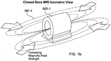
FIG. 1b is a schematic perspective view of a static magnetic field diagram of a closed bore MRI; -
FIG. 2a is a schematic top view of a static magnetic field diagram of an open bore MRI; -
FIG. 2b is a schematic isometric view of a static magnetic field diagram of an open bore MRI; -
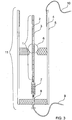
FIG. 3 is a schematic view of Magnetic field strength sensor with no external field applied; -
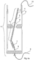
FIG. 4a is a view of the Magnetic field strength sensor ofFIG. 3 , but with a Below Threshold external magnetic field applied; -
FIG. 4b is a view of the Magnetic field strength sensor ofFIG. 3 , but with an Above Threshold external magnetic field applied; -
FIG. 5 is a schematic circuit diagram of an example alarm activation circuit; -
FIG. 6 is a schematized diagram of an example equipment mountable alarm device; and -
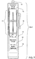
FIG. 7 is a schematized diagram of an example of a wearable alarm device. - Example embodiments that incorporate one or more aspects of the invention are described and illustrated in the drawings. These illustrated examples are not intended to be a limitation on the invention. For example, one or more aspects of the invention can be utilized in other embodiments and even other types of devices. Moreover, certain terminology is used herein for convenience only and is not to be taken as a limitation on the invention.
- A schematic example of a closed bore magnetic resonance imager (MRI) is shown within
FIGS. 1a and1b . It can be seen that that the magnetic field MF-1 surrounding the MRI magnet MR-1 is substantially horizontal. In accordance with one aspect of the present invention, in order to efficiently sense such a magnetic field a sensor could rely on a relationship that the torque on a magnet is the vector cross product of the magnetic dipole moment of the magnet and the external magnetic field. - Turning to
FIG. 3 an example of a magneticfield strength sensor 11 in accordance with an example aspect of the present invention for sensing the magnetic field ofFIGs. 1a and1b is shown. Thefield strength sensor 11 includes a sensor magnet 1 (shown in a neutral position withinFIG. 3 ) located within acylindrical housing 5. Thesensor magnet 1 may be provided as a number of smallercylindrical magnets 2 contained in an electricallyconductive tube 3. The number of the smallcylindrical magnets 2 can be changed to change the magnetic dipole moment of thesensor magnet 1. - The
sensor magnet 1 is pivotally supported by aspherical ball bearing 6, which in turn is supported upon a rotational/pivot seat that is in turn supported/fixed within thecylindrical housing 5. Theball bearing 6 is a low frictional resistance electrical insulator, such as polytetrafluoroethylene (PTFE). Within the shown example theball bearing 6 supports thesensor magnet 1 at approximately the middle of the sensor magnet. - A
bias spring 7 is attached to a bottom of thesensor magnet 1. Thespring 7 provides a biasing force that urges thesensor magnet 1 back to the neutral position shown withinFIG. 3 . Such a spring biasing force would be in opposition to force applied to thesensor magnet 1 by the external magnetic field from the MRI shown withinFIGs. 1a and1b . The spring 7 (FIG. 3 ) can be made from beryllium copper so as not to interact with the magnetic field. Since thespring 7 is on the axis of deflection of thesensor magnet 1, the balancing force for a given angle of the deflection of thesensor magnet 1 is the same without regard to the direction of deflection. Thus, the strength of the magnetic field required to close the switch is the same anywhere in the 360 field of view of the magneticfield strength sensor 11. - In turn the
spring 7 is connected to anadjustment screw 8. Theadjustment screw 8 may be rotated to change the tension within thespring 7. It is to be appreciated that thefield strength sensor 11 is adjustable to adjust sensitivity. Specifically, changing the number of smallcylindrical magnets 2 within thesensor magnet 1 can be used to as a coarse adjustment of the magnetic field strength trip point of the sensor. Fine adjustment of the magnetic field strength trip is accomplished byspring adjustment screw 8. - A
contact ring 4 is located within thehousing 5 at a location at which an upper end of the electricallyconductive tube 3 of thesensor magnet 1 may move into contact with the contact ring. Aconductive wire 9 is attached to the threshold adjustscrew 8 and awire 10 is attached to thecontact ring 4. When thesensor magnet 1 pivots under the influence of the magnetic force from the MRI and the magnetic influence is sufficiently strong to overcome the bias force of thespring 7, the upper end of theconductive tube 3 contacts the contact ring. Thus, there is electrical connection between the wire, theadjustment screw 8, theconductive tube 3, thecontact ring 4, and thewire 10. As such, the electrically connected components create a closed switch. Such a switching action can provide an indication usable as a signal. Also, the amount of magnetic force needed to displace the spring-biasedsensor magnet 1 can be selected based upon adjustment. As such the switching action is also indicative of field strength. - The
sensor magnet 1 experiences the maximum torque with thesensor magnet 1 oriented vertically when thefield strength sensor 11 is exposed to the substantially horizontal magnetic field shownFIG. 1 . Specifically, when thesensor magnet 1 in the MagneticField Strength Sensor 11 shown inFIG. 3 is brought near the MRI magnet MR-1 shown inFIG. 1 , thesensor magnet 1 will experience a torque such that thesensor magnet 1 will attempt to orient along the magnetic field lines MF-1 of the MRI magnet MR-1 shown inFIG. 1 . InFIG. 4a the rotation resulting from the torque on thesensor magnet 1 is restricted by the force of thespring 7.FIG. 4b shows the situation when thefield strength sensor 11 is brought sufficiently close to the MRI magnet MR-1 such that thesensor magnet 1, deflects to the degree necessary to bring thesensor magnet 1 in contact with the cylindricalelectrical contact ring 4. Of course it is to be appreciated that the field strength sensor may have variation of its configuration. As such,field strength sensor 11 is one example of sensing means responsive to a magnetic field and actuating in response to field strength above a predetermined threshold. It is to be appreciated that other examples of sensing means are contemplated. - Referring to
FIG. 5 , anexample activation circuit 13 is shown. Theactivation circuit 13 is operatively connected to thefield strength sensor 11 and an alarm device LS1, and is a normally open circuit that is responsive to become a closed circuit upon sensing a magnetic field strength above a certain, predetermined threshold. WithinFIG. 5 , thefield strength sensor 11 is schematically represented by S1 because the field strength sensor acts as a switch. A battery BT1 is connected in parallel to the field strength sensor (as a switch) S1 and the alarm device LS1. The alarm device LS1 is operatively connected through a transistor (e.g., Darlington) Q1 of theactivation circuit 13 to ground. The field strength sensor (as a switch) S1 is connected through a series of resistors R1 and R2 of theactivation circuit 13 to a control base of the transistor Q1, with a capacitor C1 of theactivation circuit 13 connected between a node interposed between the resistors and ground. Resistor R1 and capacitor C1 form a low pass filter to prevent transient events from activating the alarm device. Resistor R2 limits the current supplied to the Darlington transistor Q1. As such, the field strength sensor (as a switch) S1 controls operation of the transistor Q1. Accordingly, the field strength sensor (as a switch) S1 controls operation (i.e., ON-OFF) of the alarm device LS1. Of course, it is to be appreciated that theexample activation circuit 13 is just one example and is not specific limitation upon the present invention since the activation circuit could be configured differently as will be appreciated by the person of ordinary skill in the art. - When the magnetic field strength sensor S1 is open, meaning the magnetic field strength at the sensor S1 is below the trip threshold, transistor Q1 is turned off and no current flows through the alarm device LS1. Therefore there is no electrical energy being drawn from the battery BT1 when the magnetic field strength at the sensor S1 is below the trip point.
- When the magnetic field strength sensor S1 is exposed to a magnetic field strength above the predetermined trip threshold the sensor S1 closes. With the field strength sensor S1 closed, transistor Q1 is turned ON and current flows through the alarm device LS1. Also, the capacitor C1 becomes charged. When the magnetic field strength sensor S1 is moved away from the MRI magnet, the magnetic field strength will fall below the predetermined trip point, causing the magnetic field strength switch S1 to open. Since the capacitor C1 is charged, current will be supplied to transistor Q1, keeping it turned ON for a period of time dependant on the value of capacitor C1 and resistor R2. While transistor Q1 is still turned on, the alarm device will remain on. This latching function of R2 and C1 keeps short term switch S1 open periods, caused by vibration etc., from deactivating the alarm device LS1.
- With regard to the alarm device LS1, the alarm may have any of a variety of forms/configurations including audio and/or visual output. The output of Q1 may be used as an input to, for example, a patient monitor to which the present invention is attached. In this case, the display and/or the alarm of the patient monitor are used as a status indicator for the magnetic field strength level from the magnetic field strength sensor S1. The output from Q1 may also be used to activate additional safety device(s). For Example, the output from Q1 could be connected to a solenoid which, in turn, locks the wheels on the monitored cart should the cart be brought into an area considered to be a danger zone of the MRI environment. The locked wheels should discourage further movement of the cart into the danger zone of the MRI environment.
- As such, alarm device LS1 is one example of alarm means for outputting an alarm responsive to the sensing means actuation. It is to be appreciated that other examples of alarm means are contemplated. Battery BT1 is one example of energy storage means for providing electrical energy for at least the alarm means to output the alarm. It is to be appreciated that other examples of energy storage means are contemplated. The
activation circuit 13 is one example of control means for operative connection of the sensing means, the alarm means and energy storage means and for controlling provision of electrical energy such that the electrical energy is provided only when the sensing means is actuated. It is to be appreciated that other examples of control means are contemplated.
is to be appreciated that the alarm means is configured not to consume energy prior to actuation of the sensing means and only consuming energy subsequent to actuation of the sensing means. Also it is to be appreciated that the alarm means and energy storage means are operatively connected such that the electrical energy from the energy storage means is provided only when the sensing means is actuated. Also it is to be appreciated that the alarm means is configured and operatively connected to the energy storage means such that energy is not consumed by the alarm means prior to actuation of the sensing means.
shows a first example embodiment device GA1 that has at least one aspect in accordance with the present invention within an equipment mountable enclosure ME-1. With the shown example, the magneticfield strength sensor 11, theactivation circuit 13, the alarm device LS1 (which is identified within the example as audio and visual alarms 14) and the battery BT1 (which is identified within the example as UltraLife battery 12) are located within the equipment mountable enclosure ME-1. In the example, theUltraLife battery 12 is provided as a commonly available 9V battery configuration, but is a special UltraLife lithium manganese dioxide type with a 10 year service life. The use of this battery will require no replacement for up to 10 years since no power is consumed in the normal operating condition. Because of long normal operation battery life, recharging capability or RFID activation of the device are unnecessary. However, such a configuration may differ. Even when no power is being consumed, the device GA1 is capable of producing an alarm without need for turning on a power switch or other means of activation. Therefore the device GA1 can remain active and attached to medical equipment left in the MRI room for an extended period of time with no loss ofbattery 12 energy level or service life. - As previously discussed, the MRI imaging process is extremely sensitive to degradation by electromagnetic interference. Any electrical device brought into the MRI screen room can pose a risk of interference. In some of the prior art referenced, special shielding and component selection of the devices brought into the MRI screen room are used to reduce the risk of electromagnetic interference. The measures taken by the prior art reduce but do not eliminate the risk of electromagnetic interference. The present invention totally eliminates the possibility of electromagnetic interference during normal operation of the present invention. This is accomplished by removing all electric current from the present invention in the non-alarming condition. A time changing magnitude electrical current is necessary to generate electromagnetic radiation. Without a time changing magnitude electrical current or indeed any electrical current at all, there is no possibility of the present invention causing electromagnetic interference to the MRI imaging process.
-
Battery 12, as well as all the other components used, have a very low ferromagnetic content. Low ferromagnetic content of the device GA-1 ensures the product itself does not present a ferromagnetic projectile risk. - Since the magnetic
field strength sensor 11 has a 360 degree field of view with uniform magnetic field sensitivity, the device GA-1 will activate the alarm irrespective of the rotation of the piece of medical equipment to which it is attached. In some of the prior art discussed, at least 3 sensors were need to achieve a limited uniformity of magnetic field strength sensitivity over a 360 degree field of view. - Turning to
FIGS. 2a and2b , an example of an open MRI machine and associated magnetic field lines are shown. The magnetic field lines MF-2 are substantially vertical in orientation. In accordance with an aspect of the present invention, one or more embodiments will function effectively in this environment if the device is rotated 90 degrees such that the sensor magnet 1 (FIG. 3 ) is horizontal with no external magnetic field applied. For such an embodiment (i.e., horizontally oriented) theball bearing 6 is located at the center of mass of thesensor magnet 1 to remove any torque component caused by gravity. Locating theball bearing 6 at the center of mass of the magnet also eliminates any torque moment on thesensor magnet 1 from the acceleration of the medical device to which the present invention is attached. - Another embodiment in accordance with an aspect of the present invention can include 2 sensors configured such that one sensor is vertically oriented, the other is horizontally oriented. This configuration would allow ready use for either the closed bore MRI MR-1 shown in
FIGS. 1a and1b and the open bore MRI MR-2 shown inFIGS. 2a and2b without the need for the device to be rotated 90 degrees when moved from one type of MRI device to the other. -
FIG. 7 shows another embodiment of a device GA-2 in accordance with an aspect of the present invention. This device GA-2 to be worn by personnel working or otherwise exposed to the strong magnetic field of the MRI environment. This embodiment will alert the wearer and nearby personnel that wearer has entered an area of excessive magnetic strength. Numerous medical regulations as well as international safety standards limit the general public to magnetic field strengths of less than 5x10⁻⁴ T (5 gauss). The risk of exposure to excessive magnetic field strength for personnel with cardiac pacemakers, medical implants or who are pregnant is even greater. - The device GA-2 is contained in an
enclosure 15 similar to a ballpoint pen. Apocket clip 16 orients the magneticfield strength sensor 11 vertically. Alternatively, aring 17 located at a top of the enclosure allows the attachment of a lanyard to be worn around the neck. Anactivation circuit 19 is provided and the configuration may be identical or similar to theactivation circuit 13 as shown inFIG. 5 and presented inFIG. 6 . Batteries 18 (FIG. 7 ) are provided (i.e., providing the function of BT1 and shown inFIG. 5 . Thebatteries 18 may be button type batteries, which have a small compact size. Similar to the other example, audio andvisual alarms 14 are operatively connected to the magneticfield strength sensor 11, and thebatteries 18 via theactivation circuit 19. The locations, from bottom to top of the device GA-2, of thebutton batteries 18,activation circuit 19, magneticfield strength sensor 11 and audio andvisual alarms 14 are shown. However, such locations may be varied. - In addition to the MRI environment, the present invention is also applicable to other nuclear magnetic resonance (NMR) devices, such as NMR spectrometers. Some of the NMR spectrometers have magnetic field strengths in excess of 20 Tesla.
Claims (8)
- A magnetic field strength threshold system including:
a sensor responsive (11, S1) to a magnetic field, e.g. from a nuclear magnetic resonance device, and actuating in response to a strength of the magnetic field (MF-1) above a predetermined threshold, the sensor (11, S1) including:a cylindrical housing (5) including a seat support and an electrical contact ring (4);a pivotable member (3) supported by the seat support of the cylindrical housing (5) for movement through a 360° range of directions, the pivotable member (3) including a magnet (1) responsive to the magnetic field (MF-1) to cause movement of the pivotable member (3) irrespective of direction of incidence of the magnetic field and without consumption of energy provided by an energy source, the pivotable member (3) also including an electrical conductor (9), movement of the pivotable member (3) responsive to the magnetic field (MF-1) of strength above the predetermined threshold causing the electrical conductor (9) of the pivotable member (3) to electrically engage the electrical contact ring (4) of the cylindrical housing (5) so that electrical energy may flow through the electrical conductor (9) of the pivotable member (3); anda bias spring (7) being connected between the pivotable member (3) and the cylindrical housing (5) to bias the pivotable member (3) away from an engagement of the electrical conductor (9) of the pivotable member (3) to the electrical contact ring (4) of the cylindrical housing (5);wherein the pivotable member (3) includes a single spherical ball bearing (6) as a pivot point, located coincident with a center of mass of the pivotable member (3), the single spherical ball bearing (6) supported by the cylindrical housing seat support, and the bias spring (7) biasing the single spherical ball bearing (6) into engagement with the seat support; andan alarm device (LS1) operatively connected to the sensor (11, S1) and outputting an alarm, responsive to the sensor actuation, wherein the alarm device is only powered via the sensor actuation by receipt of electrical energy provided from the energy source and electrical connection proceeding through the bias spring (7), the electrical conductor (9) of the pivotable member (3) and the electrical contact ring (4) of the cylindrical housing (5) responsive to the magnetic field (MF-1) of strength above the predetermined threshold. - The magnetic field strength threshold system as set forth in claim 1, further including a circuit, operatively connected to the sensor (11, S1) and the alarm device, and an energy storage device, operatively connected to the circuit, the circuit is configured to provide electrical energy from the energy storage device to the alarm device only when the pivotable member (3) engages the electrical contact ring (4).
- The magnetic field strength threshold system as set forth in claim 1, wherein the bias spring (7) is adjustable and adjustment to the bias spring (7) changes the predetermined threshold of the strength of the magnetic field (MF-1) above which the sensor (11, S1) actuates.
- The magnetic field strength threshold system as set forth in claim 1, wherein the magnet (1) included in the pivotable member (3) comprises a number of cylindrical magnets (2), where the number of magnets (2) has an influence on the predetermined threshold of the strength of the magnetic field (MF-1) above which the sensor actuates.
- The magnetic field strength threshold system as set forth in claim 4, wherein some of the plural magnets (2) are one side of the spherical ball bearing (6) providing the pivot point and some other of the plurality of magnets (2) are located on an opposite side of the pivot point.
- The magnetic field strength threshold system as set forth in claim 1, wherein the alarm device includes at least one of an audio alarm and a visual alarm.
- The magnetic field strength threshold system as set forth in claim 1, wherein the magnetic field strength threshold system is configured to be attached to equipment that may be brought into an MRI magnet room, and which will provide an alert in response to a magnetic field (MF-1) from an MRI device within the MRI magnet room above the predetermined threshold of the strength of the magnetic field at the location of the equipment.
- The magnetic field strength threshold system as set forth in claim 1, wherein the magnetic field strength threshold system is configured to be worn by a person.
Applications Claiming Priority (2)
| Application Number | Priority Date | Filing Date | Title |
|---|---|---|---|
| US12/623,616 US8378836B2 (en) | 2009-11-23 | 2009-11-23 | Magnetic field strength threshold alarm |
| PCT/US2010/053645 WO2011062725A2 (en) | 2009-11-23 | 2010-10-22 | Magnetic field strength threshold alarm |
Publications (3)
| Publication Number | Publication Date |
|---|---|
| EP2503936A2 EP2503936A2 (en) | 2012-10-03 |
| EP2503936A4 EP2503936A4 (en) | 2013-09-04 |
| EP2503936B1 true EP2503936B1 (en) | 2018-08-22 |
Family
ID=44060259
Family Applications (1)
| Application Number | Title | Priority Date | Filing Date |
|---|---|---|---|
| EP10831960.9A Active EP2503936B1 (en) | 2009-11-23 | 2010-10-22 | Magnetic field strength threshold alarm |
Country Status (4)
| Country | Link |
|---|---|
| US (1) | US8378836B2 (en) |
| EP (1) | EP2503936B1 (en) |
| JP (1) | JP5690351B2 (en) |
| WO (1) | WO2011062725A2 (en) |
Families Citing this family (16)
| Publication number | Priority date | Publication date | Assignee | Title |
|---|---|---|---|---|
| US7553295B2 (en) | 2002-06-17 | 2009-06-30 | Iradimed Corporation | Liquid infusion apparatus |
| US8105282B2 (en) | 2007-07-13 | 2012-01-31 | Iradimed Corporation | System and method for communication with an infusion device |
| JP5658106B2 (en) * | 2011-08-01 | 2015-01-21 | 株式会社ディード | Magnetic exposure meter |
| AU2012294530B2 (en) * | 2011-08-08 | 2015-05-28 | Strata Safety Products, Llc | Proximity detection system with concurrent RF and magnetic fields |
| US20130287508A1 (en) | 2012-04-25 | 2013-10-31 | Milwaukee Electric Tool Corporation | Magnetic drill press |
| FR2993445B1 (en) * | 2012-07-23 | 2015-08-21 | Gilles Ayoun | INSTRUMENT ADAPTED TO THE MRI ENVIRONMENT SUCH AS A MR SAFE SINGLE USE LARYNGOSCOPE. |
| DE102014118597A1 (en) * | 2014-12-15 | 2016-06-16 | Dr. Hahn Gmbh & Co. Kg | Method and device for transmitting electrical power and / or signals between a wall and a wing pivotable relative to this wall |
| EP3411173B1 (en) | 2016-02-01 | 2022-11-16 | Milwaukee Electric Tool Corporation | Holding force detection for magnetic drill press |
| JP6535623B2 (en) * | 2016-03-23 | 2019-06-26 | 株式会社Nttドコモ | Broadcast signal transmitter |
| GB2556926A (en) * | 2016-11-25 | 2018-06-13 | Metrasens Ltd | Monitoring system for a detection system |
| US11268506B2 (en) | 2017-12-22 | 2022-03-08 | Iradimed Corporation | Fluid pumps for use in MRI environment |
| CN113205703B (en) * | 2020-02-03 | 2023-04-14 | 奥迪股份公司 | Driving assistance system and method for road barrier collision avoidance |
| WO2022126561A1 (en) * | 2020-12-17 | 2022-06-23 | 深圳麦科田生物医疗技术股份有限公司 | Device control system and method, electronic device, and storage medium |
| CN113274517B (en) * | 2021-05-19 | 2023-04-28 | 深圳瑞格泰科医疗科技有限公司 | Non-magnetic ultraviolet disinfection system with self-adaptive magnetic field intensity |
| EP4402517B1 (en) | 2021-09-17 | 2025-09-03 | Iradimed Corporation | Ferromagnetic detector and threat analysis |
| EP4394420A1 (en) | 2022-12-28 | 2024-07-03 | Devicor Medical Products, Inc. | Integrated excessive gauss notification for mri breast biopsy system |
Family Cites Families (28)
| Publication number | Priority date | Publication date | Assignee | Title |
|---|---|---|---|---|
| US2629792A (en) * | 1950-02-23 | 1953-02-24 | Fitch Allen & Company | Motor starting switch |
| US2898422A (en) * | 1957-09-26 | 1959-08-04 | Bell Telephone Labor Inc | Circuit controlling device |
| US2934621A (en) * | 1958-12-12 | 1960-04-26 | Donald J Stewart | Magnetic switch chopper |
| US3229063A (en) * | 1963-12-11 | 1966-01-11 | Gen Reed Company | Electromagnetic reed switch |
| GB2050610B (en) * | 1979-06-01 | 1983-12-14 | Ferranti Ltd | Accelerometer |
| US4634969A (en) * | 1984-05-14 | 1987-01-06 | The United States Of America As Represented By The Secretary Of The Army | Time varying magnetic field safety probe |
| US4910633A (en) * | 1988-09-07 | 1990-03-20 | Quinn Louis P | Magnetic levitation apparatus and method |
| US5144977A (en) * | 1991-06-20 | 1992-09-08 | Dresser Industries, Inc. | Fluid valve with actuation sensor |
| US5201128A (en) * | 1991-08-23 | 1993-04-13 | The Laitram Corporation | Miniature gimbal mounted magnetic field detectors |
| US5560115A (en) * | 1995-06-07 | 1996-10-01 | Arthur D. Little Enterprises, Inc. | Gimbaled magnetometer with inductive coupling |
| JPH09101323A (en) * | 1995-10-03 | 1997-04-15 | Tdk Corp | Acceleration sensor |
| JPH09159741A (en) * | 1995-12-05 | 1997-06-20 | Mitsubishi Electric Corp | Magnetic field display |
| JPH11248810A (en) * | 1998-02-27 | 1999-09-17 | Rikagaku Kenkyusho | Nuclear magnetic resonance equipment |
| US6087824A (en) * | 1998-03-27 | 2000-07-11 | Shiao; Hsuan-Sen | Nail locating device with magnet supporting indicator rod mounted in a ball socket |
| US6879300B2 (en) * | 2000-02-08 | 2005-04-12 | Cms Partners, Inc. | Wireless boundary proximity determining and animal containment system and method |
| US6366073B1 (en) * | 2000-05-03 | 2002-04-02 | Hsuan-Sen Shiao | Nail locating device with pivotable magnet supporting indicator rod |
| US7489128B2 (en) * | 2002-03-11 | 2009-02-10 | Kopp Keith A | MRI protector |
| US7952349B2 (en) * | 2002-12-09 | 2011-05-31 | Ferro Solutions, Inc. | Apparatus and method utilizing magnetic field |
| US7242981B2 (en) * | 2003-06-30 | 2007-07-10 | Codman Neuro Sciences Sárl | System and method for controlling an implantable medical device subject to magnetic field or radio frequency exposure |
| US7038449B1 (en) * | 2004-12-30 | 2006-05-02 | Codman & Shurtleff, Inc. | Biased magnetic field strength indication tool |
| JP2006223670A (en) * | 2005-02-18 | 2006-08-31 | Toshiba Corp | Portable device and its accessory |
| JP2006343149A (en) * | 2005-06-07 | 2006-12-21 | Chugoku Electric Power Co Inc:The | Magnetic sensor mounting structure and magnetic sensor device |
| EP1949023A4 (en) * | 2005-11-16 | 2013-02-20 | Distrib Gablex Inc | Magnetic field position sensor and method of use |
| US7696751B2 (en) * | 2005-12-08 | 2010-04-13 | Koninklijke Philips Electronics N. V. | Method and apparatus for ferrous object and/or magnetic field detection for MRI safety |
| DE102007025000B3 (en) * | 2007-05-30 | 2008-12-11 | Infineon Technologies Ag | Magnetic field sensor for monitoring wheel movement in anti-skid system of automobiles, has magnetic field sensor arrangement and magnet body |
| CN201207080Y (en) * | 2008-02-29 | 2009-03-11 | 西门子(中国)有限公司 | Magnetic field intensity indication device |
| US8416076B2 (en) * | 2008-04-02 | 2013-04-09 | The Trustees Of Dartmouth College | Magnetic proximity sensor system and associated methods of sensing a magnetic field |
| US7921571B2 (en) * | 2009-02-12 | 2011-04-12 | Sophysa | Device for mechanically locating and reading the setting of an adjustable valve |
-
2009
- 2009-11-23 US US12/623,616 patent/US8378836B2/en active Active
-
2010
- 2010-10-22 WO PCT/US2010/053645 patent/WO2011062725A2/en not_active Ceased
- 2010-10-22 JP JP2012539918A patent/JP5690351B2/en active Active
- 2010-10-22 EP EP10831960.9A patent/EP2503936B1/en active Active
Non-Patent Citations (1)
| Title |
|---|
| None * |
Also Published As
| Publication number | Publication date |
|---|---|
| JP2013511332A (en) | 2013-04-04 |
| WO2011062725A2 (en) | 2011-05-26 |
| EP2503936A2 (en) | 2012-10-03 |
| WO2011062725A3 (en) | 2011-07-21 |
| EP2503936A4 (en) | 2013-09-04 |
| US20110121986A1 (en) | 2011-05-26 |
| US8378836B2 (en) | 2013-02-19 |
| JP5690351B2 (en) | 2015-03-25 |
Similar Documents
| Publication | Publication Date | Title |
|---|---|---|
| US8378836B2 (en) | Magnetic field strength threshold alarm | |
| EP1482832B1 (en) | Mri protector | |
| KR102592177B1 (en) | Energy detection warning device | |
| US20190391213A1 (en) | Magnetic field measurement systems and methods of making and using | |
| US20090266887A1 (en) | Method and Apparatus for Ferrous Object and/or Magnetic Field Detection for MRI Safety | |
| US9802009B2 (en) | Needle magnetizing arrangement | |
| US11647928B2 (en) | Biomagnetism measuring device | |
| CN108025142B (en) | Dose control system for an injectable drug delivery device and related method of use | |
| WO2020040882A1 (en) | Magnetic field shaping components for magnetic field measurement systems and methods for making and using | |
| US9551761B2 (en) | Portable magnetic, electric and radio frequency field monitoring apparatus and method | |
| US20150369887A1 (en) | Methods and apparatuses related to instrumentation for magnetic relaxometry measurements | |
| JPH04317630A (en) | Magnetic resonance imaging system | |
| CA2864563C (en) | Hyperpolarized media transport vessel | |
| US10197644B2 (en) | Local transmit coil with integrated safety device | |
| US20190255244A1 (en) | System and method for detecting dialysis needle dislodgment | |
| US7639006B2 (en) | Detector for magnetic hazards to implanted medical device | |
| CA2972702A1 (en) | Sensitive dc current imbalance detector and calibration method | |
| JPH06121784A (en) | Magnetic field fluctuation detection device for MR imaging device | |
| EP4675300A1 (en) | Method and handheld mobile device for determining a safety hazard due to magnetic fields | |
| US20040027119A1 (en) | Device for long-term monitoring of magnetic fields | |
| JP2016142732A (en) | Magnetic sensor and magnetic property measuring device | |
| Williams et al. | Infusion pump performance in an MR environment | |
| JP5047526B2 (en) | Bias magnetic field strength indicator | |
| Ripka | Biomedical application of fluxgate sensors | |
| EP4486412A1 (en) | Magnetic coupling and detection mechanism for a pump device |
Legal Events
| Date | Code | Title | Description |
|---|---|---|---|
| PUAI | Public reference made under article 153(3) epc to a published international application that has entered the european phase |
Free format text: ORIGINAL CODE: 0009012 |
|
| 17P | Request for examination filed |
Effective date: 20120522 |
|
| AK | Designated contracting states |
Kind code of ref document: A2 Designated state(s): AL AT BE BG CH CY CZ DE DK EE ES FI FR GB GR HR HU IE IS IT LI LT LU LV MC MK MT NL NO PL PT RO RS SE SI SK SM TR |
|
| DAX | Request for extension of the european patent (deleted) | ||
| A4 | Supplementary search report drawn up and despatched |
Effective date: 20130806 |
|
| RIC1 | Information provided on ipc code assigned before grant |
Ipc: G01R 33/28 20060101ALI20130730BHEP Ipc: G01R 33/038 20060101ALI20130730BHEP Ipc: A61B 5/055 20060101ALI20130730BHEP Ipc: A61N 1/37 20060101AFI20130730BHEP |
|
| 17Q | First examination report despatched |
Effective date: 20160525 |
|
| REG | Reference to a national code |
Ref country code: DE Ref legal event code: R079 Ref document number: 602010053034 Country of ref document: DE Free format text: PREVIOUS MAIN CLASS: A61B0005055000 Ipc: G01R0033280000 |
|
| GRAP | Despatch of communication of intention to grant a patent |
Free format text: ORIGINAL CODE: EPIDOSNIGR1 |
|
| RIC1 | Information provided on ipc code assigned before grant |
Ipc: A61N 1/37 20060101ALI20180315BHEP Ipc: B82Y 25/00 20110101ALI20180315BHEP Ipc: G01R 33/28 20060101AFI20180315BHEP Ipc: G01R 33/038 20060101ALI20180315BHEP Ipc: A61B 5/055 20060101ALI20180315BHEP |
|
| INTG | Intention to grant announced |
Effective date: 20180416 |
|
| GRAS | Grant fee paid |
Free format text: ORIGINAL CODE: EPIDOSNIGR3 |
|
| GRAA | (expected) grant |
Free format text: ORIGINAL CODE: 0009210 |
|
| AK | Designated contracting states |
Kind code of ref document: B1 Designated state(s): AL AT BE BG CH CY CZ DE DK EE ES FI FR GB GR HR HU IE IS IT LI LT LU LV MC MK MT NL NO PL PT RO RS SE SI SK SM TR |
|
| REG | Reference to a national code |
Ref country code: GB Ref legal event code: FG4D |
|
| REG | Reference to a national code |
Ref country code: CH Ref legal event code: EP |
|
| REG | Reference to a national code |
Ref country code: AT Ref legal event code: REF Ref document number: 1033122 Country of ref document: AT Kind code of ref document: T Effective date: 20180915 |
|
| REG | Reference to a national code |
Ref country code: IE Ref legal event code: FG4D |
|
| REG | Reference to a national code |
Ref country code: DE Ref legal event code: R096 Ref document number: 602010053034 Country of ref document: DE |
|
| REG | Reference to a national code |
Ref country code: NL Ref legal event code: FP |
|
| REG | Reference to a national code |
Ref country code: LT Ref legal event code: MG4D |
|
| PG25 | Lapsed in a contracting state [announced via postgrant information from national office to epo] |
Ref country code: LT Free format text: LAPSE BECAUSE OF FAILURE TO SUBMIT A TRANSLATION OF THE DESCRIPTION OR TO PAY THE FEE WITHIN THE PRESCRIBED TIME-LIMIT Effective date: 20180822 Ref country code: RS Free format text: LAPSE BECAUSE OF FAILURE TO SUBMIT A TRANSLATION OF THE DESCRIPTION OR TO PAY THE FEE WITHIN THE PRESCRIBED TIME-LIMIT Effective date: 20180822 Ref country code: IS Free format text: LAPSE BECAUSE OF FAILURE TO SUBMIT A TRANSLATION OF THE DESCRIPTION OR TO PAY THE FEE WITHIN THE PRESCRIBED TIME-LIMIT Effective date: 20181222 Ref country code: NO Free format text: LAPSE BECAUSE OF FAILURE TO SUBMIT A TRANSLATION OF THE DESCRIPTION OR TO PAY THE FEE WITHIN THE PRESCRIBED TIME-LIMIT Effective date: 20181122 Ref country code: FI Free format text: LAPSE BECAUSE OF FAILURE TO SUBMIT A TRANSLATION OF THE DESCRIPTION OR TO PAY THE FEE WITHIN THE PRESCRIBED TIME-LIMIT Effective date: 20180822 Ref country code: GR Free format text: LAPSE BECAUSE OF FAILURE TO SUBMIT A TRANSLATION OF THE DESCRIPTION OR TO PAY THE FEE WITHIN THE PRESCRIBED TIME-LIMIT Effective date: 20181123 Ref country code: SE Free format text: LAPSE BECAUSE OF FAILURE TO SUBMIT A TRANSLATION OF THE DESCRIPTION OR TO PAY THE FEE WITHIN THE PRESCRIBED TIME-LIMIT Effective date: 20180822 Ref country code: BG Free format text: LAPSE BECAUSE OF FAILURE TO SUBMIT A TRANSLATION OF THE DESCRIPTION OR TO PAY THE FEE WITHIN THE PRESCRIBED TIME-LIMIT Effective date: 20181122 |
|
| REG | Reference to a national code |
Ref country code: AT Ref legal event code: MK05 Ref document number: 1033122 Country of ref document: AT Kind code of ref document: T Effective date: 20180822 |
|
| PG25 | Lapsed in a contracting state [announced via postgrant information from national office to epo] |
Ref country code: HR Free format text: LAPSE BECAUSE OF FAILURE TO SUBMIT A TRANSLATION OF THE DESCRIPTION OR TO PAY THE FEE WITHIN THE PRESCRIBED TIME-LIMIT Effective date: 20180822 Ref country code: AL Free format text: LAPSE BECAUSE OF FAILURE TO SUBMIT A TRANSLATION OF THE DESCRIPTION OR TO PAY THE FEE WITHIN THE PRESCRIBED TIME-LIMIT Effective date: 20180822 Ref country code: LV Free format text: LAPSE BECAUSE OF FAILURE TO SUBMIT A TRANSLATION OF THE DESCRIPTION OR TO PAY THE FEE WITHIN THE PRESCRIBED TIME-LIMIT Effective date: 20180822 |
|
| PG25 | Lapsed in a contracting state [announced via postgrant information from national office to epo] |
Ref country code: IT Free format text: LAPSE BECAUSE OF FAILURE TO SUBMIT A TRANSLATION OF THE DESCRIPTION OR TO PAY THE FEE WITHIN THE PRESCRIBED TIME-LIMIT Effective date: 20180822 Ref country code: RO Free format text: LAPSE BECAUSE OF FAILURE TO SUBMIT A TRANSLATION OF THE DESCRIPTION OR TO PAY THE FEE WITHIN THE PRESCRIBED TIME-LIMIT Effective date: 20180822 Ref country code: CZ Free format text: LAPSE BECAUSE OF FAILURE TO SUBMIT A TRANSLATION OF THE DESCRIPTION OR TO PAY THE FEE WITHIN THE PRESCRIBED TIME-LIMIT Effective date: 20180822 Ref country code: ES Free format text: LAPSE BECAUSE OF FAILURE TO SUBMIT A TRANSLATION OF THE DESCRIPTION OR TO PAY THE FEE WITHIN THE PRESCRIBED TIME-LIMIT Effective date: 20180822 Ref country code: AT Free format text: LAPSE BECAUSE OF FAILURE TO SUBMIT A TRANSLATION OF THE DESCRIPTION OR TO PAY THE FEE WITHIN THE PRESCRIBED TIME-LIMIT Effective date: 20180822 Ref country code: PL Free format text: LAPSE BECAUSE OF FAILURE TO SUBMIT A TRANSLATION OF THE DESCRIPTION OR TO PAY THE FEE WITHIN THE PRESCRIBED TIME-LIMIT Effective date: 20180822 Ref country code: EE Free format text: LAPSE BECAUSE OF FAILURE TO SUBMIT A TRANSLATION OF THE DESCRIPTION OR TO PAY THE FEE WITHIN THE PRESCRIBED TIME-LIMIT Effective date: 20180822 |
|
| REG | Reference to a national code |
Ref country code: DE Ref legal event code: R097 Ref document number: 602010053034 Country of ref document: DE |
|
| PG25 | Lapsed in a contracting state [announced via postgrant information from national office to epo] |
Ref country code: DK Free format text: LAPSE BECAUSE OF FAILURE TO SUBMIT A TRANSLATION OF THE DESCRIPTION OR TO PAY THE FEE WITHIN THE PRESCRIBED TIME-LIMIT Effective date: 20180822 Ref country code: SK Free format text: LAPSE BECAUSE OF FAILURE TO SUBMIT A TRANSLATION OF THE DESCRIPTION OR TO PAY THE FEE WITHIN THE PRESCRIBED TIME-LIMIT Effective date: 20180822 Ref country code: SM Free format text: LAPSE BECAUSE OF FAILURE TO SUBMIT A TRANSLATION OF THE DESCRIPTION OR TO PAY THE FEE WITHIN THE PRESCRIBED TIME-LIMIT Effective date: 20180822 |
|
| REG | Reference to a national code |
Ref country code: CH Ref legal event code: PL |
|
| REG | Reference to a national code |
Ref country code: BE Ref legal event code: MM Effective date: 20181031 |
|
| PG25 | Lapsed in a contracting state [announced via postgrant information from national office to epo] |
Ref country code: LU Free format text: LAPSE BECAUSE OF NON-PAYMENT OF DUE FEES Effective date: 20181022 Ref country code: MC Free format text: LAPSE BECAUSE OF FAILURE TO SUBMIT A TRANSLATION OF THE DESCRIPTION OR TO PAY THE FEE WITHIN THE PRESCRIBED TIME-LIMIT Effective date: 20180822 |
|
| PLBE | No opposition filed within time limit |
Free format text: ORIGINAL CODE: 0009261 |
|
| STAA | Information on the status of an ep patent application or granted ep patent |
Free format text: STATUS: NO OPPOSITION FILED WITHIN TIME LIMIT |
|
| REG | Reference to a national code |
Ref country code: IE Ref legal event code: MM4A |
|
| 26N | No opposition filed |
Effective date: 20190523 |
|
| PG25 | Lapsed in a contracting state [announced via postgrant information from national office to epo] |
Ref country code: FR Free format text: LAPSE BECAUSE OF NON-PAYMENT OF DUE FEES Effective date: 20181022 Ref country code: LI Free format text: LAPSE BECAUSE OF NON-PAYMENT OF DUE FEES Effective date: 20181031 Ref country code: CH Free format text: LAPSE BECAUSE OF NON-PAYMENT OF DUE FEES Effective date: 20181031 Ref country code: SI Free format text: LAPSE BECAUSE OF FAILURE TO SUBMIT A TRANSLATION OF THE DESCRIPTION OR TO PAY THE FEE WITHIN THE PRESCRIBED TIME-LIMIT Effective date: 20180822 Ref country code: BE Free format text: LAPSE BECAUSE OF NON-PAYMENT OF DUE FEES Effective date: 20181031 |
|
| PG25 | Lapsed in a contracting state [announced via postgrant information from national office to epo] |
Ref country code: IE Free format text: LAPSE BECAUSE OF NON-PAYMENT OF DUE FEES Effective date: 20181022 |
|
| PG25 | Lapsed in a contracting state [announced via postgrant information from national office to epo] |
Ref country code: MT Free format text: LAPSE BECAUSE OF NON-PAYMENT OF DUE FEES Effective date: 20181022 |
|
| PG25 | Lapsed in a contracting state [announced via postgrant information from national office to epo] |
Ref country code: TR Free format text: LAPSE BECAUSE OF FAILURE TO SUBMIT A TRANSLATION OF THE DESCRIPTION OR TO PAY THE FEE WITHIN THE PRESCRIBED TIME-LIMIT Effective date: 20180822 |
|
| PG25 | Lapsed in a contracting state [announced via postgrant information from national office to epo] |
Ref country code: PT Free format text: LAPSE BECAUSE OF FAILURE TO SUBMIT A TRANSLATION OF THE DESCRIPTION OR TO PAY THE FEE WITHIN THE PRESCRIBED TIME-LIMIT Effective date: 20180822 |
|
| PG25 | Lapsed in a contracting state [announced via postgrant information from national office to epo] |
Ref country code: MK Free format text: LAPSE BECAUSE OF NON-PAYMENT OF DUE FEES Effective date: 20180822 Ref country code: HU Free format text: LAPSE BECAUSE OF FAILURE TO SUBMIT A TRANSLATION OF THE DESCRIPTION OR TO PAY THE FEE WITHIN THE PRESCRIBED TIME-LIMIT; INVALID AB INITIO Effective date: 20101022 Ref country code: CY Free format text: LAPSE BECAUSE OF FAILURE TO SUBMIT A TRANSLATION OF THE DESCRIPTION OR TO PAY THE FEE WITHIN THE PRESCRIBED TIME-LIMIT Effective date: 20180822 |
|
| PGFP | Annual fee paid to national office [announced via postgrant information from national office to epo] |
Ref country code: NL Payment date: 20251021 Year of fee payment: 16 |
|
| PGFP | Annual fee paid to national office [announced via postgrant information from national office to epo] |
Ref country code: DE Payment date: 20251021 Year of fee payment: 16 |
|
| PGFP | Annual fee paid to national office [announced via postgrant information from national office to epo] |
Ref country code: GB Payment date: 20251022 Year of fee payment: 16 |