EP2503712A1 - Hybrid electrical/optical splitting oeo pon - Google Patents
Hybrid electrical/optical splitting oeo pon Download PDFInfo
- Publication number
- EP2503712A1 EP2503712A1 EP11290141A EP11290141A EP2503712A1 EP 2503712 A1 EP2503712 A1 EP 2503712A1 EP 11290141 A EP11290141 A EP 11290141A EP 11290141 A EP11290141 A EP 11290141A EP 2503712 A1 EP2503712 A1 EP 2503712A1
- Authority
- EP
- European Patent Office
- Prior art keywords
- optical
- point
- electrical
- extender
- downlink
- Prior art date
- Legal status (The legal status is an assumption and is not a legal conclusion. Google has not performed a legal analysis and makes no representation as to the accuracy of the status listed.)
- Granted
Links
- 230000003287 optical effect Effects 0.000 title claims abstract description 156
- 239000004606 Fillers/Extenders Substances 0.000 claims abstract description 58
- 230000005540 biological transmission Effects 0.000 claims abstract description 17
- 238000011144 upstream manufacturing Methods 0.000 claims description 9
- 238000007493 shaping process Methods 0.000 claims description 3
- 239000013307 optical fiber Substances 0.000 claims 1
- 239000000835 fiber Substances 0.000 description 13
- 238000000034 method Methods 0.000 description 6
- 238000006243 chemical reaction Methods 0.000 description 5
- 238000010586 diagram Methods 0.000 description 3
- 238000003199 nucleic acid amplification method Methods 0.000 description 3
- 230000003321 amplification Effects 0.000 description 1
- 238000000098 azimuthal photoelectron diffraction Methods 0.000 description 1
- 230000010354 integration Effects 0.000 description 1
- 230000008929 regeneration Effects 0.000 description 1
- 238000011069 regeneration method Methods 0.000 description 1
- 230000035945 sensitivity Effects 0.000 description 1
- 230000007704 transition Effects 0.000 description 1
Images

Classifications
-
- H—ELECTRICITY
- H04—ELECTRIC COMMUNICATION TECHNIQUE
- H04B—TRANSMISSION
- H04B10/00—Transmission systems employing electromagnetic waves other than radio-waves, e.g. infrared, visible or ultraviolet light, or employing corpuscular radiation, e.g. quantum communication
- H04B10/29—Repeaters
- H04B10/291—Repeaters in which processing or amplification is carried out without conversion of the main signal from optical form
- H04B10/298—Two-way repeaters, i.e. repeaters amplifying separate upward and downward lines
-
- H—ELECTRICITY
- H04—ELECTRIC COMMUNICATION TECHNIQUE
- H04Q—SELECTING
- H04Q2213/00—Indexing scheme relating to selecting arrangements in general and for multiplex systems
- H04Q2213/1301—Optical transmission, optical switches
Definitions
- the present document relates to optical transmission systems.
- the present document relates to a reach extender for passive optical networks (PON).
- PON passive optical networks
- PON Current Passive Optical Networks
- PON typically comprise a relatively long feeder fiber, a passive optical splitter and a plurality of shorter drop fibers.
- the reach and splitting ratio of a PON is limited. If the reach and splitting ratio of such PONs is to be increased, special midspan reach extenders may be used.
- optical amplifiers For reach extension of such PONs (e.g. GPONs) either optical amplifiers or Optical/Electrical/Optical reach extenders (e.g. according to ITU-T G.984.6) may be used. These devices typically have one input port, e.g. for the feeder fiber, and one output port. The optical power splitter is typically connected to the output port of a reach extender. The fact that the optical power splitter is connected to the output port of the reach extender may limit the achievable optical budget. In order to increase the achievable optical budget an electrically splitting OEO (optical-electrical-optical) converter may be used. This device makes the splitting in the electrical regime and uses point to point links for the drop section. With this approach the splitting factor is theoretically infinite and the optical budget is increased as well. These electrically splitting OEOs are protocol agnostic and are typically doing 2R regeneration (i.e. re-amplification and re-shaping of the signal). On the other hand, electrically splitting OEO converters tend to be relatively cost
- the present document describes a cost effective reach extender for passive optical networks which allows for an increased optical budget.
- a point to multipoint (ptmp) reach extender e.g. an optical-electrical-optical (oeo) extender
- the extender may be used in passive optical networks (PON) such as Gigabit PON (GPON) or wavelength division multiplex (WDM) PON.
- PON passive optical networks
- GPON Gigabit PON
- WDM wavelength division multiplex
- Such a PON may comprise an optical line terminal (OLT) at a network side, e.g. at a central office of the network provider.
- the PON may comprise a plurality of optical network terminals (ONT) or optical network units (ONU) at a customer premise side.
- the PON may comprise a feeder optical transmission channel, e.g. a feeder fiber, linked to the OLT, as well as a plurality of drop optical transmission channels, e.g. a plurality of drop fibers, linked to the plurality of ONTs, respectively.
- the extender may comprise a point-to-point (ptp) optical amplifier, e.g. an optical-electrical-optical (oeo) converter, configured to amplify an optical downlink feeder signal on the feeder optical transmission channel on the downlink from the OLT to the plurality of ONTs, thereby yielding an amplified optical downlink signal.
- ptp point-to-point
- the downlink feeder signal on the feeder optical transmission channel e.g. on the feeder fiber
- Such amplification may be performed prior to the splitting of the amplified optical downlink feeder signal towards the plurality of ONTs.
- the extender may comprise a multipoint-to-point (mptp) optical amplifier and multiplexer, e.g. an optical-electrical-optical (oeo) converter, configured to amplify and/or multiplex a plurality of optical uplink drop signals on an uplink from the plurality of optical network terminals to the optical line terminal.
- mptp multipoint-to-point
- multiplexer e.g. an optical-electrical-optical (oeo) converter
- the plurality of optical uplink drop signals on the respective plurality of drop optical transmission channels may be amplified and/or multiplexed in order to provide an uplink feeder signal on the uplink of the feeder optical transmission channel to the OLT.
- the extender may further comprise a point-to-multipoint passive optical splitter configured to distribute the amplified optical downlink feeder signal to the plurality of ONTs, thereby yielding a plurality of optical downlink drop signals.
- a point-to-multipoint passive optical splitter configured to distribute the amplified optical downlink feeder signal to the plurality of ONTs, thereby yielding a plurality of optical downlink drop signals. This means that on the downlink direction of the PON, the optical downlink feeder signal may be optically amplified prior to being optically split into a plurality of optical downlink drop signals which are provided to the respective plurality of ONTs.
- the extender may further comprise a plurality of diplexers configured to multiplex the plurality of optical downlink drop signals onto the plurality of drop optical transmission channels, e.g. the plurality of optical drop fibers, to the respective plurality of optical network terminals.
- the plurality of diplexers may be configured to de-multiplex the plurality of optical uplink drop signals from the plurality of drop optical transmission channels, respectively.
- the diplexers may be implemented as optical filters configured to isolate and/or merge the wavelength range of the plurality of optical downlink drop signals, as well as the wavelength range of the plurality of optical uplink drop signals.
- the wavelength range of the plurality of optical downlink drop signals may be 1480nm to 1500nm and the wavelength range of the plurality of optical uplink drop signals may be 1290nm to 1330nm.
- the point-to-multipoint passive optical splitter and the plurality of diplexers may be implemented on a common photonic lightwave circuit (PLC) or a common photonic integrated circuit (PIC).
- PLC common photonic lightwave circuit
- PIC common photonic integrated circuit
- the PLC or PIC may be a passive photonic circuit.
- the ptp optical amplifier on the downlink may comprise an optical-to-electrical (OE) converter configured to convert the optical downlink feeder signal to an electrical downlink feeder signal.
- OE optical-to-electrical
- the electrical downlink feeder signal may be re-amplified and/or re-shaped within the ptp optical amplifier.
- the ptp optical amplifier, e.g. the point-to-point optical-electrical-optical converter may comprise a laser configured to convert the (amplified and/or reshaped) electrical downlink feeder signal to the amplified optical downlink feeder signal.
- the laser may be a distributed feedback laser.
- the extender may comprise a ptp optical amplifier followed by an optical splitter on the downlink direction of the PON from the OLT to the plurality of ONTs.
- Such a configuration is particularly cost efficient for the optical downlink feeder signal which is broadcasted to the plurality of ONTs, while providing the optical budgets required for typical PONs.
- the mptp optical amplifier and multiplexer, e.g. the multipoint-to-point optical-electrical-optical converter, on the uplink from the plurality of ONTs to the OLT may comprise a plurality of OE converters configured to convert the plurality of optical uplink drop signals to a plurality of electrical uplink drop signals.
- the plurality of OE converters may be a plurality of photodiodes, e.g. PIN diodes.
- the mptp optical amplifier and multiplexer may further comprise a multiplexer configured to multiplex the plurality of electrical uplink drop signals onto an electrical uplink feeder signal. Furthermore, the mptp optical amplifier and multiplexer may perform re-amplification and re-shaping of the plurality of electrical uplink drop signals and/or of the electrical uplink feeder signal. In addition, the mptp optical amplifier and multiplexer, e.g. the multipoint-to-point optical-electrical-optical converter, may comprise an electrical-to-optical converter configured to convert the electrical uplink feeder signal into an optical uplink feeder signal on the uplink of the feeder optical transmission channel to the optical line terminal.
- the extender may comprise a mptp optical amplifier and multiplexer comprising an electrical multiplexer on the uplink from the plurality of ONTs to the OLT.
- a reach extender which may use optical splitting on the downstream of the PON from the OLT to the plurality of ONTs and electrical multiplexing on the upstream of the PON from the plurality of ONTs to the OLT.
- a passive optical network may comprise an optical line terminal and a plurality of optical network terminals.
- the PON may comprise a reach extender according to any of the features and aspects outlined in the present document.
- the reach extender may be positioned downstream of the optical line terminal and upstream of the plurality of optical network terminals.
- Fig. 1 illustrates two example passive optical networks comprising Optical/Electrical/Optical reach extenders.
- the upper network 100 comprises a point-to-multi-point OEO extender 111, which comprises an electrical splitting unit 113.
- the point-to-multi-point OEO extender 111 links the optical line terminal (OLT) 101 with a plurality of optical network terminals (ONT) 102.
- the OLT 101 is connected to an O/E converter 112 of the point-to-multi-point OEO extender 111.
- the O/E converter 112 performs an optical-to-electrical conversion on the downlink from the OLT 101 to the plurality of ONTs 102.
- the O/E converter 112 performs an electrical-to-optical conversion on the uplink from the plurality of ONTs 102 to the OLT 101.
- each of the ONTs 102 is connected to an E/O converter 114 of the point-to-multi-point OEO extender 111 via a respective drop fiber.
- the E/O converter 114 performs an electrical-to-optical conversion on the downlink from the OLT 101 to the respective ONT 102. Furthermore, the E/O converter 114 performs an optical-to-electrical conversion on the uplink from the respective ONT 102 to the OLT 101.
- the point-to-multi-point OEO extender 111 also comprises an electrical splitting unit 113 which is configured to pass the electrical signal on the downlink from the OLT 101 to the plurality of ONTs 102 to each of the plurality of ONTs 102. Furthermore, the electrical splitting unit 113 is configured to multiplex the plurality of electrical signals on the uplink from the respective plurality of ONTs 102 to the OLT 101 onto a single electrical signal entering the O/E converter 112.
- Fig. 1 also illustrates a PON 120 comprising a point-to-point O/E/O reach extender 121.
- the point-to-point O/E/O reach extender 121 is positioned on the feeder fiber between the OLT 101 and the optical splitter 123.
- the point-to-point O/E/O reach extender 121 is configured to amplify an optical signal on the downlink and/or on the uplink between the OLT 101 and the plurality of ONTs 102.
- the electrical splitting OEO approach used in network 100 of Fig. 1 has the disadvantage of using nearly double as many OE conversion modules 112, 114 than the optical splitting approach of network 120 of Fig. 1 .
- a possible approach to cost reduction could be to reduce the cost of the optical modules by using lower performance transmitters and receiver, e.g. PIN diodes instead of APDs (avalanche photodiodes) and low power lasers instead of high power lasers in the electrically splitting OEO and in the ONTs.
- PIN diodes instead of APDs (avalanche photodiodes)
- low power lasers instead of high power lasers in the electrically splitting OEO and in the ONTs.
- the relatively high number of additional components required for a point-to-multimode OEO reach extender 111 limits the overall possibilities for cost reduction.
- the present document suggests a modified architecture of a splitting OEO reach extender.
- a hybrid electrical and optical splitting OEO solution 200 is proposed and described in the context of Fig. 2 .
- the OEO reach extender solution 200 of Fig. 2 allows for a reduction of the number of required components and thereby allows for cost reduction while keeping a high performance with regards to the optical link budget and the achievable splitting ratio.
- Low cost PIN diode receivers for GPON downstream traffic (2.5Gbit/s) used within the ONTs 102 have sensitivities of about -18dBm.
- Typical lengths of the drop fibers between the splitter and the ONTs 102 are less than 10km which corresponds to less than 4dB attenuation. This means that even when using low cost and low power lasers within the E/O converters 114 on the downlink from the OLT 101 to an ONT 102, the components on the point-to-point link between E/O converter 114 and ONT 102 are much too powerful for the required point-to-point reach of the downstream broadcating.
- one laser could be sufficient for performing the reach extension.
- one low cost laser may be sufficient to transmit the optical signal on the downstream to approx. 8-16 ONTs.
- one downstream laser 230 may be shared using optical power splitters 223 for approx. 8-16 ONTs.
- the point-to-multi-point OEO reach extender 111 may be replaced by a point-to-point OEO reach extender 121 on the downlink from the OLT 101 to the plurality of ONTs 102.
- an optical signal on the feeder fiber 250 on the downlink may be amplified by an OEO reach extender comprising an O/E converter 212 configured to convert the optical downlink signal into an electrical downlink signal, and an E/O converter 230 (e.g. a laser) configured to convert the electrical downlink signal into an amplified optical downlink signal 251.
- the optical signal on the downlink may be 2R regenerated prior to entering the optical splitter 223 which splits the optical signal 251 into a plurality of optical drop signals 253 on the downlink towards the respective plurality of ONTs 102.
- the use of a single O/E converter may not be useful, because this would require the use of relatively sophisticated burst mode receiver capabilities.
- the plurality of optical upstream signals 255 may be converted into a plurality of electrical signals which may be multiplexed by the electrical multiplexer 213.
- the electrically multiplexed signal may then be converted by the O/E converter 212 into an optical upstream signal on the feeder fiber 250 towards the OLT 101.
- the hybrid scenario 200 of Fig. 2 requires only few additional optical components compared to a PON without any reach extender.
- just one low cost PIN receiver 214 is required on the upstream direction and only a fraction, e.g. 1/8 or 1/16, of a laser 230 is required on the downstream.
- Up and downstream links may be combined using a diplexer 231.
- the diplexer 231 may combine and/or separate the downstream optical signal 253 and the upstream optical signal 255 to and/or from the drop fiber 254.
- optical integration on a photonic integrated circuit may be used.
- the optical splitter 223 and the plurality of diplexers 231 may be implemented on a joint PIC 240.
- any block diagrams herein represent conceptual views of illustrative circuitry embodying the principles of the invention.
- any flow charts, flow diagrams, state transition diagrams, pseudo code, and the like represent various processes which may be substantially represented in computer readable medium and so executed by a computer or processor, whether or not such computer or processor is explicitly shown.
Landscapes
- Physics & Mathematics (AREA)
- Electromagnetism (AREA)
- Engineering & Computer Science (AREA)
- Computer Networks & Wireless Communication (AREA)
- Signal Processing (AREA)
- Optical Communication System (AREA)
- Small-Scale Networks (AREA)
Abstract
Description
- The present document relates to optical transmission systems. In particular, the present document relates to a reach extender for passive optical networks (PON).
- Current Passive Optical Networks (PON) typically comprise a relatively long feeder fiber, a passive optical splitter and a plurality of shorter drop fibers. The reach and splitting ratio of a PON is limited. If the reach and splitting ratio of such PONs is to be increased, special midspan reach extenders may be used.
- For reach extension of such PONs (e.g. GPONs) either optical amplifiers or Optical/Electrical/Optical reach extenders (e.g. according to ITU-T G.984.6) may be used. These devices typically have one input port, e.g. for the feeder fiber, and one output port. The optical power splitter is typically connected to the output port of a reach extender. The fact that the optical power splitter is connected to the output port of the reach extender may limit the achievable optical budget. In order to increase the achievable optical budget an electrically splitting OEO (optical-electrical-optical) converter may be used. This device makes the splitting in the electrical regime and uses point to point links for the drop section. With this approach the splitting factor is theoretically infinite and the optical budget is increased as well. These electrically splitting OEOs are protocol agnostic and are typically doing 2R regeneration (i.e. re-amplification and re-shaping of the signal). On the other hand, electrically splitting OEO converters tend to be relatively cost intensive
- The present document describes a cost effective reach extender for passive optical networks which allows for an increased optical budget.
- According to an aspect, a point to multipoint (ptmp) reach extender, e.g. an optical-electrical-optical (oeo) extender, for a passive optical network is described. The extender may be used in passive optical networks (PON) such as Gigabit PON (GPON) or wavelength division multiplex (WDM) PON. Such a PON may comprise an optical line terminal (OLT) at a network side, e.g. at a central office of the network provider. Furthermore, the PON may comprise a plurality of optical network terminals (ONT) or optical network units (ONU) at a customer premise side. In addition, the PON may comprise a feeder optical transmission channel, e.g. a feeder fiber, linked to the OLT, as well as a plurality of drop optical transmission channels, e.g. a plurality of drop fibers, linked to the plurality of ONTs, respectively.
- The extender may comprise a point-to-point (ptp) optical amplifier, e.g. an optical-electrical-optical (oeo) converter, configured to amplify an optical downlink feeder signal on the feeder optical transmission channel on the downlink from the OLT to the plurality of ONTs, thereby yielding an amplified optical downlink signal. In other words, on the downlink from the OLT to the plurality of ONTs, the downlink feeder signal on the feeder optical transmission channel (e.g. on the feeder fiber) may be amplified by a ptp optical amplifier. Such amplification may be performed prior to the splitting of the amplified optical downlink feeder signal towards the plurality of ONTs.
- The extender may comprise a multipoint-to-point (mptp) optical amplifier and multiplexer, e.g. an optical-electrical-optical (oeo) converter, configured to amplify and/or multiplex a plurality of optical uplink drop signals on an uplink from the plurality of optical network terminals to the optical line terminal. In other words, on an uplink direction of the PON from the plurality of ONTs towards the OLT, the plurality of optical uplink drop signals on the respective plurality of drop optical transmission channels may be amplified and/or multiplexed in order to provide an uplink feeder signal on the uplink of the feeder optical transmission channel to the OLT.
- The extender may further comprise a point-to-multipoint passive optical splitter configured to distribute the amplified optical downlink feeder signal to the plurality of ONTs, thereby yielding a plurality of optical downlink drop signals. This means that on the downlink direction of the PON, the optical downlink feeder signal may be optically amplified prior to being optically split into a plurality of optical downlink drop signals which are provided to the respective plurality of ONTs.
- The extender may further comprise a plurality of diplexers configured to multiplex the plurality of optical downlink drop signals onto the plurality of drop optical transmission channels, e.g. the plurality of optical drop fibers, to the respective plurality of optical network terminals. In addition, the plurality of diplexers may be configured to de-multiplex the plurality of optical uplink drop signals from the plurality of drop optical transmission channels, respectively. The diplexers may be implemented as optical filters configured to isolate and/or merge the wavelength range of the plurality of optical downlink drop signals, as well as the wavelength range of the plurality of optical uplink drop signals. By way of example, the wavelength range of the plurality of optical downlink drop signals may be 1480nm to 1500nm and the wavelength range of the plurality of optical uplink drop signals may be 1290nm to 1330nm.
- The point-to-multipoint passive optical splitter and the plurality of diplexers may be implemented on a common photonic lightwave circuit (PLC) or a common photonic integrated circuit (PIC). The PLC or PIC may be a passive photonic circuit.
- The ptp optical amplifier on the downlink, e.g. the point-to-point optical-electrical-optical converter, may comprise an optical-to-electrical (OE) converter configured to convert the optical downlink feeder signal to an electrical downlink feeder signal. Such an OE converter may be implemented as a photodiode. The electrical downlink feeder signal may be re-amplified and/or re-shaped within the ptp optical amplifier. Furthermore, the ptp optical amplifier, e.g. the point-to-point optical-electrical-optical converter, may comprise a laser configured to convert the (amplified and/or reshaped) electrical downlink feeder signal to the amplified optical downlink feeder signal. The laser may be a distributed feedback laser.
- As such, the extender may comprise a ptp optical amplifier followed by an optical splitter on the downlink direction of the PON from the OLT to the plurality of ONTs. Such a configuration is particularly cost efficient for the optical downlink feeder signal which is broadcasted to the plurality of ONTs, while providing the optical budgets required for typical PONs.
- The mptp optical amplifier and multiplexer, e.g. the multipoint-to-point optical-electrical-optical converter, on the uplink from the plurality of ONTs to the OLT may comprise a plurality of OE converters configured to convert the plurality of optical uplink drop signals to a plurality of electrical uplink drop signals. The plurality of OE converters may be a plurality of photodiodes, e.g. PIN diodes.
- The mptp optical amplifier and multiplexer, e.g. the multipoint-to-point optical-electrical-optical converter, may further comprise a multiplexer configured to multiplex the plurality of electrical uplink drop signals onto an electrical uplink feeder signal. Furthermore, the mptp optical amplifier and multiplexer may perform re-amplification and re-shaping of the plurality of electrical uplink drop signals and/or of the electrical uplink feeder signal. In addition, the mptp optical amplifier and multiplexer, e.g. the multipoint-to-point optical-electrical-optical converter, may comprise an electrical-to-optical converter configured to convert the electrical uplink feeder signal into an optical uplink feeder signal on the uplink of the feeder optical transmission channel to the optical line terminal.
- As such, the extender may comprise a mptp optical amplifier and multiplexer comprising an electrical multiplexer on the uplink from the plurality of ONTs to the OLT. This is a cost efficient approach to providing the required optical budget for the plurality of optical uplink drop signals from the plurality of ONTs to the OLT.
- Overall, a reach extender is described which may use optical splitting on the downstream of the PON from the OLT to the plurality of ONTs and electrical multiplexing on the upstream of the PON from the plurality of ONTs to the OLT.
- According to a further aspect, a passive optical network is described. The PON may comprise an optical line terminal and a plurality of optical network terminals. Furthermore, the PON may comprise a reach extender according to any of the features and aspects outlined in the present document. The reach extender may be positioned downstream of the optical line terminal and upstream of the plurality of optical network terminals.
- It should be noted that the methods and systems including its preferred embodiments as outlined in the present patent application may be used stand-alone or in combination with the other methods and systems disclosed in this document. Furthermore, all aspects of the methods and systems outlined in the present patent application may be arbitrarily combined. In particular, the features of the claims may be combined with one another in an arbitrary manner.
- The claimed subject-matter is explained below in an exemplary manner with reference to the accompanying drawings, wherein
-
Fig. 1 illustrates example PONs comprising Optical/Electrical/Optical reach extenders; and -
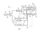
Fig. 2 illustrates an example hybrid reach extender for passive optical networks. -
Fig. 1 illustrates two example passive optical networks comprising Optical/Electrical/Optical reach extenders. Theupper network 100 comprises a point-to-multi-point OEO extender 111, which comprises anelectrical splitting unit 113. The point-to-multi-point OEO extender 111 links the optical line terminal (OLT) 101 with a plurality of optical network terminals (ONT) 102. The OLT 101 is connected to an O/E converter 112 of the point-to-multi-point OEO extender 111. The O/E converter 112 performs an optical-to-electrical conversion on the downlink from theOLT 101 to the plurality ofONTs 102. Furthermore, the O/E converter 112 performs an electrical-to-optical conversion on the uplink from the plurality ofONTs 102 to theOLT 101. - In a similar manner, each of the
ONTs 102 is connected to an E/O converter 114 of the point-to-multi-point OEO extender 111 via a respective drop fiber. The E/O converter 114 performs an electrical-to-optical conversion on the downlink from theOLT 101 to therespective ONT 102. Furthermore, the E/O converter 114 performs an optical-to-electrical conversion on the uplink from therespective ONT 102 to theOLT 101. - As already indicated above, the point-to-
multi-point OEO extender 111 also comprises anelectrical splitting unit 113 which is configured to pass the electrical signal on the downlink from theOLT 101 to the plurality ofONTs 102 to each of the plurality ofONTs 102. Furthermore, theelectrical splitting unit 113 is configured to multiplex the plurality of electrical signals on the uplink from the respective plurality ofONTs 102 to theOLT 101 onto a single electrical signal entering the O/E converter 112. -
Fig. 1 also illustrates aPON 120 comprising a point-to-point O/E/O reach extender 121. The point-to-point O/E/O reach extender 121 is positioned on the feeder fiber between theOLT 101 and theoptical splitter 123. The point-to-point O/E/O reach extender 121 is configured to amplify an optical signal on the downlink and/or on the uplink between theOLT 101 and the plurality ofONTs 102. - The electrical splitting OEO approach used in
network 100 ofFig. 1 has the disadvantage of using nearly double as manyOE conversion modules network 120 ofFig. 1 . This could be challenging with regards to the cost of the overall PON system. A possible approach to cost reduction could be to reduce the cost of the optical modules by using lower performance transmitters and receiver, e.g. PIN diodes instead of APDs (avalanche photodiodes) and low power lasers instead of high power lasers in the electrically splitting OEO and in the ONTs. Furthermore, the relatively high number of additional components required for a point-to-multimodeOEO reach extender 111 limits the overall possibilities for cost reduction. - In order to allow for a cost reduction, while keeping a good optical link budget and splitting ratio, the present document suggests a modified architecture of a splitting OEO reach extender. In particular, a hybrid electrical and optical
splitting OEO solution 200 is proposed and described in the context ofFig. 2 . The OEOreach extender solution 200 ofFig. 2 allows for a reduction of the number of required components and thereby allows for cost reduction while keeping a high performance with regards to the optical link budget and the achievable splitting ratio. - It should be noted that even a low cost and low power laser has an output power in the range of 1mW. Low cost PIN diode receivers for GPON downstream traffic (2.5Gbit/s) used within the
ONTs 102 have sensitivities of about -18dBm. Typical lengths of the drop fibers between the splitter and theONTs 102 are less than 10km which corresponds to less than 4dB attenuation. This means that even when using low cost and low power lasers within the E/O converters 114 on the downlink from theOLT 101 to anONT 102, the components on the point-to-point link between E/O converter 114 andONT 102 are much too powerful for the required point-to-point reach of the downstream broadcating. Consequently, for the downstream direction from theOLT 101 to the plurality ofONTs 102, one laser could be sufficient for performing the reach extension. In particular, one low cost laser may be sufficient to transmit the optical signal on the downstream to approx. 8-16 ONTs. This means that onedownstream laser 230 may be shared usingoptical power splitters 223 for approx. 8-16 ONTs. - In other words, the point-to-multi-point
OEO reach extender 111 may be replaced by a point-to-pointOEO reach extender 121 on the downlink from theOLT 101 to the plurality ofONTs 102. This means that an optical signal on thefeeder fiber 250 on the downlink may be amplified by an OEO reach extender comprising an O/E converter 212 configured to convert the optical downlink signal into an electrical downlink signal, and an E/O converter 230 (e.g. a laser) configured to convert the electrical downlink signal into an amplifiedoptical downlink signal 251. As a result of such point-to-point OEO reach extension, the optical signal on the downlink may be 2R regenerated prior to entering theoptical splitter 223 which splits theoptical signal 251 into a plurality of optical drop signals 253 on the downlink towards the respective plurality ofONTs 102. - In the upstream direction, the use of a single O/E converter (similar to the O/E converter in the point-to-point OEO reach extender 121) may not be useful, because this would require the use of relatively sophisticated burst mode receiver capabilities. As such, it is suggested to feed the plurality of ONTs 102 (e.g. approx 8-16 ONTs) on the upstream link to separate
PIN receivers 214 in the hybridOEO reach extender 200. In other words, it is proposed to use a point-to-multi-pointOEO reach extender 111 on the uplink from the plurality ofONTs 102 to theOLT 101. As such, the plurality of opticalupstream signals 255 may be converted into a plurality of electrical signals which may be multiplexed by theelectrical multiplexer 213. The electrically multiplexed signal may then be converted by the O/E converter 212 into an optical upstream signal on thefeeder fiber 250 towards theOLT 101. - This means that the
hybrid scenario 200 ofFig. 2 requires only few additional optical components compared to a PON without any reach extender. In particular, just one lowcost PIN receiver 214 is required on the upstream direction and only a fraction, e.g. 1/8 or 1/16, of alaser 230 is required on the downstream. - Up and downstream links may be combined using a
diplexer 231. In particular, thediplexer 231 may combine and/or separate the downstreamoptical signal 253 and the upstreamoptical signal 255 to and/or from thedrop fiber 254. - The above mentioned approach is especially attractive, if optical integration on a photonic integrated circuit (PIC) may be used. In particular, the
optical splitter 223 and the plurality ofdiplexers 231 may be implemented on ajoint PIC 240. - In the present document a reach extender for a PON has been described which allows a high splitting ratio and/or optical budget at little additional cost. The described electrically splitting OEO repeater is cost optimized without impairing the performance compared to conventional OEO repeater solutions.
- It should be noted that the description and drawings merely illustrate the principles of the proposed methods and systems. It will thus be appreciated that those skilled in the art will be able to devise various arrangements that, although not explicitly described or shown herein, embody the principles of the invention and are included within its spirit and scope. Furthermore, all examples recited herein are principally intended expressly to be only for pedagogical purposes to aid the reader in understanding the principles of the proposed methods and systems and the concepts contributed by the inventors to furthering the art, and are to be construed as being without limitation to such specifically recited examples and conditions. Moreover, all statements herein reciting principles, aspects, and embodiments of the invention, as well as specific examples thereof, are intended to encompass equivalents thereof.
- In addition, it should be noted that the functions of the various elements described in the present patent document may be provided through the use of dedicated hardware as well as hardware capable of executing software in association with appropriate software.
- Finally, it should be noted that any block diagrams herein represent conceptual views of illustrative circuitry embodying the principles of the invention. Similarly, it will be appreciated that any flow charts, flow diagrams, state transition diagrams, pseudo code, and the like represent various processes which may be substantially represented in computer readable medium and so executed by a computer or processor, whether or not such computer or processor is explicitly shown.
Claims (15)
- A point to multipoint reach extender (200) for a passive optical network, comprising- a point-to-point optical amplifier (212, 230) adapted to amplify an optical downlink feeder signal on a feeder optical transmission channel (250) on a downlink from an optical line terminal (101) to a plurality of optical network terminals (102), thereby yielding an amplified optical downlink feeder signal (251); and- a multipoint-to-point optical-electrical-optical converter (214, 213, 212) comprising an electrical multiplexer (213) adapted to amplify and multiplex a plurality of optical uplink drop signals (255) on an uplink from the plurality of optical network terminals (102) to the optical line terminal (101).
- The extender (200) of claim 1, further comprising― a point-to-multipoint passive optical splitter (223) adapted to distribute the amplified optical downlink feeder signal (251) to the plurality of optical network terminals (102), thereby yielding a plurality of optical downlink drop signals (253).
- The extender (200) of claim 2, further comprising- a plurality of diplexers (231) adapted to multiplex the plurality of optical downlink drop signals (253) onto a plurality of drop optical transmission channels (254) to the respective plurality of optical network terminals (102), respectively.
- The extender (200) of claim 3, wherein the plurality of diplexers (231) is further adapted to de-multiplex the plurality of optical uplink drop signals (255) from the plurality of drop optical transmission channels (254), respectively.
- The extender (200) of any of claims 3 to 4, wherein the point-to-multipoint passive optical splitter (223) and the plurality of diplexers (231) are implemented on a common photonic lightwave circuit (240).
- The extender (200) of any previous claim, wherein the point-to-point optical amplifier (212, 230) is a point-to-point optical-electrical-optical converter (212, 230) comprising an optical-to-electrical converter (212) adapted to convert the optical downlink feeder signal to an electrical downlink feeder signal.
- The extender (200) of claim 6, wherein the point-to-point optical-electrical-optical converter (212, 230) further comprises a laser (230) adapted to convert the electrical downlink feeder signal to the amplified optical downlink feeder signal (251).
- The extender (200) of claim 7, wherein the laser (230) is a distributed feedback laser.
- The extender (200) of any previous claim, wherein the multipoint-to-point optical-electrical-optical converter (214, 213, 212) comprises a plurality of photodiodes (214) adapted to convert the plurality of optical uplink drop signals (255) to a plurality of electrical uplink drop signals.
- The extender (200) of claim 8, wherein the plurality of photodiodes (214) are PIN diodes.
- The extender (200) of any of claims 9 to 10, wherein the electrical multiplexer (213) of the multipoint-to-point optical-electrical-optical converter (214, 213, 212) is adapted to multiplex the plurality of electrical uplink drop signals onto an electrical uplink feeder signal.
- The extender (200) of claim 11, wherein the multipoint-to-point optical-electrical-optical converter (214, 213, 212) further comprises an electrical-to-optical converter (212) adapted to convert the electrical uplink feeder signal into an optical uplink feeder signal on an uplink of the feeder optical transmission channel (250) to the optical line terminal (101).
- The extender (200) of any previous claim, wherein the optical transmission channel (250) is an optical fiber.
- The extender (200) of any previous claim, wherein the point-to-point optical amplifier (212, 230) and the multipoint-to-point optical-electrical-optical converter (214, 213, 212) are adapted to perform signal re-shaping.
- A passive optical network comprising:- an optical line terminal (101);- a plurality of optical network terminals (102); and- a reach extender (200) according to any of the claims 1 to 14, positioned downstream of the optical line terminal (101) and upstream of the plurality of optical network terminals (102).
Priority Applications (1)
| Application Number | Priority Date | Filing Date | Title |
|---|---|---|---|
| EP11290141.8A EP2503712B1 (en) | 2011-03-18 | 2011-03-18 | Hybrid electrical/optical splitting oeo pon |
Applications Claiming Priority (1)
| Application Number | Priority Date | Filing Date | Title |
|---|---|---|---|
| EP11290141.8A EP2503712B1 (en) | 2011-03-18 | 2011-03-18 | Hybrid electrical/optical splitting oeo pon |
Publications (2)
| Publication Number | Publication Date |
|---|---|
| EP2503712A1 true EP2503712A1 (en) | 2012-09-26 |
| EP2503712B1 EP2503712B1 (en) | 2016-08-17 |
Family
ID=44350582
Family Applications (1)
| Application Number | Title | Priority Date | Filing Date |
|---|---|---|---|
| EP11290141.8A Not-in-force EP2503712B1 (en) | 2011-03-18 | 2011-03-18 | Hybrid electrical/optical splitting oeo pon |
Country Status (1)
| Country | Link |
|---|---|
| EP (1) | EP2503712B1 (en) |
Cited By (2)
| Publication number | Priority date | Publication date | Assignee | Title |
|---|---|---|---|---|
| CN104660475A (en) * | 2015-02-05 | 2015-05-27 | 广州市地下铁道总公司 | Asymmetric passive optical fiber train bus topology structure and terminal interconnection method thereof |
| WO2021050785A1 (en) * | 2019-09-12 | 2021-03-18 | Google Llc | Port replicator |
Citations (1)
| Publication number | Priority date | Publication date | Assignee | Title |
|---|---|---|---|---|
| EP2247118A2 (en) * | 2009-04-27 | 2010-11-03 | Hitachi Ltd. | Passive optical network system and its operation method |
-
2011
- 2011-03-18 EP EP11290141.8A patent/EP2503712B1/en not_active Not-in-force
Patent Citations (1)
| Publication number | Priority date | Publication date | Assignee | Title |
|---|---|---|---|---|
| EP2247118A2 (en) * | 2009-04-27 | 2010-11-03 | Hitachi Ltd. | Passive optical network system and its operation method |
Non-Patent Citations (4)
| Title |
|---|
| DAVEY R P ET AL: "Long-Reach Passive Optical Networks", JOURNAL OF LIGHTWAVE TECHNOLOGY, IEEE SERVICE CENTER, NEW YORK, NY, US, vol. 26, no. 3, 1 February 2009 (2009-02-01), pages 273 - 291, XP011251723, ISSN: 0733-8724 * |
| FRANK J EFFENBERGER ET AL: "Standardization trends and prospective views on the next generation of broadband optical access systems", IEEE JOURNAL ON SELECTED AREAS IN COMMUNICATIONS, IEEE SERVICE CENTER, PISCATAWAY, US, vol. 28, no. 6, 1 August 2010 (2010-08-01), pages 773 - 780, XP011314136, ISSN: 0733-8716 * |
| KWANG-OK KIM ET AL: "Design of a Hybrid PON System for GPON Reach Extension on the Basis of Colorless DWDM-PON and 3R Regenerator", GLOBECOM 2010, 2010 IEEE GLOBAL TELECOMMUNICATIONS CONFERENCE, IEEE, PISCATAWAY, NJ, USA, 6 December 2010 (2010-12-06), pages 1 - 4, XP031845713, ISBN: 978-1-4244-5636-9 * |
| KWANG-OK KIM ET AL: "Implementation of OEO based reach extender for 60km long reach GPON", OPTICAL INTERNET (COIN), 2010 9TH INTERNATIONAL CONFERENCE ON, IEEE, PISCATAWAY, NJ, USA, 11 July 2010 (2010-07-11), pages 1 - 3, XP031730990, ISBN: 978-1-4244-7181-2 * |
Cited By (4)
| Publication number | Priority date | Publication date | Assignee | Title |
|---|---|---|---|---|
| CN104660475A (en) * | 2015-02-05 | 2015-05-27 | 广州市地下铁道总公司 | Asymmetric passive optical fiber train bus topology structure and terminal interconnection method thereof |
| CN104660475B (en) * | 2015-02-05 | 2017-12-15 | 广州地铁集团有限公司 | Asymmetric passive fiber train bus-line topological structure and each terminal interconnected method |
| WO2021050785A1 (en) * | 2019-09-12 | 2021-03-18 | Google Llc | Port replicator |
| CN114402627A (en) * | 2019-09-12 | 2022-04-26 | 谷歌有限责任公司 | Port replicator |
Also Published As
| Publication number | Publication date |
|---|---|
| EP2503712B1 (en) | 2016-08-17 |
Similar Documents
| Publication | Publication Date | Title |
|---|---|---|
| US9853763B2 (en) | Optical line terminal for a passive optical wavelength division multiplex network | |
| US8554079B2 (en) | Wavelength division and time division multiplex mixing passive optical network system, terminal and signal transmission method | |
| US9497523B2 (en) | Arrangement for deploying co-existing GPON and XGPON optical communication systems | |
| US20140161446A1 (en) | Optical amplifier (oa)-based reach extender and passive optical network system including the same | |
| EP2056495A1 (en) | Electrical point-to-multipoint repeater for PON | |
| US20170272197A1 (en) | Extender For Optical Access Communication Network | |
| EP2088696A1 (en) | Station-side terminator | |
| KR20110053973A (en) | WMD PONE RF / Video Broadcast Overlay | |
| CN105827320B (en) | A kind of transmitting device of the ultra-narrow based on FFP filters and FFP-SOA with spectrum segmentation incoherent light source in WDM-PON | |
| US9287987B2 (en) | Self-seeded colorless burst-mode transmitter using reflective semiconductor optical amplifier and injection locked Fabry-Perot laser | |
| CN101471730B (en) | Optical fiber wideband access system and optical network unit based on WDM structure | |
| CN112671468A (en) | OLT optical transceiver integrated module, method and system for processing multiple PONs | |
| KR101190861B1 (en) | Burst mode optical repeater | |
| CN101127571A (en) | A common light source shared by WDM-PON systems and a method for sharing light sources | |
| CN114402627B (en) | Port replicator | |
| CN113382316B (en) | Optical line terminals, optical network units and optical communication systems | |
| Iannone et al. | Bi-directionally amplified extended reach 40Gb/s CWDM-TDM PON with burst-mode upstream transmission | |
| EP2503712B1 (en) | Hybrid electrical/optical splitting oeo pon | |
| KR101500056B1 (en) | Reflective semiconductor optical amplifier for optical networks | |
| WO2008134960A1 (en) | Multi-rate multi-wavelength optical burst detector | |
| RU2009114694A (en) | DEVICE AND METHOD FOR THE OPTICAL LINE TERMINAL (OLT) AND THE OPTICAL NETWORK MODULE (ONU) IN PASSIVE OPTICAL NETWORKS INDEPENDENT WITH THE LENGTH OF THE WAVE MULTIPLEXING WITH SEPARATION ON THE LENGTH OF THE WAVE | |
| CN102256186A (en) | Optical module of novel passive optical network | |
| Taguchi et al. | 40-km reach symmetric 40-Gbit/s λ-tunable WDM/TDM-PON using synchronized gain-clamping SOA | |
| CN205754341U (en) | A kind of transmitting device of ultra-narrow band spectrum segmentation incoherent light source based on FFP wave filter and FFP-SOA in WDM-PON downlink communication system | |
| CN203416267U (en) | TWDM passive optical network and optical line terminal thereof |
Legal Events
| Date | Code | Title | Description |
|---|---|---|---|
| PUAI | Public reference made under article 153(3) epc to a published international application that has entered the european phase |
Free format text: ORIGINAL CODE: 0009012 |
|
| 17P | Request for examination filed |
Effective date: 20111122 |
|
| AK | Designated contracting states |
Kind code of ref document: A1 Designated state(s): AL AT BE BG CH CY CZ DE DK EE ES FI FR GB GR HR HU IE IS IT LI LT LU LV MC MK MT NL NO PL PT RO RS SE SI SK SM TR |
|
| AX | Request for extension of the european patent |
Extension state: BA ME |
|
| 111Z | Information provided on other rights and legal means of execution |
Free format text: AL AT BE BG CH CY CZ DE DK EE ES FI FR GB GR HR HU IE IS IT LI LT LU LV MC MK MT NL NO PL PT RO RS SE SI SK SM TR Effective date: 20130410 |
|
| RAP1 | Party data changed (applicant data changed or rights of an application transferred) |
Owner name: ALCATEL LUCENT |
|
| D11X | Information provided on other rights and legal means of execution (deleted) | ||
| REG | Reference to a national code |
Ref country code: DE Ref legal event code: R079 Ref document number: 602011029274 Country of ref document: DE Free format text: PREVIOUS MAIN CLASS: H04B0010170000 Ipc: H04B0010291000 |
|
| GRAP | Despatch of communication of intention to grant a patent |
Free format text: ORIGINAL CODE: EPIDOSNIGR1 |
|
| RIC1 | Information provided on ipc code assigned before grant |
Ipc: H04B 10/291 20130101AFI20160229BHEP |
|
| INTG | Intention to grant announced |
Effective date: 20160317 |
|
| GRAS | Grant fee paid |
Free format text: ORIGINAL CODE: EPIDOSNIGR3 |
|
| GRAA | (expected) grant |
Free format text: ORIGINAL CODE: 0009210 |
|
| AK | Designated contracting states |
Kind code of ref document: B1 Designated state(s): AL AT BE BG CH CY CZ DE DK EE ES FI FR GB GR HR HU IE IS IT LI LT LU LV MC MK MT NL NO PL PT RO RS SE SI SK SM TR |
|
| REG | Reference to a national code |
Ref country code: GB Ref legal event code: FG4D |
|
| REG | Reference to a national code |
Ref country code: CH Ref legal event code: EP |
|
| REG | Reference to a national code |
Ref country code: IE Ref legal event code: FG4D |
|
| REG | Reference to a national code |
Ref country code: AT Ref legal event code: REF Ref document number: 821940 Country of ref document: AT Kind code of ref document: T Effective date: 20160915 |
|
| REG | Reference to a national code |
Ref country code: DE Ref legal event code: R096 Ref document number: 602011029274 Country of ref document: DE |
|
| REG | Reference to a national code |
Ref country code: NL Ref legal event code: MP Effective date: 20160817 |
|
| REG | Reference to a national code |
Ref country code: LT Ref legal event code: MG4D |
|
| REG | Reference to a national code |
Ref country code: AT Ref legal event code: MK05 Ref document number: 821940 Country of ref document: AT Kind code of ref document: T Effective date: 20160817 |
|
| PG25 | Lapsed in a contracting state [announced via postgrant information from national office to epo] |
Ref country code: HR Free format text: LAPSE BECAUSE OF FAILURE TO SUBMIT A TRANSLATION OF THE DESCRIPTION OR TO PAY THE FEE WITHIN THE PRESCRIBED TIME-LIMIT Effective date: 20160817 Ref country code: RS Free format text: LAPSE BECAUSE OF FAILURE TO SUBMIT A TRANSLATION OF THE DESCRIPTION OR TO PAY THE FEE WITHIN THE PRESCRIBED TIME-LIMIT Effective date: 20160817 Ref country code: FI Free format text: LAPSE BECAUSE OF FAILURE TO SUBMIT A TRANSLATION OF THE DESCRIPTION OR TO PAY THE FEE WITHIN THE PRESCRIBED TIME-LIMIT Effective date: 20160817 Ref country code: NL Free format text: LAPSE BECAUSE OF FAILURE TO SUBMIT A TRANSLATION OF THE DESCRIPTION OR TO PAY THE FEE WITHIN THE PRESCRIBED TIME-LIMIT Effective date: 20160817 Ref country code: NO Free format text: LAPSE BECAUSE OF FAILURE TO SUBMIT A TRANSLATION OF THE DESCRIPTION OR TO PAY THE FEE WITHIN THE PRESCRIBED TIME-LIMIT Effective date: 20161117 Ref country code: IT Free format text: LAPSE BECAUSE OF FAILURE TO SUBMIT A TRANSLATION OF THE DESCRIPTION OR TO PAY THE FEE WITHIN THE PRESCRIBED TIME-LIMIT Effective date: 20160817 Ref country code: LT Free format text: LAPSE BECAUSE OF FAILURE TO SUBMIT A TRANSLATION OF THE DESCRIPTION OR TO PAY THE FEE WITHIN THE PRESCRIBED TIME-LIMIT Effective date: 20160817 |
|
| PG25 | Lapsed in a contracting state [announced via postgrant information from national office to epo] |
Ref country code: AT Free format text: LAPSE BECAUSE OF FAILURE TO SUBMIT A TRANSLATION OF THE DESCRIPTION OR TO PAY THE FEE WITHIN THE PRESCRIBED TIME-LIMIT Effective date: 20160817 Ref country code: ES Free format text: LAPSE BECAUSE OF FAILURE TO SUBMIT A TRANSLATION OF THE DESCRIPTION OR TO PAY THE FEE WITHIN THE PRESCRIBED TIME-LIMIT Effective date: 20160817 Ref country code: PL Free format text: LAPSE BECAUSE OF FAILURE TO SUBMIT A TRANSLATION OF THE DESCRIPTION OR TO PAY THE FEE WITHIN THE PRESCRIBED TIME-LIMIT Effective date: 20160817 Ref country code: LV Free format text: LAPSE BECAUSE OF FAILURE TO SUBMIT A TRANSLATION OF THE DESCRIPTION OR TO PAY THE FEE WITHIN THE PRESCRIBED TIME-LIMIT Effective date: 20160817 Ref country code: SE Free format text: LAPSE BECAUSE OF FAILURE TO SUBMIT A TRANSLATION OF THE DESCRIPTION OR TO PAY THE FEE WITHIN THE PRESCRIBED TIME-LIMIT Effective date: 20160817 Ref country code: GR Free format text: LAPSE BECAUSE OF FAILURE TO SUBMIT A TRANSLATION OF THE DESCRIPTION OR TO PAY THE FEE WITHIN THE PRESCRIBED TIME-LIMIT Effective date: 20161118 Ref country code: PT Free format text: LAPSE BECAUSE OF FAILURE TO SUBMIT A TRANSLATION OF THE DESCRIPTION OR TO PAY THE FEE WITHIN THE PRESCRIBED TIME-LIMIT Effective date: 20161219 |
|
| REG | Reference to a national code |
Ref country code: FR Ref legal event code: PLFP Year of fee payment: 7 |
|
| PG25 | Lapsed in a contracting state [announced via postgrant information from national office to epo] |
Ref country code: RO Free format text: LAPSE BECAUSE OF FAILURE TO SUBMIT A TRANSLATION OF THE DESCRIPTION OR TO PAY THE FEE WITHIN THE PRESCRIBED TIME-LIMIT Effective date: 20160817 Ref country code: EE Free format text: LAPSE BECAUSE OF FAILURE TO SUBMIT A TRANSLATION OF THE DESCRIPTION OR TO PAY THE FEE WITHIN THE PRESCRIBED TIME-LIMIT Effective date: 20160817 |
|
| REG | Reference to a national code |
Ref country code: DE Ref legal event code: R097 Ref document number: 602011029274 Country of ref document: DE |
|
| PG25 | Lapsed in a contracting state [announced via postgrant information from national office to epo] |
Ref country code: DK Free format text: LAPSE BECAUSE OF FAILURE TO SUBMIT A TRANSLATION OF THE DESCRIPTION OR TO PAY THE FEE WITHIN THE PRESCRIBED TIME-LIMIT Effective date: 20160817 Ref country code: CZ Free format text: LAPSE BECAUSE OF FAILURE TO SUBMIT A TRANSLATION OF THE DESCRIPTION OR TO PAY THE FEE WITHIN THE PRESCRIBED TIME-LIMIT Effective date: 20160817 Ref country code: BG Free format text: LAPSE BECAUSE OF FAILURE TO SUBMIT A TRANSLATION OF THE DESCRIPTION OR TO PAY THE FEE WITHIN THE PRESCRIBED TIME-LIMIT Effective date: 20161117 Ref country code: SM Free format text: LAPSE BECAUSE OF FAILURE TO SUBMIT A TRANSLATION OF THE DESCRIPTION OR TO PAY THE FEE WITHIN THE PRESCRIBED TIME-LIMIT Effective date: 20160817 Ref country code: BE Free format text: LAPSE BECAUSE OF FAILURE TO SUBMIT A TRANSLATION OF THE DESCRIPTION OR TO PAY THE FEE WITHIN THE PRESCRIBED TIME-LIMIT Effective date: 20160817 Ref country code: SK Free format text: LAPSE BECAUSE OF FAILURE TO SUBMIT A TRANSLATION OF THE DESCRIPTION OR TO PAY THE FEE WITHIN THE PRESCRIBED TIME-LIMIT Effective date: 20160817 |
|
| PLBE | No opposition filed within time limit |
Free format text: ORIGINAL CODE: 0009261 |
|
| STAA | Information on the status of an ep patent application or granted ep patent |
Free format text: STATUS: NO OPPOSITION FILED WITHIN TIME LIMIT |
|
| 26N | No opposition filed |
Effective date: 20170518 |
|
| PG25 | Lapsed in a contracting state [announced via postgrant information from national office to epo] |
Ref country code: SI Free format text: LAPSE BECAUSE OF FAILURE TO SUBMIT A TRANSLATION OF THE DESCRIPTION OR TO PAY THE FEE WITHIN THE PRESCRIBED TIME-LIMIT Effective date: 20160817 |
|
| REG | Reference to a national code |
Ref country code: CH Ref legal event code: PL |
|
| PG25 | Lapsed in a contracting state [announced via postgrant information from national office to epo] |
Ref country code: MC Free format text: LAPSE BECAUSE OF FAILURE TO SUBMIT A TRANSLATION OF THE DESCRIPTION OR TO PAY THE FEE WITHIN THE PRESCRIBED TIME-LIMIT Effective date: 20160817 |
|
| REG | Reference to a national code |
Ref country code: IE Ref legal event code: MM4A |
|
| PG25 | Lapsed in a contracting state [announced via postgrant information from national office to epo] |
Ref country code: LU Free format text: LAPSE BECAUSE OF NON-PAYMENT OF DUE FEES Effective date: 20170318 |
|
| PG25 | Lapsed in a contracting state [announced via postgrant information from national office to epo] |
Ref country code: IE Free format text: LAPSE BECAUSE OF NON-PAYMENT OF DUE FEES Effective date: 20170318 Ref country code: CH Free format text: LAPSE BECAUSE OF NON-PAYMENT OF DUE FEES Effective date: 20170331 Ref country code: LI Free format text: LAPSE BECAUSE OF NON-PAYMENT OF DUE FEES Effective date: 20170331 |
|
| REG | Reference to a national code |
Ref country code: FR Ref legal event code: PLFP Year of fee payment: 8 |
|
| PG25 | Lapsed in a contracting state [announced via postgrant information from national office to epo] |
Ref country code: MT Free format text: LAPSE BECAUSE OF NON-PAYMENT OF DUE FEES Effective date: 20170318 |
|
| PG25 | Lapsed in a contracting state [announced via postgrant information from national office to epo] |
Ref country code: AL Free format text: LAPSE BECAUSE OF FAILURE TO SUBMIT A TRANSLATION OF THE DESCRIPTION OR TO PAY THE FEE WITHIN THE PRESCRIBED TIME-LIMIT Effective date: 20160817 |
|
| PGFP | Annual fee paid to national office [announced via postgrant information from national office to epo] |
Ref country code: DE Payment date: 20190305 Year of fee payment: 9 Ref country code: GB Payment date: 20190313 Year of fee payment: 9 |
|
| PGFP | Annual fee paid to national office [announced via postgrant information from national office to epo] |
Ref country code: FR Payment date: 20190213 Year of fee payment: 9 |
|
| PG25 | Lapsed in a contracting state [announced via postgrant information from national office to epo] |
Ref country code: HU Free format text: LAPSE BECAUSE OF FAILURE TO SUBMIT A TRANSLATION OF THE DESCRIPTION OR TO PAY THE FEE WITHIN THE PRESCRIBED TIME-LIMIT; INVALID AB INITIO Effective date: 20110318 |
|
| PG25 | Lapsed in a contracting state [announced via postgrant information from national office to epo] |
Ref country code: CY Free format text: LAPSE BECAUSE OF NON-PAYMENT OF DUE FEES Effective date: 20160817 |
|
| PG25 | Lapsed in a contracting state [announced via postgrant information from national office to epo] |
Ref country code: MK Free format text: LAPSE BECAUSE OF FAILURE TO SUBMIT A TRANSLATION OF THE DESCRIPTION OR TO PAY THE FEE WITHIN THE PRESCRIBED TIME-LIMIT Effective date: 20160817 |
|
| PG25 | Lapsed in a contracting state [announced via postgrant information from national office to epo] |
Ref country code: TR Free format text: LAPSE BECAUSE OF FAILURE TO SUBMIT A TRANSLATION OF THE DESCRIPTION OR TO PAY THE FEE WITHIN THE PRESCRIBED TIME-LIMIT Effective date: 20160817 |
|
| PG25 | Lapsed in a contracting state [announced via postgrant information from national office to epo] |
Ref country code: IS Free format text: LAPSE BECAUSE OF FAILURE TO SUBMIT A TRANSLATION OF THE DESCRIPTION OR TO PAY THE FEE WITHIN THE PRESCRIBED TIME-LIMIT Effective date: 20161217 |
|
| REG | Reference to a national code |
Ref country code: DE Ref legal event code: R119 Ref document number: 602011029274 Country of ref document: DE |
|
| PG25 | Lapsed in a contracting state [announced via postgrant information from national office to epo] |
Ref country code: FR Free format text: LAPSE BECAUSE OF NON-PAYMENT OF DUE FEES Effective date: 20200331 Ref country code: DE Free format text: LAPSE BECAUSE OF NON-PAYMENT OF DUE FEES Effective date: 20201001 |
|
| GBPC | Gb: european patent ceased through non-payment of renewal fee |
Effective date: 20200318 |
|
| PG25 | Lapsed in a contracting state [announced via postgrant information from national office to epo] |
Ref country code: GB Free format text: LAPSE BECAUSE OF NON-PAYMENT OF DUE FEES Effective date: 20200318 |