EP2503661A1 - Vorrichtung zum aktiven Balancieren von Spannungsquellen - Google Patents
Vorrichtung zum aktiven Balancieren von Spannungsquellen Download PDFInfo
- Publication number
- EP2503661A1 EP2503661A1 EP12000456A EP12000456A EP2503661A1 EP 2503661 A1 EP2503661 A1 EP 2503661A1 EP 12000456 A EP12000456 A EP 12000456A EP 12000456 A EP12000456 A EP 12000456A EP 2503661 A1 EP2503661 A1 EP 2503661A1
- Authority
- EP
- European Patent Office
- Prior art keywords
- voltage
- inductive
- circuits
- circuit
- memory
- Prior art date
- Legal status (The legal status is an assumption and is not a legal conclusion. Google has not performed a legal analysis and makes no representation as to the accuracy of the status listed.)
- Granted
Links
Images
Classifications
-
- H—ELECTRICITY
- H02—GENERATION; CONVERSION OR DISTRIBUTION OF ELECTRIC POWER
- H02J—ELECTRIC POWER NETWORKS; CIRCUIT ARRANGEMENTS OR SYSTEMS FOR SUPPLYING OR DISTRIBUTING ELECTRIC POWER; SYSTEMS FOR STORING ELECTRIC ENERGY
- H02J7/00—Circuit arrangements for charging or discharging batteries or for supplying loads from batteries
- H02J7/50—Circuit arrangements for charging or discharging batteries or for supplying loads from batteries acting upon multiple batteries simultaneously or sequentially
- H02J7/52—Circuit arrangements for charging or discharging batteries or for supplying loads from batteries acting upon multiple batteries simultaneously or sequentially for charge balancing, e.g. equalisation of charge between batteries
- H02J7/56—Active balancing, e.g. using capacitor-based, inductor-based or DC-DC converters
-
- H—ELECTRICITY
- H02—GENERATION; CONVERSION OR DISTRIBUTION OF ELECTRIC POWER
- H02J—ELECTRIC POWER NETWORKS; CIRCUIT ARRANGEMENTS OR SYSTEMS FOR SUPPLYING OR DISTRIBUTING ELECTRIC POWER; SYSTEMS FOR STORING ELECTRIC ENERGY
- H02J7/00—Circuit arrangements for charging or discharging batteries or for supplying loads from batteries
- H02J7/50—Circuit arrangements for charging or discharging batteries or for supplying loads from batteries acting upon multiple batteries simultaneously or sequentially
- H02J7/52—Circuit arrangements for charging or discharging batteries or for supplying loads from batteries acting upon multiple batteries simultaneously or sequentially for charge balancing, e.g. equalisation of charge between batteries
- H02J7/54—Passive balancing, e.g. using resistors or parallel MOSFETs
-
- H—ELECTRICITY
- H02—GENERATION; CONVERSION OR DISTRIBUTION OF ELECTRIC POWER
- H02J—ELECTRIC POWER NETWORKS; CIRCUIT ARRANGEMENTS OR SYSTEMS FOR SUPPLYING OR DISTRIBUTING ELECTRIC POWER; SYSTEMS FOR STORING ELECTRIC ENERGY
- H02J2207/00—Details of circuit arrangements for charging or discharging batteries or supplying loads from batteries
- H02J2207/20—Charging or discharging characterised by the power electronics converter
Definitions
- the present invention relates to a device for the active balancing of voltage sources connected in series, in particular of lithium-ion cells and of capacitors.
- the known circuit arrangement has a number of first series circuits for parallel connection, each having an accumulator, each having a switching element with a load path and a drive terminal and a series-connected to the load path inductive storage element. Furthermore, the known circuit arrangement has a further series connection for parallel connection with the accumulator arrangement, which has a switching element with a load path and a drive terminal and an inductive storage element connected in series with the load path of the switching element, wherein the inductive storage element of the further series connection inductively with the inductive storage elements of first series circuit is coupled.
- a drive circuit is coupled to the control terminals and determined on the basis of measured battery voltages which accumulator electrical energy is removed and which accumulator the extracted energy to be supplied.
- Balancierüen always require a single control of the switching elements in the circuits for the series-connected voltage sources, creating a large control engineering effort arises.
- the invention has for its object to provide a device for active balancing of series-connected voltage sources, in which a low switching and metrological effort, a reliable balancing of the voltage sources can be done.
- the device according to the invention is intended and intended for the active balancing of series-connected voltage sources, such as series-connected lithium-ion cells or other batteries or series-connected capacitors.
- the device is characterized by a circuit for each voltage source which is connected to the voltage source and has a switching element and an inductive storage.
- the device according to the invention has a transmitter, which is inductively coupled to each inductive storage.
- the circuits are so synchronously switched that electrical energy in the switched state from the circuit with the voltage source having the highest voltage is transmitted via the inductive memory and the transmitter to one or more circuits of the other voltage sources.
- a particular advantage of the device according to the invention is that the circuits of the voltage source are switched synchronously and due to the inductive coupling of the circuits to the
- Transmitter electrical energy is transferred between the circuits.
- the inductive storage acts as a primary storage, is entered via the electrical energy in the transmitter and remove the other inductive storage or memory of the other circuits as secondary storage, the electrical energy from the transmitter.
- the device according to the invention ensures that a voltage source with a high voltage delivers electrical energy and one or more voltage sources with a low voltage also magnetize its inductive memories but absorb more electrical energy to increase the voltage of the voltage source.
- the inductive storage are each formed as a coil.
- a transistor is preferably provided in each case.
- the circuits of the individual voltage sources are designed as a synchronous rectifier, wherein in the switched and non-switched state, the current flows in the same direction.
- the inductive storage in the circuit is magnetized according to the voltage in the voltage source when the switching element in the circuit is closed.
- a balancing current is generated to the voltage source according to the magnetization of the transmitter and the inductive storage.
- the circuit of the voltage source thus operates on the principle of a single-ended through-flow converter, in which the energy transfer into the circuit takes place exclusively in the conducting phase of the switching element.
- the transmitter is designed as a common coil core for the circuits of the voltage sources.
- a demagnetization unit is provided, via which the voltage sources of the individual circuits can be charged.
- the individual voltage sources can also be balanced with one another during a charging process.
- a demagnetization unit which can be connected to a mains voltage and which has an inductive charging memory which is inductively coupled to the transmitter and each having at least one switching element.
- the inductive charging memory is switched to be magnetized or demagnetized irrespective of whether the demagnetizing unit is connected to the mains voltage or not in synchronization with the circuits of the voltage source.
- the demagnetizing unit If the demagnetizing unit is connected to the mains voltage, electrical energy is transported to the inductive memories of the circuits via the inductive charging store as primary storage in order to charge the voltage sources. Also during this charging process, the individual voltage sources are balanced with each other, since the electrical voltage absorbed by the circuits of the voltage source is greater, the smaller the voltage of the voltage source. In the operation of the degaussing unit, in which it is connected to the mains voltage, the voltage sources are charged.
- the demagnetization unit is equipped with a capacitor which, when the demagnetization unit of the Mains voltage is disconnected, receives a demagnetizing the inductive charging memory in a power-off phase of the controls and feeds the electrical energy back into the inductive charging memory in the switch-on. In this way, the demagnetization unit, even if it does not load the individual voltage sources via the mains voltage, remains inductively coupled to the balancing unit.
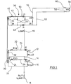
- FIG. 1 shows two lithium-ion cells 10, 12, which are shown in their equivalent circuit diagram respectively as voltage sources V1 and V2 and their internal resistances Ri_Li1 and Ri_Li2. In order to better explain the operation of the balancing unit, it is assumed below that V2 is greater than V1.
- the lithium-ion cells 10 and 12 are electrically connected to each other via a line 14 and thus generate at the terminals 16 and 18, the battery voltage U BAT .
- Each of the lithium cells 10 and 12 is connected to a circuit 20, 22.
- the circuit 22 of the lithium cell 10 will be described in more detail.
- the circuit has a coil 24, which serves as an inductive storage of the circuit.
- the circuit 22 has a switching element 26, which is shown in the closed state.
- another coil 28 and a switching resistor RV1 are provided in the circuit 22.
- the serving as inductive storage coil 24 is inductively coupled to an iron core 30, which serves as a transmitter.
- the circuit of the lithium cell 12 is constructed accordingly, wherein serving as an inductive storage coil 32 is also inductively coupled to the transmitter 30.
- the circuit 20 is switched via the switching element 34.
- the switches 26 and 34 are opened and closed synchronously.
- the pulse widths for the control of the switching elements 26 and 34 are determined by a non-predetermined control unit.
- the switches 26 and 34 are closed.
- the switches 26 and 34 are opened.
- an additional demagnetization winding (not shown) may be provided in the circuits 20 and 22 to receive the magnetizing current. Otherwise, the demagnetization can also take place via the demagnetization unit 36 described below.
- the demagnetization unit 36 has a coil 38, which is inductively coupled to the transmitter 30 and serves as an inductive load memory.
- the degaussing unit 36 has an additional coil 40 and an ohmic resistor 42.
- Two diodes 44 and 46 together with the switches 48 and 50 form a bridge circuit.
- the switches 48 and 50 are preferably designed as transistors again.
- the transistor bridge is connected via lines 52 and 54 to a mains voltage 56, wherein for the separation of the mains voltage switches 58, 60 are provided.
- An intermediate circuit capacitor C5 is provided in a DC link of the demagnetization unit.
- a current flows into the coil 38 when the switches 48 and 50 are closed and the demagnetization unit is connected to the mains voltage 56 via the switches 58 and 60. If the switches 48 and 50 are opened, a demagnetizing current flows via the coil 38 into the DC link capacitor C5.
- the degaussing unit 36 is driven with its transistors 48 and 50 in synchronism with the transistors 26 and 34 of the circuits 20 and 22. In this case, when the switches 58 and 60 are closed, a charging operation takes place via the demagnetization unit 36. When the switches 58 and 60 are opened, there is a balance between the lithium cells 10 and 12.
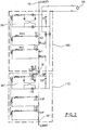
- Fig. 2 shows two balancing units 100 and 110, wherein for clarity the same reference numerals as in Fig. 1 be used for the components.
- the demagnetizing units 36 and 36 "of the balancing units 100 and 110 respectively connected in parallel to the external mains voltage 56.
- the terminals of the balancing units 100 and 110 are in the in Fig. 2
- the connection of the balance unit 100 to the terminal 16 "of the balancing unit 110 is connected to the port 18 of the balance unit 100.
- the total voltage is tapped off at the terminals 16 and 18".
- the balancing units 100 and 110 and optionally further balancing units such as batteries can be combined with one another in any form.
- With a series connection of the balancing units the total voltage increases, while in a parallel connection increases the charge of the voltage sources in the balancing units.
- the charge equalization is carried out by the higher charged Balancierritt to the lower charged Balancierritt, while the voltage sources V1, V2 and V1 "and V2" within the balancing units continue to be balanced.
Landscapes
- Engineering & Computer Science (AREA)
- Power Engineering (AREA)
- Charge And Discharge Circuits For Batteries Or The Like (AREA)
Abstract
Description
- Die vorliegende Erfindung betrifft eine Vorrichtung zum aktiven Balancieren von in Reihe geschalteten Spannungsquellen, insbesondere von Lithium-Ionen-Zellen und von Kondensatoren.
- Auf
DE 10 2008 021 090 A1 ist eine Schaltungsanordnung zum Austausch elektrischer Ladung zwischen Akkumulatoren einer Akkumulatoranordnung bekannt. Die bekannte Schaltungsanordnung besitzt eine Anzahl von ersten Reihenschaltungen zum Parallelschalten mit jeweils einem Akkumulator, die jeweils ein Schaltelement mit einer Laststrecke und einem Ansteueranschluss sowie ein in Reihe zu der Laststrecke geschaltetes induktives Speicherelement aufweist. Ferner besitzt die bekannte Schaltungsanordnung eine weitere Reihenschaltung zum Parallelschalten mit der Akkumulatoranordnung, die ein Schaltelement mit einer Laststrecke und einem Ansteueranschluss und ein in Reihe zu der Lastrecke des Schaltelements geschaltetes induktives Speicherelement aufweist, wobei das induktive Speicherelement der weiteren Reihenschaltung induktiv mit den induktiven Speicherelementen der ersten Reihenschaltung gekoppelt ist. Eine Ansteuerschaltung ist mit den Steueranschlüssen gekoppelt und ermittelt anhand von gemessenen Akkumulatorspannungen welchem Akkumulator elektrische Energie entnommen und welchem Akkumulator die entnommene Energie zugeführt werden soll. - Aus
US 2010/0090649 A1 ist eine Schaltungsanordnung von in Reihe geschalteten Akkumulatoren bekannt geworden, die über einen aktiven Balancierschaltkreis untereinander balanciert werden. Hierbei arbeitet der Balancierschaltkreis als Sperrwandler, bei dem ein gemeinsamer Eisenkern magnetisiert wird und die bereitgestellten Magnetisierungskerne durch die einzelnen Schaltkreise entsprechend ihrem Ladezustand entnommen werden. - Die bekannten Balanciereinheiten erfordern stets eine einzelne Ansteuerung der Schaltelemente in den Schaltkreisen für die in Reihe geschalteten Spannungsquellen, wodurch ein großer steuerungstechnischer Aufwand entsteht.
- Der Erfindung liegt die Aufgabe zugrunde, eine Vorrichtung zum aktiven Balancieren von in Reihe geschalteten Spannungsquellen bereitzustellen, bei der durch einen geringen schalt- und messtechnischen Aufwand eine zuverlässige Balancierung der Spannungsquellen erfolgen kann.
- Erfindungsgemäß wird die Aufgabe durch eine Vorrichtung mit den Merkmalen aus Anspruch 1 gelöst. Vorteilhafte Ausgestaltungen bilden den Gegenstand der Unteransprüche.
- Die erfindungsgemäße Vorrichtung ist vorgesehen und bestimmt zur aktiven Balancierung von in Reihe geschalteten Spannungsquellen, wie beispielsweise in Reihe geschalteten Lithium-Ionen-Zellen oder andere Batterien oder in Reihe geschalteten Kondensatoren. Die Vorrichtung ist gekennzeichnet durch einen Schaltkreis für jede Spannungsquelle, der mit der Spannungsquelle verbunden ist und ein Schaltelement sowie einen induktiven Speicher aufweist. Ferner besitzt die erfindungsgemäße Vorrichtung einen Überträger, der mit jedem induktiven Speicher induktiv gekoppelt ist. Erfindungsgemäß werden die Schaltkreise derart synchron geschaltet, dass elektrische Energie in geschaltetem Zustand aus dem Schaltkreis mit der Spannungsquelle, die die höchste Spannung besitzt, über den induktiven Speicher und den Überträger auf einen oder mehrere Schaltkreise der anderen Spannungsquellen übertragen wird. Ein besonderer Vorteil der erfindungsgemäßen Vorrichtung liegt darin, dass die Schaltkreise der Spannungsquelle synchron geschaltet werden und aufgrund der induktiven Kopplung der Schaltkreise an dem
- Überträger elektrische Energie zwischen den Schaltkreisen übertragen wird. Bei der Übertragung der elektrischen Energie zwischen den Schaltkreisen wirkt der induktive Speicher als Primärspeicher, über den elektrische Energie in den Überträger eingetragen wird und der oder die übrigen induktiven Speicher der anderen Schaltkreise als Sekundärspeicher die elektrische Energie aus dem Überträger entnehmen. Indem die Magnetisierung der induktiven Speicher in den einzelnen Schaltkreisen abhängig von der Spannung der zugehörigen Spannungsquelle ist, stellt die erfindungsgemäße Vorrichtung sicher, dass eine Spannungsquelle mit einer hohen Spannung elektrische Energie abgibt und eine oder mehrere Spannungsquellen mit einer niedrigen Spannung zwar ebenfalls ihre induktiven Speicher magnetisieren, jedoch mehr elektrische Energie aufnehmen, um die Spannung der Spannungsquelle zu erhöhen.
- In einer bevorzugten Ausgestaltung sind die induktiven Speicher jeweils als eine Spule ausgebildet. Als Schaltelement in den Schaltkreisen ist bevorzugt jeweils ein Transistor vorgesehen. Bevorzugt sind die Schaltkreise der einzelnen Spannungsquellen als Synchrongleichrichter ausgebildet, wobei im geschalteten und im nicht geschalteten Zustand der Strom in die gleiche Richtung fließt.
- In einer bevorzugten Ausgestaltung wird der induktive Speicher in dem Schaltkreis entsprechend der Spannung in der Spannungsquelle magnetisiert, wenn das Schaltelement im Schaltkreis geschlossen ist. Wenn das Schaltelement in dem Schaltkreis geöffnet ist, wird entsprechend der Magnetisierung des Überträgers und des induktiven Speichers ein Balancierstrom zu der Spannungsquelle erzeugt. Der Schaltkreis der Spannungsquelle arbeitet somit nach dem Prinzip eines Eintaktdurchflusswandlers, bei dem die Energieübertragung in den Schaltkreis ausschließlich in der Leitphase des Schaltelements erfolgt.
- In einer bevorzugten Ausgestaltung ist der Überträger als ein gemeinsamer Spulenkern für die Schaltkreise der Spannungsquellen ausgebildet.
- In einer besonders bevorzugten Weiterbildung der Erfindung ist eine Entmagnetisierungseinheit vorgesehen, über die die Spannungsquellen der einzelnen Schaltkreise geladen werden können. Hierdurch können die einzelnen Spannungsquellen auch während eines Ladevorgangs untereinander balanciert werden.
- In der bevorzugten Weiterbildung ist eine Entmagnetisierungseinheit vorgesehen, die mit einer Netzspannung verbindbar ist und die einen mit dem Überträger induktiv gekoppelten induktiven Ladespeicher mit jeweils mindestens einem Schaltelement aufweist. Der induktive Ladespeicher wird unabhängig davon, ob die Entmagnetisierungseinheit mit der Netzspannung verbunden ist oder nicht synchron mit den Schaltkreisen der Spannungsquelle geschaltet, um magnetisiert oder entmagnetisiert zu werden.
- Ist die Entmagnetisierungseinheit mit der Netzspannung verbunden, wird über den induktiven Ladespeicher als Primärspeicher elektrische Energie an die induktiven Speicher der Schaltkreise transportiert, um die Spannungsquellen zu laden. Auch während dieses Ladevorgangs werden die einzelnen Spannungsquellen untereinander balanciert, da die von den Schaltkreisen der Spannungsquelle aufgenommene elektrische Energie umso größer ist, je kleiner die Spannung der Spannungsquelle ist. In dem Betrieb der Entmagnetisierungseinheit, in dem diese mit der Netzspannung verbunden ist, erfolgt ein Laden der Spannungsquellen.
- In einer weiteren bevorzugten Ausgestaltung ist die Entmagnetisierungseinheit mit einem Kondensator ausgestattet, der, wenn die Entmagnetisierungseinheit von der Netzspannung getrennt ist, einen Entmagnetisierungsstrom des induktiven Ladespeichers in einer Ausschaltphase der Steuerelemente aufnimmt und in der Einschaltphase die elektrische Energie zurück in den induktiven Ladespeicher speist. Auf diese Weise bleibt die Entmagnetisierungseinheit, auch sie wenn nicht über die Netzspannung die einzelnen Spannungsquellen lädt, induktiv mit der Balanciereinheit gekoppelt.
- Eine bevorzugte Ausgestaltung der Erfindung wird nachfolgend anhand der Figuren näher erläutert. Es zeigt:
- Fig. 1
- einen Schaltplan für eine Balanciereinheit und
- Fig. 2
- einen Schaltplan mit zwei kaskadierten Balanciereinheiten.
-
Figur 1 zeigt zwei Lithium-Ionen-Zellen 10, 12, die in ihrem Ersatzschaltbild jeweils als Spannungsquellen V1 und V2 sowie ihren Innenwiderständen Ri_Li1 und Ri_Li2 dargestellt sind. Um die Arbeitsweise der Balanciereinheit besser erklären zu können, sei nachfolgend angenommen, dass V2 größer als V1 ist. - Die Lithium-Ionen-Zellen 10 und 12 sind über eine Leitung 14 elektrisch miteinander verbunden und erzeugen so an den Klemmen 16 und 18 die Batteriespannung UBAT. Jede der Lithium-Zellen 10 und 12 ist mit einem Schaltkreis 20, 22 verbunden. Nachfolgend wird der Schaltkreis 22 der Lithium-Zelle 10 näher beschrieben. Der Schaltkreis besitzt eine Spule 24, die als induktiver Speicher des Schaltkreises dient. Ferner besitzt der Schaltkreis 22 ein Schaltelement 26, das im geschlossenen Zustand dargestellt ist. Ferner ist eine weitere Spule 28 sowie ein Schaltwiderstand RV1 in dem Schaltkreis 22 vorgesehen.
- Die als induktiver Speicher dienende Spule 24 ist induktiv mit einem Eisenkern 30 gekoppelt, der als Überträger dient.
- Der Schaltkreis der Lithium-Zelle 12 ist entsprechend aufgebaut, wobei die als induktiver Speicher dienende Spule 32 ebenfalls induktiv mit dem Überträger 30 gekoppelt ist. Der Schaltkreis 20 wird über das Schaltelement 34 geschaltet.
- Für ein erstes Verständnis der Balanciereinheit genügt es, den vorstehend beschriebenen Teil des Schaltplans zu betrachten. Dass der Überträger 30 noch mit einem Netzteil 36 induktiv gekoppelt ist, kann zunächst unberücksichtigt bleiben.
- Im Betrieb werden die Schalter 26 und 34 synchron geöffnet und geschlossen. Die Pulsweiten für die Ansteuerung der Schaltelemente 26 und 34 werden von einer nicht vorgegebenen Steuereinheit bestimmt. Im Leitzustand sind die Schalter 26 und 34 geschlossen.
- Wenn der Schalter 26 geschlossen ist, fließt ein Strom durch die Spule 24 über den Überträger 30 in die Spule 32 des Schaltkreises 20. Ebenso fließt ein Strom, jedoch in entgegengesetzter Richtung von der zweiten Lithium-Zelle 12 über die Spule 32 in die Spule 24. Die entgegengesetzt gerichteten Ströme bilden insgesamt einen resultierenden Strom, wobei aufgrund der getroffenen Annahme, dass die Spannung V2 größer als V1 ist, in Schaltkreis 20 der Strom 12 fließt und in Schaltkreis 22 der Strom I1 fließt. Dabei ist der Strom I1 ein Ladestrom für die Lithium-Zelle 10, während der Strom I2 eine Entladung für die Lithium-Zelle 12 bewirkt.
- Im Sperrzustand sind die Schalter 26 und 34 geöffnet. Hier kann in den Schaltkreisen 20 und 22 eine zusätzliche Entmagnetisierungswicklung (ni cht dargestellt) vorgesehen sein, um den Magnetisierungsstrom aufzunehmen. Ansonsten kann die Entmagnetisierung auch über die nachfolgend beschriebene Entmagnetisierungseinheit 36 erfolgen.
- Die Entmagnetisierungseinheit 36 weist eine Spule 38 auf, die induktiv mit dem Überträger 30 gekoppelt ist und als induktiver Ladespeicher dient. Die Entmagnetisierungseinheit 36 besitzt eine zusätzliche Spule 40 und einen ohmschen Widerstand 42. Zwei Dioden 44 und 46 bilden zusammen mit den Schaltern 48 und 50 eine Brückenschaltung. Die Schalter 48 und 50 sind bevorzugt wieder als Transistoren ausgeführt. Die Transistorbrücke ist über Leitungen 52 und 54 mit einer Netzspannung 56 verbunden, wobei zur Trennung der Netzspannung Schalter 58, 60 vorgesehen sind. In einem Zwischenkreis der Entmagnetisierungseinheit ist ein Zwischenkreiskondensator C5 vorgesehen.
- In der Entmagnetisierungseinheit 36 fließt ein Strom in die Spule 38, wenn die Schalter 48 und 50 geschlossen sind und die Entmagnetisierungseinheit über die Schalter 58 und 60 mit der Netzspannung 56 verbunden ist. Werden die Schalter 48 und 50 geöffnet, fließt ein Entmagnetisierungsstrom über die Spule 38 in den Zwischenkreiskondensator C5.
- Die Entmagnetisierungseinheit 36 wird mit seinen Transistoren 48 und 50 synchron zu den Transistoren 26 und 34 der Schaltkreise 20 und 22 angesteuert. Hierbei ist es so, dass, wenn die Schalter 58 und 60 geschlossen sind, ein Ladebetrieb über die Entmagnetisierungseinheit 36 erfolgt. Sind die Schalter 58 und 60 geöffnet, erfolgt eine Balancierung zwischen den Lithium-Zellen 10 und 12.
-
Fig. 2 zeigt zwei Balanciereinheiten 100 und 110, wobei zur besseren Übersicht die gleichen Bezugszeichen wie inFig. 1 für die Komponenten verwendet werden. Die Entmagnetisierungseinheiten 36 und 36" der Balanciereinheiten 100 bzw. 110 sind parallel zueinander an die externe Netzspannung 56 geschaltet. Die Anschlüsse der Balanciereinheiten 100 und 110 sind bei der inFig. 2 dargestellten Kaskadierung seriell geschaltet, so dass der Anschluss 18 der Balanciereinheit 100 mit dem Anschluss 16" der Balanciereinheit 110 verbunden ist. Die Gesamtspannung wird an den Anschlüssen 16 und 18" abgegriffen. Grundsätzlich ist es so, dass die Balanciereinheiten 100 und 110 und gegebenenfalls weitere Balanciereinheiten wie Batterien in jeder Form miteinander kombinierbar sind. Bei einer Reihenschaltung der Balanciereinheiten erhöht sich die Gesamtspannung, während sich bei einer Parallelschaltung die Ladung der Spannungsquellen in den Balanciereinheiten erhöht. - Durch die Parallelschaltung der Balanciereinheiten 100 und 110 mit der Spannungsversorgung 56 erfolgt, auch wenn keine Netzspannung anliegt, ein Ladungsausgleich zwischen den Balanciereinheiten 100 und 110. Der Ladungsausgleich erfolgt von der höher geladenen Balanciereinheit zu der geringer geladenen Balanciereinheit, während gleichzeitig die Spannungsquellen V1, V2 und V1" und V2" innerhalb der Balanciereinheiten weiterhin balanciert werden.
Claims (11)
- Vorrichtung zur aktiven Balancierung von in Reihe geschalteten Spannungsquellen (10, 12), insbesondere von Lithium-Ionen-Zellen und von Kondensatoren, gekennzeichnet durch- einen Schaltkreis (20, 22) für jede Spannungsquelle (10, 12), der mit der Spannungsquelle (10,12) verbunden ist und ein Schaltelement (26, 34) sowie einen induktiven Speicher (24, 32) aufweist,- einen Überträger (30), der mit dem induktiven Speicher (24, 32) induktiv gekoppelt ist,- wobei die Schaltkreise (20, 22) synchron geschaltet werden derart, dass elektrische Energie aus dem Schaltkreis (20) mit der Spannungsquelle (12), die eine höchste Spannung (V2) besitzt, über den induktiven Speicher (32) und den Überträger (30) auf die Schaltkreise (22) einer oder mehrerer anderer Spannungsquellen (10) übertragen wird
- Vorrichtung nach Anspruch 1, dadurch gekennzeichnet, dass der induktive Speicher (24, 32, 38) als Spule ausgebildet ist.
- Vorrichtung nach Anspruch 1 oder 2, dadurch gekennzeichnet, dass der Schaltkreis (20, 22) einen Transistor (26, 34) als Schaltelement aufweist.
- Vorrichtung nach einem der Ansprüche 1 bis 3, dadurch gekennzeichnet, dass in dem Schaltkreis (20, 22) der Strom im leitenden und nicht leitenden Zustand des Schaltelements in die gleiche Richtung fließt.
- Vorrichtung nach einem der Ansprüche 1 bis 4, dadurch gekennzeichnet, dass, wenn der Schaltkreis (20, 22) geschlossen wird, der induktive Speicher (24, 32) entsprechend der Spannung (V1, V2) der Spannungsquelle (10, 12) magnetisiert wird und, wenn das Schaltelement (26, 34) geöffnet wird, entsprechend der Magnetisierung des Überträgers (30) und des induktiven Speichers (24, 32) einen Balancierstrom (I1) für die Spannungsquelle erzeugt wird.
- Vorrichtung nach einem der Ansprüche 1 bis 5, dadurch gekennzeichnet, dass der Überträger (30) als ein gemeinsamer Spulenkern für die Schaltkreise der Spannungsquellen ausgebildet ist.
- Vorrichtung nach einem der Ansprüche 1 bis 6, dadurch gekennzeichnet, dass eine Entmagnetisierungseinheit (36) vorgesehen ist, die mit einer Netzspannung verbindbar ist und die einen mit dem Überträger induktiv gekoppelten induktiven Ladespeicher (38) sowie mindestens ein Schaltelement (40, 50) aufweist.
- Vorrichtung nach Anspruch 7, dadurch gekennzeichnet, dass der induktive Ladespeicher (38) synchron mit den Schaltkreisen (20, 22) der Spannungsquellen (10, 12) geschaltet wird, um magnetisiert oder entmagnetisiert zu werden.
- Vorrichtung nach Anspruch 7 oder 8, dadurch gekennzeichnet, dass, wenn die Entmagnetisierungseinheit (36) mit der Netzspannung (56) verbunden ist, über den induktiven Ladespeicher (38) als Primärspeicher elektrische Energie an die induktiven Speicher der Schaltkreise transportiert wird, um die Spannungsquellen (10, 12) zu laden.
- Vorrichtung nach einem der Ansprüche 7 bis 9, dadurch gekennzeichnet, dass die Entmagnetisierungseinheit (36) einen Kondensator (C5) aufweist, der, wenn die Entmagnetisierungseinheit von der Netzspannung (56) getrennt ist, einen Entmagnetisierungsstrom des induktiven Ladespeichers (38) in einer Ausschaltphase der Entmagnetisierungseinheit (36) aufnimmt und in der Einschaltphase die elektrische Energie zurück in den induktiven Ladespeicher (38) speist.
- Vorrichtung nach Anspruch 10, dadurch gekennzeichnet, dass die Einschalt-und Anschaltphase der Entmagnetisierungseinheit mit den Schaltkreisen (20, 22) gleich getaktet ist.
Applications Claiming Priority (1)
| Application Number | Priority Date | Filing Date | Title |
|---|---|---|---|
| DE102011014925A DE102011014925A1 (de) | 2011-03-24 | 2011-03-24 | Vorrichtung zum aktiven Balancieren von Spannungsquellen |
Publications (2)
| Publication Number | Publication Date |
|---|---|
| EP2503661A1 true EP2503661A1 (de) | 2012-09-26 |
| EP2503661B1 EP2503661B1 (de) | 2017-10-18 |
Family
ID=45654769
Family Applications (1)
| Application Number | Title | Priority Date | Filing Date |
|---|---|---|---|
| EP12000456.9A Active EP2503661B1 (de) | 2011-03-24 | 2012-01-26 | Vorrichtung zum aktiven Balancieren von Spannungsquellen |
Country Status (2)
| Country | Link |
|---|---|
| EP (1) | EP2503661B1 (de) |
| DE (1) | DE102011014925A1 (de) |
Families Citing this family (1)
| Publication number | Priority date | Publication date | Assignee | Title |
|---|---|---|---|---|
| CN112265473B (zh) * | 2020-10-19 | 2021-11-30 | 珠海格力电器股份有限公司 | 一种驱动装置 |
Citations (4)
| Publication number | Priority date | Publication date | Assignee | Title |
|---|---|---|---|---|
| DE10151656A1 (de) * | 2000-10-19 | 2002-07-11 | Fuji Jukogyo Kk Tokio | Spannungsausgleichsvorrichtung und -Verfahren |
| US20050077879A1 (en) * | 2003-10-14 | 2005-04-14 | Near Timothy Paul | Energy transfer device for series connected energy source and storage devices |
| DE102008021090A1 (de) | 2007-05-01 | 2008-11-13 | Infineon Technologies Ag | Schaltungsanordnung und Verfahren zum Austausch elektrischer Ladung zwischen Akkumulatoren einer Akkumulatoranordnung |
| US20100090649A1 (en) | 2007-04-18 | 2010-04-15 | Pierre Sardat | Engine storage device, particularly for an automobile |
Family Cites Families (5)
| Publication number | Priority date | Publication date | Assignee | Title |
|---|---|---|---|---|
| DE4428769C1 (de) * | 1994-08-13 | 1996-05-02 | Fraunhofer Ges Forschung | Vorrichtung zur Aufladung von und/oder zum Ladungsaustausch zwischen einer Vielzahl von in Reihe geschalteten Energiespeichern |
| DE19510835C1 (de) * | 1995-03-24 | 1996-10-17 | Jungheinrich Ag | Verfahren zum Testen einer Antriebs-Schaltungsanordnung für ein Flurförderzeug |
| EP1609661A1 (de) * | 2004-06-24 | 2005-12-28 | Nederlandse Organisatie voor toegepast-natuurwetenschappelijk Onderzoek TNO | Gleichspannungsversorgungssystem |
| DE102004054167A1 (de) * | 2004-11-10 | 2006-05-11 | Jungheinrich Aktiengesellschaft | Ladegerät für ein Flurförderzeug |
| DE102006009312A1 (de) * | 2006-03-01 | 2007-09-06 | Jungheinrich Aktiengesellschaft | Flurförderzeug mit einem Ladegerät |
-
2011
- 2011-03-24 DE DE102011014925A patent/DE102011014925A1/de not_active Withdrawn
-
2012
- 2012-01-26 EP EP12000456.9A patent/EP2503661B1/de active Active
Patent Citations (4)
| Publication number | Priority date | Publication date | Assignee | Title |
|---|---|---|---|---|
| DE10151656A1 (de) * | 2000-10-19 | 2002-07-11 | Fuji Jukogyo Kk Tokio | Spannungsausgleichsvorrichtung und -Verfahren |
| US20050077879A1 (en) * | 2003-10-14 | 2005-04-14 | Near Timothy Paul | Energy transfer device for series connected energy source and storage devices |
| US20100090649A1 (en) | 2007-04-18 | 2010-04-15 | Pierre Sardat | Engine storage device, particularly for an automobile |
| DE102008021090A1 (de) | 2007-05-01 | 2008-11-13 | Infineon Technologies Ag | Schaltungsanordnung und Verfahren zum Austausch elektrischer Ladung zwischen Akkumulatoren einer Akkumulatoranordnung |
Also Published As
| Publication number | Publication date |
|---|---|
| EP2503661B1 (de) | 2017-10-18 |
| DE102011014925A1 (de) | 2012-09-27 |
Similar Documents
| Publication | Publication Date | Title |
|---|---|---|
| DE102008021090B4 (de) | Schaltungsanordnung und Verfahren zum Austausch elektrischer Ladung zwischen Akkumulatoren einer Akkumulatoranordnung | |
| DE102008044404B4 (de) | Schaltung zum Ausgleich von Ladungsunsymmetrien in Speicherzellen | |
| EP2408086B1 (de) | Energiespeicheranordnung | |
| DE102017207102A1 (de) | Stationärspeicher zum Zwischenspeichern von elektrischer Energie in einem elektrischen Versorgungsnetz sowie Betriebsverfahren und Nachrüstmodul für den Stationärspeicher | |
| DE102013019759A1 (de) | Ausgleichssteuerschaltung für ein Batteriezellenmodul unter Verwendung einer LC-Reihenresonanzschaltung | |
| EP4022758B1 (de) | Ansteuerverfahren für einen gleichspannungswandler und gleichspannungswandler | |
| DE102009000055A1 (de) | Batteriezellen-Balancing | |
| DE102015117744A1 (de) | Batteriesystem | |
| WO2011098206A2 (de) | Schaltungsanordnung | |
| DE112010005440B4 (de) | Ansteuerschaltung für elektromagnetischen Betätigungsmechanismus | |
| DE112018004442T5 (de) | Energiespeicherapparatur | |
| DE102010016852A1 (de) | Energieversorgungssystem für Kraftfahrzeuge | |
| DE102015007264A1 (de) | Schnelles Übertragen von elektrischer Energie von einer Ladestation zu einem Verbraucher | |
| EP2503661B1 (de) | Vorrichtung zum aktiven Balancieren von Spannungsquellen | |
| EP3084918B1 (de) | Elektrische energiespeichervorrichtung mit symmetrierschaltung | |
| EP2502777B1 (de) | Flurförderzeug mit einem elektrischen Antrieb | |
| DE102019207968B4 (de) | Vorrichtung zur induktiven Übertragung elektrischer Energie | |
| WO2013107556A1 (de) | Schaltungsanordnung zur reduktion der stromstärke in einer hochspannungs-gleichstrom-übertragungsleitung, hochspannungs-gleichstrom-übertragungsanlage und verfahren zum reduzieren der stromstärke eines elektrischen stromes | |
| DE112016000602B4 (de) | Energieversorgungseinrichtung | |
| EP3710304A1 (de) | Kraftfahrzeug mit einem energiespeicher sowie verfahren zum betreiben eines kraftfahrzeugs | |
| DE102012201844A1 (de) | Vorladung einer Kapazität eines elektrischen Verbrauchers aus einem galvanisch getrennten elektrischen Energiespeicher | |
| DE102007022286A1 (de) | Medizinisches System mit galvanischer Trennung | |
| EP3583688B1 (de) | Schaltvorrichtung und deren verwendung zur vorladung | |
| DE112016001556T5 (de) | Spannungsausgleichs-Korrekturschaltung | |
| EP2548281A2 (de) | Verfahren zum ladungsausgleich in einem batteriesystem und batteriesystem mit einer ladungsausgleichsschaltung |
Legal Events
| Date | Code | Title | Description |
|---|---|---|---|
| PUAI | Public reference made under article 153(3) epc to a published international application that has entered the european phase |
Free format text: ORIGINAL CODE: 0009012 |
|
| AK | Designated contracting states |
Kind code of ref document: A1 Designated state(s): AL AT BE BG CH CY CZ DE DK EE ES FI FR GB GR HR HU IE IS IT LI LT LU LV MC MK MT NL NO PL PT RO RS SE SI SK SM TR |
|
| AX | Request for extension of the european patent |
Extension state: BA ME |
|
| 17P | Request for examination filed |
Effective date: 20121103 |
|
| 17Q | First examination report despatched |
Effective date: 20141013 |
|
| GRAP | Despatch of communication of intention to grant a patent |
Free format text: ORIGINAL CODE: EPIDOSNIGR1 |
|
| STAA | Information on the status of an ep patent application or granted ep patent |
Free format text: STATUS: GRANT OF PATENT IS INTENDED |
|
| INTG | Intention to grant announced |
Effective date: 20170512 |
|
| GRAS | Grant fee paid |
Free format text: ORIGINAL CODE: EPIDOSNIGR3 |
|
| GRAA | (expected) grant |
Free format text: ORIGINAL CODE: 0009210 |
|
| STAA | Information on the status of an ep patent application or granted ep patent |
Free format text: STATUS: THE PATENT HAS BEEN GRANTED |
|
| AK | Designated contracting states |
Kind code of ref document: B1 Designated state(s): AL AT BE BG CH CY CZ DE DK EE ES FI FR GB GR HR HU IE IS IT LI LT LU LV MC MK MT NL NO PL PT RO RS SE SI SK SM TR |
|
| RAP1 | Party data changed (applicant data changed or rights of an application transferred) |
Owner name: JUNGHEINRICH AKTIENGESELLSCHAFT |
|
| REG | Reference to a national code |
Ref country code: GB Ref legal event code: FG4D Free format text: NOT ENGLISH |
|
| REG | Reference to a national code |
Ref country code: CH Ref legal event code: EP |
|
| REG | Reference to a national code |
Ref country code: AT Ref legal event code: REF Ref document number: 938736 Country of ref document: AT Kind code of ref document: T Effective date: 20171115 Ref country code: IE Ref legal event code: FG4D Free format text: LANGUAGE OF EP DOCUMENT: GERMAN |
|
| REG | Reference to a national code |
Ref country code: DE Ref legal event code: R096 Ref document number: 502012011455 Country of ref document: DE |
|
| REG | Reference to a national code |
Ref country code: FR Ref legal event code: PLFP Year of fee payment: 7 |
|
| REG | Reference to a national code |
Ref country code: SE Ref legal event code: TRGR |
|
| REG | Reference to a national code |
Ref country code: NL Ref legal event code: MP Effective date: 20171018 |
|
| REG | Reference to a national code |
Ref country code: LT Ref legal event code: MG4D |
|
| PG25 | Lapsed in a contracting state [announced via postgrant information from national office to epo] |
Ref country code: NL Free format text: LAPSE BECAUSE OF FAILURE TO SUBMIT A TRANSLATION OF THE DESCRIPTION OR TO PAY THE FEE WITHIN THE PRESCRIBED TIME-LIMIT Effective date: 20171018 |
|
| PG25 | Lapsed in a contracting state [announced via postgrant information from national office to epo] |
Ref country code: LT Free format text: LAPSE BECAUSE OF FAILURE TO SUBMIT A TRANSLATION OF THE DESCRIPTION OR TO PAY THE FEE WITHIN THE PRESCRIBED TIME-LIMIT Effective date: 20171018 Ref country code: ES Free format text: LAPSE BECAUSE OF FAILURE TO SUBMIT A TRANSLATION OF THE DESCRIPTION OR TO PAY THE FEE WITHIN THE PRESCRIBED TIME-LIMIT Effective date: 20171018 Ref country code: NO Free format text: LAPSE BECAUSE OF FAILURE TO SUBMIT A TRANSLATION OF THE DESCRIPTION OR TO PAY THE FEE WITHIN THE PRESCRIBED TIME-LIMIT Effective date: 20180118 Ref country code: FI Free format text: LAPSE BECAUSE OF FAILURE TO SUBMIT A TRANSLATION OF THE DESCRIPTION OR TO PAY THE FEE WITHIN THE PRESCRIBED TIME-LIMIT Effective date: 20171018 |
|
| PG25 | Lapsed in a contracting state [announced via postgrant information from national office to epo] |
Ref country code: RS Free format text: LAPSE BECAUSE OF FAILURE TO SUBMIT A TRANSLATION OF THE DESCRIPTION OR TO PAY THE FEE WITHIN THE PRESCRIBED TIME-LIMIT Effective date: 20171018 Ref country code: BG Free format text: LAPSE BECAUSE OF FAILURE TO SUBMIT A TRANSLATION OF THE DESCRIPTION OR TO PAY THE FEE WITHIN THE PRESCRIBED TIME-LIMIT Effective date: 20180118 Ref country code: LV Free format text: LAPSE BECAUSE OF FAILURE TO SUBMIT A TRANSLATION OF THE DESCRIPTION OR TO PAY THE FEE WITHIN THE PRESCRIBED TIME-LIMIT Effective date: 20171018 Ref country code: HR Free format text: LAPSE BECAUSE OF FAILURE TO SUBMIT A TRANSLATION OF THE DESCRIPTION OR TO PAY THE FEE WITHIN THE PRESCRIBED TIME-LIMIT Effective date: 20171018 Ref country code: GR Free format text: LAPSE BECAUSE OF FAILURE TO SUBMIT A TRANSLATION OF THE DESCRIPTION OR TO PAY THE FEE WITHIN THE PRESCRIBED TIME-LIMIT Effective date: 20180119 Ref country code: IS Free format text: LAPSE BECAUSE OF FAILURE TO SUBMIT A TRANSLATION OF THE DESCRIPTION OR TO PAY THE FEE WITHIN THE PRESCRIBED TIME-LIMIT Effective date: 20180218 |
|
| REG | Reference to a national code |
Ref country code: DE Ref legal event code: R097 Ref document number: 502012011455 Country of ref document: DE |
|
| PG25 | Lapsed in a contracting state [announced via postgrant information from national office to epo] |
Ref country code: CZ Free format text: LAPSE BECAUSE OF FAILURE TO SUBMIT A TRANSLATION OF THE DESCRIPTION OR TO PAY THE FEE WITHIN THE PRESCRIBED TIME-LIMIT Effective date: 20171018 Ref country code: EE Free format text: LAPSE BECAUSE OF FAILURE TO SUBMIT A TRANSLATION OF THE DESCRIPTION OR TO PAY THE FEE WITHIN THE PRESCRIBED TIME-LIMIT Effective date: 20171018 Ref country code: SK Free format text: LAPSE BECAUSE OF FAILURE TO SUBMIT A TRANSLATION OF THE DESCRIPTION OR TO PAY THE FEE WITHIN THE PRESCRIBED TIME-LIMIT Effective date: 20171018 Ref country code: DK Free format text: LAPSE BECAUSE OF FAILURE TO SUBMIT A TRANSLATION OF THE DESCRIPTION OR TO PAY THE FEE WITHIN THE PRESCRIBED TIME-LIMIT Effective date: 20171018 |
|
| PLBE | No opposition filed within time limit |
Free format text: ORIGINAL CODE: 0009261 |
|
| STAA | Information on the status of an ep patent application or granted ep patent |
Free format text: STATUS: NO OPPOSITION FILED WITHIN TIME LIMIT |
|
| PG25 | Lapsed in a contracting state [announced via postgrant information from national office to epo] |
Ref country code: RO Free format text: LAPSE BECAUSE OF FAILURE TO SUBMIT A TRANSLATION OF THE DESCRIPTION OR TO PAY THE FEE WITHIN THE PRESCRIBED TIME-LIMIT Effective date: 20171018 Ref country code: PL Free format text: LAPSE BECAUSE OF FAILURE TO SUBMIT A TRANSLATION OF THE DESCRIPTION OR TO PAY THE FEE WITHIN THE PRESCRIBED TIME-LIMIT Effective date: 20171018 Ref country code: SM Free format text: LAPSE BECAUSE OF FAILURE TO SUBMIT A TRANSLATION OF THE DESCRIPTION OR TO PAY THE FEE WITHIN THE PRESCRIBED TIME-LIMIT Effective date: 20171018 |
|
| REG | Reference to a national code |
Ref country code: CH Ref legal event code: PL |
|
| 26N | No opposition filed |
Effective date: 20180719 |
|
| PG25 | Lapsed in a contracting state [announced via postgrant information from national office to epo] |
Ref country code: MT Free format text: LAPSE BECAUSE OF FAILURE TO SUBMIT A TRANSLATION OF THE DESCRIPTION OR TO PAY THE FEE WITHIN THE PRESCRIBED TIME-LIMIT Effective date: 20171018 |
|
| PG25 | Lapsed in a contracting state [announced via postgrant information from national office to epo] |
Ref country code: LU Free format text: LAPSE BECAUSE OF NON-PAYMENT OF DUE FEES Effective date: 20180126 |
|
| REG | Reference to a national code |
Ref country code: IE Ref legal event code: MM4A |
|
| REG | Reference to a national code |
Ref country code: BE Ref legal event code: MM Effective date: 20180131 |
|
| PG25 | Lapsed in a contracting state [announced via postgrant information from national office to epo] |
Ref country code: LI Free format text: LAPSE BECAUSE OF NON-PAYMENT OF DUE FEES Effective date: 20180131 Ref country code: BE Free format text: LAPSE BECAUSE OF NON-PAYMENT OF DUE FEES Effective date: 20180131 Ref country code: SI Free format text: LAPSE BECAUSE OF FAILURE TO SUBMIT A TRANSLATION OF THE DESCRIPTION OR TO PAY THE FEE WITHIN THE PRESCRIBED TIME-LIMIT Effective date: 20171018 Ref country code: CH Free format text: LAPSE BECAUSE OF NON-PAYMENT OF DUE FEES Effective date: 20180131 |
|
| PG25 | Lapsed in a contracting state [announced via postgrant information from national office to epo] |
Ref country code: IE Free format text: LAPSE BECAUSE OF NON-PAYMENT OF DUE FEES Effective date: 20180126 |
|
| REG | Reference to a national code |
Ref country code: AT Ref legal event code: MM01 Ref document number: 938736 Country of ref document: AT Kind code of ref document: T Effective date: 20180126 |
|
| PG25 | Lapsed in a contracting state [announced via postgrant information from national office to epo] |
Ref country code: AT Free format text: LAPSE BECAUSE OF NON-PAYMENT OF DUE FEES Effective date: 20180126 |
|
| PG25 | Lapsed in a contracting state [announced via postgrant information from national office to epo] |
Ref country code: MC Free format text: LAPSE BECAUSE OF FAILURE TO SUBMIT A TRANSLATION OF THE DESCRIPTION OR TO PAY THE FEE WITHIN THE PRESCRIBED TIME-LIMIT Effective date: 20171018 |
|
| PG25 | Lapsed in a contracting state [announced via postgrant information from national office to epo] |
Ref country code: TR Free format text: LAPSE BECAUSE OF FAILURE TO SUBMIT A TRANSLATION OF THE DESCRIPTION OR TO PAY THE FEE WITHIN THE PRESCRIBED TIME-LIMIT Effective date: 20171018 |
|
| PG25 | Lapsed in a contracting state [announced via postgrant information from national office to epo] |
Ref country code: PT Free format text: LAPSE BECAUSE OF FAILURE TO SUBMIT A TRANSLATION OF THE DESCRIPTION OR TO PAY THE FEE WITHIN THE PRESCRIBED TIME-LIMIT Effective date: 20171018 Ref country code: HU Free format text: LAPSE BECAUSE OF FAILURE TO SUBMIT A TRANSLATION OF THE DESCRIPTION OR TO PAY THE FEE WITHIN THE PRESCRIBED TIME-LIMIT; INVALID AB INITIO Effective date: 20120126 |
|
| PG25 | Lapsed in a contracting state [announced via postgrant information from national office to epo] |
Ref country code: MK Free format text: LAPSE BECAUSE OF NON-PAYMENT OF DUE FEES Effective date: 20171018 Ref country code: CY Free format text: LAPSE BECAUSE OF FAILURE TO SUBMIT A TRANSLATION OF THE DESCRIPTION OR TO PAY THE FEE WITHIN THE PRESCRIBED TIME-LIMIT Effective date: 20171018 |
|
| PG25 | Lapsed in a contracting state [announced via postgrant information from national office to epo] |
Ref country code: AL Free format text: LAPSE BECAUSE OF FAILURE TO SUBMIT A TRANSLATION OF THE DESCRIPTION OR TO PAY THE FEE WITHIN THE PRESCRIBED TIME-LIMIT Effective date: 20171018 |
|
| PGFP | Annual fee paid to national office [announced via postgrant information from national office to epo] |
Ref country code: GB Payment date: 20210128 Year of fee payment: 10 |
|
| GBPC | Gb: european patent ceased through non-payment of renewal fee |
Effective date: 20220126 |
|
| PG25 | Lapsed in a contracting state [announced via postgrant information from national office to epo] |
Ref country code: GB Free format text: LAPSE BECAUSE OF NON-PAYMENT OF DUE FEES Effective date: 20220126 |
|
| PGFP | Annual fee paid to national office [announced via postgrant information from national office to epo] |
Ref country code: SE Payment date: 20260121 Year of fee payment: 15 |
|
| PGFP | Annual fee paid to national office [announced via postgrant information from national office to epo] |
Ref country code: DE Payment date: 20260120 Year of fee payment: 15 |
|
| PGFP | Annual fee paid to national office [announced via postgrant information from national office to epo] |
Ref country code: IT Payment date: 20260130 Year of fee payment: 15 |
|
| PGFP | Annual fee paid to national office [announced via postgrant information from national office to epo] |
Ref country code: FR Payment date: 20260123 Year of fee payment: 15 |