EP2503645A2 - Latch assembly for mounting power supply base for a process fieldbus on a DIN rail and method - Google Patents
Latch assembly for mounting power supply base for a process fieldbus on a DIN rail and method Download PDFInfo
- Publication number
- EP2503645A2 EP2503645A2 EP12002035A EP12002035A EP2503645A2 EP 2503645 A2 EP2503645 A2 EP 2503645A2 EP 12002035 A EP12002035 A EP 12002035A EP 12002035 A EP12002035 A EP 12002035A EP 2503645 A2 EP2503645 A2 EP 2503645A2
- Authority
- EP
- European Patent Office
- Prior art keywords
- base
- latch
- release member
- location
- din rail
- Prior art date
- Legal status (The legal status is an assumption and is not a legal conclusion. Google has not performed a legal analysis and makes no representation as to the accuracy of the status listed.)
- Granted
Links
Images






Classifications
-
- H—ELECTRICITY
- H01—ELECTRIC ELEMENTS
- H01R—ELECTRICALLY-CONDUCTIVE CONNECTIONS; STRUCTURAL ASSOCIATIONS OF A PLURALITY OF MUTUALLY-INSULATED ELECTRICAL CONNECTING ELEMENTS; COUPLING DEVICES; CURRENT COLLECTORS
- H01R9/00—Structural associations of a plurality of mutually-insulated electrical connecting elements, e.g. terminal strips or terminal blocks; Terminals or binding posts mounted upon a base or in a case; Bases therefor
- H01R9/22—Bases, e.g. strip, block, panel
- H01R9/24—Terminal blocks
- H01R9/26—Clip-on terminal blocks for side-by-side rail- or strip-mounting
- H01R9/2608—Fastening means for mounting on support rail or strip
-
- Y—GENERAL TAGGING OF NEW TECHNOLOGICAL DEVELOPMENTS; GENERAL TAGGING OF CROSS-SECTIONAL TECHNOLOGIES SPANNING OVER SEVERAL SECTIONS OF THE IPC; TECHNICAL SUBJECTS COVERED BY FORMER USPC CROSS-REFERENCE ART COLLECTIONS [XRACs] AND DIGESTS
- Y10—TECHNICAL SUBJECTS COVERED BY FORMER USPC
- Y10T—TECHNICAL SUBJECTS COVERED BY FORMER US CLASSIFICATION
- Y10T29/00—Metal working
- Y10T29/49—Method of mechanical manufacture
- Y10T29/49826—Assembling or joining
Definitions
- the invention relates to latch assemblies for removably mounting a base, typically a power supply base, on a DIN rail, and to methods for forming a base with a DIN rail latch assembly.
- Each base typically includes a pair of hollow shells which house electronic components.
- the components have exposed contact members for forming electrical connections with the other electronic components outside the base.
- the base is assembled by placing the electronic components in the shells and then securing the shells together.
- a latch for securing the base on a DIN rail or other mounting element is typically mounted on the shells when the shells s are joined together. Properly positioning the parts of the latch in the shells during assembly can be difficult. Improper location of the parts during assembly of the shells increases the difficulty and cost of manufacturing bases.
- the invention is an improved power supply base with a latch assembly for latching and removing the base on a DIN rail or other mounting member and a method for mounting the latch assembly on the base.
- Manufacture of the base is facilitated by positively positioning part of the latch assembly in a fixed initial assembly position in the shells, completing mounting of the latch assembly and then shifting the assembly from the initial position to an operative position.
- the latch assembly includes a release member, a latch member and a spring for biasing the assembly toward a latched position.
- the release member is joined to the latch member to facilitate shifting the latch member away from the DIN rail for unlatching.
- the release member is secured to the shells forming the base in a known initial or assembly position and the latch member is then inserted into the bottom of the shells to form a physical connection with the positioned release member.
- the joined release member and latch member are then moved toward the rail to an operative position to free the release member from the base and permit free movement between latched and retracted positions.
- the spring is inserted into the latch assembly to bias the latch assembly toward the latched position.
- Power supply base 10 is removably mounted on elongate DIN rail or support 12 by DIN rail hook 14 on the bottom of the base and DIN rail latch assembly 16 on the bottom of the base on the opposite side of the rail from hook 14.
- the base 10 includes a hollow plastic body 18 formed from two hollow shells 20 and 22 joined together at an interface between the shells.
- the latch assembly extends between a DIN rail location at rail 12 and an actuation location at base end 54.
- Module recess 24 is formed at the top of the base 10.
- a power conditioning module may be mounted in recess 24 for electrical connection with electronic components in the base, conductors in a process fieldbus connected to the base and a DC power source for the process fieldbus.
- the process fieldbus conductors and power supply conductors are connected to contact members on the base (not illustrated).
- Other types of electronic modules may be mounted in recess 24.
- a power conditioning module mounted on base 10 regulates the voltage of the DC power supplied to the process fieldbus independent of the voltage of the power supplied to the module from a DC power source.
- the components in the base may include a circuit board assembly for connecting to the process fieldbus, the power conditioning module and the DC power source (not illustrated).
- a number of bases 10 are conventionally stacked together side-by-side and are mounted on DIN rail 12.
- Bridging connectors (not illustrated) extend through connector openings 26 formed in the opposite sides of base 10 to establish electrical connection between components in adjacent bases.
- DIN rail 12 includes an elongate, flat base 28 which is typically mounted on a support surface, side walls 30 extending upwardly from base 28 and outwardly extending mounting flanges 32 at the tops of the side walls.
- DIN rail latch assembly 16 includes a metal latch member 34 mounted on the bottom of body 18 adjacent one side of rail 12.
- the latch member 34 is freely movable toward and away from the DIN rail when assembly 16 is operative.
- Spring 36 biases the latch member toward the DIN rail to engage the adjacent mounting flange 32.
- Assembly 16 also includes a flat, elongate release member 38 which is mounted on the bottom of body 18 and is connected to the latch member. When the latch assembly is in the operative position shown in Figures 1-4 , it is movable toward and away from rail 12. Member 38 is pulled outwardly from the base to release the latch member 34 from the rail for removal of the base from the rail.
- Release member 38 is positioned in a stepped horizontal groove 40 formed the bottom of body 18 to one side of rail 12.
- the groove 40 has a downwardly facing surface which extends along the seam between the shells and includes a wide outer portion 42 extending from base end 54 to groove step 44 and a narrow, inner portion 46 extending from step 44 to an inner end 47 adjacent the DIN rail. Step 44 extends outwardly to either side of narrow groove portion 46.
- Release member 38 is formed from metal strip stock and includes flat body 39 having a wide portion 48 located in wide groove portion 42 and a narrow portion 50 located in narrow groove portion 46.
- the wide portion 48 of release member 38 provides greater strength and stability for the outer end 52 of the member which is engaged to shift the assembly 16.
- the inner end of the release member is narrow in order to engage narrow latch member 34.
- Tapered outer end 52 of release member 38 extends outwardly from adjacent base end 54 at the actuation location.
- Engagement opening 56 is provided in actuator end 52 of release member 38 to facilitate outward shifting of assembly 16 using a tool to release the base from the DIN rail.
- the release member 38 includes inwardly extending shoulders 58 between the wide and narrow portions 48 and 50.
- a pair of spaced apart mounting or attachment fingers 60 extend down from the inner end of narrow strip portion 50.
- Center mounting finger 62 is located between fingers 60 a short distance beyond fingers 60.
- Fingers 60 and 62 extend down from portion 50 and are bent back toward portion 50 at an angle of 88°, shown as angle X in Figure 9 .
- Mounting arm 78 extends up from base 70 and is bent forward of the base 70 at an angle of 92°. The two nominal angles are supplementary.
- the interengagement between the angled or raked fingers 60 and 62 and angled or raked arm 78 forms a locked connection between the fingers and arm to prevent disengagement of the release and latch members when outer end 52 of member 38 is pulled to move latch member 34 and unlatch the base from the DIN rail.
- projections 64 at the inner end of wide release member portion 48 extend a short distance outwardly from the opposed, parallel sides of portion 48 at shoulders 58.
- Wide groove portion 42 has opposed, parallel walls 66 extending from base end 54 inwardly to a short distance before steps 44. See Figure 6 .
- Recesses 68 in sides 66 extend from the steps 44 a distance toward base end 54 and increase the width of groove 40 adjacent the step 44 to a distance slightly greater than the width of release member 38 at projections 64.
- the width of wide strip portion 48 away from projections 64 has a close, sliding fit in wide groove portion 42 between sides 66 as illustrated in Figure 6 .
- Narrow portion 50 has a close, sliding fit in groove portion 46.
- Latch member 34 is shown in Figures 10 and 11 .
- the member 34 has a flat base 70, 90-degree side walls 72 which extend up from the base from opposed base sides, and inwardly bent retention arms 74 extending over the base from the tops of the side walls.
- Spring access opening 76 is formed through the center of base 70.
- Attachment arm 78 extends upwardly from base 70 inwardly of opening 76 and includes a small outwardly facing spring alignment dimple 80 as shown in Figure 7 .
- Latches 82 are formed on the lead ends of side walls 72 and each include an angled lead-in or cam surface 84 and a retention notch 86.
- the latch assembly 16 is mounted in shell body 18 by first positioning release member 38 in the part of groove 40 in one of the open shells 20, 22 in an assembly position with outer end 52 extending a distance outwardly from the end 54 of the shell greater than when in the normal operative position of end 52.
- the projection 64 engages the side 66 of the groove in the position shown in Figure 6 and does not extend into the adjacent groove recess 68.
- the mounting fingers 60 and 62 are likewise a distance outwardly from their normal operating range of movement in base 10.
- Figure 6 shows the release member 38 in the assembly position.
- release member With the release member in the assembly position in one shell 20, 22, the second shell 22, 20 is positioned over the shell 20, 22 in which the release member is positioned and the two shells are moved together to lock the shells together by engagement of post and recess fasteners mounted on the interfaces of the shells.
- Posts 88 are shown on the interface of shell 22 illustrated in Figure 5 .
- Complementary recesses are provided on the interface of shell 20.
- latch member 34 is positioned below window 90 and is moved upwardly to extend mounting arm 78 between fingers 60 and 62 in window 90 and move the retention arms 74 against the bottom surfaces 94 of shells 20 and 22, to either side of the walls 96 forming the sides of narrow groove portion 46.
- Dimple 80 extends between fingers 60 and is in position to locate spring 36 in member 34.
- Latch member arms 74 rest against shell bottom surfaces 94 at assembly.
- the sidewalls 72 of the latch member are located on the outer sides of walls 96.
- the two arms 74 nearest the latches 82 are guided during assembly by channels between retention projections 98 extending outwardly from walls 96.
- the two arms 74 positioned away from latches 82 are similarly guided during assembly by channels between retention projections 98 and the outer walls of groove steps 44. See Figure 6 .
- release member 38 is pushed into body 18 to move projections 64 out of interference engagement with groove sides 66 and into recesses 68.
- the latch member 34 is pushed inwardly and the arms 74 are moved under overhanging features in retention projections 98 to secure the latch member on body 18.
- spring 36 With the latch member 34 and release member 38 positioned inwardly, spring 36 is compressed and moved through access opening 76 in latch member base 70 and released. One end of the spring fits over dimple 80 on latch member arm 78. The other end of the spring engages wall 100 at the outer side of latch window 90. With release member projections 64 movable freely in recesses 68, the joined release member 38 and latch member 34 are in the operative position and are movable toward and away from the DIN rail. Spring 36 normally holds the members in the inner, latched position shown in Figure 4 .
- release member end 52 typically by inserting a tool in opening 56 and moving the tool away from base end 54, moves the members 38 and 34 to a retracted, unlatched position with spring 36 compressed between arm 78 and wall 100.
- the outer arms 74 remain under projections 98 to retain the latch member on the bottom of body 18.
- the assembled power supply base 10 is mounted on DIN rail by lowering rail hook 14 below one DIN rail flange 32 and then moving the hook 14 under the flange with the base angled upwardly above the rail.
- the base is then rotated down so that the other flange 32 engages angled lead-in or cam surfaces 84 on latch member 34. Downward rotation cams the latch member and release member outwardly until the flange 32 moves past lead-in surfaces 84 and compressed spring 36 returns the members 34 and 38 inwardly to the latched position shown in Figure 1 .
- the adjacent DIN rail flange 32 is seated in retention notches 86 and base 10 is mounted on rail 12.
- the base is removed from the rail by gripping the outer end 52 of release member 38 and moving the end outwardly to retract latch member 34 from engagement with the adjacent DIN rail flange 32.
- the base assembly is then rotated up around the recess under hook 14 and freed from rail 12.
Landscapes
- Mounting Components In General For Electric Apparatus (AREA)
- Connections Arranged To Contact A Plurality Of Conductors (AREA)
Abstract
Description
- The invention relates to latch assemblies for removably mounting a base, typically a power supply base, on a DIN rail, and to methods for forming a base with a DIN rail latch assembly.
- Electronic bases are conventionally removably latched on DIN rails or other mounting members. Each base typically includes a pair of hollow shells which house electronic components. The components have exposed contact members for forming electrical connections with the other electronic components outside the base. The base is assembled by placing the electronic components in the shells and then securing the shells together.
- A latch for securing the base on a DIN rail or other mounting element is typically mounted on the shells when the shells s are joined together. Properly positioning the parts of the latch in the shells during assembly can be difficult. Improper location of the parts during assembly of the shells increases the difficulty and cost of manufacturing bases.
- The invention is an improved power supply base with a latch assembly for latching and removing the base on a DIN rail or other mounting member and a method for mounting the latch assembly on the base.
- Manufacture of the base is facilitated by positively positioning part of the latch assembly in a fixed initial assembly position in the shells, completing mounting of the latch assembly and then shifting the assembly from the initial position to an operative position.
- The latch assembly includes a release member, a latch member and a spring for biasing the assembly toward a latched position. The release member is joined to the latch member to facilitate shifting the latch member away from the DIN rail for unlatching.
- During assembly of the base or module, the release member is secured to the shells forming the base in a known initial or assembly position and the latch member is then inserted into the bottom of the shells to form a physical connection with the positioned release member. The joined release member and latch member are then moved toward the rail to an operative position to free the release member from the base and permit free movement between latched and retracted positions. The spring is inserted into the latch assembly to bias the latch assembly toward the latched position.
- Positive location of the release member in the shells during assembly assures that the release member is in a known initial assembly position for receiving and forming a physical connection with the latch member. Shifting of the joined members toward the DIN rail frees the release member for operative movement of the assembly between latched and unlatched positions.
-
-
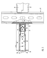
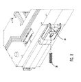
Figure 1 is a side view of a base mounted on a DIN rail; -
Figure 2 is a bottom view ofFigure 1 ; -
Figure 3 is a view likeFigure 2 , partially broken away; -
Figure 4 is an enlarged view of a portion ofFigure 1 , partially broken away; -
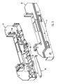
Figure 5 is an exploded view of a base illustrating the position of a release member for assembly in the base; -
Figure 6 is a sectional view similar toFigure 3 showing the release member in a retracted loading position in the shells forming the base; -
Figure 7 is a sectional view showing mounting of the DIN rail latch member on the release member in the position shown inFigure 6 ; -
Figure 8 is a perspective view illustrating insertion of a return spring into the latch member mounted on the release member; -
Figure 9 is a perspective view of the release member; and -
Figures 10 and 11 are perspective views of the top and bottom of the DIN latch member. -
Power supply base 10 is removably mounted on elongate DIN rail orsupport 12 by DINrail hook 14 on the bottom of the base and DINrail latch assembly 16 on the bottom of the base on the opposite side of the rail fromhook 14. Thebase 10 includes a hollowplastic body 18 formed from twohollow shells rail 12 and an actuation location atbase end 54. -
Module recess 24 is formed at the top of thebase 10. A power conditioning module may be mounted inrecess 24 for electrical connection with electronic components in the base, conductors in a process fieldbus connected to the base and a DC power source for the process fieldbus. The process fieldbus conductors and power supply conductors are connected to contact members on the base (not illustrated). Other types of electronic modules may be mounted inrecess 24. - A power conditioning module mounted on
base 10 regulates the voltage of the DC power supplied to the process fieldbus independent of the voltage of the power supplied to the module from a DC power source. The components in the base may include a circuit board assembly for connecting to the process fieldbus, the power conditioning module and the DC power source (not illustrated). - A number of
bases 10 are conventionally stacked together side-by-side and are mounted onDIN rail 12. Bridging connectors (not illustrated) extend throughconnector openings 26 formed in the opposite sides ofbase 10 to establish electrical connection between components in adjacent bases. - DIN
rail 12 includes an elongate,flat base 28 which is typically mounted on a support surface, side walls 30 extending upwardly frombase 28 and outwardly extendingmounting flanges 32 at the tops of the side walls. - DIN
rail latch assembly 16 includes ametal latch member 34 mounted on the bottom ofbody 18 adjacent one side ofrail 12. Thelatch member 34 is freely movable toward and away from the DIN rail whenassembly 16 is operative.Spring 36 biases the latch member toward the DIN rail to engage theadjacent mounting flange 32.Assembly 16 also includes a flat,elongate release member 38 which is mounted on the bottom ofbody 18 and is connected to the latch member. When the latch assembly is in the operative position shown inFigures 1-4 , it is movable toward and away fromrail 12.Member 38 is pulled outwardly from the base to release thelatch member 34 from the rail for removal of the base from the rail. -
Release member 38 is positioned in a steppedhorizontal groove 40 formed the bottom ofbody 18 to one side ofrail 12. Thegroove 40 has a downwardly facing surface which extends along the seam between the shells and includes a wideouter portion 42 extending frombase end 54 togroove step 44 and a narrow,inner portion 46 extending fromstep 44 to aninner end 47 adjacent the DIN rail.Step 44 extends outwardly to either side ofnarrow groove portion 46. -
Release member 38 is formed from metal strip stock and includesflat body 39 having awide portion 48 located inwide groove portion 42 and anarrow portion 50 located innarrow groove portion 46. Thewide portion 48 ofrelease member 38 provides greater strength and stability for theouter end 52 of the member which is engaged to shift theassembly 16. The inner end of the release member is narrow in order to engage narrowlatch member 34. Taperedouter end 52 ofrelease member 38 extends outwardly fromadjacent base end 54 at the actuation location.Engagement opening 56 is provided inactuator end 52 ofrelease member 38 to facilitate outward shifting ofassembly 16 using a tool to release the base from the DIN rail. Therelease member 38 includes inwardly extendingshoulders 58 between the wide andnarrow portions - A pair of spaced apart mounting or
attachment fingers 60 extend down from the inner end ofnarrow strip portion 50.Center mounting finger 62 is located between fingers 60 a short distance beyondfingers 60.Fingers portion 50 and are bent back towardportion 50 at an angle of 88°, shown as angle X inFigure 9 .Mounting arm 78 extends up frombase 70 and is bent forward of thebase 70 at an angle of 92°. The two nominal angles are supplementary. The interengagement between the angled or rakedfingers raked arm 78 forms a locked connection between the fingers and arm to prevent disengagement of the release and latch members whenouter end 52 ofmember 38 is pulled to movelatch member 34 and unlatch the base from the DIN rail. - As illustrated best in
Figures 3 and9 ,projections 64 at the inner end of widerelease member portion 48 extend a short distance outwardly from the opposed, parallel sides ofportion 48 atshoulders 58. -
Wide groove portion 42 has opposed,parallel walls 66 extending frombase end 54 inwardly to a short distance before steps 44. SeeFigure 6 .Recesses 68 insides 66 extend from the steps 44 a distance towardbase end 54 and increase the width ofgroove 40 adjacent thestep 44 to a distance slightly greater than the width ofrelease member 38 atprojections 64. The width ofwide strip portion 48 away fromprojections 64 has a close, sliding fit inwide groove portion 42 betweensides 66 as illustrated inFigure 6 .Narrow portion 50 has a close, sliding fit ingroove portion 46. During assembly ofbase 10,release member 38 is held in place in steppedgroove 40 in an assembly position.Shoulders 58 are spaced away fromsteps 44.Projections 64 frictionally engagesides 66 adjacent groove recesses 68 to holdmember 38 in the assembly position, as shown inFigure 6 and described below. -
Latch member 34 is shown inFigures 10 and 11 . Themember 34 has aflat base 70, 90-degree side walls 72 which extend up from the base from opposed base sides, and inwardlybent retention arms 74 extending over the base from the tops of the side walls. Spring access opening 76 is formed through the center ofbase 70.Attachment arm 78 extends upwardly frombase 70 inwardly of opening 76 and includes a small outwardly facingspring alignment dimple 80 as shown inFigure 7 .Latches 82 are formed on the lead ends ofside walls 72 and each include an angled lead-in orcam surface 84 and aretention notch 86. - Assembly of the DIN
rail latch assembly 16 onbody 18 will now be described. Electronic components are mounted inshell body 18 at the same time the latch assembly is mounted in the body. Mounting of the components inbody 18 is not described. - The
latch assembly 16 is mounted inshell body 18 by firstpositioning release member 38 in the part ofgroove 40 in one of theopen shells outer end 52 extending a distance outwardly from theend 54 of the shell greater than when in the normal operative position ofend 52. Theprojection 64 engages theside 66 of the groove in the position shown inFigure 6 and does not extend into theadjacent groove recess 68. The mountingfingers base 10.Figure 6 shows therelease member 38 in the assembly position. - With the release member in the assembly position in one
shell second shell shell Posts 88 are shown on the interface ofshell 22 illustrated inFigure 5 . Complementary recesses are provided on the interface ofshell 20. With theshells groove 40 in the assembly position shown inFigure 6 withprojections 64 engaging thesides 66 ofwide groove portion 42 to prevent movement of the release member alonggroove 40.Narrow portion 50 ofrelease member 38 extends intogroove portion 46 and thefingers latch window 90 located at the inner end of the release member as shown inFigures 6 and7 . - Next,
latch member 34 is positioned belowwindow 90 and is moved upwardly to extend mountingarm 78 betweenfingers window 90 and move theretention arms 74 against the bottom surfaces 94 ofshells walls 96 forming the sides ofnarrow groove portion 46.Dimple 80 extends betweenfingers 60 and is in position to locatespring 36 inmember 34. -
Latch member arms 74 rest against shell bottom surfaces 94 at assembly. Thesidewalls 72 of the latch member are located on the outer sides ofwalls 96. The twoarms 74 nearest thelatches 82 are guided during assembly by channels betweenretention projections 98 extending outwardly fromwalls 96. The twoarms 74 positioned away fromlatches 82 are similarly guided during assembly by channels betweenretention projections 98 and the outer walls of groove steps 44. SeeFigure 6 . - Next, the
outer end 52 ofrelease member 38 is pushed intobody 18 to moveprojections 64 out of interference engagement withgroove sides 66 and intorecesses 68. At the same time, thelatch member 34 is pushed inwardly and thearms 74 are moved under overhanging features inretention projections 98 to secure the latch member onbody 18. - With the
latch member 34 andrelease member 38 positioned inwardly,spring 36 is compressed and moved through access opening 76 inlatch member base 70 and released. One end of the spring fits overdimple 80 onlatch member arm 78. The other end of the spring engageswall 100 at the outer side oflatch window 90. Withrelease member projections 64 movable freely inrecesses 68, the joinedrelease member 38 andlatch member 34 are in the operative position and are movable toward and away from the DIN rail.Spring 36 normally holds the members in the inner, latched position shown inFigure 4 . Outward movement ofrelease member end 52, typically by inserting a tool in opening 56 and moving the tool away frombase end 54, moves themembers spring 36 compressed betweenarm 78 andwall 100. During movement of thelatch member 34 between the latched and unlatched positions, theouter arms 74 remain underprojections 98 to retain the latch member on the bottom ofbody 18. - The assembled
power supply base 10 is mounted on DIN rail by loweringrail hook 14 below oneDIN rail flange 32 and then moving thehook 14 under the flange with the base angled upwardly above the rail. The base is then rotated down so that theother flange 32 engages angled lead-in or cam surfaces 84 onlatch member 34. Downward rotation cams the latch member and release member outwardly until theflange 32 moves past lead-insurfaces 84 and compressedspring 36 returns themembers Figure 1 . In this position, the adjacentDIN rail flange 32 is seated inretention notches 86 andbase 10 is mounted onrail 12. - The base is removed from the rail by gripping the
outer end 52 ofrelease member 38 and moving the end outwardly to retractlatch member 34 from engagement with the adjacentDIN rail flange 32. The base assembly is then rotated up around the recess underhook 14 and freed fromrail 12.
Claims (15)
- A base for mounting on a DIN rail, the base comprising a body and a latch assembly; the body including an interior cavity for an electronic component, a surface extending between a DIN rail location and an actuation location, a retention member adjacent the DIN rail location, a first wall extending along said surface, and a first recess in said first wall; said latch assembly including a release member on the surface and extending along the wall, an actuator at said actuation location, a first attachment member adjacent the DIN rail location, and a first projection on a side of the release member adjacent the wall; and a latch member adjacent the DIN rail location, the latch member including a second attachment member engageable with said first attachment member to mount the latch member on the release member, and a latch engageable with a DIN rail; the release member having an assembly position away from the DIN rail location with said projection physically engaging the wall adjacent the recess to prevent movement of the release member along the surface and permit mounting of the latch member on the release member by engagement between said first and second attachment members; said latch assembly having an operative position where the release member is closer to the DIN rail location than when in the assembly position, the first projection is in said first recess, a portion of the latch member engages the retention member to secure the latch member on the base, and the latch assembly is movable toward and away from the DIN rail location to engage a DIN rail.
- The base as in claim 1 including a spring biasing the latch assembly toward the DIN rail location.
- The base as in claim 2 wherein said surface is flat and the release member includes a flat strip movable along said surface.
- The base as in claim 3 wherein said first wall and said first recess are on one side of the surface and including a second wall and a second recess on an opposite side of said surface, the release member including a second projection adjacent said second side, said second projection engaging said second side when the release member is in the assembly position and said second projection in said second recess when the latch assembly is in the operative position.
- The base as in claim 3 wherein the width of the strip adjacent the actuation location is greater than the width of the strip adjacent the DIN rail location.
- The base as in claim 3 wherein said retention member comprises a retention projection on the base and the latch member includes an arm engageable with the retention member when the latch assembly is in the operative position.
- The base as in claim 3 wherein the base includes a DIN rail hook at the DIN rail location, said latch member and DIN rail hook engageable with flanges on opposite sides of a DIN rail to mount the base on the rail.
- The base as in claim 3 including a recess on the base for mounting a module.
- The combination of a power supply base as in claim 8 and a power conditioning module in said recess.
- The base as in claim 3 including a locked connection between the release member and the latch member when the latch assembly is in the operative position.
- A base for latch mounting on a support, the base comprising a body and a latch assembly; the body including a surface extending between a support location and an actuation location, a retention member adjacent the support location, a first wall extending along said surface, and a first recess in said first wall; said latch assembly including a release member on the surface and extending along said wall, an actuator at said actuation location, a first attachment member adjacent the support location, and a first projection on a side of the release member adjacent the wall; and a latch member adjacent the support location, the latch member including a second attachment member engageable with said first attachment member to mount the latch member on the release member, and a latch engageable with a support; the release member having an assembly position away from the support location with said projection physically engaging the wall adjacent the recess to prevent movement of the release member along the surface and permit mounting of the latch member on the release member by engagement between said first and second attachment members; said latch assembly having an operative position where the release member is closer to the support location than when in the assembly position, the first projection is in said first recess, a portion of the latch member engages the retention member to secure the latch member on the base, and the latch assembly is movable toward and away from the support location to engage a support.
- The base as in claim 11 including a spring biasing the latch assembly toward the support location.
- The base as in claim 12 wherein said surface is flat and the release member includes a flat strip movable along said surface.
- The base as in claim 13 wherein said first wall and said first recess are on one side of the surface and including a second wall and a second recess on an opposite side of said surface, the release member including a second projection adjacent said second side, said second projection engaging said second side when the release member is in the assembly position and said second projection in said second recess when the latch assembly is in the operative position.
- The base as in claim 14 including a locked connection between the release member and the latch member when the latch assembly is in the operative position, comprising a first angled member on the release member, a second angled member on the latch member positioned outwardly from and overlying the first angled member so that outward movement of the release member locks such members for movement of the latch member away from the support location.
Applications Claiming Priority (1)
| Application Number | Priority Date | Filing Date | Title |
|---|---|---|---|
| US13/069,644 US8226433B1 (en) | 2011-03-23 | 2011-03-23 | Latch assembly for mounting power supply base for a process fieldbus on a DIN rail and method |
Publications (3)
| Publication Number | Publication Date |
|---|---|
| EP2503645A2 true EP2503645A2 (en) | 2012-09-26 |
| EP2503645A3 EP2503645A3 (en) | 2013-05-01 |
| EP2503645B1 EP2503645B1 (en) | 2021-07-14 |
Family
ID=45976032
Family Applications (1)
| Application Number | Title | Priority Date | Filing Date |
|---|---|---|---|
| EP12002035.9A Active EP2503645B1 (en) | 2011-03-23 | 2012-03-22 | Latch assembly for mounting power supply base for a process fieldbus on a support |
Country Status (4)
| Country | Link |
|---|---|
| US (2) | US8226433B1 (en) |
| EP (1) | EP2503645B1 (en) |
| JP (1) | JP5420007B2 (en) |
| CN (1) | CN102695397B (en) |
Cited By (1)
| Publication number | Priority date | Publication date | Assignee | Title |
|---|---|---|---|---|
| AU2018203535B2 (en) * | 2017-05-23 | 2020-01-16 | Schneider Electric Industries Sas | Locking clip for fixing low voltage power distribution terminal product to supporting device |
Families Citing this family (24)
| Publication number | Priority date | Publication date | Assignee | Title |
|---|---|---|---|---|
| EP2551973B1 (en) * | 2011-07-28 | 2016-03-23 | ABB Technology AG | Clamping element |
| EP2626962A1 (en) * | 2012-02-13 | 2013-08-14 | Siemens Aktiengesellschaft | Clamping assembly for fixing a housing to a rail |
| CN103260376B (en) * | 2012-02-16 | 2017-03-22 | 富泰华工业(深圳)有限公司 | Retainer and electrical element installing fixing device with retainer |
| US9331404B2 (en) * | 2013-01-17 | 2016-05-03 | Asco Power Technologies, L.P. | DIN rail latching arrangement |
| US9125317B2 (en) * | 2013-03-15 | 2015-09-01 | Cisco Technology, Inc. | DIN rail mount bracket |
| US9353777B2 (en) * | 2013-07-09 | 2016-05-31 | Rockwell Automation Technologies, Inc. | Method and apparatus to attach device to DIN rail |
| WO2015048428A1 (en) * | 2013-09-26 | 2015-04-02 | Abb Technology Ag | Rail-mounted control system |
| US9727098B2 (en) * | 2014-06-16 | 2017-08-08 | Phoenix Contact Development and Manufacturing, Inc. | Redundant power supply motherboard assembly |
| US9374924B2 (en) * | 2014-09-16 | 2016-06-21 | Schneider Electric Buildings, Llc | DIN rail mounted enclosure assembly and method of use |
| US9485879B2 (en) * | 2015-03-06 | 2016-11-01 | Rockwell Automation Technologies, Inc. | Single action DIN rail latch |
| TWI589213B (en) * | 2015-03-30 | 2017-06-21 | 台達電子工業股份有限公司 | Clip and electronic device using same |
| CN106163198B (en) * | 2015-03-30 | 2019-04-12 | 台达电子工业股份有限公司 | Buckle clamp and applicable electronic device thereof |
| EP3208900B1 (en) * | 2016-02-16 | 2020-04-29 | FRIWO Gerätebau GmbH | Electrical device for rail mounting |
| TWM541651U (en) * | 2016-10-21 | 2017-05-11 | 啓碁科技股份有限公司 | Suspension mount |
| CN208157658U (en) * | 2018-03-27 | 2018-11-27 | 菲尼克斯亚太电气(南京)有限公司 | A kind of bolt terminal |
| US10971864B1 (en) * | 2019-09-30 | 2021-04-06 | BAKC Capital Group | DIN rail shield |
| US11284527B2 (en) | 2020-03-03 | 2022-03-22 | Hewlett Packard Enterprise Development Lp | Latch assembly for a modular device |
| TWI737440B (en) * | 2020-08-10 | 2021-08-21 | 啓碁科技股份有限公司 | Suspension mounting structure |
| DE102020125381A1 (en) * | 2020-09-29 | 2022-03-31 | Harting Electric Gmbh & Co. Kg | Fastening system for connectors |
| US11828481B2 (en) | 2020-10-16 | 2023-11-28 | Honeywell International, Inc. | Building controller with adaptable mount |
| US11576275B2 (en) * | 2021-02-26 | 2023-02-07 | Adlink Technology Inc. | DIN rail installation kit and its operation method |
| US12107377B2 (en) | 2021-09-14 | 2024-10-01 | Appleton Grp Llc | Plastic latching system for securement of electronic component to a DIN rail |
| US12369267B2 (en) * | 2022-03-30 | 2025-07-22 | Abb Schweiz Ag | Carrier module apparatus for retrofit in control cabinets and methods of assembly thereof |
| US12513843B2 (en) * | 2024-04-24 | 2025-12-30 | Schneider Electric Buildings Americas, Inc. | DIN rail and wall mounted enclosure assembly and method of use |
Family Cites Families (21)
| Publication number | Priority date | Publication date | Assignee | Title |
|---|---|---|---|---|
| DE3149310A1 (en) * | 1981-12-12 | 1983-06-16 | Brown, Boveri & Cie Ag, 6800 Mannheim | Device and method for attachment of electrical installation apparatuses on standard profiled rails, especially on cap profiled rails |
| JPS6138979U (en) * | 1984-08-09 | 1986-03-11 | 三菱電機株式会社 | Electrical equipment mounting equipment |
| JPS6286800A (en) * | 1985-10-12 | 1987-04-21 | 三菱電機株式会社 | Apparatus for attaching rail of electric machine |
| JPH0526791Y2 (en) * | 1987-03-28 | 1993-07-07 | ||
| IT1223521B (en) * | 1987-12-17 | 1990-09-19 | Elettrocondutture | DEVICE FOR RELEASING THE QUICK COUPLINGS USED FOR THE FIXING OF MODULAR DEVICES TO THE RELEVANT SUPPORT PROFILES |
| US4900275A (en) * | 1989-05-18 | 1990-02-13 | Carlingswitch, Inc. | DIN rail mountable circuit breaker |
| DE4011447C2 (en) * | 1990-04-09 | 1998-03-19 | Abb Patent Gmbh | Device for snap fastening an electrical installation device |
| JPH0412691U (en) * | 1990-05-24 | 1992-01-31 | ||
| JPH08139472A (en) * | 1994-11-11 | 1996-05-31 | Sunx Ltd | Structure for mounting electronic device on rail |
| US6292076B1 (en) | 1999-08-30 | 2001-09-18 | Eaton Corporation | Circuit interrupter with improved DIN rail mounting adaptor |
| US7059898B2 (en) * | 2004-10-13 | 2006-06-13 | Rockwell Automation Technologies, Inc. | DIN rail latching system and method |
| DE102006049019B4 (en) | 2006-10-13 | 2009-11-26 | Phoenix Contact Gmbh & Co. Kg | Mounting plate with fixing means for an electrical device |
| TWI308859B (en) | 2006-11-03 | 2009-04-11 | Delta Electronics Thailand Public Co Ltd | A detachable electronic device and a latching structure thereof |
| DE102006057766B4 (en) | 2006-12-07 | 2010-02-04 | Siemens Ag | Fastening device of electronic modules on mounting rail |
| US7758368B2 (en) * | 2007-05-29 | 2010-07-20 | Honeywell International Inc. | DIN rail mount |
| ES2370669T3 (en) * | 2008-06-23 | 2011-12-21 | Abb Schweiz Ag | HOUSING WITH LOCK ELEMENT. |
| US7674129B1 (en) | 2008-12-22 | 2010-03-09 | Moxa Inc. | Clamping device for DIN rail |
| DK2259396T3 (en) * | 2009-06-05 | 2016-08-01 | Schneider Electric Ind Sas | Device for locking a component on a rail |
| US8066239B2 (en) * | 2009-06-15 | 2011-11-29 | Rockwell Automation Technologies, Inc. | Integrated DIN rail attachment feature for superior attachment |
| JP5270479B2 (en) * | 2009-07-10 | 2013-08-21 | 三菱電機株式会社 | Mounting device for electrical equipment and circuit breaker provided with the mounting device |
| US20110269339A1 (en) * | 2010-04-30 | 2011-11-03 | Rockwell Automation Technologies, Inc. | System for securing a device using two din rails |
-
2011
- 2011-03-23 US US13/069,644 patent/US8226433B1/en not_active Expired - Fee Related
-
2012
- 2012-03-22 EP EP12002035.9A patent/EP2503645B1/en active Active
- 2012-03-22 JP JP2012064985A patent/JP5420007B2/en not_active Expired - Fee Related
- 2012-03-23 CN CN201210092899.5A patent/CN102695397B/en not_active Expired - Fee Related
- 2012-06-26 US US13/533,157 patent/US8469737B2/en active Active
Non-Patent Citations (1)
| Title |
|---|
| None |
Cited By (1)
| Publication number | Priority date | Publication date | Assignee | Title |
|---|---|---|---|---|
| AU2018203535B2 (en) * | 2017-05-23 | 2020-01-16 | Schneider Electric Industries Sas | Locking clip for fixing low voltage power distribution terminal product to supporting device |
Also Published As
| Publication number | Publication date |
|---|---|
| EP2503645A3 (en) | 2013-05-01 |
| US8226433B1 (en) | 2012-07-24 |
| CN102695397B (en) | 2015-11-25 |
| US20120260485A1 (en) | 2012-10-18 |
| EP2503645B1 (en) | 2021-07-14 |
| CN102695397A (en) | 2012-09-26 |
| US8469737B2 (en) | 2013-06-25 |
| JP5420007B2 (en) | 2014-02-19 |
| JP2012204344A (en) | 2012-10-22 |
Similar Documents
| Publication | Publication Date | Title |
|---|---|---|
| US8226433B1 (en) | Latch assembly for mounting power supply base for a process fieldbus on a DIN rail and method | |
| KR101797249B1 (en) | Connector terminal position assurance device | |
| KR102272312B1 (en) | Connector with terminal position assurance | |
| JP4638557B2 (en) | Connector positioning element and connector assembly apparatus incorporating the same | |
| US8267717B2 (en) | FPC connector having rotating actuator | |
| US10923847B2 (en) | Male terminal position assurance (TPA) device for a connector and method for assembling thereof | |
| US6881081B2 (en) | Electrical connector assembly with connection assurance features | |
| JPH0422079A (en) | Connector | |
| WO2015016771A1 (en) | Dual-motion mating assisted connector | |
| US20060172597A1 (en) | Connector and a method of assembling it | |
| US8435051B2 (en) | Board connector and method of mounting it | |
| JP4228984B2 (en) | connector | |
| EP2503864A2 (en) | Latch and extractor for electronic module | |
| KR20090071000A (en) | connector | |
| CA2499919C (en) | Adjustable pin header assembly and method of manufacture | |
| JP6337154B2 (en) | Adapter for mounting a single-pin or multi-pin overvoltage protection device designed as a plug-in module and method of using such an adapter | |
| KR101442537B1 (en) | Lever jig and connector device | |
| JP4420014B2 (en) | Electrical connection box for automobile | |
| US6953364B2 (en) | Connector, a shorting terminal and a method of assembling it | |
| JP3436113B2 (en) | connector | |
| JP2008198392A (en) | Joint connector | |
| JP2005302350A (en) | Connector | |
| JPH03194872A (en) | Electric connector with lock mechanism | |
| JP2004200075A (en) | Connector |
Legal Events
| Date | Code | Title | Description |
|---|---|---|---|
| PUAI | Public reference made under article 153(3) epc to a published international application that has entered the european phase |
Free format text: ORIGINAL CODE: 0009012 |
|
| AK | Designated contracting states |
Kind code of ref document: A2 Designated state(s): AL AT BE BG CH CY CZ DE DK EE ES FI FR GB GR HR HU IE IS IT LI LT LU LV MC MK MT NL NO PL PT RO RS SE SI SK SM TR |
|
| AX | Request for extension of the european patent |
Extension state: BA ME |
|
| RIN1 | Information on inventor provided before grant (corrected) |
Inventor name: CORRELL, MICHAEL ANTHONY Inventor name: BARBER, TERRY LEE |
|
| RAP1 | Party data changed (applicant data changed or rights of an application transferred) |
Owner name: PHOENIX CONTACT GMBH & CO. KG |
|
| PUAL | Search report despatched |
Free format text: ORIGINAL CODE: 0009013 |
|
| AK | Designated contracting states |
Kind code of ref document: A3 Designated state(s): AL AT BE BG CH CY CZ DE DK EE ES FI FR GB GR HR HU IE IS IT LI LT LU LV MC MK MT NL NO PL PT RO RS SE SI SK SM TR |
|
| AX | Request for extension of the european patent |
Extension state: BA ME |
|
| RIC1 | Information provided on ipc code assigned before grant |
Ipc: H01R 9/26 20060101AFI20130328BHEP |
|
| 17P | Request for examination filed |
Effective date: 20131104 |
|
| RBV | Designated contracting states (corrected) |
Designated state(s): AL AT BE BG CH CY CZ DE DK EE ES FI FR GB GR HR HU IE IS IT LI LT LU LV MC MK MT NL NO PL PT RO RS SE SI SK SM TR |
|
| STAA | Information on the status of an ep patent application or granted ep patent |
Free format text: STATUS: EXAMINATION IS IN PROGRESS |
|
| 17Q | First examination report despatched |
Effective date: 20171106 |
|
| GRAP | Despatch of communication of intention to grant a patent |
Free format text: ORIGINAL CODE: EPIDOSNIGR1 |
|
| STAA | Information on the status of an ep patent application or granted ep patent |
Free format text: STATUS: GRANT OF PATENT IS INTENDED |
|
| INTG | Intention to grant announced |
Effective date: 20191018 |
|
| GRAJ | Information related to disapproval of communication of intention to grant by the applicant or resumption of examination proceedings by the epo deleted |
Free format text: ORIGINAL CODE: EPIDOSDIGR1 |
|
| STAA | Information on the status of an ep patent application or granted ep patent |
Free format text: STATUS: EXAMINATION IS IN PROGRESS |
|
| INTC | Intention to grant announced (deleted) | ||
| GRAP | Despatch of communication of intention to grant a patent |
Free format text: ORIGINAL CODE: EPIDOSNIGR1 |
|
| STAA | Information on the status of an ep patent application or granted ep patent |
Free format text: STATUS: GRANT OF PATENT IS INTENDED |
|
| INTG | Intention to grant announced |
Effective date: 20210318 |
|
| GRAS | Grant fee paid |
Free format text: ORIGINAL CODE: EPIDOSNIGR3 |
|
| GRAA | (expected) grant |
Free format text: ORIGINAL CODE: 0009210 |
|
| STAA | Information on the status of an ep patent application or granted ep patent |
Free format text: STATUS: THE PATENT HAS BEEN GRANTED |
|
| AK | Designated contracting states |
Kind code of ref document: B1 Designated state(s): AL AT BE BG CH CY CZ DE DK EE ES FI FR GB GR HR HU IE IS IT LI LT LU LV MC MK MT NL NO PL PT RO RS SE SI SK SM TR |
|
| REG | Reference to a national code |
Ref country code: GB Ref legal event code: FG4D |
|
| REG | Reference to a national code |
Ref country code: IE Ref legal event code: FG4D |
|
| REG | Reference to a national code |
Ref country code: DE Ref legal event code: R096 Ref document number: 602012076090 Country of ref document: DE |
|
| REG | Reference to a national code |
Ref country code: AT Ref legal event code: REF Ref document number: 1411377 Country of ref document: AT Kind code of ref document: T Effective date: 20210815 |
|
| REG | Reference to a national code |
Ref country code: LT Ref legal event code: MG9D |
|
| REG | Reference to a national code |
Ref country code: NL Ref legal event code: MP Effective date: 20210714 |
|
| REG | Reference to a national code |
Ref country code: AT Ref legal event code: MK05 Ref document number: 1411377 Country of ref document: AT Kind code of ref document: T Effective date: 20210714 |
|
| PG25 | Lapsed in a contracting state [announced via postgrant information from national office to epo] |
Ref country code: FI Free format text: LAPSE BECAUSE OF FAILURE TO SUBMIT A TRANSLATION OF THE DESCRIPTION OR TO PAY THE FEE WITHIN THE PRESCRIBED TIME-LIMIT Effective date: 20210714 Ref country code: ES Free format text: LAPSE BECAUSE OF FAILURE TO SUBMIT A TRANSLATION OF THE DESCRIPTION OR TO PAY THE FEE WITHIN THE PRESCRIBED TIME-LIMIT Effective date: 20210714 Ref country code: NL Free format text: LAPSE BECAUSE OF FAILURE TO SUBMIT A TRANSLATION OF THE DESCRIPTION OR TO PAY THE FEE WITHIN THE PRESCRIBED TIME-LIMIT Effective date: 20210714 Ref country code: NO Free format text: LAPSE BECAUSE OF FAILURE TO SUBMIT A TRANSLATION OF THE DESCRIPTION OR TO PAY THE FEE WITHIN THE PRESCRIBED TIME-LIMIT Effective date: 20211014 Ref country code: PT Free format text: LAPSE BECAUSE OF FAILURE TO SUBMIT A TRANSLATION OF THE DESCRIPTION OR TO PAY THE FEE WITHIN THE PRESCRIBED TIME-LIMIT Effective date: 20211115 Ref country code: RS Free format text: LAPSE BECAUSE OF FAILURE TO SUBMIT A TRANSLATION OF THE DESCRIPTION OR TO PAY THE FEE WITHIN THE PRESCRIBED TIME-LIMIT Effective date: 20210714 Ref country code: AT Free format text: LAPSE BECAUSE OF FAILURE TO SUBMIT A TRANSLATION OF THE DESCRIPTION OR TO PAY THE FEE WITHIN THE PRESCRIBED TIME-LIMIT Effective date: 20210714 Ref country code: BG Free format text: LAPSE BECAUSE OF FAILURE TO SUBMIT A TRANSLATION OF THE DESCRIPTION OR TO PAY THE FEE WITHIN THE PRESCRIBED TIME-LIMIT Effective date: 20211014 Ref country code: LT Free format text: LAPSE BECAUSE OF FAILURE TO SUBMIT A TRANSLATION OF THE DESCRIPTION OR TO PAY THE FEE WITHIN THE PRESCRIBED TIME-LIMIT Effective date: 20210714 Ref country code: HR Free format text: LAPSE BECAUSE OF FAILURE TO SUBMIT A TRANSLATION OF THE DESCRIPTION OR TO PAY THE FEE WITHIN THE PRESCRIBED TIME-LIMIT Effective date: 20210714 Ref country code: SE Free format text: LAPSE BECAUSE OF FAILURE TO SUBMIT A TRANSLATION OF THE DESCRIPTION OR TO PAY THE FEE WITHIN THE PRESCRIBED TIME-LIMIT Effective date: 20210714 |
|
| PG25 | Lapsed in a contracting state [announced via postgrant information from national office to epo] |
Ref country code: PL Free format text: LAPSE BECAUSE OF FAILURE TO SUBMIT A TRANSLATION OF THE DESCRIPTION OR TO PAY THE FEE WITHIN THE PRESCRIBED TIME-LIMIT Effective date: 20210714 Ref country code: LV Free format text: LAPSE BECAUSE OF FAILURE TO SUBMIT A TRANSLATION OF THE DESCRIPTION OR TO PAY THE FEE WITHIN THE PRESCRIBED TIME-LIMIT Effective date: 20210714 Ref country code: GR Free format text: LAPSE BECAUSE OF FAILURE TO SUBMIT A TRANSLATION OF THE DESCRIPTION OR TO PAY THE FEE WITHIN THE PRESCRIBED TIME-LIMIT Effective date: 20211015 |
|
| REG | Reference to a national code |
Ref country code: DE Ref legal event code: R097 Ref document number: 602012076090 Country of ref document: DE |
|
| PG25 | Lapsed in a contracting state [announced via postgrant information from national office to epo] |
Ref country code: DK Free format text: LAPSE BECAUSE OF FAILURE TO SUBMIT A TRANSLATION OF THE DESCRIPTION OR TO PAY THE FEE WITHIN THE PRESCRIBED TIME-LIMIT Effective date: 20210714 |
|
| PLBE | No opposition filed within time limit |
Free format text: ORIGINAL CODE: 0009261 |
|
| STAA | Information on the status of an ep patent application or granted ep patent |
Free format text: STATUS: NO OPPOSITION FILED WITHIN TIME LIMIT |
|
| PG25 | Lapsed in a contracting state [announced via postgrant information from national office to epo] |
Ref country code: SM Free format text: LAPSE BECAUSE OF FAILURE TO SUBMIT A TRANSLATION OF THE DESCRIPTION OR TO PAY THE FEE WITHIN THE PRESCRIBED TIME-LIMIT Effective date: 20210714 Ref country code: SK Free format text: LAPSE BECAUSE OF FAILURE TO SUBMIT A TRANSLATION OF THE DESCRIPTION OR TO PAY THE FEE WITHIN THE PRESCRIBED TIME-LIMIT Effective date: 20210714 Ref country code: RO Free format text: LAPSE BECAUSE OF FAILURE TO SUBMIT A TRANSLATION OF THE DESCRIPTION OR TO PAY THE FEE WITHIN THE PRESCRIBED TIME-LIMIT Effective date: 20210714 Ref country code: EE Free format text: LAPSE BECAUSE OF FAILURE TO SUBMIT A TRANSLATION OF THE DESCRIPTION OR TO PAY THE FEE WITHIN THE PRESCRIBED TIME-LIMIT Effective date: 20210714 Ref country code: CZ Free format text: LAPSE BECAUSE OF FAILURE TO SUBMIT A TRANSLATION OF THE DESCRIPTION OR TO PAY THE FEE WITHIN THE PRESCRIBED TIME-LIMIT Effective date: 20210714 Ref country code: AL Free format text: LAPSE BECAUSE OF FAILURE TO SUBMIT A TRANSLATION OF THE DESCRIPTION OR TO PAY THE FEE WITHIN THE PRESCRIBED TIME-LIMIT Effective date: 20210714 |
|
| 26N | No opposition filed |
Effective date: 20220419 |
|
| PG25 | Lapsed in a contracting state [announced via postgrant information from national office to epo] |
Ref country code: MC Free format text: LAPSE BECAUSE OF FAILURE TO SUBMIT A TRANSLATION OF THE DESCRIPTION OR TO PAY THE FEE WITHIN THE PRESCRIBED TIME-LIMIT Effective date: 20210714 |
|
| REG | Reference to a national code |
Ref country code: CH Ref legal event code: PL |
|
| REG | Reference to a national code |
Ref country code: BE Ref legal event code: MM Effective date: 20220331 |
|
| PG25 | Lapsed in a contracting state [announced via postgrant information from national office to epo] |
Ref country code: LU Free format text: LAPSE BECAUSE OF NON-PAYMENT OF DUE FEES Effective date: 20220322 Ref country code: LI Free format text: LAPSE BECAUSE OF NON-PAYMENT OF DUE FEES Effective date: 20220331 Ref country code: IE Free format text: LAPSE BECAUSE OF NON-PAYMENT OF DUE FEES Effective date: 20220322 Ref country code: CH Free format text: LAPSE BECAUSE OF NON-PAYMENT OF DUE FEES Effective date: 20220331 |
|
| PG25 | Lapsed in a contracting state [announced via postgrant information from national office to epo] |
Ref country code: BE Free format text: LAPSE BECAUSE OF NON-PAYMENT OF DUE FEES Effective date: 20220331 |
|
| P01 | Opt-out of the competence of the unified patent court (upc) registered |
Effective date: 20230424 |
|
| PG25 | Lapsed in a contracting state [announced via postgrant information from national office to epo] |
Ref country code: HU Free format text: LAPSE BECAUSE OF FAILURE TO SUBMIT A TRANSLATION OF THE DESCRIPTION OR TO PAY THE FEE WITHIN THE PRESCRIBED TIME-LIMIT; INVALID AB INITIO Effective date: 20120322 |
|
| PG25 | Lapsed in a contracting state [announced via postgrant information from national office to epo] |
Ref country code: MK Free format text: LAPSE BECAUSE OF FAILURE TO SUBMIT A TRANSLATION OF THE DESCRIPTION OR TO PAY THE FEE WITHIN THE PRESCRIBED TIME-LIMIT Effective date: 20210714 Ref country code: CY Free format text: LAPSE BECAUSE OF FAILURE TO SUBMIT A TRANSLATION OF THE DESCRIPTION OR TO PAY THE FEE WITHIN THE PRESCRIBED TIME-LIMIT Effective date: 20210714 |
|
| PGFP | Annual fee paid to national office [announced via postgrant information from national office to epo] |
Ref country code: GB Payment date: 20240319 Year of fee payment: 13 |
|
| PGFP | Annual fee paid to national office [announced via postgrant information from national office to epo] |
Ref country code: IT Payment date: 20240321 Year of fee payment: 13 Ref country code: FR Payment date: 20240326 Year of fee payment: 13 |
|
| PG25 | Lapsed in a contracting state [announced via postgrant information from national office to epo] |
Ref country code: TR Free format text: LAPSE BECAUSE OF FAILURE TO SUBMIT A TRANSLATION OF THE DESCRIPTION OR TO PAY THE FEE WITHIN THE PRESCRIBED TIME-LIMIT Effective date: 20210714 |
|
| PGFP | Annual fee paid to national office [announced via postgrant information from national office to epo] |
Ref country code: DE Payment date: 20240529 Year of fee payment: 13 |
|
| PG25 | Lapsed in a contracting state [announced via postgrant information from national office to epo] |
Ref country code: MT Free format text: LAPSE BECAUSE OF FAILURE TO SUBMIT A TRANSLATION OF THE DESCRIPTION OR TO PAY THE FEE WITHIN THE PRESCRIBED TIME-LIMIT Effective date: 20210714 |
|
| REG | Reference to a national code |
Ref country code: DE Ref legal event code: R119 Ref document number: 602012076090 Country of ref document: DE |
|
| GBPC | Gb: european patent ceased through non-payment of renewal fee |
Effective date: 20250322 |
|
| PG25 | Lapsed in a contracting state [announced via postgrant information from national office to epo] |
Ref country code: DE Free format text: LAPSE BECAUSE OF NON-PAYMENT OF DUE FEES Effective date: 20251001 |
|
| PG25 | Lapsed in a contracting state [announced via postgrant information from national office to epo] |
Ref country code: GB Free format text: LAPSE BECAUSE OF NON-PAYMENT OF DUE FEES Effective date: 20250322 |
|
| PG25 | Lapsed in a contracting state [announced via postgrant information from national office to epo] |
Ref country code: FR Free format text: LAPSE BECAUSE OF NON-PAYMENT OF DUE FEES Effective date: 20250331 Ref country code: IT Free format text: LAPSE BECAUSE OF NON-PAYMENT OF DUE FEES Effective date: 20250322 |