EP2503196A2 - Controller for continuously variable transmission and control method thereof - Google Patents
Controller for continuously variable transmission and control method thereof Download PDFInfo
- Publication number
- EP2503196A2 EP2503196A2 EP12000720A EP12000720A EP2503196A2 EP 2503196 A2 EP2503196 A2 EP 2503196A2 EP 12000720 A EP12000720 A EP 12000720A EP 12000720 A EP12000720 A EP 12000720A EP 2503196 A2 EP2503196 A2 EP 2503196A2
- Authority
- EP
- European Patent Office
- Prior art keywords
- change amount
- rotational speed
- variator
- torque converter
- limiter
- Prior art date
- Legal status (The legal status is an assumption and is not a legal conclusion. Google has not performed a legal analysis and makes no representation as to the accuracy of the status listed.)
- Granted
Links
- 230000005540 biological transmission Effects 0.000 title claims abstract description 54
- 238000000034 method Methods 0.000 title claims description 11
- 230000008859 change Effects 0.000 claims abstract description 46
- 230000001133 acceleration Effects 0.000 description 51
- 238000001514 detection method Methods 0.000 description 10
- 239000000446 fuel Substances 0.000 description 10
- 230000007246 mechanism Effects 0.000 description 6
- 230000007423 decrease Effects 0.000 description 5
- ATJFFYVFTNAWJD-UHFFFAOYSA-N Tin Chemical compound [Sn] ATJFFYVFTNAWJD-UHFFFAOYSA-N 0.000 description 4
- 230000004044 response Effects 0.000 description 3
- 230000002159 abnormal effect Effects 0.000 description 2
- 230000008878 coupling Effects 0.000 description 2
- 238000010168 coupling process Methods 0.000 description 2
- 238000005859 coupling reaction Methods 0.000 description 2
- 101100537780 Mus musculus Tpm2 gene Proteins 0.000 description 1
- 239000000470 constituent Substances 0.000 description 1
- 230000003247 decreasing effect Effects 0.000 description 1
- 230000003111 delayed effect Effects 0.000 description 1
- 238000010586 diagram Methods 0.000 description 1
- 238000007599 discharging Methods 0.000 description 1
- 230000000694 effects Effects 0.000 description 1
- 238000002347 injection Methods 0.000 description 1
- 239000007924 injection Substances 0.000 description 1
- 230000008569 process Effects 0.000 description 1
- 230000004043 responsiveness Effects 0.000 description 1
- 238000004804 winding Methods 0.000 description 1
Images



Classifications
-
- F—MECHANICAL ENGINEERING; LIGHTING; HEATING; WEAPONS; BLASTING
- F16—ENGINEERING ELEMENTS AND UNITS; GENERAL MEASURES FOR PRODUCING AND MAINTAINING EFFECTIVE FUNCTIONING OF MACHINES OR INSTALLATIONS; THERMAL INSULATION IN GENERAL
- F16H—GEARING
- F16H61/00—Control functions within control units of change-speed- or reversing-gearings for conveying rotary motion ; Control of exclusively fluid gearing, friction gearing, gearings with endless flexible members or other particular types of gearing
- F16H61/12—Detecting malfunction or potential malfunction, e.g. fail safe ; Circumventing or fixing failures
-
- F—MECHANICAL ENGINEERING; LIGHTING; HEATING; WEAPONS; BLASTING
- F16—ENGINEERING ELEMENTS AND UNITS; GENERAL MEASURES FOR PRODUCING AND MAINTAINING EFFECTIVE FUNCTIONING OF MACHINES OR INSTALLATIONS; THERMAL INSULATION IN GENERAL
- F16H—GEARING
- F16H61/00—Control functions within control units of change-speed- or reversing-gearings for conveying rotary motion ; Control of exclusively fluid gearing, friction gearing, gearings with endless flexible members or other particular types of gearing
- F16H61/66—Control functions within control units of change-speed- or reversing-gearings for conveying rotary motion ; Control of exclusively fluid gearing, friction gearing, gearings with endless flexible members or other particular types of gearing specially adapted for continuously variable gearings
- F16H61/662—Control functions within control units of change-speed- or reversing-gearings for conveying rotary motion ; Control of exclusively fluid gearing, friction gearing, gearings with endless flexible members or other particular types of gearing specially adapted for continuously variable gearings with endless flexible members
- F16H61/66254—Control functions within control units of change-speed- or reversing-gearings for conveying rotary motion ; Control of exclusively fluid gearing, friction gearing, gearings with endless flexible members or other particular types of gearing specially adapted for continuously variable gearings with endless flexible members controlling of shifting being influenced by a signal derived from the engine and the main coupling
- F16H61/66259—Control functions within control units of change-speed- or reversing-gearings for conveying rotary motion ; Control of exclusively fluid gearing, friction gearing, gearings with endless flexible members or other particular types of gearing specially adapted for continuously variable gearings with endless flexible members controlling of shifting being influenced by a signal derived from the engine and the main coupling using electrical or electronical sensing or control means
-
- F—MECHANICAL ENGINEERING; LIGHTING; HEATING; WEAPONS; BLASTING
- F16—ENGINEERING ELEMENTS AND UNITS; GENERAL MEASURES FOR PRODUCING AND MAINTAINING EFFECTIVE FUNCTIONING OF MACHINES OR INSTALLATIONS; THERMAL INSULATION IN GENERAL
- F16H—GEARING
- F16H55/00—Elements with teeth or friction surfaces for conveying motion; Worms, pulleys or sheaves for gearing mechanisms
- F16H55/32—Friction members
- F16H55/52—Pulleys or friction discs of adjustable construction
-
- F—MECHANICAL ENGINEERING; LIGHTING; HEATING; WEAPONS; BLASTING
- F16—ENGINEERING ELEMENTS AND UNITS; GENERAL MEASURES FOR PRODUCING AND MAINTAINING EFFECTIVE FUNCTIONING OF MACHINES OR INSTALLATIONS; THERMAL INSULATION IN GENERAL
- F16H—GEARING
- F16H61/00—Control functions within control units of change-speed- or reversing-gearings for conveying rotary motion ; Control of exclusively fluid gearing, friction gearing, gearings with endless flexible members or other particular types of gearing
- F16H61/14—Control of torque converter lock-up clutches
-
- F—MECHANICAL ENGINEERING; LIGHTING; HEATING; WEAPONS; BLASTING
- F16—ENGINEERING ELEMENTS AND UNITS; GENERAL MEASURES FOR PRODUCING AND MAINTAINING EFFECTIVE FUNCTIONING OF MACHINES OR INSTALLATIONS; THERMAL INSULATION IN GENERAL
- F16H—GEARING
- F16H59/00—Control inputs to control units of change-speed- or reversing-gearings for conveying rotary motion
- F16H59/36—Inputs being a function of speed
- F16H59/46—Inputs being a function of speed dependent on a comparison between speeds
- F16H2059/465—Detecting slip, e.g. clutch slip ratio
- F16H2059/467—Detecting slip, e.g. clutch slip ratio of torque converter
-
- F—MECHANICAL ENGINEERING; LIGHTING; HEATING; WEAPONS; BLASTING
- F16—ENGINEERING ELEMENTS AND UNITS; GENERAL MEASURES FOR PRODUCING AND MAINTAINING EFFECTIVE FUNCTIONING OF MACHINES OR INSTALLATIONS; THERMAL INSULATION IN GENERAL
- F16H—GEARING
- F16H61/00—Control functions within control units of change-speed- or reversing-gearings for conveying rotary motion ; Control of exclusively fluid gearing, friction gearing, gearings with endless flexible members or other particular types of gearing
- F16H61/66—Control functions within control units of change-speed- or reversing-gearings for conveying rotary motion ; Control of exclusively fluid gearing, friction gearing, gearings with endless flexible members or other particular types of gearing specially adapted for continuously variable gearings
- F16H61/662—Control functions within control units of change-speed- or reversing-gearings for conveying rotary motion ; Control of exclusively fluid gearing, friction gearing, gearings with endless flexible members or other particular types of gearing specially adapted for continuously variable gearings with endless flexible members
- F16H61/66272—Control functions within control units of change-speed- or reversing-gearings for conveying rotary motion ; Control of exclusively fluid gearing, friction gearing, gearings with endless flexible members or other particular types of gearing specially adapted for continuously variable gearings with endless flexible members characterised by means for controlling the torque transmitting capability of the gearing
Definitions
- the present invention relates to a controller for a continuously variable transmission and a control method thereof.
- JP2005-344860A discloses a conventional controller which uses an output correction value calculated from a detection value detected at the time of executing a routine last time and a moving average value before a predetermined time when the rotational speed of a continuously variable transmission is detected by a sensor and a change amount in the detected rotational speed is above an upper-limit threshold value or below a lower-limit threshold value.
- the upper-limit threshold value and the lower-limit threshold value of the above invention are set with a margin so that the output correction value is used in the case of false detection caused by a sensor error or disturbance.
- the margin is preferably set such that an output value of the sensor becomes the final rotational speed in a range where detection accuracy of the sensor is high and the output correction value becomes the final rotational speed in a range where the detection accuracy of the sensor is low.
- the output value of the sensor becomes the final rotational speed when there is a rotational speed difference in the torque converter and the output correction value becomes the final rotational speed when there is no rotational speed difference.
- the upper limit value and the like are set without considering the states of the torque converter (converter state, lock-up state and the like).
- the margin is set to be excessively large, the output value of the sensor may be set as the final rotational speed despite low detection accuracy of the sensor due to an influence such as an error or disturbance when the torque converter is in the lock-up state.
- the output correction value may be set as the final rotational speed despite high detection accuracy of the sensor when the torque converter is in the converter state.
- the present invention was developed to solve such a problem and aims to improve fuel economy and suppress belt slippage by calculating a final rotational speed in conformity with a state of a torque converter and controlling a hydraulic pressure of a transmission based on a rotational speed with high accuracy.
- One aspect of the present invention is directed to a controller for controlling a continuously variable transmission including a variator with a primary pulley at an input side for changing a groove width by a hydraulic pressure, a secondary pulley at an output side for changing a groove width by a hydraulic pressure and a power transmission member mounted between the primary pulley and the secondary pulley, and a torque converter arranged between a drive source and the variator.
- the controller includes a rotational speed detecting unit that detects the rotational speed of a rotor located closer to drive wheels than the torque converter; a rotational speed change amount calculating unit that calculates a change amount in the rotational speed per unit time; a limit setting unit that sets a higher absolute value of a limiter for the change amount as a rotational speed difference between an input shaft and an output shaft of the torque converter increases; a final change amount setting unit that sets the smaller one of the absolute value of the change amount and that of the limiter as a final change amount; and a hydraulic control unit that controls a hydraulic pressure to be supplied to the variator based on the final change amount.
- Another aspect of the present invention is directed to a control method for controlling a continuously variable transmission including a variator with a primary pulley at an input side for changing a groove width by a hydraulic pressure, a secondary pulley at an output side for changing a groove width by a hydraulic pressure and a power transmission member mounted between the primary pulley and the secondary pulley, and a torque converter arranged between a drive source and the variator.
- the control method includes detecting the rotational speed of a rotor located closer to drive wheels than the torque converter; calculating a change amount in the rotational speed per unit time; setting a higher absolute value of a limiter for the change amount as a rotational speed difference between an input shaft and an output shaft of the torque converter increases; setting the smaller one of the absolute value of the change amount and that of the limiter as a final change amount; and controlling a hydraulic pressure to be supplied to the variator based on the final change amount.
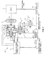
- FIG. 1 is a diagram schematically showing a vehicle with a continuously variable transmission according to an embodiment of the present invention.
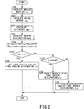
- FIG. 2 is a flow chart for calculating a final angular acceleration of this embodiment.
- FIG. 3 is a flow chart showing a limiter setting control of this embodiment.
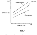
- FIG. 4 is a graph showing a relationship among a primary pulley rotational speed, an engaged state of a torque converter and an upper limiter.
- FIG. 5 is a graph showing a relationship among the primary pulley rotational speed, the engaged state of the torque converter and a lower limiter.
- FIG. 6 is a flow chart showing a method for controlling a primary pulley pressure and a secondary pulley pressure.
- FIG. 1 schematically shows a vehicle with a continuously variable transmission 30 according to this embodiment.
- the continuously variable transmission 30 includes a torque converter 6, a forward/reverse switching mechanism 7, a variator 1 and a transmission controller 12.
- the variator 1 includes a primary pulley 2 and secondary pulley 3 arranged such that V-grooves of the both pulleys are aligned, and a belt 4 is mounted in the V-grooves of these pulleys 2, 3.
- An engine 5 is arranged coaxially with the primary pulley 2, and the torque converter 6 and the forward/reverse switching mechanism 7 are successively disposed from the side of the engine 5 between the engine 5 and the primary pulley 2.
- the torque converter 6 includes a lock-up clutch 6a.
- the torque converter 6 is switched to a lock-up state where the lock-up clutch 6a is completely engaged, a converter state where the lock-up clutch 6a is completely released and a slip state where the lock-up clutch 6a is half-engaged.
- the forward/reverse switching mechanism 7 includes a double-pinion planetary gear set 7a as a main constituent element, a sun gear of the double-pinion planetary gear set 7a is coupled to the engine 5 via the torque converter 6 and a carrier thereof is coupled to the primary pulley 2.
- the forward/reverse switching mechanism 7 further includes a forward clutch 7b for directly coupling the sun gear and the carrier of the double-pinion planetary gear set 7a and a reverse brake 7c for fixing a ring gear.
- Input rotation transmitted from the engine 5 via the torque converter 6 is transmitted to the primary pulley 2 as it is when the forward clutch 7b is engaged, and input rotation transmitted from the engine 5 via the torque converter 6 is transmitted to the primary pulley 2 while being reversed and decelerated when the reverse brake 7c is engaged.
- the rotation of the primary pulley 2 is transmitted to the secondary pulley 3 via the belt 4, and the rotation of the secondary pulley 3 is, thereafter, transmitted to drive wheels 17 via an output shaft 8, a gear set 9 and a differential gear device 10.
- ones of conical plates forming the V-grooves of the primary pulley 2 and the secondary pulley 3 are fixed conical plates 2a, 3a and the other conical plates 2b, 3b are movable conical plates displaceable in an axial direction.
- These movable conical plates 2b, 3b are biased toward the fixed conical plates 2a, 3a by supplying a primary pulley pressure Ppri and a secondary pulley pressure Psec produced using a line pressure as a source pressure to a primary pulley chamber 2c and a secondary pulley chamber 3c, whereby the belt 4 is frictionally engaged with the conical plates to transmit power between the primary pulley 2 and the secondary pulley 3.
- a target speed ratio I(o) is realized by changing the widths of the V-grooves of the both pulleys 2, 3 by a pressure difference between the primary pulley pressure Ppri and the secondary pulley pressure Psec produced in correspondence with the target speed ratio I(o) to continuously change a winding arc diameter of the belt 4 on the pulleys 2, 3.
- the output of the primary pulley pressure Ppri and the secondary pulley pressure Psec is controlled by a transmission control hydraulic circuit 11 together with the output of engaging hydraulic pressures of the forward clutch 7b engaged when a forward drive range is selected and the reverse brake 7c engaged when a reverse drive range is selected.
- the transmission control hydraulic circuit 11 is controlled in response to a signal from the transmission controller 12.
- the transmission controller 12 is composed of a CPU, a ROM, a RAM and the like, and functions of the continuously variable transmission 30 are fulfilled by reading a program stored in the ROM by the CPU.
- the transmission controller 12 calculates an angular velocity ⁇ 0 based on the primary pulley rotational speed Npri calculated by the primary pulley rotation sensor 13.
- the transmission controller 12 calculates the angular velocity ⁇ 0 by detecting a pulse signal given from a rotor 15 integrally rotating with the primary pulley 2 by the primary pulley rotation sensor 13.
- the transmission controller 12 calculates the angular velocity ⁇ 0 by dividing a total time between pulses per unit time by a pulse number per unit time.
- Step S101 the transmission controller 12 calculates a moving average ⁇ AVE of the angular velocity ⁇ 0 using Equation (1).
- ⁇ -n indicates an angular velocity of the primary pulley 2 calculated in the n th previous control before the present one.
- the angular velocity ⁇ 0 calculated this time is stored as an angular velocity ⁇ -1 used in the next control, and the angular velocities ⁇ -1 to ⁇ -5 used to calculate the moving average ⁇ AVE this time are successively updated as angular velocities ⁇ -2 to ⁇ -6 .
- Step S102 the transmission controller 12 calculates a difference tmp1 between the angular velocity ⁇ 0 and the moving average ⁇ AVE calculated this time by Equation (2).
- tmp ⁇ 1 ⁇ 0 - ⁇ AVE
- Step S103 the transmission controller 12 calculates an angular acceleration tmp2 by dividing the difference tmp 1 by a unit time ⁇ t.
- Step S104 the transmission controller 12 calculates an upper limiter ⁇ H and a lower limiter ⁇ L of the angular acceleration by a limiter setting control.
- Step S200 the transmission controller 12 determines an engaged state of the torque converter 6.
- Step S201 the transmission controller 12 calculates the upper limiter ⁇ H from FIG. 4 and the lower limiter ⁇ L from FIG. 5 using the primary pulley rotational speed Npri and the engaged state of the torque converter 6.
- FIG. 4 is a graph showing a relationship among the primary pulley rotational speed Npri, the engaged state of the torque converter 6 and the upper limiter ⁇ H.
- the upper limiter ⁇ H increases as the primary pulley rotational speed Npri increases and as the engaged state of the torque converter 6 changes from the lock-up state to the slip state to the converter state.
- FIG. 5 is a graph showing a relationship among the primary pulley rotational speed Npri, the engaged state of the torque converter 6 and the lower limiter ⁇ L.
- the lower limiter ⁇ L increases in a negative direction as the primary pulley rotational speed Npri increases and as the engaged state of the torque converter 6 changes from the lock-up state to the slip state to the converter state.
- Step S105 the transmission controller 12 compares the angular acceleration tmp2 and the lower limiter ⁇ L. If the angular acceleration tmp2 is not higher than the lower limiter ⁇ L, i.e. if the absolute value of the angular acceleration tmp2 is not smaller than that of the lower limiter ⁇ L, the transmission controller 12 proceeds to Step S106. On the other hand, if the angular acceleration tmp2 is higher than the lower limiter ⁇ L, i.e. if the absolute value of the angular acceleration tmp2 is smaller than that of the lower limiter ⁇ L, the transmission controller 12 proceeds to Step S107.
- Step S106 the transmission controller 12 sets the lower limiter ⁇ L as a final angular acceleration ⁇ .
- Step S107 the transmission controller 12 compares the angular acceleration tmp2 and the upper limiter ⁇ H. If the angular acceleration tmp2 is not lower than the upper limiter ⁇ H, i.e. if the absolute value of the angular acceleration tmp2 is not smaller than that of the upper limiter ⁇ H, the transmission controller 12 proceeds to Step S108. On the other hand, if the angular acceleration tmp2 is lower than the upper limiter ⁇ H, i.e. if the absolute value of the angular acceleration tmp2 is smaller than that of the upper limiter ⁇ H, the transmission controller 12 proceeds to Step S109.
- Step S108 the transmission controller 12 sets the upper limiter ⁇ H as the final angular acceleration ⁇ .
- Step S109 the transmission controller 12 sets the angular acceleration tmp2 as the final angular acceleration ⁇ .
- the angular acceleration tmp2 is more likely to be set as the final angular acceleration ⁇ as the primary pulley rotational speed Npri increases.
- the primary pulley rotation sensor 13 detects fewer pulses per unit time, whereby calculation accuracy of the primary pulley rotational speed Npri decreases. That is, as the primary pulley rotational speed Npri increases, calculation accuracy of the primary pulley rotational speed Npri increases and calculation accuracy of the angular acceleration tmp2 calculated in Step S103 also increases.
- Step S201 as the primary pulley rotational speed Npri increases, the absolute values of the upper limiter ⁇ H and the lower limiter ⁇ L increase. As a result, as the primary pulley rotational speed Npri increases, the angular acceleration tmp2 is more likely to be set as the final angular acceleration ⁇ .
- the absolute values of the upper limiter ⁇ H and the lower limiter ⁇ L increase and the angular acceleration tpm2 is more likely to be set as the final angular acceleration ⁇ .
- the torque converter 6 can absorb influences caused by disturbance and the like and calculation accuracy of the angular acceleration tmp2 increases.
- the angular acceleration tmp2 is more likely to be set as the final angular acceleration ⁇ .
- Step S300 the transmission controller 12 calculates an engine torque Te from the accelerator pedal opening APO and the engine rotational speed.
- Step S301 the transmission controller 12 calculates an input torque Tin to be input to the variator 1 using the engine torque Te and the final angular acceleration ⁇ by Equation (3).
- T in Te - I ⁇ ⁇ ⁇ ⁇
- Equation (3) "I” denotes a moment of inertia in the torque converter 6 and the forward/reverse switching mechanism 7.
- the moment of inertia “I” increases as the engaged state of the torque converter 6 changes from the converter state to the slip state to the lock-up state. This is because the engine 5 becomes a load when viewed from the primary pulley 2 and the load increases as the engaged state of the torque converter 6 changes to the lock-up state. Further, the moment of inertia "I” increases as the number of rotational elements of the forward/reverse switching mechanism 7 increases.
- Step S302 the transmission controller 12 calculates the target speed ratio I(o).
- the transmission controller 12 calculates a target input rotational speed based on a shift map set in advance using a vehicle speed TVO obtained from the secondary pulley rotational speed Nsec and the accelerator pedal opening APO, and calculates a theoretical speed ratio Ip corresponding to a driving condition (vehicle TVO and accelerator pedal opening APO) by dividing the target input rotational speed by the secondary pulley rotational speed Nsec.
- the target speed ratio I(o) is calculated by multiplying a disturbance-compensated theoretical speed ratio Ip by a first-order lag filter ⁇ 1/(Tm ⁇ s+1) ⁇ taking a response delay by hardware into consideration.
- Step S303 the transmission controller 12 calculates a target primary pulley pressure Ppri(o) and a target secondary pulley pressure Psec(o) based on the input torque Tin and the target speed ratio I(o).
- Step S304 the transmission controller 12 controls the primary pulley pressure Ppri and the secondary pulley pressure Psec by supplying or discharging oil to or from the primary pulley chamber 2c and the secondary pulley chamber 3c based on the target primary pulley pressure Ppri(o) and the target secondary pulley pressure Psec(o).
- the primary pulley pressure Ppri and the secondary pulley pressure Psec are controlled to realize a shift.
- the upper limiter ⁇ H and the lower limiter ⁇ L are so calculated that the absolute values thereof increase as the engaged state of the torque converter 6 changes from the lock-up state to the slip state to the converter state. Then, the smaller one of the absolute value of the angular acceleration tmp2 and that of the upper limiter ⁇ H or the lower limiter ⁇ L is set as the final angular acceleration ⁇ .
- the primary pulley pressure and the secondary pulley pressure are controlled based on a change in the engine torque without using this embodiment, the primary pulley pressure and the secondary pulley pressure may be increased or decreased by an inertia torque in the torque converter and the like although a torque variation caused by a change in engine torque does not occur in the variator.
- fuel economy may be deteriorated by excessive hydraulic pressure supply relative to a necessary pressure or belt slippage may occur due to insufficient hydraulic pressure supply.
- the primary pulley pressure Ppri and the secondary pulley pressure Psec can be accurately controlled without being affected by an inertia torque and the like in the torque converter 6 and the like by controlling the primary pulley pressure Ppri and the secondary pulley pressure Psec based on the input torque Tin to the variator 1.
- the angular acceleration ⁇ can be accurately calculated, the input torque Tin to be input to the variator 1 can be accurately calculated and the primary pulley pressure Ppri and the secondary pulley pressure Psec can be accurately controlled.
- the angular acceleration tmp2 is set as the final angular acceleration ⁇ if calculation accuracy of the primary pulley rotational speed Npri is high. In this way, it is possible to improve accuracy of the final angular acceleration ⁇ , improve fuel economy and suppress the occurrence of belt slippage.
- the angular acceleration tmp2 may be set as the final angular acceleration ⁇ without setting the lower limit ⁇ L if the angular acceleration tmp2 has a negative value. This prevents the lower limiter ⁇ L from being set as the final angular acceleration ⁇ L if the angular acceleration tmp2 decreases in a negative direction, i.e. if a torque transmitted to the variator 1 decreases.
- the angular acceleration tmp2 is calculated based on the primary pulley rotation sensor 13 in this embodiment, the angular acceleration may be calculated using, for example, a turbine rotation sensor and a vehicle speed sensor arranged closer to the drive wheels 17 than the torque converter 6 without being limited to this.
- the belt 4 is described as a power transmission member wound around the primary pulley 2 and the secondary pulley 3 in this embodiment, the power transmission member may be a chain formed by coupling a plurality of links by pins without being limited to this.
- the engine 5 is used as a drive source, a motor may be used.
Landscapes
- Engineering & Computer Science (AREA)
- General Engineering & Computer Science (AREA)
- Mechanical Engineering (AREA)
- Control Of Transmission Device (AREA)
Abstract
Description
- The present invention relates to a controller for a continuously variable transmission and a control method thereof.
-
JP2005-344860A - The upper-limit threshold value and the lower-limit threshold value of the above invention are set with a margin so that the output correction value is used in the case of false detection caused by a sensor error or disturbance.
- The margin is preferably set such that an output value of the sensor becomes the final rotational speed in a range where detection accuracy of the sensor is high and the output correction value becomes the final rotational speed in a range where the detection accuracy of the sensor is low.
- Here, when there is a rotational speed difference between an input rotational speed and an output rotational speed (e.g. converter state) in a torque converter, influences caused by disturbance and the like are absorbed by the torque converter, wherefore the detection accuracy by the sensor increases. On the other hand, when there is no rotational speed difference between the input rotational speed and the output rotational speed (lock-up state), influences caused by disturbance and the like cannot be absorbed by the torque converter, wherefore the detection accuracy by the sensor decreases.
- That is, it is preferable that the output value of the sensor becomes the final rotational speed when there is a rotational speed difference in the torque converter and the output correction value becomes the final rotational speed when there is no rotational speed difference.
- However, in the above invention, the upper limit value and the like are set without considering the states of the torque converter (converter state, lock-up state and the like). Thus, if the margin is set to be excessively large, the output value of the sensor may be set as the final rotational speed despite low detection accuracy of the sensor due to an influence such as an error or disturbance when the torque converter is in the lock-up state. On the other hand, if the margin is set to be excessively small, the output correction value may be set as the final rotational speed despite high detection accuracy of the sensor when the torque converter is in the converter state. If the rotational speed with low accuracy is set as the final rotational speed and a hydraulic pressure of the transmission is controlled based on the rotational speed with low accuracy in this way, there is a problem that fuel economy is deteriorated by excessive supply of the hydraulic pressure or belt slippage occurs due to insufficient supply of the hydraulic pressure.
- The present invention was developed to solve such a problem and aims to improve fuel economy and suppress belt slippage by calculating a final rotational speed in conformity with a state of a torque converter and controlling a hydraulic pressure of a transmission based on a rotational speed with high accuracy.
- One aspect of the present invention is directed to a controller for controlling a continuously variable transmission including a variator with a primary pulley at an input side for changing a groove width by a hydraulic pressure, a secondary pulley at an output side for changing a groove width by a hydraulic pressure and a power transmission member mounted between the primary pulley and the secondary pulley, and a torque converter arranged between a drive source and the variator. The controller includes a rotational speed detecting unit that detects the rotational speed of a rotor located closer to drive wheels than the torque converter; a rotational speed change amount calculating unit that calculates a change amount in the rotational speed per unit time; a limit setting unit that sets a higher absolute value of a limiter for the change amount as a rotational speed difference between an input shaft and an output shaft of the torque converter increases; a final change amount setting unit that sets the smaller one of the absolute value of the change amount and that of the limiter as a final change amount; and a hydraulic control unit that controls a hydraulic pressure to be supplied to the variator based on the final change amount.
- Another aspect of the present invention is directed to a control method for controlling a continuously variable transmission including a variator with a primary pulley at an input side for changing a groove width by a hydraulic pressure, a secondary pulley at an output side for changing a groove width by a hydraulic pressure and a power transmission member mounted between the primary pulley and the secondary pulley, and a torque converter arranged between a drive source and the variator. The control method includes detecting the rotational speed of a rotor located closer to drive wheels than the torque converter; calculating a change amount in the rotational speed per unit time; setting a higher absolute value of a limiter for the change amount as a rotational speed difference between an input shaft and an output shaft of the torque converter increases; setting the smaller one of the absolute value of the change amount and that of the limiter as a final change amount; and controlling a hydraulic pressure to be supplied to the variator based on the final change amount.
- According to these aspects, it is possible to improve fuel economy and suppress belt slippage since the limiter for the change amount is set according to the state of the torque converter and the hydraulic pressure to be supplied to the variator is controlled using the final change amount with high accuracy.
-
FIG. 1 is a diagram schematically showing a vehicle with a continuously variable transmission according to an embodiment of the present invention. -
FIG. 2 is a flow chart for calculating a final angular acceleration of this embodiment. -
FIG. 3 is a flow chart showing a limiter setting control of this embodiment. -
FIG. 4 is a graph showing a relationship among a primary pulley rotational speed, an engaged state of a torque converter and an upper limiter. -
FIG. 5 is a graph showing a relationship among the primary pulley rotational speed, the engaged state of the torque converter and a lower limiter. -
FIG. 6 is a flow chart showing a method for controlling a primary pulley pressure and a secondary pulley pressure. - Hereinafter, an embodiment of the present invention is described in detail based on the drawings.
-
FIG. 1 schematically shows a vehicle with a continuouslyvariable transmission 30 according to this embodiment. The continuouslyvariable transmission 30 includes atorque converter 6, a forward/reverse switching mechanism 7, avariator 1 and atransmission controller 12. - The
variator 1 includes aprimary pulley 2 and secondary pulley 3 arranged such that V-grooves of the both pulleys are aligned, and a belt 4 is mounted in the V-grooves of thesepulleys 2, 3. - An
engine 5 is arranged coaxially with theprimary pulley 2, and thetorque converter 6 and the forward/reverse switching mechanism 7 are successively disposed from the side of theengine 5 between theengine 5 and theprimary pulley 2. - The
torque converter 6 includes a lock-up clutch 6a. Thetorque converter 6 is switched to a lock-up state where the lock-up clutch 6a is completely engaged, a converter state where the lock-up clutch 6a is completely released and a slip state where the lock-up clutch 6a is half-engaged. - The forward/
reverse switching mechanism 7 includes a double-pinionplanetary gear set 7a as a main constituent element, a sun gear of the double-pinionplanetary gear set 7a is coupled to theengine 5 via thetorque converter 6 and a carrier thereof is coupled to theprimary pulley 2. The forward/reverse switching mechanism 7 further includes aforward clutch 7b for directly coupling the sun gear and the carrier of the double-pinion planetary gear set 7a and a reverse brake 7c for fixing a ring gear. Input rotation transmitted from theengine 5 via thetorque converter 6 is transmitted to theprimary pulley 2 as it is when theforward clutch 7b is engaged, and input rotation transmitted from theengine 5 via thetorque converter 6 is transmitted to theprimary pulley 2 while being reversed and decelerated when the reverse brake 7c is engaged. - The rotation of the
primary pulley 2 is transmitted to the secondary pulley 3 via the belt 4, and the rotation of the secondary pulley 3 is, thereafter, transmitted to drivewheels 17 via an output shaft 8, agear set 9 and adifferential gear device 10. - To make a rotation transmission ratio (speed ratio) between the
primary pulley 2 and the secondary pulley 3 changeable during the above power transmission, ones of conical plates forming the V-grooves of theprimary pulley 2 and the secondary pulley 3 are fixedconical plates 2a, 3a and the otherconical plates conical plates conical plates 2a, 3a by supplying a primary pulley pressure Ppri and a secondary pulley pressure Psec produced using a line pressure as a source pressure to aprimary pulley chamber 2c and a secondary pulley chamber 3c, whereby the belt 4 is frictionally engaged with the conical plates to transmit power between theprimary pulley 2 and the secondary pulley 3. - In shifting the transmission, a target speed ratio I(o) is realized by changing the widths of the V-grooves of the both
pulleys 2, 3 by a pressure difference between the primary pulley pressure Ppri and the secondary pulley pressure Psec produced in correspondence with the target speed ratio I(o) to continuously change a winding arc diameter of the belt 4 on thepulleys 2, 3. - The output of the primary pulley pressure Ppri and the secondary pulley pressure Psec is controlled by a transmission control
hydraulic circuit 11 together with the output of engaging hydraulic pressures of theforward clutch 7b engaged when a forward drive range is selected and the reverse brake 7c engaged when a reverse drive range is selected. The transmission controlhydraulic circuit 11 is controlled in response to a signal from thetransmission controller 12. - To the
transmission controller 12 are input a signal from a primarypulley rotation sensor 13 for detecting a primary pulley rotational speed Npri, a signal from a secondarypulley rotation sensor 14 for detecting a secondary pulley rotational speed Nsec, a signal from an acceleratorpedal opening sensor 16 for detecting an acceleration pedal opening APO, an engine rotational speed and a fuel injection time from anengine controller 19 for controlling theengine 5, and the like. - The
transmission controller 12 is composed of a CPU, a ROM, a RAM and the like, and functions of the continuouslyvariable transmission 30 are fulfilled by reading a program stored in the ROM by the CPU. - Next, a control of this embodiment for calculating a final angular acceleration is described using a flow chart of
FIG. 2 . The control described below is executed at every predetermined time interval, e.g. every 1/100 sec. - In Sep S100, the
transmission controller 12 calculates an angular velocity ω0 based on the primary pulley rotational speed Npri calculated by the primarypulley rotation sensor 13. Thetransmission controller 12 calculates the angular velocity ω0 by detecting a pulse signal given from arotor 15 integrally rotating with theprimary pulley 2 by the primarypulley rotation sensor 13. In this embodiment, thetransmission controller 12 calculates the angular velocity ω0 by dividing a total time between pulses per unit time by a pulse number per unit time. - In Step S101, the
transmission controller 12 calculates a moving average ωAVE of the angular velocity ω0 using Equation (1).
- ω-n indicates an angular velocity of the
primary pulley 2 calculated in the nth previous control before the present one. Here, the moving average ωAVE is calculated using five angular velocities (n = 5) obtained in the controls immediately before the present control. That is, the moving average ωAVE is a moving average from an angular velocity ω-5 calculated in the fifth previous control from the present one to an angular velocity ω-1 calculated in the last control. - Note that it is also possible to improve detection accuracy using a low-pass filter, but the influence of an abnormal value becomes large and an error becomes large when there is an outstandingly different abnormal value in the case of using the low-pass filter. Further, a response is delayed by a time constant of the filter.
- In this embodiment, it is possible to reduce a process load and improve detection accuracy and responsiveness by using the moving average.
- The angular velocity ω0 calculated this time is stored as an angular velocity ω-1 used in the next control, and the angular velocities ω-1 to ω-5 used to calculate the moving average ωAVE this time are successively updated as angular velocities ω-2 to ω-6.
- In Step S102, the
transmission controller 12 calculates a difference tmp1 between the angular velocity ω0 and the moving average ωAVE calculated this time by Equation (2).
- In Step S103, the
transmission controller 12 calculates an angular acceleration tmp2 by dividing thedifference tmp 1 by a unit time Δt. - In Step S104, the
transmission controller 12 calculates an upper limiter ΔωH and a lower limiter ΔωL of the angular acceleration by a limiter setting control. - Here, the limiter setting control is described using a flow chart of
FIG. 3 . - In Step S200, the
transmission controller 12 determines an engaged state of thetorque converter 6. - In Step S201, the
transmission controller 12 calculates the upper limiter ΔωH fromFIG. 4 and the lower limiter ΔωL fromFIG. 5 using the primary pulley rotational speed Npri and the engaged state of thetorque converter 6. -
FIG. 4 is a graph showing a relationship among the primary pulley rotational speed Npri, the engaged state of thetorque converter 6 and the upper limiter ΔωH. The upper limiter ΔωH increases as the primary pulley rotational speed Npri increases and as the engaged state of thetorque converter 6 changes from the lock-up state to the slip state to the converter state. -
FIG. 5 is a graph showing a relationship among the primary pulley rotational speed Npri, the engaged state of thetorque converter 6 and the lower limiter ΔωL. The lower limiter ΔωL increases in a negative direction as the primary pulley rotational speed Npri increases and as the engaged state of thetorque converter 6 changes from the lock-up state to the slip state to the converter state. - Referring back to
FIG. 2 , in Step S105, thetransmission controller 12 compares the angular acceleration tmp2 and the lower limiter ΔωL. If the angular acceleration tmp2 is not higher than the lower limiter ΔωL, i.e. if the absolute value of the angular acceleration tmp2 is not smaller than that of the lower limiter ΔωL, thetransmission controller 12 proceeds to Step S106. On the other hand, if the angular acceleration tmp2 is higher than the lower limiter ΔωL, i.e. if the absolute value of the angular acceleration tmp2 is smaller than that of the lower limiter ΔωL, thetransmission controller 12 proceeds to Step S107. - In Step S106, the
transmission controller 12 sets the lower limiter ΔωL as a final angular acceleration Δω. - In Step S107, the
transmission controller 12 compares the angular acceleration tmp2 and the upper limiter ΔωH. If the angular acceleration tmp2 is not lower than the upper limiter ΔωH, i.e. if the absolute value of the angular acceleration tmp2 is not smaller than that of the upper limiter ΔωH, thetransmission controller 12 proceeds to Step S108. On the other hand, if the angular acceleration tmp2 is lower than the upper limiter ΔωH, i.e. if the absolute value of the angular acceleration tmp2 is smaller than that of the upper limiter ΔωH, thetransmission controller 12 proceeds to Step S109. - In Step S108, the
transmission controller 12 sets the upper limiter ΔωH as the final angular acceleration Δω. - In Step S109, the
transmission controller 12 sets the angular acceleration tmp2 as the final angular acceleration Δω. - In the above control, the angular acceleration tmp2 is more likely to be set as the final angular acceleration Δω as the primary pulley rotational speed Npri increases. When the primary pulley rotational speed Npri decreases, the primary
pulley rotation sensor 13 detects fewer pulses per unit time, whereby calculation accuracy of the primary pulley rotational speed Npri decreases. That is, as the primary pulley rotational speed Npri increases, calculation accuracy of the primary pulley rotational speed Npri increases and calculation accuracy of the angular acceleration tmp2 calculated in Step S103 also increases. Thus, in Step S201, as the primary pulley rotational speed Npri increases, the absolute values of the upper limiter ΔωH and the lower limiter ΔωL increase. As a result, as the primary pulley rotational speed Npri increases, the angular acceleration tmp2 is more likely to be set as the final angular acceleration Δω. - Further, as the engaged state of the
torque converter 6 changes to the converter state, the absolute values of the upper limiter ΔωH and the lower limiter ΔωL increase and the angular acceleration tpm2 is more likely to be set as the final angular acceleration Δω. As the engaged state of thetorque converter 6 changes from the lockup state to the slip state to the converter state, thetorque converter 6 can absorb influences caused by disturbance and the like and calculation accuracy of the angular acceleration tmp2 increases. Thus, as the engaged state of the torque converter changes to the converter state, the angular acceleration tmp2 is more likely to be set as the final angular acceleration Δω. - Next, a method for controlling the primary pulley pressure Ppri and the secondary pulley pressure Psec using the final angular acceleration Δω set using
FIG. 2 is described using a flow chart ofFIG. 6 . - In Step S300, the
transmission controller 12 calculates an engine torque Te from the accelerator pedal opening APO and the engine rotational speed. - In Step S301, the
transmission controller 12 calculates an input torque Tin to be input to thevariator 1 using the engine torque Te and the final angular acceleration Δω by Equation (3).
- In Equation (3), "I" denotes a moment of inertia in the
torque converter 6 and the forward/reverse switching mechanism 7. The moment of inertia "I" increases as the engaged state of thetorque converter 6 changes from the converter state to the slip state to the lock-up state. This is because theengine 5 becomes a load when viewed from theprimary pulley 2 and the load increases as the engaged state of thetorque converter 6 changes to the lock-up state. Further, the moment of inertia "I" increases as the number of rotational elements of the forward/reverse switching mechanism 7 increases. - In Step S302, the
transmission controller 12 calculates the target speed ratio I(o). Thetransmission controller 12 calculates a target input rotational speed based on a shift map set in advance using a vehicle speed TVO obtained from the secondary pulley rotational speed Nsec and the accelerator pedal opening APO, and calculates a theoretical speed ratio Ip corresponding to a driving condition (vehicle TVO and accelerator pedal opening APO) by dividing the target input rotational speed by the secondary pulley rotational speed Nsec. - Subsequently, after an actual speed ratio ip is calculated by dividing the primary pulley rotational speed Npri by the secondary pulley rotational speed Nsec and a deviation between the theoretical speed ratio Ip and the actual speed ratio ip is calculated, the target speed ratio I(o) is calculated by multiplying a disturbance-compensated theoretical speed ratio Ip by a first-order lag filter {1/(Tm·s+1)} taking a response delay by hardware into consideration.
- In Step S303, the
transmission controller 12 calculates a target primary pulley pressure Ppri(o) and a target secondary pulley pressure Psec(o) based on the input torque Tin and the target speed ratio I(o). - In Step S304, the
transmission controller 12 controls the primary pulley pressure Ppri and the secondary pulley pressure Psec by supplying or discharging oil to or from theprimary pulley chamber 2c and the secondary pulley chamber 3c based on the target primary pulley pressure Ppri(o) and the target secondary pulley pressure Psec(o). - By the above control, the primary pulley pressure Ppri and the secondary pulley pressure Psec are controlled to realize a shift.
- Effects of the embodiment of the present invention are described.
- The upper limiter ΔωH and the lower limiter ΔωL are so calculated that the absolute values thereof increase as the engaged state of the
torque converter 6 changes from the lock-up state to the slip state to the converter state. Then, the smaller one of the absolute value of the angular acceleration tmp2 and that of the upper limiter ΔωH or the lower limiter ΔωL is set as the final angular acceleration Δω. - When the
torque converter 6 is in the slip state or the converter state, influences caused by disturbance and the like can be absorbed by thetorque converter 6. Thus, accuracy of the angular acceleration tmp2 calculated based on the primary pulley rotational speed Npri detected by the primarypulley rotation sensor 13 is high. In this case, by setting the angular acceleration tmp2 as the final angular acceleration Δω, it is possible to accurately control the primary pulley pressure Ppri and the secondary pulley pressure Psec, improve fuel economy and suppress belt slippage. - Further, when the
torque converter 6 is in the lock-up state, influences caused by disturbance and the like reach the primarypulley rotation sensor 13 and accuracy of the angular acceleration tmp2 calculated based on the primary pulley rotational speed Npri detected by the primarypulley rotation sensor 13 is low. In this case, by setting the upper limiter ΔωH or the lower limiter ΔωL as the final angular acceleration Δω, it is possible to accurately control the primary pulley pressure Ppri and the secondary pulley pressure Psec by suppressing influences caused by disturbance and the like, improve fuel economy and suppress belt slippage. - If the primary pulley pressure and the secondary pulley pressure are controlled based on a change in the engine torque without using this embodiment, the primary pulley pressure and the secondary pulley pressure may be increased or decreased by an inertia torque in the torque converter and the like although a torque variation caused by a change in engine torque does not occur in the variator. Thus, fuel economy may be deteriorated by excessive hydraulic pressure supply relative to a necessary pressure or belt slippage may occur due to insufficient hydraulic pressure supply.
- On the contrary, in this embodiment, the primary pulley pressure Ppri and the secondary pulley pressure Psec can be accurately controlled without being affected by an inertia torque and the like in the
torque converter 6 and the like by controlling the primary pulley pressure Ppri and the secondary pulley pressure Psec based on the input torque Tin to thevariator 1. Thus, it is possible to improve fuel economy and suppress the occurrence of belt slippage. Further, since the angular acceleration Δω can be accurately calculated, the input torque Tin to be input to thevariator 1 can be accurately calculated and the primary pulley pressure Ppri and the secondary pulley pressure Psec can be accurately controlled. Thus, it is possible to improve fuel economy and suppress the occurrence of belt slippage. - By increasing the absolute values of the upper limiter ΔωH and the lower limiter ΔωL as the primary pulley rotational speed Npri increases, the angular acceleration tmp2 is set as the final angular acceleration Δω if calculation accuracy of the primary pulley rotational speed Npri is high. In this way, it is possible to improve accuracy of the final angular acceleration Δω, improve fuel economy and suppress the occurrence of belt slippage.
- The present invention is not limited to the above embodiment and it goes without saying that various changes and improvements that can be made within the scope of the technical concept of the present invention are included.
- Although the lower limiter ΔωL is set and the angular acceleration is limited also when the angular acceleration tmp2 has a negative value in the above embodiment, the angular acceleration tmp2 may be set as the final angular acceleration Δω without setting the lower limit ΔωL if the angular acceleration tmp2 has a negative value. This prevents the lower limiter ΔωL from being set as the final angular acceleration ΔωL if the angular acceleration tmp2 decreases in a negative direction, i.e. if a torque transmitted to the
variator 1 decreases. Thus, there is no likelihood that the primary pulley pressure Ppri or the secondary pulley pressure Psec is controlled to a hydraulic pressure lower than a hydraulic pressure necessary to prevent belt slippage in thevariator 1. Therefore, it can be suppressed that belt slippage occurs at the primary pulley or the secondary pulley due to insufficient hydraulic pressure. - Further, although the angular acceleration tmp2 is calculated based on the primary
pulley rotation sensor 13 in this embodiment, the angular acceleration may be calculated using, for example, a turbine rotation sensor and a vehicle speed sensor arranged closer to thedrive wheels 17 than thetorque converter 6 without being limited to this. - Further, although the belt 4 is described as a power transmission member wound around the
primary pulley 2 and the secondary pulley 3 in this embodiment, the power transmission member may be a chain formed by coupling a plurality of links by pins without being limited to this. - Furthermore, although the
engine 5 is used as a drive source, a motor may be used. - This application claims priority from Japanese Patent Application No.
2011-63899, filed March 23, 2011
Claims (8)
- A controller (12) for controlling a continuously variable transmission (30) including a variator (1) with a primary pulley (2) at an input side for changing a groove width by a hydraulic pressure, a secondary pulley (3) at an output side for changing a groove width by a hydraulic pressure and a power transmission member (4) mounted between the primary pulley (2) and the secondary pulley (3), and a torque converter (6) arranged between a drive source (5) and the variator (1), comprising:rotational speed detecting means (13) adapted to detect the rotational speed of a rotor (15) located closer to drive wheels (17) than the torque converter (6);rotational speed change amount calculating means (12) adapted to calculate a change amount in the rotational speed per unit time;limit setting means (12) adapted to set a higher absolute value of a limiter for the change amount as a rotational speed difference between an input shaft and an output shaft of the torque converter (6) increases;final change amount setting means (12) adapted to set the smaller one of the absolute value of the change amount and that of the limiter as a final change amount; andhydraulic control means (12) adapted to control a hydraulic pressure to be supplied to the variator (1) based on the final change amount.
- The controller (12) according to claim 1, further comprising input torque calculating means (12) adapted to calculate an input torque to be input to the variator (1) based on the final change amount, wherein:the hydraulic control means (12) controls the hydraulic pressure to be supplied to the variator (1) based on the input torque.
- The controller (12) according to claim 1 or 2, wherein:the rotational speed detecting means (13) detects the rotational speed based on a pulse signal given by the rotation of the rotor (15); andthe limit setting means (12) increases the absolute value of the limiter as the rotational speed of the rotor (15) increases.
- The controller (12) according to any one of claims 1 to 3, wherein the final change amount setting means (12) sets the change amount as the final change amount if the change amount is negative.
- A control method for controlling a continuously variable transmission (30) including a variator (1) with a primary pulley (2) at an input side for changing a groove width by a hydraulic pressure, a secondary pulley (3) at an output side for changing a groove width by a hydraulic pressure and a power transmission member (4) mounted between the primary pulley (2) and the secondary pulley (3), and a torque converter (6) arranged between a drive source (5) and the variator (1), comprising:detecting the rotational speed of a rotor (15) located closer to drive wheels (17) than the torque converter (6);calculating a change amount in the rotational speed per unit time;setting a higher absolute value of a limiter for the change amount as a rotational speed difference between an input shaft and an output shaft of the torque converter (6) increases;setting the smaller one of the absolute value of the change amount and that of the limiter as a final change amount; andcontrolling a hydraulic pressure to be supplied to the variator (1) based on the final change amount.
- The control method according to claim 5, further comprising calculating an input torque to be input to the variator (1) based on the final change amount, wherein:the hydraulic pressure to be supplied to the variator (1) is controlled based on the input torque.
- The control method according to claim 5 or 6, wherein:the rotational speed is detected based on a pulse signal given by the rotation of the rotor (15); andthe absolute value of the limiter increases as the rotational speed of the rotor (15) increases.
- The control method according to any one of claims 5 to 7, wherein the change amount is set as the final change amount if the change amount is negative.
Applications Claiming Priority (1)
| Application Number | Priority Date | Filing Date | Title |
|---|---|---|---|
| JP2011063899A JP5309174B2 (en) | 2011-03-23 | 2011-03-23 | Control device for continuously variable transmission |
Publications (3)
| Publication Number | Publication Date |
|---|---|
| EP2503196A2 true EP2503196A2 (en) | 2012-09-26 |
| EP2503196A3 EP2503196A3 (en) | 2012-12-05 |
| EP2503196B1 EP2503196B1 (en) | 2014-01-15 |
Family
ID=45654847
Family Applications (1)
| Application Number | Title | Priority Date | Filing Date |
|---|---|---|---|
| EP12000720.8A Not-in-force EP2503196B1 (en) | 2011-03-23 | 2012-02-03 | Controller for continuously variable transmission and control method thereof |
Country Status (5)
| Country | Link |
|---|---|
| US (1) | US8560187B2 (en) |
| EP (1) | EP2503196B1 (en) |
| JP (1) | JP5309174B2 (en) |
| KR (1) | KR101312162B1 (en) |
| CN (1) | CN102691789B (en) |
Families Citing this family (13)
| Publication number | Priority date | Publication date | Assignee | Title |
|---|---|---|---|---|
| JP2001104636A (en) | 1999-10-04 | 2001-04-17 | Shinsedai Kk | Cenesthesic ball game device |
| CN105683626B (en) * | 2013-10-18 | 2017-09-01 | 本田技研工业株式会社 | Speed-change control device and shifting control method |
| DE102014201131A1 (en) * | 2014-01-22 | 2015-07-23 | Zf Friedrichshafen Ag | Transmission device with a hydraulic system |
| US10077837B2 (en) * | 2014-03-10 | 2018-09-18 | Aisin Aw Co., Ltd. | Control device and control method for continuously variable transmission |
| JP6070623B2 (en) * | 2014-04-25 | 2017-02-01 | トヨタ自動車株式会社 | Vehicle control device |
| CN106574714B (en) * | 2014-07-30 | 2018-10-02 | 加特可株式会社 | The control device of contiuously variable transmission |
| WO2016082132A1 (en) * | 2014-11-26 | 2016-06-02 | GM Global Technology Operations LLC | Mode transition control in a cvt with fixed gear functionality |
| US10507833B2 (en) * | 2015-03-23 | 2019-12-17 | Jatco Ltd | Vehicle control device and method for controlling the same |
| US9765884B2 (en) * | 2015-11-09 | 2017-09-19 | GM Global Technology Operations LLC | Method and apparatus to control a continuously variable transmission |
| US9890857B2 (en) * | 2015-12-22 | 2018-02-13 | GM Global Technology Operations LLC | CVT and method for mitigating variator gross slip of the same |
| CN109695713B (en) * | 2017-10-20 | 2020-06-05 | 上海汽车集团股份有限公司 | Steel belt slippage simulation method and device for continuously variable transmission |
| JP2022044402A (en) * | 2020-09-07 | 2022-03-17 | 株式会社アイシン | Power transmission device |
| JP7241124B2 (en) * | 2021-04-21 | 2023-03-16 | 本田技研工業株式会社 | Control device and control method for continuously variable transmission for vehicle |
Citations (2)
| Publication number | Priority date | Publication date | Assignee | Title |
|---|---|---|---|---|
| JP2005344860A (en) | 2004-06-03 | 2005-12-15 | Toyota Motor Corp | Slip detection device for continuously variable transmission |
| JP2011063899A (en) | 2009-09-16 | 2011-03-31 | Daio Paper Corp | Coated paper |
Family Cites Families (12)
| Publication number | Priority date | Publication date | Assignee | Title |
|---|---|---|---|---|
| JP3187865B2 (en) * | 1991-05-31 | 2001-07-16 | 富士重工業株式会社 | Shift control device for continuously variable transmission with lock-up torque converter |
| JPH09105454A (en) * | 1995-10-12 | 1997-04-22 | Jatco Corp | Control method and control device for automatic transmission |
| JP3527391B2 (en) * | 1997-07-30 | 2004-05-17 | 日産自動車株式会社 | Shift control method for continuously variable transmission for vehicle |
| JP2001090825A (en) * | 1999-09-24 | 2001-04-03 | Mitsubishi Motors Corp | Transmission input torque calculation device |
| JP4126152B2 (en) * | 2000-09-26 | 2008-07-30 | ジヤトコ株式会社 | Shift control device for continuously variable transmission |
| JP4020604B2 (en) * | 2001-08-01 | 2007-12-12 | トヨタ自動車株式会社 | Shift control device for automatic transmission for vehicle |
| US6740005B2 (en) * | 2001-08-01 | 2004-05-25 | Toyota Jidosha Kabushiki Kaisha | Shift control apparatus of automatic transmission of motor vehicle |
| JP3597808B2 (en) * | 2001-09-28 | 2004-12-08 | トヨタ自動車株式会社 | Slip detector for continuously variable transmission |
| JP4072200B2 (en) * | 2002-09-30 | 2008-04-09 | ジヤトコ株式会社 | Control device for belt type continuously variable transmission |
| JP4611661B2 (en) * | 2004-04-27 | 2011-01-12 | 富士重工業株式会社 | Control method and control apparatus for automatic transmission |
| JP4762875B2 (en) * | 2006-12-15 | 2011-08-31 | ジヤトコ株式会社 | Shift control device for belt type continuously variable transmission |
| JP4907681B2 (en) * | 2009-03-06 | 2012-04-04 | 日産自動車株式会社 | Control device for automatic transmission |
-
2011
- 2011-03-23 JP JP2011063899A patent/JP5309174B2/en not_active Expired - Fee Related
-
2012
- 2012-02-03 EP EP12000720.8A patent/EP2503196B1/en not_active Not-in-force
- 2012-02-13 US US13/371,871 patent/US8560187B2/en not_active Expired - Fee Related
- 2012-03-13 CN CN201210064224.XA patent/CN102691789B/en not_active Expired - Fee Related
- 2012-03-22 KR KR1020120029370A patent/KR101312162B1/en not_active Expired - Fee Related
Patent Citations (2)
| Publication number | Priority date | Publication date | Assignee | Title |
|---|---|---|---|---|
| JP2005344860A (en) | 2004-06-03 | 2005-12-15 | Toyota Motor Corp | Slip detection device for continuously variable transmission |
| JP2011063899A (en) | 2009-09-16 | 2011-03-31 | Daio Paper Corp | Coated paper |
Also Published As
| Publication number | Publication date |
|---|---|
| US8560187B2 (en) | 2013-10-15 |
| KR101312162B1 (en) | 2013-09-26 |
| EP2503196A3 (en) | 2012-12-05 |
| CN102691789B (en) | 2015-01-21 |
| JP2012197914A (en) | 2012-10-18 |
| US20120245807A1 (en) | 2012-09-27 |
| JP5309174B2 (en) | 2013-10-09 |
| CN102691789A (en) | 2012-09-26 |
| KR20120109363A (en) | 2012-10-08 |
| EP2503196B1 (en) | 2014-01-15 |
Similar Documents
| Publication | Publication Date | Title |
|---|---|---|
| EP2503196B1 (en) | Controller for continuously variable transmission and control method thereof | |
| US8414453B2 (en) | Continuously variable transmission and control method thereof | |
| US9568098B2 (en) | Controller for vehicle transmission | |
| US10851890B2 (en) | Control apparatus for vehicle drive-force transmitting apparatus | |
| US10683931B2 (en) | Control apparatus for vehicle drive-force transmitting apparatus | |
| US10377367B2 (en) | Control device for hybrid vehicle and control method of the same | |
| KR101584475B1 (en) | Continuously variable transmission and hydraulic pressure control method therefor | |
| CN110118249B (en) | Control device for vehicle power transmission device | |
| US7510501B2 (en) | Hydraulic control system of belt-type continuously variable transmission for vehicle | |
| JP5783055B2 (en) | Transmission abnormality determination device | |
| US10086817B2 (en) | Control device and control method for vehicle | |
| WO2018047559A1 (en) | Continuously variable transmission and continuously variable transmission control method | |
| EP3306144A1 (en) | Control device for continuously variable transmission | |
| US10704686B2 (en) | Control apparatus for vehicle drive-force transmitting apparatus | |
| JP4474832B2 (en) | Control device for continuously variable transmission | |
| JP7139648B2 (en) | Control device for power transmission device for vehicle | |
| JP2005344860A (en) | Slip detection device for continuously variable transmission | |
| JP4380170B2 (en) | Control device for continuously variable transmission | |
| JP4349099B2 (en) | Control device for continuously variable transmission | |
| EP3315824A1 (en) | Transmission and transmission control method | |
| JP2004324717A (en) | Slip detector for continuously variable transmission | |
| JP2005226815A (en) | Control device for continuously variable transmission | |
| JP2004044759A (en) | Actuator control device |
Legal Events
| Date | Code | Title | Description |
|---|---|---|---|
| PUAI | Public reference made under article 153(3) epc to a published international application that has entered the european phase |
Free format text: ORIGINAL CODE: 0009012 |
|
| AK | Designated contracting states |
Kind code of ref document: A2 Designated state(s): AL AT BE BG CH CY CZ DE DK EE ES FI FR GB GR HR HU IE IS IT LI LT LU LV MC MK MT NL NO PL PT RO RS SE SI SK SM TR |
|
| AX | Request for extension of the european patent |
Extension state: BA ME |
|
| PUAL | Search report despatched |
Free format text: ORIGINAL CODE: 0009013 |
|
| AK | Designated contracting states |
Kind code of ref document: A3 Designated state(s): AL AT BE BG CH CY CZ DE DK EE ES FI FR GB GR HR HU IE IS IT LI LT LU LV MC MK MT NL NO PL PT RO RS SE SI SK SM TR |
|
| AX | Request for extension of the european patent |
Extension state: BA ME |
|
| RIC1 | Information provided on ipc code assigned before grant |
Ipc: F16H 61/70 20060101ALN20121031BHEP Ipc: F16H 61/662 20060101AFI20121031BHEP |
|
| 17P | Request for examination filed |
Effective date: 20130603 |
|
| RBV | Designated contracting states (corrected) |
Designated state(s): AL AT BE BG CH CY CZ DE DK EE ES FI FR GB GR HR HU IE IS IT LI LT LU LV MC MK MT NL NO PL PT RO RS SE SI SK SM TR |
|
| GRAP | Despatch of communication of intention to grant a patent |
Free format text: ORIGINAL CODE: EPIDOSNIGR1 |
|
| RIC1 | Information provided on ipc code assigned before grant |
Ipc: F16H 61/662 20060101AFI20130913BHEP Ipc: F16H 59/46 20060101ALN20130913BHEP Ipc: F16H 61/70 20060101ALN20130913BHEP |
|
| INTG | Intention to grant announced |
Effective date: 20131022 |
|
| GRAS | Grant fee paid |
Free format text: ORIGINAL CODE: EPIDOSNIGR3 |
|
| GRAA | (expected) grant |
Free format text: ORIGINAL CODE: 0009210 |
|
| AK | Designated contracting states |
Kind code of ref document: B1 Designated state(s): AL AT BE BG CH CY CZ DE DK EE ES FI FR GB GR HR HU IE IS IT LI LT LU LV MC MK MT NL NO PL PT RO RS SE SI SK SM TR |
|
| REG | Reference to a national code |
Ref country code: GB Ref legal event code: FG4D Ref country code: CH Ref legal event code: EP |
|
| REG | Reference to a national code |
Ref country code: AT Ref legal event code: REF Ref document number: 649992 Country of ref document: AT Kind code of ref document: T Effective date: 20140215 |
|
| REG | Reference to a national code |
Ref country code: IE Ref legal event code: FG4D |
|
| REG | Reference to a national code |
Ref country code: DE Ref legal event code: R096 Ref document number: 602012000785 Country of ref document: DE Effective date: 20140306 |
|
| REG | Reference to a national code |
Ref country code: DE Ref legal event code: R082 Ref document number: 602012000785 Country of ref document: DE Representative=s name: HOEFER & PARTNER, DE |
|
| RAP2 | Party data changed (patent owner data changed or rights of a patent transferred) |
Owner name: NISSAN MOTOR CO., LTD. Owner name: JATCO LTD |
|
| REG | Reference to a national code |
Ref country code: DE Ref legal event code: R081 Ref document number: 602012000785 Country of ref document: DE Owner name: NISSAN MOTOR CO., LTD., YOKOHAMA-SHI, JP Free format text: FORMER OWNER: JATCO LTD, FUJI, SHIZUOKA, JP Effective date: 20140319 Ref country code: DE Ref legal event code: R081 Ref document number: 602012000785 Country of ref document: DE Owner name: JATCO LTD, FUJI, JP Free format text: FORMER OWNER: JATCO LTD, FUJI, SHIZUOKA, JP Effective date: 20140319 Ref country code: DE Ref legal event code: R082 Ref document number: 602012000785 Country of ref document: DE Representative=s name: HOEFER & PARTNER PATENTANWAELTE MBB, DE Effective date: 20140319 Ref country code: DE Ref legal event code: R081 Ref document number: 602012000785 Country of ref document: DE Owner name: NISSAN MOTOR CO., LTD., JP Free format text: FORMER OWNER: JATCO LTD, FUJI, JP Effective date: 20140319 Ref country code: DE Ref legal event code: R082 Ref document number: 602012000785 Country of ref document: DE Representative=s name: HOEFER & PARTNER, DE Effective date: 20140319 Ref country code: DE Ref legal event code: R081 Ref document number: 602012000785 Country of ref document: DE Owner name: JATCO LTD, JP Free format text: FORMER OWNER: JATCO LTD, FUJI, JP Effective date: 20140319 |
|
| REG | Reference to a national code |
Ref country code: NL Ref legal event code: VDEP Effective date: 20140115 |
|
| REG | Reference to a national code |
Ref country code: AT Ref legal event code: MK05 Ref document number: 649992 Country of ref document: AT Kind code of ref document: T Effective date: 20140115 |
|
| REG | Reference to a national code |
Ref country code: LT Ref legal event code: MG4D |
|
| PG25 | Lapsed in a contracting state [announced via postgrant information from national office to epo] |
Ref country code: IS Free format text: LAPSE BECAUSE OF FAILURE TO SUBMIT A TRANSLATION OF THE DESCRIPTION OR TO PAY THE FEE WITHIN THE PRESCRIBED TIME-LIMIT Effective date: 20140515 Ref country code: NO Free format text: LAPSE BECAUSE OF FAILURE TO SUBMIT A TRANSLATION OF THE DESCRIPTION OR TO PAY THE FEE WITHIN THE PRESCRIBED TIME-LIMIT Effective date: 20140415 Ref country code: LT Free format text: LAPSE BECAUSE OF FAILURE TO SUBMIT A TRANSLATION OF THE DESCRIPTION OR TO PAY THE FEE WITHIN THE PRESCRIBED TIME-LIMIT Effective date: 20140115 |
|
| PG25 | Lapsed in a contracting state [announced via postgrant information from national office to epo] |
Ref country code: NL Free format text: LAPSE BECAUSE OF FAILURE TO SUBMIT A TRANSLATION OF THE DESCRIPTION OR TO PAY THE FEE WITHIN THE PRESCRIBED TIME-LIMIT Effective date: 20140115 Ref country code: ES Free format text: LAPSE BECAUSE OF FAILURE TO SUBMIT A TRANSLATION OF THE DESCRIPTION OR TO PAY THE FEE WITHIN THE PRESCRIBED TIME-LIMIT Effective date: 20140115 Ref country code: SE Free format text: LAPSE BECAUSE OF FAILURE TO SUBMIT A TRANSLATION OF THE DESCRIPTION OR TO PAY THE FEE WITHIN THE PRESCRIBED TIME-LIMIT Effective date: 20140115 Ref country code: PT Free format text: LAPSE BECAUSE OF FAILURE TO SUBMIT A TRANSLATION OF THE DESCRIPTION OR TO PAY THE FEE WITHIN THE PRESCRIBED TIME-LIMIT Effective date: 20140515 Ref country code: FI Free format text: LAPSE BECAUSE OF FAILURE TO SUBMIT A TRANSLATION OF THE DESCRIPTION OR TO PAY THE FEE WITHIN THE PRESCRIBED TIME-LIMIT Effective date: 20140115 Ref country code: AT Free format text: LAPSE BECAUSE OF FAILURE TO SUBMIT A TRANSLATION OF THE DESCRIPTION OR TO PAY THE FEE WITHIN THE PRESCRIBED TIME-LIMIT Effective date: 20140115 Ref country code: CY Free format text: LAPSE BECAUSE OF FAILURE TO SUBMIT A TRANSLATION OF THE DESCRIPTION OR TO PAY THE FEE WITHIN THE PRESCRIBED TIME-LIMIT Effective date: 20140115 |
|
| PG25 | Lapsed in a contracting state [announced via postgrant information from national office to epo] |
Ref country code: BE Free format text: LAPSE BECAUSE OF FAILURE TO SUBMIT A TRANSLATION OF THE DESCRIPTION OR TO PAY THE FEE WITHIN THE PRESCRIBED TIME-LIMIT Effective date: 20140115 Ref country code: HR Free format text: LAPSE BECAUSE OF FAILURE TO SUBMIT A TRANSLATION OF THE DESCRIPTION OR TO PAY THE FEE WITHIN THE PRESCRIBED TIME-LIMIT Effective date: 20140115 Ref country code: RS Free format text: LAPSE BECAUSE OF FAILURE TO SUBMIT A TRANSLATION OF THE DESCRIPTION OR TO PAY THE FEE WITHIN THE PRESCRIBED TIME-LIMIT Effective date: 20140115 Ref country code: LV Free format text: LAPSE BECAUSE OF FAILURE TO SUBMIT A TRANSLATION OF THE DESCRIPTION OR TO PAY THE FEE WITHIN THE PRESCRIBED TIME-LIMIT Effective date: 20140115 |
|
| REG | Reference to a national code |
Ref country code: DE Ref legal event code: R097 Ref document number: 602012000785 Country of ref document: DE |
|
| PG25 | Lapsed in a contracting state [announced via postgrant information from national office to epo] |
Ref country code: MC Free format text: LAPSE BECAUSE OF FAILURE TO SUBMIT A TRANSLATION OF THE DESCRIPTION OR TO PAY THE FEE WITHIN THE PRESCRIBED TIME-LIMIT Effective date: 20140115 Ref country code: DK Free format text: LAPSE BECAUSE OF FAILURE TO SUBMIT A TRANSLATION OF THE DESCRIPTION OR TO PAY THE FEE WITHIN THE PRESCRIBED TIME-LIMIT Effective date: 20140115 Ref country code: RO Free format text: LAPSE BECAUSE OF FAILURE TO SUBMIT A TRANSLATION OF THE DESCRIPTION OR TO PAY THE FEE WITHIN THE PRESCRIBED TIME-LIMIT Effective date: 20140115 Ref country code: CZ Free format text: LAPSE BECAUSE OF FAILURE TO SUBMIT A TRANSLATION OF THE DESCRIPTION OR TO PAY THE FEE WITHIN THE PRESCRIBED TIME-LIMIT Effective date: 20140115 Ref country code: EE Free format text: LAPSE BECAUSE OF FAILURE TO SUBMIT A TRANSLATION OF THE DESCRIPTION OR TO PAY THE FEE WITHIN THE PRESCRIBED TIME-LIMIT Effective date: 20140115 |
|
| PLBE | No opposition filed within time limit |
Free format text: ORIGINAL CODE: 0009261 |
|
| STAA | Information on the status of an ep patent application or granted ep patent |
Free format text: STATUS: NO OPPOSITION FILED WITHIN TIME LIMIT |
|
| PG25 | Lapsed in a contracting state [announced via postgrant information from national office to epo] |
Ref country code: SK Free format text: LAPSE BECAUSE OF FAILURE TO SUBMIT A TRANSLATION OF THE DESCRIPTION OR TO PAY THE FEE WITHIN THE PRESCRIBED TIME-LIMIT Effective date: 20140115 Ref country code: PL Free format text: LAPSE BECAUSE OF FAILURE TO SUBMIT A TRANSLATION OF THE DESCRIPTION OR TO PAY THE FEE WITHIN THE PRESCRIBED TIME-LIMIT Effective date: 20140115 |
|
| REG | Reference to a national code |
Ref country code: IE Ref legal event code: MM4A |
|
| 26N | No opposition filed |
Effective date: 20141016 |
|
| PG25 | Lapsed in a contracting state [announced via postgrant information from national office to epo] |
Ref country code: IE Free format text: LAPSE BECAUSE OF NON-PAYMENT OF DUE FEES Effective date: 20140203 |
|
| REG | Reference to a national code |
Ref country code: DE Ref legal event code: R097 Ref document number: 602012000785 Country of ref document: DE Effective date: 20141016 |
|
| PG25 | Lapsed in a contracting state [announced via postgrant information from national office to epo] |
Ref country code: SI Free format text: LAPSE BECAUSE OF FAILURE TO SUBMIT A TRANSLATION OF THE DESCRIPTION OR TO PAY THE FEE WITHIN THE PRESCRIBED TIME-LIMIT Effective date: 20140115 |
|
| REG | Reference to a national code |
Ref country code: CH Ref legal event code: PL |
|
| PG25 | Lapsed in a contracting state [announced via postgrant information from national office to epo] |
Ref country code: CH Free format text: LAPSE BECAUSE OF NON-PAYMENT OF DUE FEES Effective date: 20150228 Ref country code: LI Free format text: LAPSE BECAUSE OF NON-PAYMENT OF DUE FEES Effective date: 20150228 |
|
| REG | Reference to a national code |
Ref country code: FR Ref legal event code: PLFP Year of fee payment: 5 |
|
| PG25 | Lapsed in a contracting state [announced via postgrant information from national office to epo] |
Ref country code: MT Free format text: LAPSE BECAUSE OF FAILURE TO SUBMIT A TRANSLATION OF THE DESCRIPTION OR TO PAY THE FEE WITHIN THE PRESCRIBED TIME-LIMIT Effective date: 20140115 |
|
| PG25 | Lapsed in a contracting state [announced via postgrant information from national office to epo] |
Ref country code: SM Free format text: LAPSE BECAUSE OF FAILURE TO SUBMIT A TRANSLATION OF THE DESCRIPTION OR TO PAY THE FEE WITHIN THE PRESCRIBED TIME-LIMIT Effective date: 20140115 |
|
| PG25 | Lapsed in a contracting state [announced via postgrant information from national office to epo] |
Ref country code: BG Free format text: LAPSE BECAUSE OF FAILURE TO SUBMIT A TRANSLATION OF THE DESCRIPTION OR TO PAY THE FEE WITHIN THE PRESCRIBED TIME-LIMIT Effective date: 20140115 Ref country code: IT Free format text: LAPSE BECAUSE OF FAILURE TO SUBMIT A TRANSLATION OF THE DESCRIPTION OR TO PAY THE FEE WITHIN THE PRESCRIBED TIME-LIMIT Effective date: 20140115 Ref country code: GR Free format text: LAPSE BECAUSE OF FAILURE TO SUBMIT A TRANSLATION OF THE DESCRIPTION OR TO PAY THE FEE WITHIN THE PRESCRIBED TIME-LIMIT Effective date: 20140416 |
|
| PG25 | Lapsed in a contracting state [announced via postgrant information from national office to epo] |
Ref country code: HU Free format text: LAPSE BECAUSE OF FAILURE TO SUBMIT A TRANSLATION OF THE DESCRIPTION OR TO PAY THE FEE WITHIN THE PRESCRIBED TIME-LIMIT; INVALID AB INITIO Effective date: 20120203 Ref country code: TR Free format text: LAPSE BECAUSE OF FAILURE TO SUBMIT A TRANSLATION OF THE DESCRIPTION OR TO PAY THE FEE WITHIN THE PRESCRIBED TIME-LIMIT Effective date: 20140115 Ref country code: LU Free format text: LAPSE BECAUSE OF NON-PAYMENT OF DUE FEES Effective date: 20140203 |
|
| GBPC | Gb: european patent ceased through non-payment of renewal fee |
Effective date: 20160203 |
|
| REG | Reference to a national code |
Ref country code: FR Ref legal event code: PLFP Year of fee payment: 6 |
|
| PG25 | Lapsed in a contracting state [announced via postgrant information from national office to epo] |
Ref country code: GB Free format text: LAPSE BECAUSE OF NON-PAYMENT OF DUE FEES Effective date: 20160203 |
|
| REG | Reference to a national code |
Ref country code: FR Ref legal event code: PLFP Year of fee payment: 7 |
|
| PGFP | Annual fee paid to national office [announced via postgrant information from national office to epo] |
Ref country code: DE Payment date: 20180123 Year of fee payment: 7 |
|
| PGFP | Annual fee paid to national office [announced via postgrant information from national office to epo] |
Ref country code: FR Payment date: 20180111 Year of fee payment: 7 |
|
| PG25 | Lapsed in a contracting state [announced via postgrant information from national office to epo] |
Ref country code: MK Free format text: LAPSE BECAUSE OF FAILURE TO SUBMIT A TRANSLATION OF THE DESCRIPTION OR TO PAY THE FEE WITHIN THE PRESCRIBED TIME-LIMIT Effective date: 20140115 |
|
| PG25 | Lapsed in a contracting state [announced via postgrant information from national office to epo] |
Ref country code: AL Free format text: LAPSE BECAUSE OF FAILURE TO SUBMIT A TRANSLATION OF THE DESCRIPTION OR TO PAY THE FEE WITHIN THE PRESCRIBED TIME-LIMIT Effective date: 20140115 |
|
| REG | Reference to a national code |
Ref country code: DE Ref legal event code: R119 Ref document number: 602012000785 Country of ref document: DE |
|
| PG25 | Lapsed in a contracting state [announced via postgrant information from national office to epo] |
Ref country code: DE Free format text: LAPSE BECAUSE OF NON-PAYMENT OF DUE FEES Effective date: 20190903 |
|
| PG25 | Lapsed in a contracting state [announced via postgrant information from national office to epo] |
Ref country code: FR Free format text: LAPSE BECAUSE OF NON-PAYMENT OF DUE FEES Effective date: 20190228 |