EP2503136A2 - Electronic fuel control system - Google Patents
Electronic fuel control system Download PDFInfo
- Publication number
- EP2503136A2 EP2503136A2 EP12160794A EP12160794A EP2503136A2 EP 2503136 A2 EP2503136 A2 EP 2503136A2 EP 12160794 A EP12160794 A EP 12160794A EP 12160794 A EP12160794 A EP 12160794A EP 2503136 A2 EP2503136 A2 EP 2503136A2
- Authority
- EP
- European Patent Office
- Prior art keywords
- control system
- fuel control
- adjustment member
- carburettor
- electronic fuel
- Prior art date
- Legal status (The legal status is an assumption and is not a legal conclusion. Google has not performed a legal analysis and makes no representation as to the accuracy of the status listed.)
- Granted
Links
Images


Classifications
-
- F—MECHANICAL ENGINEERING; LIGHTING; HEATING; WEAPONS; BLASTING
- F02—COMBUSTION ENGINES; HOT-GAS OR COMBUSTION-PRODUCT ENGINE PLANTS
- F02M—SUPPLYING COMBUSTION ENGINES IN GENERAL WITH COMBUSTIBLE MIXTURES OR CONSTITUENTS THEREOF
- F02M19/00—Details, component parts, or accessories of carburettors, not provided for in, or of interest apart from, the apparatus of groups F02M1/00 - F02M17/00
- F02M19/02—Metering-orifices, e.g. variable in diameter
-
- F—MECHANICAL ENGINEERING; LIGHTING; HEATING; WEAPONS; BLASTING
- F02—COMBUSTION ENGINES; HOT-GAS OR COMBUSTION-PRODUCT ENGINE PLANTS
- F02D—CONTROLLING COMBUSTION ENGINES
- F02D35/00—Controlling engines, dependent on conditions exterior or interior to engines, not otherwise provided for
- F02D35/0015—Controlling engines, dependent on conditions exterior or interior to engines, not otherwise provided for using exhaust gas sensors
- F02D35/0046—Controlling fuel supply
- F02D35/0053—Controlling fuel supply by means of a carburettor
- F02D35/0069—Controlling the fuel flow only
-
- F—MECHANICAL ENGINEERING; LIGHTING; HEATING; WEAPONS; BLASTING
- F02—COMBUSTION ENGINES; HOT-GAS OR COMBUSTION-PRODUCT ENGINE PLANTS
- F02M—SUPPLYING COMBUSTION ENGINES IN GENERAL WITH COMBUSTIBLE MIXTURES OR CONSTITUENTS THEREOF
- F02M17/00—Carburettors having pertinent characteristics not provided for in, or of interest apart from, the apparatus of preceding main groups F02M1/00 - F02M15/00
- F02M17/02—Floatless carburettors
- F02M17/04—Floatless carburettors having fuel inlet valve controlled by diaphragm
Definitions
- the present invention relates to an electronic fuel control system for adjusting fuel flow through a carburettor to an engine, and is especially but not exclusively applicable to a carburettor for supplying fuel to two or four stroke engines designed for use on, for example, chain saws, concrete saws, trimmers, lawn mowers, go-karts, motor cars, race cars, motorcycles and aircraft.
- a diaphragm-type carburettor comprises a main body portion defining a carburettor mixing passage or bore having an air intake side and an engine outlet side, fuel pump means, a throttle shutter mounted within the carburettor mixing passage between the air intake side and the engine outlet side, a throttle shaft for controlling the throttle shutter, and a metering chamber for supplying fuel from the fuel pump means into the carburettor mixing passage via a high-speed adjusting screw and a low speed/idle adjusting screw.
- the volume of fuel delivered to engine is adjustable, for low speed operation via low speed/idle adjustment screw and for high-speed operation via the high-speed adjustment screw. Adjustment is factory set by the engine manufacturer to give the desired engine performance/air fuel ratios.
- adjustment can be made within a broad band from no fuel flow, when the adjustment needle is screwed fully in (i.e. the needle tip closes the orifice) to fully open, when the needle tip is fully out of the orifice.
- the orifice diameter controls the maximum volume of fuel flow.
- This invention addresses the above problem by providing a fuel control system for a carburettor which has the ability to supply the correct quantity of fuel when required throughout the full range of operation or may be set to cover only a particular section of the full range of operation, primarily allowing the engine to have stable operation.
- an electronic fuel control system comprising a carburettor comprising a throttle bore, a fuel chamber, at least one fuel circuit extending between the fuel chamber and the throttle bore and controlled by an adjustment member; and an actuator operable to automatically adjust the adjustment member in response to one or more engine operating parameters.
- the at least one fuel circuit comprises an idle fuel circuit extending between the fuel chamber and the throttle bore and controlled by an idle speed adjustment member, and a high-speed fuel circuit extending between the fuel chamber and the throttle bore and controlled by a high-speed adjustment member.
- the carburettor comprises a diaphragm carburettor.
- the fuel control system comprises a controller adapted to receive information regarding the one or more engine parameters and to effect operation of the actuator based on the received information.
- the actuator comprises a motor, a first lever driven by the motor, a second lever driving the at least one adjustment member, and a link connecting the first and second levers together.
- the fuel control system comprises one or more sensors adapted to receiving and transmit information regarding the one or more operating parameters to the controller.
- the at least one adjustment member is operable to selectively expose/occlude an orifice in order to meter the flow of a fluid through the orifice.
- the fuel control system comprises an override operable to enable a reset of the at least one adjustment member to a predetermined position.
- the override is adapted to manually and/or automatically deactivate the controller.
- the actuator is biased to return the at least one adjustment member to a predetermined position.
- the carburettor comprises a choke.
- the choke is operable by the controller.
- the choke is remote from the carburettor.
- engine operating parameters is intended to mean parameters such as engine temperature, engine speed, exhaust conditions and the like, in addition to external conditions such as environmental conditions like air temperature, pressure, humidity, etc, which can have a bearing on the operation of an engine.
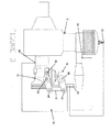
- an electronic fuel control system for an engine E for example a single piston two-stroke engine as used in a chainsaw, concrete saw, trimmers, lawnmower or the like. It will however be appreciated from the following description of the suitable carburettor based engine and/or multi carburettor and/or multi cylinder engines (not shown).
- the fuel control system 10 comprises a carburettor 12 secured to the engine E in conventional fashion.
- the carburettor 12 is a diaphragm type carburettor, although it will again be understood that any other suitable form of carburettor, for example a conventional float type carburettor or the like may be used.
- the fuel control system 10 further comprises an electronic controller 14 which is operable, as will be described hereinafter in detail, to receive data regarding one or more engine operating parameters, and to use this data to control, via an actuator 16, fuel metering in the carburettor 12.
- the data may be supplied to the controller 14 by any suitable means, for example through wired or wireless connections or the like, as will be described.
- the carburettor 12 comprises both an idle speed and a high-speed fuel circuit (not shown) extending between a fuel chamber (not shown) and a throttle bore (not shown) of the carburettor 12 in conventional fashion. Metering of the flow of fuel through both of these fuel circuits can be effected through an idle speed adjustment member 18 and a high-speed adjustment member 20 which in the embodiment illustrated take the form of screw type adjusters as illustrated in Figure 4 . Naturally it will be understood that the above mentioned metering may be achieved through any other suitable means and with alternative adjusting members as required.
- the adjusting members 18, 20 are seated within a respective threaded bore 22, 24 which each define a seat 26 or step change in diameter towards the inner end of the bore 22, 24.
- Each adjustment member 18, 20 has a tapered tip 28 which can be advanced towards or away from the respective seat 26 by turning the respective adjustment member 18. In this way the bore 22, 24 and more particularly the dimensions of the orifice defined between the seat 26 and the tapered tip 28, can be adjusted in order to meter or regulate the flow of fuel through the bore 22, 24. It will thus be appreciated that the adjustment members 18, 20 could be replaced with any other functional equivalent, which is capable of affecting the metering of the fuels in an adjustable manner.
- the adjustment members 18, 20 each include a slotted head 30 which permits the adjustment member 18, 20 to be manually adjusted using a screwdriver or the like. Again any other means of effecting adjustment of the members 18, 20. In this way the end user of the engine E can independently adjust the metering of the idle and high-speed fuel flows to suit particular operating and/or environmental conditions.
- the fuel control system 10 also permits the automatic control of one or both of the idle and high-speed fuel flow rates.
- the controller 14 is adapted to receive data from one or more sensors, for example a spark plug temperature sensor 32, an exhaust composition/temperature sensor 34, a manifold sensor 36, or any other suitable sensor, for example pressure, speed, or other sensors. These sensors may be hard wired to the controller 14, or may communicate wirelessly or by any other suitable manner.
- the controller 14 Based on the information received from one or more of the sensors the controller 14 sends a signal to the actuator 16, which can then be utilised to effect rotation of, in the embodiment illustrated, the high-speed adjustment member 20 in order to meter the flow of fuel in the high-speed fuel circuit such as to suit the prevailing operation conditions as established from the data collected by one or more of the sensors.
- the actuator 16 could be utilised to control the idle speed adjustment member 18, or indeed both of the adjustment members 18, 20, whether independently or in combination. This allows the closed loop feedback control of the metering of fuel in the carburettor 12.
- the actuator 16 comprises a motor 38 by which is driven a first lever 40 forming part of the actuator 16.
- the first lever 40 is connected via a link 42 to a second lever 44 whose fulcrum is coaxial with a longitudinal axis of the high-speed adjustment member 20.
- the first lever 40 may be rotated by the motor 38, which is operated by the actuator 16, in order to effect rotation of the second lever 44.
- Rotation of the second lever 44 effects rotation of the high-speed adjustment member 20 in order to achieve the desired fuel flow metering.
- the linkage arrangement of the first and second levers 40, 44 and the connecting link 42 could be replaced with any other suitable functional alternative which will allow displacement of the adjustment member 18, 20.
- the high-speed adjustment member 20 (and optionally the idle adjustment member 18) can be automatically operated to allow more or less fuel to be fed to the engine via the carburettor 12, based on the information gathered by the electronic controller 14 from the various sensors.
- the electronic fuel control system 10 is also preferably provided with an override in the form of a circuit breaker 46 which allows the manual and/or automatic disabling of the controller 14, wherein the actuator 16 will allow the high-speed adjustment member 20 to return to a predetermined position/configuration, for example to reset to factory settings.
- the actuator 16 may for example be spring based to return to this position.
- the fuel control system 10 may then be manually controlled by the engine operator without the input from the various sensors mounted about the engine E.
Landscapes
- Engineering & Computer Science (AREA)
- Chemical & Material Sciences (AREA)
- Combustion & Propulsion (AREA)
- Mechanical Engineering (AREA)
- General Engineering & Computer Science (AREA)
- Electrical Control Of Air Or Fuel Supplied To Internal-Combustion Engine (AREA)
- Control Of Throttle Valves Provided In The Intake System Or In The Exhaust System (AREA)
Abstract
Description
- The present invention relates to an electronic fuel control system for adjusting fuel flow through a carburettor to an engine, and is especially but not exclusively applicable to a carburettor for supplying fuel to two or four stroke engines designed for use on, for example, chain saws, concrete saws, trimmers, lawn mowers, go-karts, motor cars, race cars, motorcycles and aircraft.
- A diaphragm-type carburettor comprises a main body portion defining a carburettor mixing passage or bore having an air intake side and an engine outlet side, fuel pump means, a throttle shutter mounted within the carburettor mixing passage between the air intake side and the engine outlet side, a throttle shaft for controlling the throttle shutter, and a metering chamber for supplying fuel from the fuel pump means into the carburettor mixing passage via a high-speed adjusting screw and a low speed/idle adjusting screw.
- In such a carburettor the volume of fuel delivered to engine is adjustable, for low speed operation via low speed/idle adjustment screw and for high-speed operation via the high-speed adjustment screw. Adjustment is factory set by the engine manufacturer to give the desired engine performance/air fuel ratios.
- With such a system, adjustment can be made within a broad band from no fuel flow, when the adjustment needle is screwed fully in (i.e. the needle tip closes the orifice) to fully open, when the needle tip is fully out of the orifice. In this case the orifice diameter controls the maximum volume of fuel flow. This system allows the engine to be set to run on a very lean or very rich fuel fixture. More often the factory setting is re-adjusted by the end user because of acceleration problems due to the carburettor supplying insufficient fuel on acceleration and or altitude conditions where by the engine runs lean or rich due to the altitude. This arises from the inertia of moving components and machining in the carburettor, as well as high temperatures, pressures and vibration from the engine to which the carburettor is fitted. If sufficient fuel is supplied for acceleration, this can lead to an over supply at other times, causing engine performance problems in start-up, warm-up, lower and part throttle positions.
- It is an object of the present invention to provide an electronic control system for a carburettor in which the above problem can be avoided.
- This invention addresses the above problem by providing a fuel control system for a carburettor which has the ability to supply the correct quantity of fuel when required throughout the full range of operation or may be set to cover only a particular section of the full range of operation, primarily allowing the engine to have stable operation.
- According to the present invention there is provided an electronic fuel control system comprising a carburettor comprising a throttle bore, a fuel chamber, at least one fuel circuit extending between the fuel chamber and the throttle bore and controlled by an adjustment member; and an actuator operable to automatically adjust the adjustment member in response to one or more engine operating parameters.
- Preferably, the at least one fuel circuit comprises an idle fuel circuit extending between the fuel chamber and the throttle bore and controlled by an idle speed adjustment member, and a high-speed fuel circuit extending between the fuel chamber and the throttle bore and controlled by a high-speed adjustment member.
- Preferably, the carburettor comprises a diaphragm carburettor.
- Preferably, the fuel control system comprises a controller adapted to receive information regarding the one or more engine parameters and to effect operation of the actuator based on the received information.
- Preferably, the actuator comprises a motor, a first lever driven by the motor, a second lever driving the at least one adjustment member, and a link connecting the first and second levers together.
- Preferably, the fuel control system comprises one or more sensors adapted to receiving and transmit information regarding the one or more operating parameters to the controller.
- Preferably, the at least one adjustment member is operable to selectively expose/occlude an orifice in order to meter the flow of a fluid through the orifice.
- Preferably, the fuel control system comprises an override operable to enable a reset of the at least one adjustment member to a predetermined position.
- Preferably, the override is adapted to manually and/or automatically deactivate the controller.
- Preferably, the actuator is biased to return the at least one adjustment member to a predetermined position.
- Preferably, the carburettor comprises a choke.
- Preferably, the choke is operable by the controller.
- Preferably, the choke is remote from the carburettor.
- As used herein, the term "engine operating parameters" is intended to mean parameters such as engine temperature, engine speed, exhaust conditions and the like, in addition to external conditions such as environmental conditions like air temperature, pressure, humidity, etc, which can have a bearing on the operation of an engine.
- The invention will be understood in greater detail from the following description of a preferred embodiment of the invention given by way of example only and with reference to the accompanying drawings, in which:
-
Figure 1 illustrates a side view of an embodiment of fuel control system according to the present invention that includes a carburettor attached to an engine and having a pair of adjustment screws; -
Figure 2 illustrates a high-speed adjustment member of the carburettor in the lean adjustment range; -
Figure 3 illustrates the high-speed adjustment member ofFigure 2 in the rich adjustment range; and -
Figure 4 illustrates an enlarged and sectioned portion of the carburettor that details the function of the adjustment screw members. - Referring now to the accompanying drawings there is illustrated an electronic fuel control system for an engine E, for example a single piston two-stroke engine as used in a chainsaw, concrete saw, trimmers, lawnmower or the like. It will however be appreciated from the following description of the suitable carburettor based engine and/or multi carburettor and/or multi cylinder engines (not shown).
- The
fuel control system 10 comprises acarburettor 12 secured to the engine E in conventional fashion. In the embodiment illustrated thecarburettor 12 is a diaphragm type carburettor, although it will again be understood that any other suitable form of carburettor, for example a conventional float type carburettor or the like may be used. Thefuel control system 10 further comprises anelectronic controller 14 which is operable, as will be described hereinafter in detail, to receive data regarding one or more engine operating parameters, and to use this data to control, via anactuator 16, fuel metering in thecarburettor 12. The data may be supplied to thecontroller 14 by any suitable means, for example through wired or wireless connections or the like, as will be described. - The
carburettor 12 comprises both an idle speed and a high-speed fuel circuit (not shown) extending between a fuel chamber (not shown) and a throttle bore (not shown) of thecarburettor 12 in conventional fashion. Metering of the flow of fuel through both of these fuel circuits can be effected through an idlespeed adjustment member 18 and a high-speed adjustment member 20 which in the embodiment illustrated take the form of screw type adjusters as illustrated inFigure 4 . Naturally it will be understood that the above mentioned metering may be achieved through any other suitable means and with alternative adjusting members as required. - The adjusting
members bore seat 26 or step change in diameter towards the inner end of thebore adjustment member tapered tip 28 which can be advanced towards or away from therespective seat 26 by turning therespective adjustment member 18. In this way thebore seat 26 and thetapered tip 28, can be adjusted in order to meter or regulate the flow of fuel through thebore adjustment members - It can be seen that the
adjustment members head 30 which permits theadjustment member members fuel control system 10 also permits the automatic control of one or both of the idle and high-speed fuel flow rates. Thus thecontroller 14 is adapted to receive data from one or more sensors, for example a sparkplug temperature sensor 32, an exhaust composition/temperature sensor 34, amanifold sensor 36, or any other suitable sensor, for example pressure, speed, or other sensors. These sensors may be hard wired to thecontroller 14, or may communicate wirelessly or by any other suitable manner. - Based on the information received from one or more of the sensors the
controller 14 sends a signal to theactuator 16, which can then be utilised to effect rotation of, in the embodiment illustrated, the high-speed adjustment member 20 in order to meter the flow of fuel in the high-speed fuel circuit such as to suit the prevailing operation conditions as established from the data collected by one or more of the sensors. It will of course be appreciated that theactuator 16 could be utilised to control the idlespeed adjustment member 18, or indeed both of theadjustment members carburettor 12. - In the embodiment illustrated the
actuator 16 comprises amotor 38 by which is driven afirst lever 40 forming part of theactuator 16. Thefirst lever 40 is connected via alink 42 to asecond lever 44 whose fulcrum is coaxial with a longitudinal axis of the high-speed adjustment member 20. Thus thefirst lever 40 may be rotated by themotor 38, which is operated by theactuator 16, in order to effect rotation of thesecond lever 44. Rotation of thesecond lever 44 effects rotation of the high-speed adjustment member 20 in order to achieve the desired fuel flow metering. It will of course be understood that the linkage arrangement of the first andsecond levers link 42 could be replaced with any other suitable functional alternative which will allow displacement of theadjustment member - Thus the high-speed adjustment member 20 (and optionally the idle adjustment member 18) can be automatically operated to allow more or less fuel to be fed to the engine via the
carburettor 12, based on the information gathered by theelectronic controller 14 from the various sensors. - The electronic
fuel control system 10 is also preferably provided with an override in the form of acircuit breaker 46 which allows the manual and/or automatic disabling of thecontroller 14, wherein theactuator 16 will allow the high-speed adjustment member 20 to return to a predetermined position/configuration, for example to reset to factory settings. Theactuator 16 may for example be spring based to return to this position. Thefuel control system 10 may then be manually controlled by the engine operator without the input from the various sensors mounted about the engine E.
Claims (13)
- An electronic fuel control system comprising a carburettor comprising a throttle bore, a fuel chamber, at least one fuel circuit extending between the fuel chamber and the throttle bore and controlled by an adjustment member; and an actuator operable to automatically adjust the adjustment member in response to one or more engine operating parameters.
- An electronic fuel control system according to claim 1 in which the at least one fuel circuit comprises an idle fuel circuit extending between the fuel chamber and the throttle bore and controlled by an idle speed adjustment member, and a high-speed fuel circuit extending between the fuel chamber and the throttle bore and controlled by a high-speed adjustment member.
- An electronic fuel control system according to claim 1 or 2 in which the carburettor comprises a diaphragm carburettor.
- An electronic fuel control system according to any preceding claim comprising a controller adapted to receive information regarding the one or more engine parameters and to effect operation of the actuator based on the received information.
- An electronic fuel control system according to any preceding claim in which the actuator comprises a motor, a first lever driven by the motor, a second lever driving the at least one adjustment member, and a link connecting the first and second levers together.
- An electronic fuel control system according to any preceding claim comprising one or more sensors adapted to receive and transmit information regarding the one or more operating parameters to the controller.
- An electronic fuel control system according to any preceding claim in which the at least one adjustment member is operable to selectively expose/occlude an orifice in order to meter the flow of a fluid through the orifice.
- An electronic fuel control system according to any preceding claim comprising an override operable to enable a reset of the at least one adjustment member to a predetermined position.
- An electronic fuel control system according to claim 8, when dependent on claim 4, in which the override is adapted to manually and/or automatically deactivate the controller.
- An electronic fuel control system according to any preceding claim in which the actuator is biased to return the at least one adjustment member to a predetermined position.
- An electronic fuel control system according to any preceding claim in which the carburettor comprises a choke.
- An electronic fuel control system according to claim 11, when dependent on claim 4, in which the choke is operable by the controller.
- An electronic fuel control system according to claim 11 or 12 in which the choke is remote from the carburettor.
Applications Claiming Priority (1)
| Application Number | Priority Date | Filing Date | Title |
|---|---|---|---|
| IES20110135 | 2011-03-23 |
Publications (3)
| Publication Number | Publication Date |
|---|---|
| EP2503136A2 true EP2503136A2 (en) | 2012-09-26 |
| EP2503136A3 EP2503136A3 (en) | 2016-08-10 |
| EP2503136B1 EP2503136B1 (en) | 2020-12-16 |
Family
ID=46489128
Family Applications (1)
| Application Number | Title | Priority Date | Filing Date |
|---|---|---|---|
| EP12160794.9A Active EP2503136B1 (en) | 2011-03-23 | 2012-03-22 | Electronic fuel control system |
Country Status (3)
| Country | Link |
|---|---|
| US (1) | US8960154B2 (en) |
| EP (1) | EP2503136B1 (en) |
| IE (1) | IES20120149A2 (en) |
Families Citing this family (2)
| Publication number | Priority date | Publication date | Assignee | Title |
|---|---|---|---|---|
| JP6437373B2 (en) * | 2015-04-09 | 2018-12-12 | 株式会社やまびこ | Portable work machine |
| FR3119344B1 (en) * | 2021-01-29 | 2024-05-10 | Sodikart | KART WITH ADJUSTABLE POWER THERMAL ENGINE AND METHOD FOR CONTROLLING A CORRESPONDING KART |
Family Cites Families (12)
| Publication number | Priority date | Publication date | Assignee | Title |
|---|---|---|---|---|
| FR2270451A1 (en) * | 1974-05-06 | 1975-12-05 | Peugeot & Renault | Constant depression carburettor with electronic control - adjusts fuel flow according to oxygen content of exhaust gases |
| US4411233A (en) * | 1980-07-17 | 1983-10-25 | Societe Industrielle De Brevets Et D'etudes S.I.B.E. | Carburation devices for internal combustion engines |
| US4577597A (en) * | 1981-06-18 | 1986-03-25 | Honda Giken Kogyo Kabushiki Kaisha | Method and apparatus for supplying fuel to internal combustion engine |
| DE4411634A1 (en) * | 1994-04-02 | 1995-10-05 | Stihl Maschf Andreas | Membrane carburettor for hand operated equipment IC engine |
| US5611312A (en) * | 1995-02-07 | 1997-03-18 | Walbro Corporation | Carburetor and method and apparatus for controlling air/fuel ratio of same |
| JPH08312420A (en) * | 1995-05-17 | 1996-11-26 | Futaba Corp | Control method and device of model engine |
| US5632248A (en) * | 1995-06-06 | 1997-05-27 | Mikuni Corporation | Electronically controlled type floatless carburetor |
| JP2003343358A (en) * | 2002-05-27 | 2003-12-03 | Zama Japan Kk | Carburetor |
| JP2003343359A (en) * | 2002-05-30 | 2003-12-03 | Zama Japan Kk | Carburetor |
| JP2004360685A (en) * | 2003-05-12 | 2004-12-24 | Yamaha Motor Co Ltd | Engine starting device and straddle-type traveling vehicle |
| WO2007133126A1 (en) * | 2006-05-12 | 2007-11-22 | Husqvarna Aktiebolag | Method for controlling fuel supply to a crankcase scavenged internal combustion engine |
| PL2290217T3 (en) * | 2008-03-17 | 2016-12-30 | Fuel supply unit |
-
2012
- 2012-03-22 EP EP12160794.9A patent/EP2503136B1/en active Active
- 2012-03-22 IE IE20120149A patent/IES20120149A2/en unknown
- 2012-03-23 US US13/427,974 patent/US8960154B2/en active Active
Non-Patent Citations (1)
| Title |
|---|
| None |
Also Published As
| Publication number | Publication date |
|---|---|
| IES20120149A2 (en) | 2012-06-20 |
| EP2503136A3 (en) | 2016-08-10 |
| EP2503136B1 (en) | 2020-12-16 |
| US20120272936A1 (en) | 2012-11-01 |
| US8960154B2 (en) | 2015-02-24 |
Similar Documents
| Publication | Publication Date | Title |
|---|---|---|
| US5709822A (en) | Fuel regulating mechanism for a rotary throttle valve type carburetor | |
| CN101344050B (en) | Carburetor and method of operating the same | |
| JP2003184654A (en) | Rotary throttle valve type carburetor and method for fuel supply adjustment | |
| US8683983B2 (en) | Method for regulating a stationary gas engine | |
| US20100256890A1 (en) | Method for Controlling a Stationary Gas Motor | |
| CN101338709B (en) | Arrangement of an air filter and a diaphragm carburettor | |
| US6581916B1 (en) | Electronic control diaphragm carburetor | |
| JPH08324496A (en) | Control device for aircraft propulsion engine | |
| CA2278996C (en) | Carburetor with secured control screw | |
| EP2787194B1 (en) | Internal combustion engine | |
| EP2503136B1 (en) | Electronic fuel control system | |
| US5002705A (en) | Carburetor including an idling adjustment system | |
| JPS6128028Y2 (en) | ||
| EP1243776A1 (en) | Combined control of dual fuel system for diesel cycle engines | |
| US10495017B2 (en) | Portable working machine including engine with carburetor and fuel supply control method thereof | |
| JP2004225694A (en) | 2-cycle engine and method for its actuation | |
| IE20120149U1 (en) | Electronic fuel control system | |
| US6234456B1 (en) | Diaphragm carburetor | |
| IES86009Y1 (en) | Electronic fuel control system | |
| JPH04503389A (en) | Air supply system for internal combustion engines | |
| US2551836A (en) | Regulator | |
| EP3032173B1 (en) | Gas type adaption device for a gas burner application and gas/air mixing device for a gas burner application comprising a gas type adaption device | |
| US4052488A (en) | Supplying fuel to internal combustion engines | |
| EP3491232B1 (en) | Method for controlling the operation of a two-stroke spark ignition internal combustion engine | |
| WO2009109103A1 (en) | A gas mixer of universal small combustion-gas engine for automatically controlling amount of combustion gas |
Legal Events
| Date | Code | Title | Description |
|---|---|---|---|
| PUAI | Public reference made under article 153(3) epc to a published international application that has entered the european phase |
Free format text: ORIGINAL CODE: 0009012 |
|
| AK | Designated contracting states |
Kind code of ref document: A2 Designated state(s): AL AT BE BG CH CY CZ DE DK EE ES FI FR GB GR HR HU IE IS IT LI LT LU LV MC MK MT NL NO PL PT RO RS SE SI SK SM TR |
|
| AX | Request for extension of the european patent |
Extension state: BA ME |
|
| PUAL | Search report despatched |
Free format text: ORIGINAL CODE: 0009013 |
|
| AK | Designated contracting states |
Kind code of ref document: A3 Designated state(s): AL AT BE BG CH CY CZ DE DK EE ES FI FR GB GR HR HU IE IS IT LI LT LU LV MC MK MT NL NO PL PT RO RS SE SI SK SM TR |
|
| AX | Request for extension of the european patent |
Extension state: BA ME |
|
| RIC1 | Information provided on ipc code assigned before grant |
Ipc: F02M 19/02 20060101ALI20160701BHEP Ipc: F02D 35/00 20060101AFI20160701BHEP Ipc: F02M 17/04 20060101ALN20160701BHEP |
|
| RBV | Designated contracting states (corrected) |
Designated state(s): AL AT BE BG CH CY CZ DE DK EE ES FI FR GB GR HR HU IE IS IT LI LT LU LV MC MK MT NL NO PL PT RO RS SE SI SK SM TR |
|
| STAA | Information on the status of an ep patent application or granted ep patent |
Free format text: STATUS: REQUEST FOR EXAMINATION WAS MADE |
|
| 17P | Request for examination filed |
Effective date: 20170209 |
|
| STAA | Information on the status of an ep patent application or granted ep patent |
Free format text: STATUS: EXAMINATION IS IN PROGRESS |
|
| 17Q | First examination report despatched |
Effective date: 20180207 |
|
| REG | Reference to a national code |
Ref country code: DE Ref legal event code: R079 Ref document number: 602012073718 Country of ref document: DE Free format text: PREVIOUS MAIN CLASS: F02M0017040000 Ipc: F02D0035000000 |
|
| GRAP | Despatch of communication of intention to grant a patent |
Free format text: ORIGINAL CODE: EPIDOSNIGR1 |
|
| STAA | Information on the status of an ep patent application or granted ep patent |
Free format text: STATUS: GRANT OF PATENT IS INTENDED |
|
| RIC1 | Information provided on ipc code assigned before grant |
Ipc: F02M 17/04 20060101ALN20200903BHEP Ipc: F02M 19/02 20060101ALI20200903BHEP Ipc: F02D 35/00 20060101AFI20200903BHEP |
|
| INTG | Intention to grant announced |
Effective date: 20201002 |
|
| GRAS | Grant fee paid |
Free format text: ORIGINAL CODE: EPIDOSNIGR3 |
|
| GRAA | (expected) grant |
Free format text: ORIGINAL CODE: 0009210 |
|
| STAA | Information on the status of an ep patent application or granted ep patent |
Free format text: STATUS: THE PATENT HAS BEEN GRANTED |
|
| AK | Designated contracting states |
Kind code of ref document: B1 Designated state(s): AL AT BE BG CH CY CZ DE DK EE ES FI FR GB GR HR HU IE IS IT LI LT LU LV MC MK MT NL NO PL PT RO RS SE SI SK SM TR |
|
| REG | Reference to a national code |
Ref country code: GB Ref legal event code: FG4D |
|
| REG | Reference to a national code |
Ref country code: IE Ref legal event code: FG4D |
|
| REG | Reference to a national code |
Ref country code: DE Ref legal event code: R096 Ref document number: 602012073718 Country of ref document: DE |
|
| REG | Reference to a national code |
Ref country code: AT Ref legal event code: REF Ref document number: 1345813 Country of ref document: AT Kind code of ref document: T Effective date: 20210115 |
|
| PG25 | Lapsed in a contracting state [announced via postgrant information from national office to epo] |
Ref country code: NO Free format text: LAPSE BECAUSE OF FAILURE TO SUBMIT A TRANSLATION OF THE DESCRIPTION OR TO PAY THE FEE WITHIN THE PRESCRIBED TIME-LIMIT Effective date: 20210316 Ref country code: FI Free format text: LAPSE BECAUSE OF FAILURE TO SUBMIT A TRANSLATION OF THE DESCRIPTION OR TO PAY THE FEE WITHIN THE PRESCRIBED TIME-LIMIT Effective date: 20201216 Ref country code: RS Free format text: LAPSE BECAUSE OF FAILURE TO SUBMIT A TRANSLATION OF THE DESCRIPTION OR TO PAY THE FEE WITHIN THE PRESCRIBED TIME-LIMIT Effective date: 20201216 Ref country code: GR Free format text: LAPSE BECAUSE OF FAILURE TO SUBMIT A TRANSLATION OF THE DESCRIPTION OR TO PAY THE FEE WITHIN THE PRESCRIBED TIME-LIMIT Effective date: 20210317 |
|
| REG | Reference to a national code |
Ref country code: AT Ref legal event code: MK05 Ref document number: 1345813 Country of ref document: AT Kind code of ref document: T Effective date: 20201216 |
|
| REG | Reference to a national code |
Ref country code: NL Ref legal event code: MP Effective date: 20201216 |
|
| PG25 | Lapsed in a contracting state [announced via postgrant information from national office to epo] |
Ref country code: SE Free format text: LAPSE BECAUSE OF FAILURE TO SUBMIT A TRANSLATION OF THE DESCRIPTION OR TO PAY THE FEE WITHIN THE PRESCRIBED TIME-LIMIT Effective date: 20201216 Ref country code: LV Free format text: LAPSE BECAUSE OF FAILURE TO SUBMIT A TRANSLATION OF THE DESCRIPTION OR TO PAY THE FEE WITHIN THE PRESCRIBED TIME-LIMIT Effective date: 20201216 Ref country code: BG Free format text: LAPSE BECAUSE OF FAILURE TO SUBMIT A TRANSLATION OF THE DESCRIPTION OR TO PAY THE FEE WITHIN THE PRESCRIBED TIME-LIMIT Effective date: 20210316 |
|
| PG25 | Lapsed in a contracting state [announced via postgrant information from national office to epo] |
Ref country code: HR Free format text: LAPSE BECAUSE OF FAILURE TO SUBMIT A TRANSLATION OF THE DESCRIPTION OR TO PAY THE FEE WITHIN THE PRESCRIBED TIME-LIMIT Effective date: 20201216 Ref country code: NL Free format text: LAPSE BECAUSE OF FAILURE TO SUBMIT A TRANSLATION OF THE DESCRIPTION OR TO PAY THE FEE WITHIN THE PRESCRIBED TIME-LIMIT Effective date: 20201216 |
|
| REG | Reference to a national code |
Ref country code: LT Ref legal event code: MG9D |
|
| PG25 | Lapsed in a contracting state [announced via postgrant information from national office to epo] |
Ref country code: LT Free format text: LAPSE BECAUSE OF FAILURE TO SUBMIT A TRANSLATION OF THE DESCRIPTION OR TO PAY THE FEE WITHIN THE PRESCRIBED TIME-LIMIT Effective date: 20201216 Ref country code: RO Free format text: LAPSE BECAUSE OF FAILURE TO SUBMIT A TRANSLATION OF THE DESCRIPTION OR TO PAY THE FEE WITHIN THE PRESCRIBED TIME-LIMIT Effective date: 20201216 Ref country code: SK Free format text: LAPSE BECAUSE OF FAILURE TO SUBMIT A TRANSLATION OF THE DESCRIPTION OR TO PAY THE FEE WITHIN THE PRESCRIBED TIME-LIMIT Effective date: 20201216 Ref country code: PT Free format text: LAPSE BECAUSE OF FAILURE TO SUBMIT A TRANSLATION OF THE DESCRIPTION OR TO PAY THE FEE WITHIN THE PRESCRIBED TIME-LIMIT Effective date: 20210416 Ref country code: CZ Free format text: LAPSE BECAUSE OF FAILURE TO SUBMIT A TRANSLATION OF THE DESCRIPTION OR TO PAY THE FEE WITHIN THE PRESCRIBED TIME-LIMIT Effective date: 20201216 Ref country code: EE Free format text: LAPSE BECAUSE OF FAILURE TO SUBMIT A TRANSLATION OF THE DESCRIPTION OR TO PAY THE FEE WITHIN THE PRESCRIBED TIME-LIMIT Effective date: 20201216 Ref country code: SM Free format text: LAPSE BECAUSE OF FAILURE TO SUBMIT A TRANSLATION OF THE DESCRIPTION OR TO PAY THE FEE WITHIN THE PRESCRIBED TIME-LIMIT Effective date: 20201216 |
|
| PG25 | Lapsed in a contracting state [announced via postgrant information from national office to epo] |
Ref country code: PL Free format text: LAPSE BECAUSE OF FAILURE TO SUBMIT A TRANSLATION OF THE DESCRIPTION OR TO PAY THE FEE WITHIN THE PRESCRIBED TIME-LIMIT Effective date: 20201216 Ref country code: AT Free format text: LAPSE BECAUSE OF FAILURE TO SUBMIT A TRANSLATION OF THE DESCRIPTION OR TO PAY THE FEE WITHIN THE PRESCRIBED TIME-LIMIT Effective date: 20201216 |
|
| REG | Reference to a national code |
Ref country code: DE Ref legal event code: R097 Ref document number: 602012073718 Country of ref document: DE |
|
| PG25 | Lapsed in a contracting state [announced via postgrant information from national office to epo] |
Ref country code: IS Free format text: LAPSE BECAUSE OF FAILURE TO SUBMIT A TRANSLATION OF THE DESCRIPTION OR TO PAY THE FEE WITHIN THE PRESCRIBED TIME-LIMIT Effective date: 20210416 |
|
| PLBE | No opposition filed within time limit |
Free format text: ORIGINAL CODE: 0009261 |
|
| STAA | Information on the status of an ep patent application or granted ep patent |
Free format text: STATUS: NO OPPOSITION FILED WITHIN TIME LIMIT |
|
| PG25 | Lapsed in a contracting state [announced via postgrant information from national office to epo] |
Ref country code: MC Free format text: LAPSE BECAUSE OF FAILURE TO SUBMIT A TRANSLATION OF THE DESCRIPTION OR TO PAY THE FEE WITHIN THE PRESCRIBED TIME-LIMIT Effective date: 20201216 Ref country code: AL Free format text: LAPSE BECAUSE OF FAILURE TO SUBMIT A TRANSLATION OF THE DESCRIPTION OR TO PAY THE FEE WITHIN THE PRESCRIBED TIME-LIMIT Effective date: 20201216 |
|
| REG | Reference to a national code |
Ref country code: CH Ref legal event code: PL |
|
| 26N | No opposition filed |
Effective date: 20210917 |
|
| GBPC | Gb: european patent ceased through non-payment of renewal fee |
Effective date: 20210322 |
|
| PG25 | Lapsed in a contracting state [announced via postgrant information from national office to epo] |
Ref country code: DK Free format text: LAPSE BECAUSE OF FAILURE TO SUBMIT A TRANSLATION OF THE DESCRIPTION OR TO PAY THE FEE WITHIN THE PRESCRIBED TIME-LIMIT Effective date: 20201216 Ref country code: ES Free format text: LAPSE BECAUSE OF FAILURE TO SUBMIT A TRANSLATION OF THE DESCRIPTION OR TO PAY THE FEE WITHIN THE PRESCRIBED TIME-LIMIT Effective date: 20201216 |
|
| REG | Reference to a national code |
Ref country code: BE Ref legal event code: MM Effective date: 20210331 |
|
| PG25 | Lapsed in a contracting state [announced via postgrant information from national office to epo] |
Ref country code: GB Free format text: LAPSE BECAUSE OF NON-PAYMENT OF DUE FEES Effective date: 20210322 Ref country code: IE Free format text: LAPSE BECAUSE OF NON-PAYMENT OF DUE FEES Effective date: 20210322 Ref country code: CH Free format text: LAPSE BECAUSE OF NON-PAYMENT OF DUE FEES Effective date: 20210331 Ref country code: LU Free format text: LAPSE BECAUSE OF NON-PAYMENT OF DUE FEES Effective date: 20210322 Ref country code: LI Free format text: LAPSE BECAUSE OF NON-PAYMENT OF DUE FEES Effective date: 20210331 |
|
| PG25 | Lapsed in a contracting state [announced via postgrant information from national office to epo] |
Ref country code: SI Free format text: LAPSE BECAUSE OF FAILURE TO SUBMIT A TRANSLATION OF THE DESCRIPTION OR TO PAY THE FEE WITHIN THE PRESCRIBED TIME-LIMIT Effective date: 20201216 |
|
| PG25 | Lapsed in a contracting state [announced via postgrant information from national office to epo] |
Ref country code: IS Free format text: LAPSE BECAUSE OF FAILURE TO SUBMIT A TRANSLATION OF THE DESCRIPTION OR TO PAY THE FEE WITHIN THE PRESCRIBED TIME-LIMIT Effective date: 20210416 |
|
| PG25 | Lapsed in a contracting state [announced via postgrant information from national office to epo] |
Ref country code: BE Free format text: LAPSE BECAUSE OF NON-PAYMENT OF DUE FEES Effective date: 20210331 |
|
| PG25 | Lapsed in a contracting state [announced via postgrant information from national office to epo] |
Ref country code: HU Free format text: LAPSE BECAUSE OF FAILURE TO SUBMIT A TRANSLATION OF THE DESCRIPTION OR TO PAY THE FEE WITHIN THE PRESCRIBED TIME-LIMIT; INVALID AB INITIO Effective date: 20120322 Ref country code: CY Free format text: LAPSE BECAUSE OF FAILURE TO SUBMIT A TRANSLATION OF THE DESCRIPTION OR TO PAY THE FEE WITHIN THE PRESCRIBED TIME-LIMIT Effective date: 20201216 |
|
| PG25 | Lapsed in a contracting state [announced via postgrant information from national office to epo] |
Ref country code: MK Free format text: LAPSE BECAUSE OF FAILURE TO SUBMIT A TRANSLATION OF THE DESCRIPTION OR TO PAY THE FEE WITHIN THE PRESCRIBED TIME-LIMIT Effective date: 20201216 |
|
| PG25 | Lapsed in a contracting state [announced via postgrant information from national office to epo] |
Ref country code: MT Free format text: LAPSE BECAUSE OF FAILURE TO SUBMIT A TRANSLATION OF THE DESCRIPTION OR TO PAY THE FEE WITHIN THE PRESCRIBED TIME-LIMIT Effective date: 20201216 |
|
| PGFP | Annual fee paid to national office [announced via postgrant information from national office to epo] |
Ref country code: IT Payment date: 20250331 Year of fee payment: 14 |
|
| PG25 | Lapsed in a contracting state [announced via postgrant information from national office to epo] |
Ref country code: TR Free format text: LAPSE BECAUSE OF FAILURE TO SUBMIT A TRANSLATION OF THE DESCRIPTION OR TO PAY THE FEE WITHIN THE PRESCRIBED TIME-LIMIT Effective date: 20201216 |
|
| PGFP | Annual fee paid to national office [announced via postgrant information from national office to epo] |
Ref country code: DE Payment date: 20260320 Year of fee payment: 15 |
|
| PGFP | Annual fee paid to national office [announced via postgrant information from national office to epo] |
Ref country code: FR Payment date: 20260325 Year of fee payment: 15 |