EP2502883A1 - Black water treatment systems and methods - Google Patents
Black water treatment systems and methods Download PDFInfo
- Publication number
- EP2502883A1 EP2502883A1 EP12160040A EP12160040A EP2502883A1 EP 2502883 A1 EP2502883 A1 EP 2502883A1 EP 12160040 A EP12160040 A EP 12160040A EP 12160040 A EP12160040 A EP 12160040A EP 2502883 A1 EP2502883 A1 EP 2502883A1
- Authority
- EP
- European Patent Office
- Prior art keywords
- flow
- black water
- water
- treatment system
- black
- Prior art date
- Legal status (The legal status is an assumption and is not a legal conclusion. Google has not performed a legal analysis and makes no representation as to the accuracy of the status listed.)
- Granted
Links
Images
Classifications
-
- C—CHEMISTRY; METALLURGY
- C02—TREATMENT OF WATER, WASTE WATER, SEWAGE, OR SLUDGE
- C02F—TREATMENT OF WATER, WASTE WATER, SEWAGE, OR SLUDGE
- C02F1/00—Treatment of water, waste water, or sewage
- C02F1/20—Treatment of water, waste water, or sewage by degassing, i.e. liberation of dissolved gases
-
- C—CHEMISTRY; METALLURGY
- C02—TREATMENT OF WATER, WASTE WATER, SEWAGE, OR SLUDGE
- C02F—TREATMENT OF WATER, WASTE WATER, SEWAGE, OR SLUDGE
- C02F1/00—Treatment of water, waste water, or sewage
- C02F1/02—Treatment of water, waste water, or sewage by heating
- C02F1/04—Treatment of water, waste water, or sewage by heating by distillation or evaporation
- C02F1/08—Thin film evaporation
-
- B—PERFORMING OPERATIONS; TRANSPORTING
- B01—PHYSICAL OR CHEMICAL PROCESSES OR APPARATUS IN GENERAL
- B01D—SEPARATION
- B01D19/00—Degasification of liquids
- B01D19/0036—Flash degasification
-
- B—PERFORMING OPERATIONS; TRANSPORTING
- B01—PHYSICAL OR CHEMICAL PROCESSES OR APPARATUS IN GENERAL
- B01D—SEPARATION
- B01D3/00—Distillation or related exchange processes in which liquids are contacted with gaseous media, e.g. stripping
- B01D3/06—Flash distillation
-
- B—PERFORMING OPERATIONS; TRANSPORTING
- B01—PHYSICAL OR CHEMICAL PROCESSES OR APPARATUS IN GENERAL
- B01D—SEPARATION
- B01D5/00—Condensation of vapours; Recovering volatile solvents by condensation
-
- C—CHEMISTRY; METALLURGY
- C02—TREATMENT OF WATER, WASTE WATER, SEWAGE, OR SLUDGE
- C02F—TREATMENT OF WATER, WASTE WATER, SEWAGE, OR SLUDGE
- C02F1/00—Treatment of water, waste water, or sewage
- C02F1/52—Treatment of water, waste water, or sewage by flocculation or precipitation of suspended impurities
-
- C—CHEMISTRY; METALLURGY
- C02—TREATMENT OF WATER, WASTE WATER, SEWAGE, OR SLUDGE
- C02F—TREATMENT OF WATER, WASTE WATER, SEWAGE, OR SLUDGE
- C02F1/00—Treatment of water, waste water, or sewage
- C02F2001/007—Processes including a sedimentation step
-
- C—CHEMISTRY; METALLURGY
- C02—TREATMENT OF WATER, WASTE WATER, SEWAGE, OR SLUDGE
- C02F—TREATMENT OF WATER, WASTE WATER, SEWAGE, OR SLUDGE
- C02F2103/00—Nature of the water, waste water, sewage or sludge to be treated
- C02F2103/34—Nature of the water, waste water, sewage or sludge to be treated from industrial activities not provided for in groups C02F2103/12 - C02F2103/32
- C02F2103/36—Nature of the water, waste water, sewage or sludge to be treated from industrial activities not provided for in groups C02F2103/12 - C02F2103/32 from the manufacture of organic compounds
- C02F2103/365—Nature of the water, waste water, sewage or sludge to be treated from industrial activities not provided for in groups C02F2103/12 - C02F2103/32 from the manufacture of organic compounds from petrochemical industry (e.g. refineries)
-
- C—CHEMISTRY; METALLURGY
- C10—PETROLEUM, GAS OR COKE INDUSTRIES; TECHNICAL GASES CONTAINING CARBON MONOXIDE; FUELS; LUBRICANTS; PEAT
- C10J—PRODUCTION OF PRODUCER GAS, WATER-GAS, SYNTHESIS GAS FROM SOLID CARBONACEOUS MATERIAL, OR MIXTURES CONTAINING THESE GASES; CARBURETTING AIR OR OTHER GASES
- C10J2300/00—Details of gasification processes
- C10J2300/16—Integration of gasification processes with another plant or parts within the plant
- C10J2300/169—Integration of gasification processes with another plant or parts within the plant with water treatments
-
- C—CHEMISTRY; METALLURGY
- C10—PETROLEUM, GAS OR COKE INDUSTRIES; TECHNICAL GASES CONTAINING CARBON MONOXIDE; FUELS; LUBRICANTS; PEAT
- C10J—PRODUCTION OF PRODUCER GAS, WATER-GAS, SYNTHESIS GAS FROM SOLID CARBONACEOUS MATERIAL, OR MIXTURES CONTAINING THESE GASES; CARBURETTING AIR OR OTHER GASES
- C10J2300/00—Details of gasification processes
- C10J2300/18—Details of the gasification process, e.g. loops, autothermal operation
- C10J2300/1807—Recycle loops, e.g. gas, solids, heating medium, water
Definitions
- the present application and the resultant patent relate generally to the production of syngas and more particularly relate to systems and methods for the treatment and recycling of a flow of black water that results therefrom with reduced parasitical energy losses.
- synthetic gas may be produced in a gasification reactor by reacting a carbonaceous fuel in a partial oxidation process.
- the syngas then may be sent to a number of scrubbers for removing contaminants and fine particles therein.
- the syngas may include hydrogen sulfide, ammonia, cyanides, phenols, various halogens, and particulates in the form of carbon, ash, coal, trace metals, and the like. These contaminants and fines must be disposed of in a satisfactory manner for the gasification process to be economically and environmentally viable.
- water may be used in the gasification reactor for quenching the syngas. Further, water also may be used in the scrubbers for removing the fines.
- the water used in the scrubbers may become what is known as "black water” because it is contaminated with carbon, ash, and the like.
- the black water also may contain soluble gases therein.
- the black water may have about five percent (5%) to about ten percent (10%) by weight of suspended solids therein and may have an initial temperature of about 300 degrees Celsius or more.
- a flash system may include a number of flash drums positioned in stages from high pressure, to low pressure, to low vacuum, and to high vacuum. The vacuum stages not only help to remove the dissolve gases, but also help to cool the black water.
- the black water from the flash system may be sent to a gravity settler.
- the fines may be removed and clear water may be recycled in the gravity settler.
- the solids from the gravity settler then may be sent for grinding to prepare a slurry that may be fed to the gasifier and combusted therein.
- flash drums up to atmospheric pressure may be economical in that no additional energy is required to remove the dissolved gases.
- flashing in vacuuming conditions generally requires large equipment with significant energy demands and maintenance requirements. Specifically, such a vacuum system requires large amounts of energy in that the flash drums remove only dissolved gases but also a significant quantity of water vapor. High cooling water consumption therefore may be required to condense the water vapor. This water and energy consumption is considered a parasitical loss on the power plant as a whole.
- Such improved systems and methods may treat and recycle black water produced by a gasifier and the like without requiring the large devices and high energy demands found in known flash systems using vacuum conditions.
- the present disclosure provides a black water treatment system for a flow of black water.
- the black water treatment system may include one or more non-vacuum flash drums and a scrub-cooler.
- the scrub-cooler may include a water pathway with a nitrogen tube and a flow of nitrogen therein.
- the present disclosure further provides a method of treating a flow of black water.
- the method may include the steps of flashing the flow of black water to atmospheric pressure, inserting a flow of nitrogen into the flow of black water to agitate the flow of black water and to strip dissolved gases in the flow of black water, and indirectly cooling the flow of black water.
- the present disclosure further provides a black water treatment system for a flow of black water.
- the black water treatment system may include a high pressure flash drum, an atmospheric pressure flash drum, and a scrub-cooler.
- the scrub-cooler may include a water pathway with a nitrogen tube and a flow of nitrogen therein.
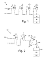
- Fig. 1 shows an example of a portion of a known black water treatment system 10.
- the black water treatment system 10 may include a flash system 15.
- the flash system 15 may include a high pressure flash drum 20, a low pressure flash drum 25, a low vacuum flash drum 30, and a high vacuum flash drum 35. Other types of flash drums also may be used.
- the flash system 15 serves to remove dissolved gases in a flow of black water 35 and also to cool the fluid stream. Other components and other configurations may be used herein.
- the flow of black water 40 is sent through the flash system 15 so as to reduce the temperature and pressure while increasing the flow rate.
- the black water 40 then may be sent to a gravity settler 45 where a collection of fines 50 settles in the bottom and leaves a flow of clear water 55 on top.
- the clear water 55 may be used for cooling and other purposes.
- Fig. 2 shows a black water treatment system 100 as may be described herein.
- the black water treatment system 100 cleans and recycles one or more flows of black water 110.
- the black water treatment system 100 may include a flash system 120. In the flash system 120, however, only a number of non-vacuum flash drums 125 may be used: a high pressure flash drum 130 and an atmospheric pressure flash drum 140. The flow of black water 110 thus is flashed to atmospheric pressure in the flash drums 130, 140 as opposed to a vacuum as is described above. Other types and numbers of non-vacuum flash drums 125 may be used herein.
- the flow of black water 110 then may be sent to a scrubbing and cooling vessel 150 ("a scrub-cooler").
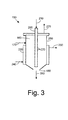
- a scrub-cooler An example of the scrub-cooler 150 is shown in Fig. 3 .
- the scrub-cooler 150 may have an internal water pathway 160 extending from a water entry port 170 in communication with the flash system 120 and a water exit port 180.
- the water exit port 180 may be in communication with a gravity settler 190 and the like.
- the scrub-cooler 150 also may include an internal nitrogen tube 200.
- the nitrogen tube 200 may have a flow of nitrogen 210 therein.
- the nitrogen tube 200 may have a number of tube apertures 220 positioned thereon. Any number or shape of the tube apertures 220 may be used herein.
- the nitrogen tube 200 extends along the length of the water pathway 160.
- a water jacket 230 may surround the scrub-cooler 150.
- the water jacket 230 may have a cooling water supply port 240 and a cooling water return port 250 in communication with a cooling water source (not shown).
- the water jacket 230 provides indirect cooling to the flow of black water 110.
- the scrub-cooler 150 uses the flow of nitrogen 210 as a scrubbing media and for agitation of the flow of black water 110. Specifically, the flow of nitrogen strips 210 dissolved gases in the flow of black water 110 and cools the flow to a lower temperature. The final desired temperature may be achieved by further cooling the black water 110 via the water jacket 230. Moreover, sparging the flow of nitrogen 210 in the black water flow 110 provides agitation for enhanced heat transfer. The flow of nitrogen 210 bubbles through the tube apertures 230 and rises through the liquid towards the surface. Bubbles in the flow of nitrogen 210 may be compressed by hydrostatic pressure and thus expand on the way towards the surface. The scrub-cooler 150 therefore may take an elongated shape 260 so as to make the path to the flow of nitrogen 210 as long as possible for improved interaction therein. A nitrogen vent 270 may be used herein to vent the nitrogen bubbles and the like.
- the flow of black water 110 enters the black water treatment system 100 via the flash system 120.
- the flow of black water 110 passes through the high pressure flash drum 130 and the atmospheric pressure flash drum 140 for a reduction in temperature and pressure.
- the flow of black water 110 then enters the scrub-cooler 150 via the water entry port 170.
- the flow of nitrogen 210 enters the nitrogen tube 200 and flows through the tube apertures 220.
- the flow of nitrogen 210 thus provides both agitation and scrubbing in the flow of black water 110.
- the flow of black water 110 may be further cooled via the water jacket 230 as it passes therethrough.
- a now scrubbed flow 280 thus may exit the scrub-cooler 150 via the water exit port 180.
- the scrubbed flow 280 may pass to a gravity settler 190 or other device so as to separate out the fines 290 and the flow of clear water 300 as described above.
- the black water treatment system 100 thus provides cooling for the flow of black water 110 without the uses of the vacuum flash drums 30, 35 described above.
- the black water treatment system 100 therefore does not require a vacuum system and the associated parasitic energy requirements.
- Further cooling of the flow of black water 110 likewise is provided by the water jacket 230.
- the use of indirect cooling via the water jacket 230 eliminates the requirement for shell and tube or other types of heat exchangers that may be fouled due to the suspended solids in the flow of black water 110.
- the consumption of cooling water in the scrub-cooler 150 described herein is limited to atmospheric scrubbing conditions.
- elimination of the vacuum drums 30, 35 allows the black water treatment system 100 to have a smaller overall footprint as compared to known devices.
Landscapes
- Chemical & Material Sciences (AREA)
- Life Sciences & Earth Sciences (AREA)
- Hydrology & Water Resources (AREA)
- Engineering & Computer Science (AREA)
- Environmental & Geological Engineering (AREA)
- Water Supply & Treatment (AREA)
- Organic Chemistry (AREA)
- Chemical Kinetics & Catalysis (AREA)
- Processing Of Solid Wastes (AREA)
- Vaporization, Distillation, Condensation, Sublimation, And Cold Traps (AREA)
- Physical Water Treatments (AREA)
- Gas Separation By Absorption (AREA)
Abstract
Description
- The present application and the resultant patent relate generally to the production of syngas and more particularly relate to systems and methods for the treatment and recycling of a flow of black water that results therefrom with reduced parasitical energy losses.
- Generally described, synthetic gas, or syngas, may be produced in a gasification reactor by reacting a carbonaceous fuel in a partial oxidation process. The syngas then may be sent to a number of scrubbers for removing contaminants and fine particles therein. Specifically, the syngas may include hydrogen sulfide, ammonia, cyanides, phenols, various halogens, and particulates in the form of carbon, ash, coal, trace metals, and the like. These contaminants and fines must be disposed of in a satisfactory manner for the gasification process to be economically and environmentally viable.
- A large quantity of water is required for use in the overall gasification process. Specifically, water may be used in the gasification reactor for quenching the syngas. Further, water also may be used in the scrubbers for removing the fines. The water used in the scrubbers may become what is known as "black water" because it is contaminated with carbon, ash, and the like. The black water also may contain soluble gases therein. The black water may have about five percent (5%) to about ten percent (10%) by weight of suspended solids therein and may have an initial temperature of about 300 degrees Celsius or more.
- Known techniques to clean and recycle this black water generally involve the use of a flash system. Such a flash system may include a number of flash drums positioned in stages from high pressure, to low pressure, to low vacuum, and to high vacuum. The vacuum stages not only help to remove the dissolve gases, but also help to cool the black water. The black water from the flash system may be sent to a gravity settler.
- The fines may be removed and clear water may be recycled in the gravity settler. The solids from the gravity settler then may be sent for grinding to prepare a slurry that may be fed to the gasifier and combusted therein.
- The use of flash drums up to atmospheric pressure may be economical in that no additional energy is required to remove the dissolved gases. The use of flashing in vacuuming conditions, however, generally requires large equipment with significant energy demands and maintenance requirements. Specifically, such a vacuum system requires large amounts of energy in that the flash drums remove only dissolved gases but also a significant quantity of water vapor. High cooling water consumption therefore may be required to condense the water vapor. This water and energy consumption is considered a parasitical loss on the power plant as a whole.
- There is thus a desire for improved black water treatment and recycling system and methods. Preferably, such improved systems and methods may treat and recycle black water produced by a gasifier and the like without requiring the large devices and high energy demands found in known flash systems using vacuum conditions.
- The present disclosure provides a black water treatment system for a flow of black water. The black water treatment system may include one or more non-vacuum flash drums and a scrub-cooler. The scrub-cooler may include a water pathway with a nitrogen tube and a flow of nitrogen therein.
- The present disclosure further provides a method of treating a flow of black water. The method may include the steps of flashing the flow of black water to atmospheric pressure, inserting a flow of nitrogen into the flow of black water to agitate the flow of black water and to strip dissolved gases in the flow of black water, and indirectly cooling the flow of black water.
- The present disclosure further provides a black water treatment system for a flow of black water. The black water treatment system may include a high pressure flash drum, an atmospheric pressure flash drum, and a scrub-cooler. The scrub-cooler may include a water pathway with a nitrogen tube and a flow of nitrogen therein.
- These and other features and improvements of the present disclosure will become apparent to one of ordinary skill in the art upon review of the following detailed description when taken in conjunction with the several drawings and the appended claims.
-
-
Fig. 1 is schematic view of a known black water treatment system with a flash system using multiple flash drums. -
Fig. 2 is a schematic view of a black water treatment system as may be described herein. -
Fig. 3 is a schematic view of a scrub-cooler as may be used with the black water treatment system ofFig. 2 . - Referring now to the drawings, in which like numerals refer to like elements throughout the several views,
Fig. 1 shows an example of a portion of a known blackwater treatment system 10. As described above, the blackwater treatment system 10 may include aflash system 15. Theflash system 15 may include a highpressure flash drum 20, a lowpressure flash drum 25, a lowvacuum flash drum 30, and a highvacuum flash drum 35. Other types of flash drums also may be used. Theflash system 15 serves to remove dissolved gases in a flow ofblack water 35 and also to cool the fluid stream. Other components and other configurations may be used herein. - Specifically, the flow of
black water 40 is sent through theflash system 15 so as to reduce the temperature and pressure while increasing the flow rate. As described above, the use of thevacuum flash drums black water 40 then may be sent to agravity settler 45 where a collection of fines 50 settles in the bottom and leaves a flow ofclear water 55 on top. Theclear water 55 may be used for cooling and other purposes. -
Fig. 2 shows a blackwater treatment system 100 as may be described herein. The blackwater treatment system 100 cleans and recycles one or more flows ofblack water 110. The blackwater treatment system 100 may include aflash system 120. In theflash system 120, however, only a number ofnon-vacuum flash drums 125 may be used: a highpressure flash drum 130 and an atmosphericpressure flash drum 140. The flow ofblack water 110 thus is flashed to atmospheric pressure in theflash drums non-vacuum flash drums 125 may be used herein. - The flow of
black water 110 then may be sent to a scrubbing and cooling vessel 150 ("a scrub-cooler"). An example of the scrub-cooler 150 is shown inFig. 3 . The scrub-cooler 150 may have aninternal water pathway 160 extending from awater entry port 170 in communication with theflash system 120 and awater exit port 180. Thewater exit port 180 may be in communication with agravity settler 190 and the like. The scrub-cooler 150 also may include aninternal nitrogen tube 200. Thenitrogen tube 200 may have a flow ofnitrogen 210 therein. Thenitrogen tube 200 may have a number oftube apertures 220 positioned thereon. Any number or shape of thetube apertures 220 may be used herein. Thenitrogen tube 200 extends along the length of thewater pathway 160. - A
water jacket 230 may surround the scrub-cooler 150. Thewater jacket 230 may have a coolingwater supply port 240 and a coolingwater return port 250 in communication with a cooling water source (not shown). Thewater jacket 230 provides indirect cooling to the flow ofblack water 110. - The scrub-
cooler 150 uses the flow ofnitrogen 210 as a scrubbing media and for agitation of the flow ofblack water 110. Specifically, the flow ofnitrogen strips 210 dissolved gases in the flow ofblack water 110 and cools the flow to a lower temperature. The final desired temperature may be achieved by further cooling theblack water 110 via thewater jacket 230. Moreover, sparging the flow ofnitrogen 210 in theblack water flow 110 provides agitation for enhanced heat transfer. The flow ofnitrogen 210 bubbles through thetube apertures 230 and rises through the liquid towards the surface. Bubbles in the flow ofnitrogen 210 may be compressed by hydrostatic pressure and thus expand on the way towards the surface. The scrub-cooler 150 therefore may take anelongated shape 260 so as to make the path to the flow ofnitrogen 210 as long as possible for improved interaction therein. Anitrogen vent 270 may be used herein to vent the nitrogen bubbles and the like. - In use, the flow of
black water 110 enters the blackwater treatment system 100 via theflash system 120. The flow ofblack water 110 passes through the highpressure flash drum 130 and the atmosphericpressure flash drum 140 for a reduction in temperature and pressure. The flow ofblack water 110 then enters the scrub-cooler 150 via thewater entry port 170. Likewise, the flow ofnitrogen 210 enters thenitrogen tube 200 and flows through thetube apertures 220. The flow ofnitrogen 210 thus provides both agitation and scrubbing in the flow ofblack water 110. The flow ofblack water 110 may be further cooled via thewater jacket 230 as it passes therethrough. A now scrubbedflow 280 thus may exit the scrub-cooler 150 via thewater exit port 180. The scrubbedflow 280 may pass to agravity settler 190 or other device so as to separate out thefines 290 and the flow ofclear water 300 as described above. - The black
water treatment system 100 thus provides cooling for the flow ofblack water 110 without the uses of the vacuum flash drums 30, 35 described above. The blackwater treatment system 100 therefore does not require a vacuum system and the associated parasitic energy requirements. Further cooling of the flow ofblack water 110 likewise is provided by thewater jacket 230. The use of indirect cooling via thewater jacket 230 eliminates the requirement for shell and tube or other types of heat exchangers that may be fouled due to the suspended solids in the flow ofblack water 110. Moreover, the consumption of cooling water in the scrub-cooler 150 described herein is limited to atmospheric scrubbing conditions. Further, elimination of the vacuum drums 30, 35 allows the blackwater treatment system 100 to have a smaller overall footprint as compared to known devices. - It should be apparent that the foregoing relates only to the preferred embodiments of the present application and the resultant patent. Numerous changes and modifications may be made herein by one of ordinary skill in the art without departing from the scope of the invention as defined by the following claims and the equivalents thereof.
Claims (14)
- A black water treatment system (10) for a flow of black water, comprising:one or more non-vacuum flash drums (125); anda scrub-cooler (150);wherein the scrub-cooler (150) comprises a water pathway (160) with a nitrogen tube (200) and a flow of nitrogen (210) therein.
- The black water treatment system (10) of claim 1, wherein the one or more non-vacuum flash drums (125) comprise a high pressure flash drum (130).
- The black water treatment system (10) of claim 1 or claim 2, wherein the one or more non-vacuum flash drums (125) comprise an atmospheric pressure flash drum (140).
- The black water treatment system (10) of claim 1, 2 or 3, wherein the water pathway (160) comprises a water entry port (170) in communication with the one or more non-vacuum flash drums (125).
- The black water treatment system (10) of any one of claims 1 to 4, further comprising a gravity settler (190) and wherein the water pathway (160) comprises a water exit port (170) in communication with the gravity settler (190).
- The black water treatment system (10) of claim 5, wherein the gravity settler (190) separates a plurality of fines (50) and flow of clear water (55) therein.
- The black water treatment system (10) of any one of the preceding claims, wherein the nitrogen tube (200) comprises a plurality of tube apertures (220) therein for the flow of nitrogen (210) to pass into the water pathway (160).
- The black water treatment system (10) of any one of the preceding claims, wherein the scrub cooler (150) comprises a cooling water jacket (230) thereon for indirect cooling, wherein the water jacket (230) preferably comprises a cooling water supply port (240) and a cooling water exit port (250).
- The black water treatment system (10) of any one of the preceding claims, wherein the flow of black water (110) enters the scrub-cooler (150) and a scrubbed flow (280) exits the scrub-cooler (150).
- The black water treatment system of any one of the preceding claims, wherein the scrub-cooler (150) comprises a nitrogen vent.
- The black water treatment system of any one of the preceding claims, wherein the scrub-cooler (150) comprises an elongated shape.
- A method of treating a flow of black water, comprising:flashing the flow of black water to atmospheric pressure;inserting a flow of nitrogen (210) into the flow of black water to agitate the flow of black water and to strip dissolved gases in the flow of black water; andindirectly cooling the flow of black water.
- The method of claim 13, further comprising flowing a scrubbed flow to a gravity settler (190).
- The method of claim 14, further comprising separating a plurality of fines and a flow of clear water in the gravity settler (190).
Applications Claiming Priority (1)
| Application Number | Priority Date | Filing Date | Title |
|---|---|---|---|
| US13/069,418 US8323382B2 (en) | 2011-03-23 | 2011-03-23 | Black water treatment systems and methods |
Publications (2)
| Publication Number | Publication Date |
|---|---|
| EP2502883A1 true EP2502883A1 (en) | 2012-09-26 |
| EP2502883B1 EP2502883B1 (en) | 2016-08-03 |
Family
ID=45887982
Family Applications (1)
| Application Number | Title | Priority Date | Filing Date |
|---|---|---|---|
| EP12160040.7A Active EP2502883B1 (en) | 2011-03-23 | 2012-03-19 | Black water treatment systems and methods |
Country Status (5)
| Country | Link |
|---|---|
| US (1) | US8323382B2 (en) |
| EP (1) | EP2502883B1 (en) |
| KR (1) | KR101889989B1 (en) |
| CN (1) | CN102688605B (en) |
| IN (1) | IN2012DE00792A (en) |
Cited By (1)
| Publication number | Priority date | Publication date | Assignee | Title |
|---|---|---|---|---|
| CN108328829A (en) * | 2018-01-30 | 2018-07-27 | 北京阳华科技有限公司 | A kind of usage on black water method of the useless pot of band |
Families Citing this family (5)
| Publication number | Priority date | Publication date | Assignee | Title |
|---|---|---|---|---|
| US9200224B2 (en) | 2013-09-25 | 2015-12-01 | General Electric Company | Systems and methods for coal water slurry concentration |
| CN103695041B (en) * | 2013-12-11 | 2015-02-25 | 华东理工大学 | Method for treating black water of coal gasification system |
| US10005679B2 (en) | 2014-10-29 | 2018-06-26 | General Electric Company | Black water processing system with high pressure flash vessel |
| CN112624471A (en) * | 2020-12-17 | 2021-04-09 | 华东理工大学 | Short-process coal gasification black water purification method and device |
| CN117142554B (en) * | 2023-09-26 | 2025-09-02 | 内蒙古黄陶勒盖煤炭有限责任公司 | A gasified black water vacuum flash treatment system |
Citations (4)
| Publication number | Priority date | Publication date | Assignee | Title |
|---|---|---|---|---|
| EP0219612A2 (en) * | 1985-10-22 | 1987-04-29 | Uhde GmbH | Process for treating quench water |
| WO1998055195A1 (en) * | 1997-06-06 | 1998-12-10 | Texaco Development Corporation | Black water flash and vapor recovery process and apparatus |
| US20090120290A1 (en) * | 2007-11-12 | 2009-05-14 | General Electric Company | Low temperature solids removal system for gasification |
| CN101306899B (en) * | 2008-05-21 | 2010-09-08 | 山西丰喜肥业(集团)股份有限公司临猗分公司 | Grey water treatment technology for graded gasification furnace |
Family Cites Families (5)
| Publication number | Priority date | Publication date | Assignee | Title |
|---|---|---|---|---|
| US5415673A (en) * | 1993-10-15 | 1995-05-16 | Texaco Inc. | Energy efficient filtration of syngas cooling and scrubbing water |
| CN101358258B (en) * | 2007-08-02 | 2010-06-30 | 北京神雾热能技术有限公司 | Coal reducing gas direct reduction metallurgical process in gas-based shaft kiln and system |
| US9085472B2 (en) * | 2010-02-26 | 2015-07-21 | General Electric Company | Gasification system employing ejectors |
| US8486165B2 (en) * | 2010-02-26 | 2013-07-16 | General Electric Company | Heat recovery in black water flash systems |
| US20110271689A1 (en) * | 2010-05-06 | 2011-11-10 | General Electric Company | Gas turbine cooling |
-
2011
- 2011-03-23 US US13/069,418 patent/US8323382B2/en active Active
-
2012
- 2012-03-19 IN IN792DE2012 patent/IN2012DE00792A/en unknown
- 2012-03-19 EP EP12160040.7A patent/EP2502883B1/en active Active
- 2012-03-22 KR KR1020120029429A patent/KR101889989B1/en active Active
- 2012-03-23 CN CN201210093445.XA patent/CN102688605B/en active Active
Patent Citations (4)
| Publication number | Priority date | Publication date | Assignee | Title |
|---|---|---|---|---|
| EP0219612A2 (en) * | 1985-10-22 | 1987-04-29 | Uhde GmbH | Process for treating quench water |
| WO1998055195A1 (en) * | 1997-06-06 | 1998-12-10 | Texaco Development Corporation | Black water flash and vapor recovery process and apparatus |
| US20090120290A1 (en) * | 2007-11-12 | 2009-05-14 | General Electric Company | Low temperature solids removal system for gasification |
| CN101306899B (en) * | 2008-05-21 | 2010-09-08 | 山西丰喜肥业(集团)股份有限公司临猗分公司 | Grey water treatment technology for graded gasification furnace |
Cited By (1)
| Publication number | Priority date | Publication date | Assignee | Title |
|---|---|---|---|---|
| CN108328829A (en) * | 2018-01-30 | 2018-07-27 | 北京阳华科技有限公司 | A kind of usage on black water method of the useless pot of band |
Also Published As
| Publication number | Publication date |
|---|---|
| KR20120109369A (en) | 2012-10-08 |
| CN102688605A (en) | 2012-09-26 |
| US8323382B2 (en) | 2012-12-04 |
| EP2502883B1 (en) | 2016-08-03 |
| CN102688605B (en) | 2015-09-09 |
| US20120241388A1 (en) | 2012-09-27 |
| KR101889989B1 (en) | 2018-09-20 |
| IN2012DE00792A (en) | 2015-08-14 |
Similar Documents
| Publication | Publication Date | Title |
|---|---|---|
| EP2502883B1 (en) | Black water treatment systems and methods | |
| CN1143714C (en) | Method for degassing and cooling black water slurry and device used by method | |
| CN103013583B (en) | Process for dust removing, cooling and tar oil recovering of pyrolysis coal gas | |
| CN101874977B (en) | Method and system for recovering high-purity CO2 from gasification gas | |
| US4702818A (en) | Process for recovering heat of a tar-containing high-temperature gas | |
| CN103214049A (en) | System for deaeration in flash vessel | |
| CN104449880A (en) | Crude coal gas purifying method and crude coal gas purifying device | |
| CN110304609A (en) | A Sulfur Purification Process Suitable for Gas Direct Reduction Metallurgical Flue Gas Production | |
| CN104498106A (en) | Coal pyrolysis gas tar recovery device and method | |
| KR20110081186A (en) | Hot gas purification | |
| US4154584A (en) | Method for cooling gases containing naphthalene, tar and solids | |
| CN208995304U (en) | A kind of recovery ammonia total system | |
| CN103502399A (en) | Method for gasifying solid raw material containing carbon | |
| TW201622804A (en) | Process for treating acid gas from coke plants and installation for carrying out the process | |
| JP5751892B2 (en) | Gas processing method and gas processing apparatus | |
| CN109701363A (en) | A method of methanol in recycling low temperature washing device for methanol sour gas | |
| CN101724472B (en) | Technology for removing tar from raw gas containing coal tar | |
| CN105542874A (en) | Integrated process and device for semicoke coal gas | |
| JP4724418B2 (en) | System unit for removing carbon dioxide from methanol | |
| CN105392549A (en) | Apparatuses and methods for removing acid gas from sour gas | |
| CN204311036U (en) | A kind of coal pyrolysis gas tar recovery system | |
| JP6175842B2 (en) | Coke oven gas cooling method | |
| EP1066103A2 (en) | System for quenching and scrubbing and cooling and washing hot partial oxidation gas | |
| CN102249191A (en) | Method and system for recycling waste fluorinated acid | |
| CN214528226U (en) | Slag water treatment system |
Legal Events
| Date | Code | Title | Description |
|---|---|---|---|
| PUAI | Public reference made under article 153(3) epc to a published international application that has entered the european phase |
Free format text: ORIGINAL CODE: 0009012 |
|
| AK | Designated contracting states |
Kind code of ref document: A1 Designated state(s): AL AT BE BG CH CY CZ DE DK EE ES FI FR GB GR HR HU IE IS IT LI LT LU LV MC MK MT NL NO PL PT RO RS SE SI SK SM TR |
|
| AX | Request for extension of the european patent |
Extension state: BA ME |
|
| 17P | Request for examination filed |
Effective date: 20130326 |
|
| 17Q | First examination report despatched |
Effective date: 20131204 |
|
| GRAP | Despatch of communication of intention to grant a patent |
Free format text: ORIGINAL CODE: EPIDOSNIGR1 |
|
| GRAJ | Information related to disapproval of communication of intention to grant by the applicant or resumption of examination proceedings by the epo deleted |
Free format text: ORIGINAL CODE: EPIDOSDIGR1 |
|
| GRAP | Despatch of communication of intention to grant a patent |
Free format text: ORIGINAL CODE: EPIDOSNIGR1 |
|
| INTG | Intention to grant announced |
Effective date: 20160301 |
|
| INTG | Intention to grant announced |
Effective date: 20160322 |
|
| GRAS | Grant fee paid |
Free format text: ORIGINAL CODE: EPIDOSNIGR3 |
|
| GRAA | (expected) grant |
Free format text: ORIGINAL CODE: 0009210 |
|
| AK | Designated contracting states |
Kind code of ref document: B1 Designated state(s): AL AT BE BG CH CY CZ DE DK EE ES FI FR GB GR HR HU IE IS IT LI LT LU LV MC MK MT NL NO PL PT RO RS SE SI SK SM TR |
|
| REG | Reference to a national code |
Ref country code: GB Ref legal event code: FG4D |
|
| REG | Reference to a national code |
Ref country code: CH Ref legal event code: EP Ref country code: AT Ref legal event code: REF Ref document number: 817211 Country of ref document: AT Kind code of ref document: T Effective date: 20160815 |
|
| REG | Reference to a national code |
Ref country code: IE Ref legal event code: FG4D |
|
| REG | Reference to a national code |
Ref country code: DE Ref legal event code: R096 Ref document number: 602012021150 Country of ref document: DE |
|
| REG | Reference to a national code |
Ref country code: NL Ref legal event code: FP |
|
| REG | Reference to a national code |
Ref country code: LT Ref legal event code: MG4D |
|
| REG | Reference to a national code |
Ref country code: AT Ref legal event code: MK05 Ref document number: 817211 Country of ref document: AT Kind code of ref document: T Effective date: 20160803 |
|
| PG25 | Lapsed in a contracting state [announced via postgrant information from national office to epo] |
Ref country code: RS Free format text: LAPSE BECAUSE OF FAILURE TO SUBMIT A TRANSLATION OF THE DESCRIPTION OR TO PAY THE FEE WITHIN THE PRESCRIBED TIME-LIMIT Effective date: 20160803 Ref country code: NO Free format text: LAPSE BECAUSE OF FAILURE TO SUBMIT A TRANSLATION OF THE DESCRIPTION OR TO PAY THE FEE WITHIN THE PRESCRIBED TIME-LIMIT Effective date: 20161103 Ref country code: IT Free format text: LAPSE BECAUSE OF FAILURE TO SUBMIT A TRANSLATION OF THE DESCRIPTION OR TO PAY THE FEE WITHIN THE PRESCRIBED TIME-LIMIT Effective date: 20160803 Ref country code: IS Free format text: LAPSE BECAUSE OF FAILURE TO SUBMIT A TRANSLATION OF THE DESCRIPTION OR TO PAY THE FEE WITHIN THE PRESCRIBED TIME-LIMIT Effective date: 20161203 Ref country code: FI Free format text: LAPSE BECAUSE OF FAILURE TO SUBMIT A TRANSLATION OF THE DESCRIPTION OR TO PAY THE FEE WITHIN THE PRESCRIBED TIME-LIMIT Effective date: 20160803 Ref country code: LT Free format text: LAPSE BECAUSE OF FAILURE TO SUBMIT A TRANSLATION OF THE DESCRIPTION OR TO PAY THE FEE WITHIN THE PRESCRIBED TIME-LIMIT Effective date: 20160803 Ref country code: HR Free format text: LAPSE BECAUSE OF FAILURE TO SUBMIT A TRANSLATION OF THE DESCRIPTION OR TO PAY THE FEE WITHIN THE PRESCRIBED TIME-LIMIT Effective date: 20160803 |
|
| PG25 | Lapsed in a contracting state [announced via postgrant information from national office to epo] |
Ref country code: AT Free format text: LAPSE BECAUSE OF FAILURE TO SUBMIT A TRANSLATION OF THE DESCRIPTION OR TO PAY THE FEE WITHIN THE PRESCRIBED TIME-LIMIT Effective date: 20160803 Ref country code: SE Free format text: LAPSE BECAUSE OF FAILURE TO SUBMIT A TRANSLATION OF THE DESCRIPTION OR TO PAY THE FEE WITHIN THE PRESCRIBED TIME-LIMIT Effective date: 20160803 Ref country code: PL Free format text: LAPSE BECAUSE OF FAILURE TO SUBMIT A TRANSLATION OF THE DESCRIPTION OR TO PAY THE FEE WITHIN THE PRESCRIBED TIME-LIMIT Effective date: 20160803 Ref country code: LV Free format text: LAPSE BECAUSE OF FAILURE TO SUBMIT A TRANSLATION OF THE DESCRIPTION OR TO PAY THE FEE WITHIN THE PRESCRIBED TIME-LIMIT Effective date: 20160803 Ref country code: GR Free format text: LAPSE BECAUSE OF FAILURE TO SUBMIT A TRANSLATION OF THE DESCRIPTION OR TO PAY THE FEE WITHIN THE PRESCRIBED TIME-LIMIT Effective date: 20161104 Ref country code: PT Free format text: LAPSE BECAUSE OF FAILURE TO SUBMIT A TRANSLATION OF THE DESCRIPTION OR TO PAY THE FEE WITHIN THE PRESCRIBED TIME-LIMIT Effective date: 20161205 Ref country code: ES Free format text: LAPSE BECAUSE OF FAILURE TO SUBMIT A TRANSLATION OF THE DESCRIPTION OR TO PAY THE FEE WITHIN THE PRESCRIBED TIME-LIMIT Effective date: 20160803 |
|
| PG25 | Lapsed in a contracting state [announced via postgrant information from national office to epo] |
Ref country code: RO Free format text: LAPSE BECAUSE OF FAILURE TO SUBMIT A TRANSLATION OF THE DESCRIPTION OR TO PAY THE FEE WITHIN THE PRESCRIBED TIME-LIMIT Effective date: 20160803 Ref country code: EE Free format text: LAPSE BECAUSE OF FAILURE TO SUBMIT A TRANSLATION OF THE DESCRIPTION OR TO PAY THE FEE WITHIN THE PRESCRIBED TIME-LIMIT Effective date: 20160803 |
|
| REG | Reference to a national code |
Ref country code: DE Ref legal event code: R097 Ref document number: 602012021150 Country of ref document: DE |
|
| PG25 | Lapsed in a contracting state [announced via postgrant information from national office to epo] |
Ref country code: BG Free format text: LAPSE BECAUSE OF FAILURE TO SUBMIT A TRANSLATION OF THE DESCRIPTION OR TO PAY THE FEE WITHIN THE PRESCRIBED TIME-LIMIT Effective date: 20161103 Ref country code: SK Free format text: LAPSE BECAUSE OF FAILURE TO SUBMIT A TRANSLATION OF THE DESCRIPTION OR TO PAY THE FEE WITHIN THE PRESCRIBED TIME-LIMIT Effective date: 20160803 Ref country code: CZ Free format text: LAPSE BECAUSE OF FAILURE TO SUBMIT A TRANSLATION OF THE DESCRIPTION OR TO PAY THE FEE WITHIN THE PRESCRIBED TIME-LIMIT Effective date: 20160803 Ref country code: DK Free format text: LAPSE BECAUSE OF FAILURE TO SUBMIT A TRANSLATION OF THE DESCRIPTION OR TO PAY THE FEE WITHIN THE PRESCRIBED TIME-LIMIT Effective date: 20160803 Ref country code: SM Free format text: LAPSE BECAUSE OF FAILURE TO SUBMIT A TRANSLATION OF THE DESCRIPTION OR TO PAY THE FEE WITHIN THE PRESCRIBED TIME-LIMIT Effective date: 20160803 Ref country code: BE Free format text: LAPSE BECAUSE OF FAILURE TO SUBMIT A TRANSLATION OF THE DESCRIPTION OR TO PAY THE FEE WITHIN THE PRESCRIBED TIME-LIMIT Effective date: 20160803 |
|
| PLBE | No opposition filed within time limit |
Free format text: ORIGINAL CODE: 0009261 |
|
| STAA | Information on the status of an ep patent application or granted ep patent |
Free format text: STATUS: NO OPPOSITION FILED WITHIN TIME LIMIT |
|
| 26N | No opposition filed |
Effective date: 20170504 |
|
| PG25 | Lapsed in a contracting state [announced via postgrant information from national office to epo] |
Ref country code: SI Free format text: LAPSE BECAUSE OF FAILURE TO SUBMIT A TRANSLATION OF THE DESCRIPTION OR TO PAY THE FEE WITHIN THE PRESCRIBED TIME-LIMIT Effective date: 20160803 |
|
| REG | Reference to a national code |
Ref country code: CH Ref legal event code: PL |
|
| GBPC | Gb: european patent ceased through non-payment of renewal fee |
Effective date: 20170319 |
|
| PG25 | Lapsed in a contracting state [announced via postgrant information from national office to epo] |
Ref country code: MC Free format text: LAPSE BECAUSE OF FAILURE TO SUBMIT A TRANSLATION OF THE DESCRIPTION OR TO PAY THE FEE WITHIN THE PRESCRIBED TIME-LIMIT Effective date: 20160803 |
|
| REG | Reference to a national code |
Ref country code: IE Ref legal event code: MM4A |
|
| REG | Reference to a national code |
Ref country code: FR Ref legal event code: ST Effective date: 20171130 |
|
| PG25 | Lapsed in a contracting state [announced via postgrant information from national office to epo] |
Ref country code: LU Free format text: LAPSE BECAUSE OF NON-PAYMENT OF DUE FEES Effective date: 20170319 Ref country code: FR Free format text: LAPSE BECAUSE OF NON-PAYMENT OF DUE FEES Effective date: 20170331 |
|
| PG25 | Lapsed in a contracting state [announced via postgrant information from national office to epo] |
Ref country code: CH Free format text: LAPSE BECAUSE OF NON-PAYMENT OF DUE FEES Effective date: 20170331 Ref country code: GB Free format text: LAPSE BECAUSE OF NON-PAYMENT OF DUE FEES Effective date: 20170319 Ref country code: IE Free format text: LAPSE BECAUSE OF NON-PAYMENT OF DUE FEES Effective date: 20170319 Ref country code: LI Free format text: LAPSE BECAUSE OF NON-PAYMENT OF DUE FEES Effective date: 20170331 |
|
| PG25 | Lapsed in a contracting state [announced via postgrant information from national office to epo] |
Ref country code: MT Free format text: LAPSE BECAUSE OF NON-PAYMENT OF DUE FEES Effective date: 20170319 |
|
| PG25 | Lapsed in a contracting state [announced via postgrant information from national office to epo] |
Ref country code: AL Free format text: LAPSE BECAUSE OF FAILURE TO SUBMIT A TRANSLATION OF THE DESCRIPTION OR TO PAY THE FEE WITHIN THE PRESCRIBED TIME-LIMIT Effective date: 20160803 |
|
| PG25 | Lapsed in a contracting state [announced via postgrant information from national office to epo] |
Ref country code: HU Free format text: LAPSE BECAUSE OF FAILURE TO SUBMIT A TRANSLATION OF THE DESCRIPTION OR TO PAY THE FEE WITHIN THE PRESCRIBED TIME-LIMIT; INVALID AB INITIO Effective date: 20120319 |
|
| PG25 | Lapsed in a contracting state [announced via postgrant information from national office to epo] |
Ref country code: CY Free format text: LAPSE BECAUSE OF NON-PAYMENT OF DUE FEES Effective date: 20160803 |
|
| PG25 | Lapsed in a contracting state [announced via postgrant information from national office to epo] |
Ref country code: MK Free format text: LAPSE BECAUSE OF FAILURE TO SUBMIT A TRANSLATION OF THE DESCRIPTION OR TO PAY THE FEE WITHIN THE PRESCRIBED TIME-LIMIT Effective date: 20160803 |
|
| REG | Reference to a national code |
Ref country code: NL Ref legal event code: PD Owner name: AIR PRODUCTS AND CHEMICALS, INC.; US Free format text: DETAILS ASSIGNMENT: CHANGE OF OWNER(S), ASSIGNMENT; FORMER OWNER NAME: GENERAL ELECTRIC COMPANY Effective date: 20200122 |
|
| PG25 | Lapsed in a contracting state [announced via postgrant information from national office to epo] |
Ref country code: TR Free format text: LAPSE BECAUSE OF FAILURE TO SUBMIT A TRANSLATION OF THE DESCRIPTION OR TO PAY THE FEE WITHIN THE PRESCRIBED TIME-LIMIT Effective date: 20160803 |
|
| REG | Reference to a national code |
Ref country code: DE Ref legal event code: R081 Ref document number: 602012021150 Country of ref document: DE Owner name: AIR PRODUCTS AND CHEMICALS, INC., ALLENTOWN, US Free format text: FORMER OWNER: GENERAL ELECTRIC COMPANY, SCHENECTADY, N.Y., US Ref country code: DE Ref legal event code: R081 Ref document number: 602012021150 Country of ref document: DE Owner name: AIR PRODUCTS AND CHEMICALS, INC., ALLENTOWN, US Free format text: FORMER OWNER: GENERAL ELECTRIC COMPANY, SCHENECTADY, NY, US |
|
| P01 | Opt-out of the competence of the unified patent court (upc) registered |
Effective date: 20230515 |
|
| PGFP | Annual fee paid to national office [announced via postgrant information from national office to epo] |
Ref country code: NL Payment date: 20260106 Year of fee payment: 15 |
|
| PGFP | Annual fee paid to national office [announced via postgrant information from national office to epo] |
Ref country code: DE Payment date: 20260102 Year of fee payment: 15 |