EP2502839A1 - Primary and secondary package combination, the secondary package and blank for forming the secondary package - Google Patents
Primary and secondary package combination, the secondary package and blank for forming the secondary package Download PDFInfo
- Publication number
- EP2502839A1 EP2502839A1 EP12160696A EP12160696A EP2502839A1 EP 2502839 A1 EP2502839 A1 EP 2502839A1 EP 12160696 A EP12160696 A EP 12160696A EP 12160696 A EP12160696 A EP 12160696A EP 2502839 A1 EP2502839 A1 EP 2502839A1
- Authority
- EP
- European Patent Office
- Prior art keywords
- package
- primary
- panel
- top wall
- packages
- Prior art date
- Legal status (The legal status is an assumption and is not a legal conclusion. Google has not performed a legal analysis and makes no representation as to the accuracy of the status listed.)
- Withdrawn
Links
Images



Classifications
-
- B—PERFORMING OPERATIONS; TRANSPORTING
- B65—CONVEYING; PACKING; STORING; HANDLING THIN OR FILAMENTARY MATERIAL
- B65D—CONTAINERS FOR STORAGE OR TRANSPORT OF ARTICLES OR MATERIALS, e.g. BAGS, BARRELS, BOTTLES, BOXES, CANS, CARTONS, CRATES, DRUMS, JARS, TANKS, HOPPERS, FORWARDING CONTAINERS; ACCESSORIES, CLOSURES, OR FITTINGS THEREFOR; PACKAGING ELEMENTS; PACKAGES
- B65D71/00—Bundles of articles held together by packaging elements for convenience of storage or transport, e.g. portable segregating carrier for plural receptacles such as beer cans or pop bottles; Bales of material
- B65D71/06—Packaging elements holding or encircling completely or almost completely the bundle of articles, e.g. wrappers
- B65D71/12—Packaging elements holding or encircling completely or almost completely the bundle of articles, e.g. wrappers the packaging elements, e.g. wrappers being formed by folding a single blank
- B65D71/14—Packaging elements holding or encircling completely or almost completely the bundle of articles, e.g. wrappers the packaging elements, e.g. wrappers being formed by folding a single blank having the shape of a tube, without, or not being characterised by, end walls
-
- B—PERFORMING OPERATIONS; TRANSPORTING
- B65—CONVEYING; PACKING; STORING; HANDLING THIN OR FILAMENTARY MATERIAL
- B65D—CONTAINERS FOR STORAGE OR TRANSPORT OF ARTICLES OR MATERIALS, e.g. BAGS, BARRELS, BOTTLES, BOXES, CANS, CARTONS, CRATES, DRUMS, JARS, TANKS, HOPPERS, FORWARDING CONTAINERS; ACCESSORIES, CLOSURES, OR FITTINGS THEREFOR; PACKAGING ELEMENTS; PACKAGES
- B65D17/00—Rigid or semi-rigid containers specially constructed to be opened by cutting or piercing, or by tearing of frangible members or portions
- B65D17/50—Non-integral frangible members applied to, or inserted in, preformed openings, e.g. tearable strips or plastic plugs
- B65D17/501—Flexible tape or foil-like material
- B65D17/502—Flexible tape or foil-like material applied to the external part of the container wall only
-
- B—PERFORMING OPERATIONS; TRANSPORTING
- B65—CONVEYING; PACKING; STORING; HANDLING THIN OR FILAMENTARY MATERIAL
- B65D—CONTAINERS FOR STORAGE OR TRANSPORT OF ARTICLES OR MATERIALS, e.g. BAGS, BARRELS, BOTTLES, BOXES, CANS, CARTONS, CRATES, DRUMS, JARS, TANKS, HOPPERS, FORWARDING CONTAINERS; ACCESSORIES, CLOSURES, OR FITTINGS THEREFOR; PACKAGING ELEMENTS; PACKAGES
- B65D71/00—Bundles of articles held together by packaging elements for convenience of storage or transport, e.g. portable segregating carrier for plural receptacles such as beer cans or pop bottles; Bales of material
- B65D71/40—Bundles of articles held together by packaging elements for convenience of storage or transport, e.g. portable segregating carrier for plural receptacles such as beer cans or pop bottles; Bales of material comprising a plurality of articles held together only partially by packaging elements formed by folding a blank or several blanks
- B65D71/42—Bundles of articles held together by packaging elements for convenience of storage or transport, e.g. portable segregating carrier for plural receptacles such as beer cans or pop bottles; Bales of material comprising a plurality of articles held together only partially by packaging elements formed by folding a blank or several blanks formed by folding a single blank into a single layer element
-
- B—PERFORMING OPERATIONS; TRANSPORTING
- B65—CONVEYING; PACKING; STORING; HANDLING THIN OR FILAMENTARY MATERIAL
- B65D—CONTAINERS FOR STORAGE OR TRANSPORT OF ARTICLES OR MATERIALS, e.g. BAGS, BARRELS, BOTTLES, BOXES, CANS, CARTONS, CRATES, DRUMS, JARS, TANKS, HOPPERS, FORWARDING CONTAINERS; ACCESSORIES, CLOSURES, OR FITTINGS THEREFOR; PACKAGING ELEMENTS; PACKAGES
- B65D77/00—Packages formed by enclosing articles or materials in preformed containers, e.g. boxes, cartons, sacks or bags
- B65D77/04—Articles or materials enclosed in two or more containers disposed one within another
- B65D77/0413—Articles or materials enclosed in two or more containers disposed one within another the inner and outer containers being rigid or semi-rigid and the outer container being of polygonal cross-section formed by folding or erecting one or more blanks, e.g. carton
- B65D77/0433—Articles or materials enclosed in two or more containers disposed one within another the inner and outer containers being rigid or semi-rigid and the outer container being of polygonal cross-section formed by folding or erecting one or more blanks, e.g. carton the inner container being a tray or like shallow container, not formed by folding or erecting one or more blanks
-
- B—PERFORMING OPERATIONS; TRANSPORTING
- B65—CONVEYING; PACKING; STORING; HANDLING THIN OR FILAMENTARY MATERIAL
- B65D—CONTAINERS FOR STORAGE OR TRANSPORT OF ARTICLES OR MATERIALS, e.g. BAGS, BARRELS, BOTTLES, BOXES, CANS, CARTONS, CRATES, DRUMS, JARS, TANKS, HOPPERS, FORWARDING CONTAINERS; ACCESSORIES, CLOSURES, OR FITTINGS THEREFOR; PACKAGING ELEMENTS; PACKAGES
- B65D2571/00—Bundles of articles held together by packaging elements for convenience of storage or transport, e.g. portable segregating carrier for plural receptacles such as beer cans, pop bottles; Bales of material
- B65D2571/00123—Bundling wrappers or trays
- B65D2571/00129—Wrapper locking means
- B65D2571/00135—Wrapper locking means integral with the wrapper
- B65D2571/00141—Wrapper locking means integral with the wrapper glued
-
- B—PERFORMING OPERATIONS; TRANSPORTING
- B65—CONVEYING; PACKING; STORING; HANDLING THIN OR FILAMENTARY MATERIAL
- B65D—CONTAINERS FOR STORAGE OR TRANSPORT OF ARTICLES OR MATERIALS, e.g. BAGS, BARRELS, BOTTLES, BOXES, CANS, CARTONS, CRATES, DRUMS, JARS, TANKS, HOPPERS, FORWARDING CONTAINERS; ACCESSORIES, CLOSURES, OR FITTINGS THEREFOR; PACKAGING ELEMENTS; PACKAGES
- B65D2571/00—Bundles of articles held together by packaging elements for convenience of storage or transport, e.g. portable segregating carrier for plural receptacles such as beer cans, pop bottles; Bales of material
- B65D2571/00123—Bundling wrappers or trays
- B65D2571/00648—Elements used to form the wrapper
- B65D2571/00654—Blanks
- B65D2571/0066—Blanks formed from one single sheet
-
- B—PERFORMING OPERATIONS; TRANSPORTING
- B65—CONVEYING; PACKING; STORING; HANDLING THIN OR FILAMENTARY MATERIAL
- B65D—CONTAINERS FOR STORAGE OR TRANSPORT OF ARTICLES OR MATERIALS, e.g. BAGS, BARRELS, BOTTLES, BOXES, CANS, CARTONS, CRATES, DRUMS, JARS, TANKS, HOPPERS, FORWARDING CONTAINERS; ACCESSORIES, CLOSURES, OR FITTINGS THEREFOR; PACKAGING ELEMENTS; PACKAGES
- B65D2571/00—Bundles of articles held together by packaging elements for convenience of storage or transport, e.g. portable segregating carrier for plural receptacles such as beer cans, pop bottles; Bales of material
- B65D2571/00123—Bundling wrappers or trays
- B65D2571/00709—Shape of the formed wrapper, i.e. shape of each formed element if the wrapper is made from more than one element
- B65D2571/00716—Shape of the formed wrapper, i.e. shape of each formed element if the wrapper is made from more than one element tubular without end walls
-
- B—PERFORMING OPERATIONS; TRANSPORTING
- B65—CONVEYING; PACKING; STORING; HANDLING THIN OR FILAMENTARY MATERIAL
- B65D—CONTAINERS FOR STORAGE OR TRANSPORT OF ARTICLES OR MATERIALS, e.g. BAGS, BARRELS, BOTTLES, BOXES, CANS, CARTONS, CRATES, DRUMS, JARS, TANKS, HOPPERS, FORWARDING CONTAINERS; ACCESSORIES, CLOSURES, OR FITTINGS THEREFOR; PACKAGING ELEMENTS; PACKAGES
- B65D2571/00—Bundles of articles held together by packaging elements for convenience of storage or transport, e.g. portable segregating carrier for plural receptacles such as beer cans, pop bottles; Bales of material
- B65D2571/00123—Bundling wrappers or trays
- B65D2571/00833—Other details of wrappers
Definitions
- the present invention relates to a combination of a primary package and a secondary package and more specifically, but not exclusively, to a combination in which an end closure of at least one primary package is provided by the secondary package.
- the present invention also relates to a carton that provides a secondary package and a blank for forming the secondary package.
- a package comprising multiple primary product containers (i.e., primary packages) contained in an outer container (i.e., a secondary package).
- primary packages i.e., primary packages
- outer container i.e., a secondary package.
- packages, or multi-packs are desirable for shipping and distribution and for display of promotional information.
- packages need to be formed from as little material as possible and cause as little wastage in the materials from which they are formed as possible.
- Another consideration is the strength of the packaging and its suitability for holding and transporting large weights of articles.
- the carton It is desirable for the carton to provide a portion which completes formation of one or more primary packages.
- the present invention seeks to overcome or at least mitigate the problems of the prior art.
- primary package refers to a primary container such as a cup, can, bottle, jar, carton, box, carrier, bag or any other container in which a naked product such as a foodstuff or beverage is directly received, such that such a naked product is in direct contact with the inside surface of the primary container.
- secondary package refers to a secondary container such as a cup, can, jar, carton, box, carrier, bag or any other container in which one or more primary packages are received, such that the one or more primary packages are in direct contact with the inside surface of the secondary container.
- a combination package for a product such as foodstuffs or beverages comprising at least one primary package containing a product such as a foodstuff or beverage.
- the at least one primary package comprises a hollow structure closed at one end thereof by a base wall and having side walls and an open end opposing the closed end, the at least one primary package being placed in a secondary package which comprises a base wall, opposing side walls and a top wall, the top wall of the secondary package providing an end closure for the open end of the at least one primary package.
- the at least one primary package comprises two or more primary packages
- the secondary package comprises one or more severable connections at the top wall between the end closures of the two or more primary packages so as to allow an individual primary package to be separated from the remainder of the two or more primary packages.
- a package for a product such as foodstuffs or beverages
- the package comprises a plurality of vessels containing the product, the vessels comprising a tubular structure closed at one end thereof by a base wall and having side walls and an open end opposing the first end for facilitating loading of product
- the package further comprises a carton having a plurality of panels including a base wall, opposing side walls and a top wall, wherein the plurality of panels form a sleeve structure about the plurality of vessels and the top wall of the carton provides an end closure for the open end of each of the plurality of vessels.
- the carton comprises one or more severable connections at the top wall between the end closures so as to allow an individual vessel to be separated from the package.
- a blank for forming a secondary package comprising panels for forming side walls, a top wall and a base wall, the top wall being sized and arranged to form at least one lid of a primary package, for sealing a product within the primary package.
- the at least one lid comprises two or more lids, wherein the top wall comprises at least one weakened line of severance which defines the two or more lids, each of the two or more lids being severable from the remainder of the two or more lids along the at least one weakened line of severance.
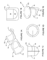
- Figures 1A to 1E illustrate a primary package 24.
- the primary package 24 is a cup or vessel formed by thermoforming a sheet of material, preferably paperboard.
- the primary package 24 is formed in two or more sections P1, P2, preferably two sections P1, P2.
- Each section P1, P2 comprises a first flange F1.
- the first flange F1 is provided for securing the sections P1, P2 of the primary package 24 together.
- each section of the primary package 24 comprises a part of a second flange F2.
- the second flange F2 facilitates securing a lid or cover to the primary package.
- the present invention may be utilised with primary packages which are formed as a unitary piece.
- the primary package 24 comprises sidewalls 14, 18 and a base wall 20; base wall 20 is optionally dome shaped.
- the two sections P1, P2 of the primary package 24 are hinged together by a hinge connection 19.
- the primary package 24 comprises an open end through which a product such as foodstuffs or beverages are loaded.
- FIG. 1 there is shown a secondary package and blank 110 for forming the secondary package.
- a combination of the secondary package with one or more primary packages 24 forms a combination package 140 according to a first embodiment of the present invention.
- the blank 110 comprises panels for forming a top panel 112, first side panel 114, base panel 116, second side panel 118 and a glue flap 120.
- the blank 110 is shaped and arranged to accommodate four primary packages 24 arranged in a two by two array; in alternative embodiments the blank 110 may be arranged to accommodate a different number of primary packages or articles and/or a different array configuration.
- the top panel 112 comprises four sections 112A, 112B, 112C, 112D, each section of which forms a lid of a respective primary package 24.
- the first section 112A is severable from each of second and third sections 112B and 112C by respective weakened lines of severance 117A, 113A.
- Second section 112B is severable from each of first and a fourth section 112A and 112D by respective weakened lines of severance 117A and 113B.
- Third section 112C is severable from fourth section 112D by weakened line of severance 117B.
- Top panel 112 is hinged to first side panel 114.
- First side panel 114 comprises a first part 114A and second part 114B which are separated from one another. In alternative embodiments, first part 114A and second part 114B may be coupled to one another by a weakened line of severance.
- the first part 114A is hinged to the top panel 112 by a fold line 115A, which extends at least partially along a side edge of third section 112C.
- the second part 114B is hinged to the top panel 112 by a fold line 115B which extends at least partially along a side edge of fourth section 112D.
- fold lines 115A and 115B may be continuous and/or may be formed from weakened lines of severance.
- the first side wall 114 is hinged to the base panel 116.
- the base panel 116 comprises a first component 116A and a second component 116B.
- the first and second components 116A, 116B are separate from one another; however it is envisaged that they could be coupled together by a weakened line of severance in alternative embodiments.
- Each of the first and second components 116A, 116B provide a foot or stabiliser for a pair of primary packages 24.
- the first and second components 116A, 116B are substantially the same structure and will be described by reference to second component 116B.
- Second component 116B comprises a series of panels 124, 126, 128, 130 joined one to the next in a linear series which extends along the tubular axis of the combination package 140.
- the first panel 124 is hingedly connected to second panel 126 along fold line 127; the second panel 126 is hingedly connected to the third panel 128 along fold line 129 and the third panel 128 is hingedly connected to fourth panel 130 along fold line 131.
- the second and third panels 126, 128 are coupled to the first side wall, in particular to second part 114B via riser panel 122.
- Second panel 126 is coupled to riser panel 122 via fold line 123B.
- Third panel 128 is coupled to riser panel 122 via fold line 123A.
- Riser panel 122 is coupled to second part 114B via fold line 121.
- Fold lines 123A and 123B are disposed so as to be divergent towards fold line 121 and are disposed at opposed ends of fold line 121.
- Fold lines 123A, 123B are convergent towards fold line 129.
- An arcuate cutline 125 or weakened line of severance is interposed between fold lines 123A, 123B such that fold lines 123A, 123B and cut line 125 together form a V shape which converges at fold line 129.
- a second riser panel 132 is disposed at the opposite end of second and third panels 126, 128.
- a weakened line of severance 135 bisects each of the first, second, third and fourth panels, 124, 126, 128, 130.
- a first slot S1 is disposed between riser panel 122 and weakened line 135, and a second slot S2 is disposed between weakened line 135 and riser panel 132.
- Third and fourth slots S3, S4 are provided on first part 116A.
- Each of slots S1 and S2 extend across the second and third panels 126, 128 parallel to the direction of the tubular axis.
- Base panel 116 is coupled to second side panel 118.
- Second side panel 118 comprises a first element 118A and a second element 118B coupled to respective ones of first or second components 116A, 116B forming base panel 116, by fold line 133.
- First and second elements 118A, 118B are separate from one another. It is envisaged that in alternative embodiments they may be unitary or coupled by a weakened line of severance.
- Second side panel 118 is coupled to glue panel 120.
- Glue panel 120 comprises glue flap 120A and glue flap 120B which are separate from one another.
- Glue flap 120A is coupled to first element 118A by fold line 111A and glue flap 120B is coupled to second element 118B by fold line 111B.
- the secondary package can be formed by a series of sequential folding operations in a straight line machine, so that the secondary package is not required to be rotated or inverted to complete its construction.
- the folding process is not limited to that described below and may be altered according to particular manufacturing requirements.
- the first and second components 116A, 116B are constructed such that second and third panels 126, 128 form inverted V shapes; riser panels 122 and 132 are folded out of the plane of the blank 110 to be disposed at an angle thereto.
- the second and third panels 126, 128 are folded upwardly out of the plane of the blank 110.
- First and fourth panels 124, 130 form a base upon which the secondary package may rest.
- a group of primary packages 24 are received on each of the first and second components 116A, 116B.
- Slots S1, S2 each receive a flange F1 of a primary package 24 which flange F1 extends downward of the base of the primary packages 24.
- the first and second side panels 114, 118 are folded about the sides of the group of primary packages 24.
- the top panel 112 is folded to overlay the open ends 9 of the primary packages 24.
- the primary packages 24 may be filled with a product prior to placement on the base panel 116 or prior to folding the top panel 112 about the open ends of the primary packages 24.
- Adhesive or sealant may be applied either to the flanges F2 or to the top panel 112 prior to folding the top panel 112 about the open ends 9 of the primary packages 24; in this way the top panel 112 can be secured or sealed to the primary packages 24.
- the glue panel 120 may then be folded about the top panel 112 to secure the panels of the blank in a tubular structure about the primary packages 24. In some embodiments the glue panel 120 may be folded about the primary packages 24 before folding the top panel 120.
- Figure 4 illustrates the assembled combination package 140.
- Each of the primary packages 24 may be separated from the combination package 140 by severing the respective severance lines 113A, 113B, 117A, 117B, 135 as shown in Figure 4 , where an individual primary package 24 has been separated from the remaining primary packages 24.
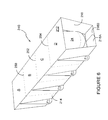
- Figure 5 illustrates a blank 210 for forming the combination package 240 illustrated in Figure 6 .
- Blank 210 comprises a top panel 212 first hinged to first side panel 214 along fold line 215 and to second side panel 218 along fold line 213.
- First side panel 214 is hinged to first base panel 216A along fold line 217.
- Second side panel 218 is hinged to second base panel 216B along fold line 211.
- First side panel 214 comprises four slots S1, S2, S3, S4 extending between the top panel 212 and the first base panel 216A.
- Second side panel 218 comprises four slots S1, S2, S3, S4 extending between top panels 212 and second base panel 216B. Slots S1, S2, S3, S4 in second side panel 218 are co-linear with slots S1, S2, S3, S4 in first side panel 214.
- Blank 210 comprises a first weakened line of severance 250 extending across the first base panel 216A, first side panel 214, top panel 212, second side panel 218 and second base panel 216B.
- First line of severance 250 is disposed between first slot S1 and second slot S2.
- a second line of severance 252 extends across blank 210 from a free edge of first base panel 216A to a free edge of second base panel 216B; second line of severance 252 is disposed between slots S2 and slots S3.
- a third weakened line of severance 254 extends across the blank 210 from a free edge of first base panel 216A to a free edge of second base panel 216B and is disposed between slots S3 and S4.
- the combination package 240 of Figure 6 is constructed by wrapping the blank 210 about a group of primary packages 24.
- the combination package 240 accommodates four primary packages 24 arranged in a four by one array.
- Top panel 212 provides a lid for open ends of each of the primary packages 24.
- the slots S1, S2, S3, S4 receive at least a portion of a flange F1 of a respective one of the primary packages 24.
- First and second base panels 216A, 216B are placed in overlapping relationship with one another and secured together using adhesive or a mechanical locking device.
- Each of the primary packages 24 may be separated from the combination package 240 by severing the respective one of the first, second and third weakened lines of severance 250, 252, 254.
- the primary package 24 may not comprise the first flange F1 in which case the slots S1, S2, S3, S4 may be omitted.
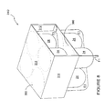
- the blank 310 comprises a series of panels hinged one to the next in a linear series and includes a top panel 314 hinged to a first side panel 312 on a first side edge and to a second side panel 316 on a second side edge.
- First side panel 312 is hinged to a glue flap 320.
- Second side panel 316 is hinged to base panel 318.
- Top panel 314 and base panel 318 each comprise four circularly shaped weakened lines of severance 360.
- Each of the weakened lines of severance 360 defines a respective portion of the top or base panels 314, 318, each of which forms a lid for a respective primary package 24.
- the weakened lines of severance 360 in each of the top and base panels 314, 318 are arranged in a two by two array.
- the combination package 340 is formed by grouping together four primary packages 24, filling the primary packages 24 with a product, and placing the base panel 318 over the open ends 9 of each of the primary packages 24 such that the weakened lines of severance 360 are in registry with outer periphery of the primary packages 24; which in the illustrated embodiment is defined by the circumferential edge of second flange F2.
- a second group of four primary packages 24, arranged in a two by two array, is placed upon the base panel 318 to form a second or upper tier of primary packages 24. They may be filled with a product prior to placement on base panel 318, or once the primary packages 24 are placed upon the base panel 318.
- the second side panel 316 is folded about the side of the group of primary packages 24.
- the top panel 314 is then folded to overlay the open ends of the upper tier of primary packages 24 such that the weakened lines of severance 360 are placed in registry with the open ends of the primary packages 24.
- the first side panel 312 is then folded about the opposing side of the group of primary packages 24.
- Glue flap 320 is then secured to a lowermost surface of the base panel 318.
- the size and shape of the panels and apertures may be adjusted to accommodate articles of differing size or shape.
- the primary packages may not be formed with a vertical flange.
- the secondary packages may be adapted to remove those features such as slots which are adapted to accommodate the vertical flanges.
- hinged connection should not be construed as necessarily referring to a single fold line only; indeed it is envisaged that hinged connection can be formed from one or more of the following: a short slit, a frangible line or a fold line without departing from the scope of the invention.
Landscapes
- Engineering & Computer Science (AREA)
- Mechanical Engineering (AREA)
- Packages (AREA)
Abstract
A combination package for a product, such as foodstuffs or beverages, includes at least one primary package in which naked product is directly contained. The at least one primary package includes a hollow structure having side walls and a pair of first and second opposed ends. The first end is closed by a base wall. The second end is open. The at least one primary package is placed in a secondary package such as a carton. The secondary package comprises a base wall, opposing side walls and a top wall. The top wall provides an end closure for the open end of the at least one primary package.
Description
- The present invention relates to a combination of a primary package and a secondary package and more specifically, but not exclusively, to a combination in which an end closure of at least one primary package is provided by the secondary package. The present invention also relates to a carton that provides a secondary package and a blank for forming the secondary package.
- In the field of packaging, it is often required to provide consumers with a package comprising multiple primary product containers (i.e., primary packages) contained in an outer container (i.e., a secondary package). Such packages, or multi-packs, are desirable for shipping and distribution and for display of promotional information. For cost and environmental considerations, such packages need to be formed from as little material as possible and cause as little wastage in the materials from which they are formed as possible. Another consideration is the strength of the packaging and its suitability for holding and transporting large weights of articles.
- It is therefore desirable to provide a carton which forms a secondary package, which can accommodate one or more primary packages.
- It is desirable for the carton to provide a portion which completes formation of one or more primary packages.
- The present invention seeks to overcome or at least mitigate the problems of the prior art.
- The term "primary package" as used herein refers to a primary container such as a cup, can, bottle, jar, carton, box, carrier, bag or any other container in which a naked product such as a foodstuff or beverage is directly received, such that such a naked product is in direct contact with the inside surface of the primary container.
- The term "secondary package", as used herein, refers to a secondary container such as a cup, can, jar, carton, box, carrier, bag or any other container in which one or more primary packages are received, such that the one or more primary packages are in direct contact with the inside surface of the secondary container.
- According to a first aspect of the present invention, there is provided a combination package for a product such as foodstuffs or beverages, wherein the combination package comprises at least one primary package containing a product such as a foodstuff or beverage. The at least one primary package comprises a hollow structure closed at one end thereof by a base wall and having side walls and an open end opposing the closed end, the at least one primary package being placed in a secondary package which comprises a base wall, opposing side walls and a top wall, the top wall of the secondary package providing an end closure for the open end of the at least one primary package.
- Preferably, the at least one primary package comprises two or more primary packages, and the secondary package comprises one or more severable connections at the top wall between the end closures of the two or more primary packages so as to allow an individual primary package to be separated from the remainder of the two or more primary packages.
- According to a second aspect of the present invention there is provided a package for a product such as foodstuffs or beverages wherein the package comprises a plurality of vessels containing the product, the vessels comprising a tubular structure closed at one end thereof by a base wall and having side walls and an open end opposing the first end for facilitating loading of product, the package further comprises a carton having a plurality of panels including a base wall, opposing side walls and a top wall, wherein the plurality of panels form a sleeve structure about the plurality of vessels and the top wall of the carton provides an end closure for the open end of each of the plurality of vessels.
- Preferably, the carton comprises one or more severable connections at the top wall between the end closures so as to allow an individual vessel to be separated from the package.
- According to a third aspect of the present invention there is provided a blank for forming a secondary package, comprising panels for forming side walls, a top wall and a base wall, the top wall being sized and arranged to form at least one lid of a primary package, for sealing a product within the primary package.
- Preferably, the at least one lid comprises two or more lids, wherein the top wall comprises at least one weakened line of severance which defines the two or more lids, each of the two or more lids being severable from the remainder of the two or more lids along the at least one weakened line of severance.
- Exemplary embodiments of the invention will now be described with reference to the accompanying drawings, in which:
- FIGURE 1A
- is a perspective view from above of an exemplary part-formed primary package for forming a combination package of the present invention;
- FIGURE 1B
- is a side view of an exemplary primary package for forming a combination package of the present invention;
- FIGURE 1C
- is an end view of the primary package of
Figure 1B ; - FIGURE 1D
- is a top view of the primary package of
Figure 1B ; - FIGURE 1E
- is a perspective view of the primary package of
Figure 1B ; - FIGURE 2
- is a plan view from above of a blank for forming a secondary package according to a first embodiment;
- FIGURE 3
- is a perspective view from above of a stage of assembly of the combination package according to the first embodiment;
- FIGURE 4
- is a perspective view from above of the combination package according to the first embodiment;
- FIGURE 5
- is a plan view from above of a blank of a secondary package for the combination package of a second embodiment;
- FIGURE 6
- is a perspective view from above of the combination package according to the second embodiment;
- FIGURE 7
- is a plan view from above of a blank for forming a secondary package according to a third embodiment; and
- FIGURE 8
- is a perspective view from above of a combination package according to the third embodiment.
- Detailed descriptions of specific embodiments of the combination packages, secondary packages, blanks for forming the secondary packages and primary packages are disclosed herein. It will be understood that the disclosed embodiments are merely examples of the way in which certain aspects of the invention can be implemented and do not represent an exhaustive list of all of the ways the invention may be embodied. Indeed, it will be understood that the combination packages, secondary packages, blanks for forming the secondary packages and primary packages described herein may be embodied in various and alternative forms. The Figures are not necessarily to scale, and some features may be exaggerated or minimised to show details of particular components. Well-known components, materials or methods are not necessarily described in great detail in order to avoid obscuring the present disclosure. Any specific structural and functional details disclosed herein are not to be interpreted as limiting, but merely as a basis for the claims and as a representative basis for teaching one skilled in the art to variously employ the invention.
-
Figures 1A to 1E illustrate aprimary package 24. Optionally, theprimary package 24 is a cup or vessel formed by thermoforming a sheet of material, preferably paperboard. Theprimary package 24 is formed in two or more sections P1, P2, preferably two sections P1, P2. Each section P1, P2 comprises a first flange F1. The first flange F1 is provided for securing the sections P1, P2 of theprimary package 24 together. - The method of forming the primary package and the primary package itself are the subject of co-pending European patent application to LeBras, application number
EP12160673.5 - Optionally, each section of the
primary package 24 comprises a part of a second flange F2. The second flange F2 facilitates securing a lid or cover to the primary package. - It is envisaged that the present invention may be utilised with primary packages which are formed as a unitary piece.
- The
primary package 24 comprises sidewalls 14, 18 and abase wall 20;base wall 20 is optionally dome shaped. - Preferably, the two sections P1, P2 of the
primary package 24 are hinged together by ahinge connection 19. - The
primary package 24 comprises an open end through which a product such as foodstuffs or beverages are loaded. - Turning now to
Figures 2 to 4 , there is shown a secondary package and blank 110 for forming the secondary package. A combination of the secondary package with one or moreprimary packages 24 forms acombination package 140 according to a first embodiment of the present invention. The blank 110 comprises panels for forming atop panel 112,first side panel 114,base panel 116,second side panel 118 and aglue flap 120. - In the illustrated embodiment in
Figures 2 to 4 , the blank 110 is shaped and arranged to accommodate fourprimary packages 24 arranged in a two by two array; in alternative embodiments the blank 110 may be arranged to accommodate a different number of primary packages or articles and/or a different array configuration. - The
top panel 112 comprises foursections primary package 24. Thefirst section 112A is severable from each of second andthird sections severance Second section 112B is severable from each of first and afourth section severance Third section 112C is severable fromfourth section 112D by weakened line ofseverance 117B.Top panel 112 is hinged tofirst side panel 114.First side panel 114 comprises afirst part 114A andsecond part 114B which are separated from one another. In alternative embodiments,first part 114A andsecond part 114B may be coupled to one another by a weakened line of severance. - The
first part 114A is hinged to thetop panel 112 by afold line 115A, which extends at least partially along a side edge ofthird section 112C. - The
second part 114B is hinged to thetop panel 112 by afold line 115B which extends at least partially along a side edge offourth section 112D. In alternative embodiments foldlines - The
first side wall 114 is hinged to thebase panel 116. - The
base panel 116 comprises afirst component 116A and asecond component 116B. The first andsecond components - Each of the first and
second components primary packages 24. The first andsecond components second component 116B. -
Second component 116B comprises a series ofpanels combination package 140. Thefirst panel 124 is hingedly connected tosecond panel 126 alongfold line 127; thesecond panel 126 is hingedly connected to thethird panel 128 alongfold line 129 and thethird panel 128 is hingedly connected tofourth panel 130 alongfold line 131. - The second and
third panels second part 114B viariser panel 122.Second panel 126 is coupled toriser panel 122 viafold line 123B.Third panel 128 is coupled toriser panel 122 viafold line 123A.Riser panel 122 is coupled tosecond part 114B viafold line 121. Foldlines fold line 121 and are disposed at opposed ends offold line 121. - Fold
lines fold line 129. Anarcuate cutline 125 or weakened line of severance is interposed betweenfold lines fold lines line 125 together form a V shape which converges atfold line 129. Asecond riser panel 132 is disposed at the opposite end of second andthird panels - A weakened line of
severance 135 bisects each of the first, second, third and fourth panels, 124, 126, 128, 130. A first slot S1 is disposed betweenriser panel 122 and weakenedline 135, and a second slot S2 is disposed between weakenedline 135 andriser panel 132. - Third and fourth slots S3, S4 are provided on
first part 116A. - Each of slots S1 and S2 extend across the second and
third panels Base panel 116 is coupled tosecond side panel 118.Second side panel 118 comprises afirst element 118A and asecond element 118B coupled to respective ones of first orsecond components base panel 116, byfold line 133. - First and
second elements -
Second side panel 118 is coupled toglue panel 120.Glue panel 120 comprisesglue flap 120A andglue flap 120B which are separate from one another.Glue flap 120A is coupled tofirst element 118A byfold line 111A andglue flap 120B is coupled tosecond element 118B byfold line 111B. - Turning now to the construction of the secondary package or carton as illustrated in
Figures 2 ,3 and4 , it is envisaged that the secondary package can be formed by a series of sequential folding operations in a straight line machine, so that the secondary package is not required to be rotated or inverted to complete its construction. The folding process is not limited to that described below and may be altered according to particular manufacturing requirements. - The first and
second components third panels riser panels third panels fourth panels - A group of
primary packages 24 are received on each of the first andsecond components primary package 24 which flange F1 extends downward of the base of theprimary packages 24. - The first and
second side panels primary packages 24. - The
top panel 112 is folded to overlay the open ends 9 of theprimary packages 24. Theprimary packages 24 may be filled with a product prior to placement on thebase panel 116 or prior to folding thetop panel 112 about the open ends of theprimary packages 24. - Adhesive or sealant may be applied either to the flanges F2 or to the
top panel 112 prior to folding thetop panel 112 about the open ends 9 of theprimary packages 24; in this way thetop panel 112 can be secured or sealed to the primary packages 24. - The
glue panel 120 may then be folded about thetop panel 112 to secure the panels of the blank in a tubular structure about the primary packages 24. In some embodiments theglue panel 120 may be folded about theprimary packages 24 before folding thetop panel 120. -
Figure 4 illustrates the assembledcombination package 140. Each of theprimary packages 24 may be separated from thecombination package 140 by severing therespective severance lines Figure 4 , where an individualprimary package 24 has been separated from the remainingprimary packages 24. - Referring now to
Figures 5 to 8 , there are shown alternative embodiments of the present invention. In the second and third illustrated embodiment, like numerals have, where possible, been used to denote like parts, albeit with the addition of the prefix "200" or "300" and so on to indicate that these features belong to the second embodiment. The alternative embodiments share many common features with the first embodiment and therefore only the differences from the embodiment illustrated inFigures 1 to 4 will be described in any greater detail. -
Figure 5 illustrates a blank 210 for forming thecombination package 240 illustrated inFigure 6 . -
Blank 210 comprises atop panel 212 first hinged tofirst side panel 214 alongfold line 215 and tosecond side panel 218 alongfold line 213.First side panel 214 is hinged tofirst base panel 216A alongfold line 217.Second side panel 218 is hinged tosecond base panel 216B alongfold line 211.First side panel 214 comprises four slots S1, S2, S3, S4 extending between thetop panel 212 and thefirst base panel 216A.Second side panel 218 comprises four slots S1, S2, S3, S4 extending betweentop panels 212 andsecond base panel 216B. Slots S1, S2, S3, S4 insecond side panel 218 are co-linear with slots S1, S2, S3, S4 infirst side panel 214. -
Blank 210 comprises a first weakened line ofseverance 250 extending across thefirst base panel 216A,first side panel 214,top panel 212,second side panel 218 andsecond base panel 216B. First line ofseverance 250 is disposed between first slot S1 and second slot S2. - A second line of
severance 252 extends across blank 210 from a free edge offirst base panel 216A to a free edge ofsecond base panel 216B; second line ofseverance 252 is disposed between slots S2 and slots S3. - A third weakened line of
severance 254 extends across the blank 210 from a free edge offirst base panel 216A to a free edge ofsecond base panel 216B and is disposed between slots S3 and S4. - First, second and third weakened lines of
severance combination package 240 into four sections A, B, C, D as can be seen inFigure 6 . - The
combination package 240 ofFigure 6 is constructed by wrapping the blank 210 about a group ofprimary packages 24. In the illustrated embodiment thecombination package 240 accommodates fourprimary packages 24 arranged in a four by one array.Top panel 212 provides a lid for open ends of each of theprimary packages 24. The slots S1, S2, S3, S4 receive at least a portion of a flange F1 of a respective one of theprimary packages 24. - First and
second base panels - Each of the
primary packages 24 may be separated from thecombination package 240 by severing the respective one of the first, second and third weakened lines ofseverance - It is envisaged that the
primary package 24 may not comprise the first flange F1 in which case the slots S1, S2, S3, S4 may be omitted. - Referring now to
Figures 7 and8 there is shown a blank 310 for forming acombination package 340. The blank 310 comprises a series of panels hinged one to the next in a linear series and includes atop panel 314 hinged to afirst side panel 312 on a first side edge and to asecond side panel 316 on a second side edge.First side panel 312 is hinged to aglue flap 320.Second side panel 316 is hinged tobase panel 318. -
Top panel 314 andbase panel 318 each comprise four circularly shaped weakened lines ofseverance 360. - Each of the weakened lines of
severance 360 defines a respective portion of the top orbase panels primary package 24. The weakened lines ofseverance 360 in each of the top andbase panels - The
combination package 340 is formed by grouping together fourprimary packages 24, filling theprimary packages 24 with a product, and placing thebase panel 318 over the open ends 9 of each of theprimary packages 24 such that the weakened lines ofseverance 360 are in registry with outer periphery of theprimary packages 24; which in the illustrated embodiment is defined by the circumferential edge of second flange F2. A second group of fourprimary packages 24, arranged in a two by two array, is placed upon thebase panel 318 to form a second or upper tier ofprimary packages 24. They may be filled with a product prior to placement onbase panel 318, or once theprimary packages 24 are placed upon thebase panel 318. - The
second side panel 316 is folded about the side of the group ofprimary packages 24. Thetop panel 314 is then folded to overlay the open ends of the upper tier ofprimary packages 24 such that the weakened lines ofseverance 360 are placed in registry with the open ends of theprimary packages 24. Thefirst side panel 312 is then folded about the opposing side of the group ofprimary packages 24.Glue flap 320 is then secured to a lowermost surface of thebase panel 318. - It can be appreciated that various changes may be made within the scope of the present invention. For example, the size and shape of the panels and apertures may be adjusted to accommodate articles of differing size or shape. In other embodiments of the invention it is envisaged that the primary packages may not be formed with a vertical flange. In such cases, the secondary packages may be adapted to remove those features such as slots which are adapted to accommodate the vertical flanges.
- It will be recognised that as used herein, directional references such as "top", "bottom", "front", "back", "end", "side", "inner", "outer", "upper" and "lower" do not limit the respective panels to such orientation, but merely serve to distinguish these panels from one another. Any reference to hinged connection should not be construed as necessarily referring to a single fold line only; indeed it is envisaged that hinged connection can be formed from one or more of the following: a short slit, a frangible line or a fold line without departing from the scope of the invention.
Claims (6)
- A combination comprising at least one primary package containing a product such as a foodstuff or beverage, the at least one primary package comprising a hollow structure closed at one end thereof by a base wall and having side walls and an open end opposing the closed end, the at least one primary package being placed in a secondary package which comprises a base wall, opposing side walls and a top wall, said top wall of the secondary package providing an end closure for the open end of the at least one primary package.
- A combination according to claim 1 wherein the at least one primary package comprises two or more primary packages, and the secondary package comprises one or more severable connections at the top wall between the end closures of the two or more primary packages so as to allow an individual primary package to be separated from the remainder of the two or more primary packages.
- A package for a product such as foodstuffs or beverages wherein the package comprises a plurality of vessels containing the product, the vessels comprising a tubular structure closed at one end thereof by a base wall and having side walls and an open end opposing the first end for facilitating loading of the product, the package further comprising a carton having a plurality of panels including a base wall, opposing side walls and a top wall, wherein the plurality of panels form a sleeve structure about the plurality of vessels and said top wall of the carton provides an end closure for the open end of each of said plurality of vessels.
- A package according to claim 3 wherein the carton comprises one or more severable connections at the top wall between the end closures so as to allow an individual vessel to be separated from the package.
- A blank for forming a secondary package comprising panels for forming side walls, a top wall and a base wall, the top wall being sized and arranged to form at least one lid of a primary package, for sealing a product within the primary package.
- A blank according to claim 5 wherein said at least one lid comprises two or more lids wherein the top wall comprises at least one weakened line of severance which defines the two or more lids, each of the two or more lids being severable from the remainder of the two or more lids along the at least one weakened line of severance.
Applications Claiming Priority (2)
| Application Number | Priority Date | Filing Date | Title |
|---|---|---|---|
| GBGB1104828.7A GB201104828D0 (en) | 2011-03-22 | 2011-03-22 | Package and method of forming the same |
| GBGB1104827.9A GB201104827D0 (en) | 2011-03-22 | 2011-03-22 | Primary and secondary package combination the secondary package and blank for forming the secondary package |
Publications (1)
| Publication Number | Publication Date |
|---|---|
| EP2502839A1 true EP2502839A1 (en) | 2012-09-26 |
Family
ID=45936876
Family Applications (1)
| Application Number | Title | Priority Date | Filing Date |
|---|---|---|---|
| EP12160696A Withdrawn EP2502839A1 (en) | 2011-03-22 | 2012-03-22 | Primary and secondary package combination, the secondary package and blank for forming the secondary package |
Country Status (1)
| Country | Link |
|---|---|
| EP (1) | EP2502839A1 (en) |
Citations (3)
| Publication number | Priority date | Publication date | Assignee | Title |
|---|---|---|---|---|
| US3168193A (en) * | 1962-08-20 | 1965-02-02 | Phillips Petroleum Co | Formed container multipack |
| US3286909A (en) * | 1963-08-14 | 1966-11-22 | Anaconda Aluminum Co | Container |
| FR2444624A1 (en) * | 1978-12-18 | 1980-07-18 | Etu Tech Realisa Appliq Centre | Channel profiles - for gripping thermoplastic containers for display and manipulation in gps. |
-
2012
- 2012-03-22 EP EP12160696A patent/EP2502839A1/en not_active Withdrawn
Patent Citations (3)
| Publication number | Priority date | Publication date | Assignee | Title |
|---|---|---|---|---|
| US3168193A (en) * | 1962-08-20 | 1965-02-02 | Phillips Petroleum Co | Formed container multipack |
| US3286909A (en) * | 1963-08-14 | 1966-11-22 | Anaconda Aluminum Co | Container |
| FR2444624A1 (en) * | 1978-12-18 | 1980-07-18 | Etu Tech Realisa Appliq Centre | Channel profiles - for gripping thermoplastic containers for display and manipulation in gps. |
Similar Documents
| Publication | Publication Date | Title |
|---|---|---|
| US10569947B2 (en) | Carton and carton blank and a handle structure therefor | |
| CN101395070B (en) | Package for containers | |
| KR101562719B1 (en) | Package for containers | |
| CN103717506B (en) | packaging for containers | |
| US10301091B2 (en) | Carton and blank therefor | |
| US20110253587A1 (en) | Carton tray | |
| US9493268B2 (en) | Package with strap handle | |
| US20240002122A1 (en) | Carton and blank therefor | |
| US9604768B2 (en) | Carton and carton blank | |
| CN102905988A (en) | packaging for containers | |
| US11932472B2 (en) | Carton and blank therefor | |
| US10479578B2 (en) | Basket style carrier and blank therefor | |
| AU2013266528B2 (en) | Carton and carton blank | |
| US20160130060A1 (en) | Carton and carton blank | |
| EP3222552B1 (en) | Carton and blank therefor | |
| US20100288657A1 (en) | Carton Tray | |
| US11891226B2 (en) | Basket style carrier, shipping carton and package system | |
| AU2017273420A1 (en) | Carton and blank therefor | |
| US20170313469A1 (en) | Carton and blank therefor | |
| US10279951B2 (en) | Carton and carton blank | |
| US12617595B2 (en) | Sleeve for holding containers | |
| WO2016054466A1 (en) | Carton and carton blank | |
| US20140373486A1 (en) | Carton, carton blank and method of forming a loaded carton | |
| EP2502836A1 (en) | Carton and blank for forming a package | |
| WO2012071247A2 (en) | Carton and blank therefor |
Legal Events
| Date | Code | Title | Description |
|---|---|---|---|
| PUAI | Public reference made under article 153(3) epc to a published international application that has entered the european phase |
Free format text: ORIGINAL CODE: 0009012 |
|
| 17P | Request for examination filed |
Effective date: 20120322 |
|
| AK | Designated contracting states |
Kind code of ref document: A1 Designated state(s): AL AT BE BG CH CY CZ DE DK EE ES FI FR GB GR HR HU IE IS IT LI LT LU LV MC MK MT NL NO PL PT RO RS SE SI SK SM TR |
|
| AX | Request for extension of the european patent |
Extension state: BA ME |
|
| STAA | Information on the status of an ep patent application or granted ep patent |
Free format text: STATUS: THE APPLICATION IS DEEMED TO BE WITHDRAWN |
|
| 18D | Application deemed to be withdrawn |
Effective date: 20130327 |