EP2502836A1 - Carton and blank for forming a package - Google Patents
Carton and blank for forming a package Download PDFInfo
- Publication number
- EP2502836A1 EP2502836A1 EP12160685A EP12160685A EP2502836A1 EP 2502836 A1 EP2502836 A1 EP 2502836A1 EP 12160685 A EP12160685 A EP 12160685A EP 12160685 A EP12160685 A EP 12160685A EP 2502836 A1 EP2502836 A1 EP 2502836A1
- Authority
- EP
- European Patent Office
- Prior art keywords
- article
- package
- flange
- panel
- carton
- Prior art date
- Legal status (The legal status is an assumption and is not a legal conclusion. Google has not performed a legal analysis and makes no representation as to the accuracy of the status listed.)
- Withdrawn
Links
- 239000003381 stabilizer Substances 0.000 claims abstract description 24
- 239000003292 glue Substances 0.000 description 16
- 238000000034 method Methods 0.000 description 8
- 239000000853 adhesive Substances 0.000 description 7
- 230000001070 adhesive effect Effects 0.000 description 7
- 239000000463 material Substances 0.000 description 5
- 238000004806 packaging method and process Methods 0.000 description 3
- 235000013361 beverage Nutrition 0.000 description 2
- 238000010276 construction Methods 0.000 description 2
- 238000004026 adhesive bonding Methods 0.000 description 1
- 239000000969 carrier Substances 0.000 description 1
- 230000000295 complement effect Effects 0.000 description 1
- 238000009826 distribution Methods 0.000 description 1
- 230000007613 environmental effect Effects 0.000 description 1
- 238000004519 manufacturing process Methods 0.000 description 1
- 239000011087 paperboard Substances 0.000 description 1
- 230000001737 promoting effect Effects 0.000 description 1
- 238000007789 sealing Methods 0.000 description 1
- 238000003856 thermoforming Methods 0.000 description 1
Images




Classifications
-
- B—PERFORMING OPERATIONS; TRANSPORTING
- B65—CONVEYING; PACKING; STORING; HANDLING THIN OR FILAMENTARY MATERIAL
- B65D—CONTAINERS FOR STORAGE OR TRANSPORT OF ARTICLES OR MATERIALS, e.g. BAGS, BARRELS, BOTTLES, BOXES, CANS, CARTONS, CRATES, DRUMS, JARS, TANKS, HOPPERS, FORWARDING CONTAINERS; ACCESSORIES, CLOSURES, OR FITTINGS THEREFOR; PACKAGING ELEMENTS; PACKAGES
- B65D71/00—Bundles of articles held together by packaging elements for convenience of storage or transport, e.g. portable segregating carrier for plural receptacles such as beer cans or pop bottles; Bales of material
- B65D71/06—Packaging elements holding or encircling completely or almost completely the bundle of articles, e.g. wrappers
- B65D71/12—Packaging elements holding or encircling completely or almost completely the bundle of articles, e.g. wrappers the packaging elements, e.g. wrappers being formed by folding a single blank
- B65D71/14—Packaging elements holding or encircling completely or almost completely the bundle of articles, e.g. wrappers the packaging elements, e.g. wrappers being formed by folding a single blank having the shape of a tube, without, or not being characterised by, end walls
- B65D71/16—Packaging elements holding or encircling completely or almost completely the bundle of articles, e.g. wrappers the packaging elements, e.g. wrappers being formed by folding a single blank having the shape of a tube, without, or not being characterised by, end walls with article-locating elements
- B65D71/22—Openings or windows formed in the side walls
-
- B—PERFORMING OPERATIONS; TRANSPORTING
- B65—CONVEYING; PACKING; STORING; HANDLING THIN OR FILAMENTARY MATERIAL
- B65D—CONTAINERS FOR STORAGE OR TRANSPORT OF ARTICLES OR MATERIALS, e.g. BAGS, BARRELS, BOTTLES, BOXES, CANS, CARTONS, CRATES, DRUMS, JARS, TANKS, HOPPERS, FORWARDING CONTAINERS; ACCESSORIES, CLOSURES, OR FITTINGS THEREFOR; PACKAGING ELEMENTS; PACKAGES
- B65D1/00—Rigid or semi-rigid containers having bodies formed in one piece, e.g. by casting metallic material, by moulding plastics, by blowing vitreous material, by throwing ceramic material, by moulding pulped fibrous material or by deep-drawing operations performed on sheet material
- B65D1/22—Boxes or like containers with side walls of substantial depth for enclosing contents
- B65D1/26—Thin-walled containers, e.g. formed by deep-drawing operations
-
- B—PERFORMING OPERATIONS; TRANSPORTING
- B65—CONVEYING; PACKING; STORING; HANDLING THIN OR FILAMENTARY MATERIAL
- B65D—CONTAINERS FOR STORAGE OR TRANSPORT OF ARTICLES OR MATERIALS, e.g. BAGS, BARRELS, BOTTLES, BOXES, CANS, CARTONS, CRATES, DRUMS, JARS, TANKS, HOPPERS, FORWARDING CONTAINERS; ACCESSORIES, CLOSURES, OR FITTINGS THEREFOR; PACKAGING ELEMENTS; PACKAGES
- B65D1/00—Rigid or semi-rigid containers having bodies formed in one piece, e.g. by casting metallic material, by moulding plastics, by blowing vitreous material, by throwing ceramic material, by moulding pulped fibrous material or by deep-drawing operations performed on sheet material
- B65D1/22—Boxes or like containers with side walls of substantial depth for enclosing contents
- B65D1/26—Thin-walled containers, e.g. formed by deep-drawing operations
- B65D1/30—Groups of containers joined together end-to-end or side-by-side
-
- B—PERFORMING OPERATIONS; TRANSPORTING
- B65—CONVEYING; PACKING; STORING; HANDLING THIN OR FILAMENTARY MATERIAL
- B65D—CONTAINERS FOR STORAGE OR TRANSPORT OF ARTICLES OR MATERIALS, e.g. BAGS, BARRELS, BOTTLES, BOXES, CANS, CARTONS, CRATES, DRUMS, JARS, TANKS, HOPPERS, FORWARDING CONTAINERS; ACCESSORIES, CLOSURES, OR FITTINGS THEREFOR; PACKAGING ELEMENTS; PACKAGES
- B65D25/00—Details of other kinds or types of rigid or semi-rigid containers
- B65D25/20—External fittings
- B65D25/24—External fittings for spacing bases of containers from supporting surfaces, e.g. legs
-
- B—PERFORMING OPERATIONS; TRANSPORTING
- B65—CONVEYING; PACKING; STORING; HANDLING THIN OR FILAMENTARY MATERIAL
- B65D—CONTAINERS FOR STORAGE OR TRANSPORT OF ARTICLES OR MATERIALS, e.g. BAGS, BARRELS, BOTTLES, BOXES, CANS, CARTONS, CRATES, DRUMS, JARS, TANKS, HOPPERS, FORWARDING CONTAINERS; ACCESSORIES, CLOSURES, OR FITTINGS THEREFOR; PACKAGING ELEMENTS; PACKAGES
- B65D5/00—Rigid or semi-rigid containers of polygonal cross-section, e.g. boxes, cartons or trays, formed by folding or erecting one or more blanks made of paper
- B65D5/42—Details of containers or of foldable or erectable container blanks
- B65D5/44—Integral, inserted or attached portions forming internal or external fittings
- B65D5/50—Internal supporting or protecting elements for contents
- B65D5/5002—Integral elements for containers having tubular body walls
- B65D5/5019—Integral elements for containers having tubular body walls formed by openings in the body walls
-
- B—PERFORMING OPERATIONS; TRANSPORTING
- B65—CONVEYING; PACKING; STORING; HANDLING THIN OR FILAMENTARY MATERIAL
- B65D—CONTAINERS FOR STORAGE OR TRANSPORT OF ARTICLES OR MATERIALS, e.g. BAGS, BARRELS, BOTTLES, BOXES, CANS, CARTONS, CRATES, DRUMS, JARS, TANKS, HOPPERS, FORWARDING CONTAINERS; ACCESSORIES, CLOSURES, OR FITTINGS THEREFOR; PACKAGING ELEMENTS; PACKAGES
- B65D2571/00—Bundles of articles held together by packaging elements for convenience of storage or transport, e.g. portable segregating carrier for plural receptacles such as beer cans, pop bottles; Bales of material
- B65D2571/00123—Bundling wrappers or trays
- B65D2571/00129—Wrapper locking means
- B65D2571/00135—Wrapper locking means integral with the wrapper
- B65D2571/00141—Wrapper locking means integral with the wrapper glued
-
- B—PERFORMING OPERATIONS; TRANSPORTING
- B65—CONVEYING; PACKING; STORING; HANDLING THIN OR FILAMENTARY MATERIAL
- B65D—CONTAINERS FOR STORAGE OR TRANSPORT OF ARTICLES OR MATERIALS, e.g. BAGS, BARRELS, BOTTLES, BOXES, CANS, CARTONS, CRATES, DRUMS, JARS, TANKS, HOPPERS, FORWARDING CONTAINERS; ACCESSORIES, CLOSURES, OR FITTINGS THEREFOR; PACKAGING ELEMENTS; PACKAGES
- B65D2571/00—Bundles of articles held together by packaging elements for convenience of storage or transport, e.g. portable segregating carrier for plural receptacles such as beer cans, pop bottles; Bales of material
- B65D2571/00123—Bundling wrappers or trays
- B65D2571/00246—Locating elements for the contents
- B65D2571/00253—Locating elements for the contents integral with the wrapper
- B65D2571/00283—Openings in at least a side wall
-
- B—PERFORMING OPERATIONS; TRANSPORTING
- B65—CONVEYING; PACKING; STORING; HANDLING THIN OR FILAMENTARY MATERIAL
- B65D—CONTAINERS FOR STORAGE OR TRANSPORT OF ARTICLES OR MATERIALS, e.g. BAGS, BARRELS, BOTTLES, BOXES, CANS, CARTONS, CRATES, DRUMS, JARS, TANKS, HOPPERS, FORWARDING CONTAINERS; ACCESSORIES, CLOSURES, OR FITTINGS THEREFOR; PACKAGING ELEMENTS; PACKAGES
- B65D2571/00—Bundles of articles held together by packaging elements for convenience of storage or transport, e.g. portable segregating carrier for plural receptacles such as beer cans, pop bottles; Bales of material
- B65D2571/00123—Bundling wrappers or trays
- B65D2571/00246—Locating elements for the contents
- B65D2571/00253—Locating elements for the contents integral with the wrapper
- B65D2571/0029—Openings in top or bottom walls
-
- B—PERFORMING OPERATIONS; TRANSPORTING
- B65—CONVEYING; PACKING; STORING; HANDLING THIN OR FILAMENTARY MATERIAL
- B65D—CONTAINERS FOR STORAGE OR TRANSPORT OF ARTICLES OR MATERIALS, e.g. BAGS, BARRELS, BOTTLES, BOXES, CANS, CARTONS, CRATES, DRUMS, JARS, TANKS, HOPPERS, FORWARDING CONTAINERS; ACCESSORIES, CLOSURES, OR FITTINGS THEREFOR; PACKAGING ELEMENTS; PACKAGES
- B65D2571/00—Bundles of articles held together by packaging elements for convenience of storage or transport, e.g. portable segregating carrier for plural receptacles such as beer cans, pop bottles; Bales of material
- B65D2571/00123—Bundling wrappers or trays
- B65D2571/00648—Elements used to form the wrapper
- B65D2571/00654—Blanks
- B65D2571/0066—Blanks formed from one single sheet
-
- B—PERFORMING OPERATIONS; TRANSPORTING
- B65—CONVEYING; PACKING; STORING; HANDLING THIN OR FILAMENTARY MATERIAL
- B65D—CONTAINERS FOR STORAGE OR TRANSPORT OF ARTICLES OR MATERIALS, e.g. BAGS, BARRELS, BOTTLES, BOXES, CANS, CARTONS, CRATES, DRUMS, JARS, TANKS, HOPPERS, FORWARDING CONTAINERS; ACCESSORIES, CLOSURES, OR FITTINGS THEREFOR; PACKAGING ELEMENTS; PACKAGES
- B65D2571/00—Bundles of articles held together by packaging elements for convenience of storage or transport, e.g. portable segregating carrier for plural receptacles such as beer cans, pop bottles; Bales of material
- B65D2571/00123—Bundling wrappers or trays
- B65D2571/00709—Shape of the formed wrapper, i.e. shape of each formed element if the wrapper is made from more than one element
- B65D2571/00716—Shape of the formed wrapper, i.e. shape of each formed element if the wrapper is made from more than one element tubular without end walls
-
- B—PERFORMING OPERATIONS; TRANSPORTING
- B65—CONVEYING; PACKING; STORING; HANDLING THIN OR FILAMENTARY MATERIAL
- B65D—CONTAINERS FOR STORAGE OR TRANSPORT OF ARTICLES OR MATERIALS, e.g. BAGS, BARRELS, BOTTLES, BOXES, CANS, CARTONS, CRATES, DRUMS, JARS, TANKS, HOPPERS, FORWARDING CONTAINERS; ACCESSORIES, CLOSURES, OR FITTINGS THEREFOR; PACKAGING ELEMENTS; PACKAGES
- B65D2571/00—Bundles of articles held together by packaging elements for convenience of storage or transport, e.g. portable segregating carrier for plural receptacles such as beer cans, pop bottles; Bales of material
- B65D2571/00123—Bundling wrappers or trays
- B65D2571/00833—Other details of wrappers
- B65D2571/00864—Lines of weakness for separating into subgroups
-
- B—PERFORMING OPERATIONS; TRANSPORTING
- B65—CONVEYING; PACKING; STORING; HANDLING THIN OR FILAMENTARY MATERIAL
- B65D—CONTAINERS FOR STORAGE OR TRANSPORT OF ARTICLES OR MATERIALS, e.g. BAGS, BARRELS, BOTTLES, BOXES, CANS, CARTONS, CRATES, DRUMS, JARS, TANKS, HOPPERS, FORWARDING CONTAINERS; ACCESSORIES, CLOSURES, OR FITTINGS THEREFOR; PACKAGING ELEMENTS; PACKAGES
- B65D2571/00—Bundles of articles held together by packaging elements for convenience of storage or transport, e.g. portable segregating carrier for plural receptacles such as beer cans, pop bottles; Bales of material
- B65D2571/00123—Bundling wrappers or trays
- B65D2571/00833—Other details of wrappers
- B65D2571/00882—Supporting members
Definitions
- the present invention relates to a package for holding one or more articles more specifically, but not exclusively, to packaging articles having a vertical flange.
- Co-pending European Patent Application EP12160673.5 to LeBras entitled “Package and Method of Forming Same” filed on the same day as the present application, by the same applicant and which co-pending application claims priority to GB 1104828.7 , the contents of which are incorporated herein, directed to a package and method for forming the same, discloses a method of forming a primary package for holding a product such as foodstuffs or beverages.
- the package formed comprises a flange which extends outwardly from the walls of the primary package.
- the present invention seeks to overcome or at least mitigate the problems of the prior art.
- a package comprising at least one article, which comprises a flange extending outwardly from a base thereof, wherein the package further comprises a carton that includes one or more panels forming a foot or stabiliser for the at least one article and a connector for connecting the foot or stabiliser with the at least one article via the flange of the at least one article.
- a package comprising a carton and two or more articles, each of the two or more articles comprising a flange extending outwardly from a base thereof wherein the carton comprises two or more apertures, each of which receives a respective one of said two or more articles, wherein the carton further comprises a locating device which receives the flange of the each article so that each article takes a predetermined orientation with respect to the other articles, and wherein the two or more articles are arranged such that the flange of the two or more articles together form a stable base of the package.
- the at least one article or the each article defines a tubular axis
- the flange of the at least one article or the each article extends from at least a base wall of the at least one article or the each article along the tubular axis.
- the locating device comprises a slot formed in a panel of the carton.
- the foot or stabiliser may be deployed in a first position and stowed in a second position.
- a package comprising at least one article which comprises a flange extending outwardly therefrom, and a carton having a slot for receiving the flange of the at least one article, the slot being defined in or between one or more panels of the carton.
- a package comprising at least one article, which comprises a flange extending outwardly therefrom, and a carton having at least one wall panel, wherein the at least one wall panel comprises a recess shaped to accommodate at least a portion of the at least one article, and wherein said at least one wall panel is secured to the flange of the at least one article, the carton comprising at least one foot panel coupled to the at least one wall panel.
- a package comprising a plurality of articles, each of which articles comprises a flange standing outwardly from a base thereof, each of the flanges being coupled to one or more foot panels which can be folded into overlapping relationship with the each flange, the each flange and the foot panels being received in a respective slot defined in one or more panels of a carton.
- Figures 1A to 1E illustrate a primary container 24.
- the primary container 24 is formed by thermoforming a sheet of material, preferably paperboard; the primary container 24 is formed in two or more sections P1, P2, preferably two sections P1, P2.
- Each section P1, P2 comprises a first flange F1.
- the first flange F1 is provided for securing the sections P1, P2 of the container 24 together.
- the method of forming the primary package or container 24 and the primary package 24 itself are the subject of co-pending European patent application number EP12160673.5 to LeBras entitled “Package and Method of Forming Same” filed on the same day as the present application by the same applicant, the contents of which are incorporated herein, in particular the materials used to form the container 24, and the method of forming of the package in two or more sections.
- each section P1, P2 of the container 24 comprises a part of a second flange F2.
- the second flange F2 facilitates securing a lid or cover L best shown in Figure 4 to the primary package 24.
- primary containers 24 which are formed as a unitary piece, which unitary piece is formed with a flange.
- the primary container 24 comprises side walls 14, 18 and a base wall 20; base wall 20 is optionally dome shaped.
- the two sections P1, P2 of the container 24 are hinged together by a hinge connection 19.
- the container 24 comprises an open end through which a product such as foodstuffs or beverages are loaded.
- FIG. 2 to 5 there is shown a carton 140 and blank 110 for forming the carton 140, which carton 140 forms a package P according to a first embodiment of the present invention.
- the blank 110 comprises panels for forming a top panel 112, first side panel 114, base panel 116 and second side panel 118 and a glue flap 120.
- the blank 110 is shaped and arranged to accommodate four containers 24 arranged in a two by two array; in alternative embodiments the blank 110 may be arranged to accommodate a different number of containers or articles and/or a different array configuration.
- the top panel 112 comprises four sections 112A, 112B, 112C, 112D, each section of which forms a lid of a respective container 24.
- the first section 112A is severable from each of second and third sections 112B and 112C by respective weakened lines of severance 117A, 113A.
- Second section 112B is severable from each of first and a fourth section 112A and 112D by respective weakened lines of severance 117A and 113B.
- Third section 112C is severable from fourth section 112D by weakened line of severance 117B.
- Top panel 112 is hinged to first side panel 114.
- First side panel 114 comprises a first part 114A and a second part 114B which are separated from one another. In alternative embodiments, first part 114A and second part 114B may be coupled to one another by a weakened line of severance.
- the first part 114A is hinged to the top panel 112 by a fold line 115A, which extends at least partially along a side edge of third section 112C.
- the second part 114B is hinged to the top panel 112 by a fold line 115B which extends at least partially along a side edge of fourth section 112D.
- fold lines 115A and 115B may be continuous and/or may be formed from weakened lines of severance.
- the first side wall 114 is hinged to the base panel 116.
- the base panel 116 comprises a first component 116A and a second component 116B.
- the first and second components 116A, 116B are separate from one another; however, it is envisaged that they could be coupled together by a weakened line of severance in alternative embodiments.
- Each of the first and second components 116A, 116B provides a foot or stabiliser for a pair of containers 24.
- the first and second components 116A, 116B are substantially the same structure and will be described by reference to second part 116B.
- Second part 116B comprises a series of panels 124, 126, 128, 130 joined one to the next in a linear series which extends along the tubular axis of the package P.
- the first panel 124 is hingedly connected to second panel 126 along fold line 127; the second panel is hingedly connected to the third panel 128 along fold line 129 and the third panel is hingedly connected to fourth panel along fold line 131.
- the second and third panels 126, 128 are coupled to the first side wall 114, in particular to second part 114B via riser panel 122.
- Second panel 126 is coupled to riser panel 122 via fold line 123B.
- Third panel 128 is coupled to riser panel 122 via fold line 123A.
- Riser panel 122 is coupled to second part 114B via fold line 121.
- Fold lines 123A and 123B are disposed so as to be divergent towards fold line 121 and are disposed at opposed ends of fold line 121.
- Fold lines 123A, 123B are convergent towards fold line 129.
- An arcuate cutline 125 or weakened line of severance is interposed between fold lines 123A, 123B such that fold lines 123A, 123B and cut line 125 together form a V shape which converges at fold line 129.
- a second riser panel 132 is disposed at the opposite end of second and third panels 126, 128.
- a weakened line of severance 135 bisects each of the first, second, third and fourth panels, 124, 126, 128, 130.
- a first slot S1 is disposed between riser panel 122 and weakened line 135.
- a second slot S2 is disposed between riser panel 132 and weakened line 135.
- Third and fourth slots S3, S4 are similarly formed in second component 116B.
- Each of slots S1 and S2 extends across the second and third panels 126, 128 parallel to the direction of the tubular axis.
- Base panel 116 is coupled to second side panel 118.
- Second side panel 118 comprises a first element 118A and a second element 118B coupled to respective ones of the first and second components 116A, 116B of the base panel 116, by fold line 133.
- First and second elements 118A, 118B are separate from one another. It is envisaged that in alternative embodiments they may be unitary or coupled by a weakened line of severance.
- Second side panel 118 is coupled to glue panel 120.
- Glue panel 120 comprises glue flap 120A and glue flap 120B which are separate from one another.
- Glue flap 120A is coupled to first element 118A by fold line 111A and glue flap 120B is coupled to second element 118B by fold line 111B.
- the carton can be formed by a series of sequential folding operations in a straight line machine so that the carton is not required to be rotated or inverted to complete its construction.
- the folding process is not limited to that described below and may be altered according to particular manufacturing requirements.
- the base panels 116A, 116B are constructed such that second and third panels 126, 128 form inverted V shapes.
- Riser panels 122 and 132 are folded out of the plane of the blank 110 to be disposed at an angle thereto.
- the second and third panels 126, 128 are folded upwardly out of the plane of the blank 110.
- First and fourth panels 124, 130 form a base upon which the carton 140 may rest, and form part of a base structure 180 together with second and third panels 126, 128 which support the containers 24.
- a group of containers 24 are received on each of the first and second components 116A, 116B.
- Slots S1, S2 each receive a first flange F1 of a container 24 which first flange F1 extends downward of the base of the containers 24.
- the first and second side panels 114, 118 are folded about the sides of the group of containers 24.
- the top panel 112 is folded to overlay the group of containers 24.
- the containers 24 may be filled with a product prior to placement on the base panel 116 or prior to folding the top panel 112 about the containers 24. Lids L are applied to the container 24.
- Adhesive may be applied either to the second flanges F2 or to the lid L prior to sealing of the open ends of the containers 24.
- the top panel 112 can be secured to the lids L of the containers 24.
- top panel 112 may form the lid of each of the containers 24.
- the glue panel 120 may then be folded about the top panel 112 to secure the panels in a tubular structure about the containers 24. In some embodiments the glue panel 120 may be folded about the containers 24 before folding the top panel 112.
- Figure 4 illustrates the assembled package P holding each of the containers 24.
- the containers 24 may be separated from the package P by severing the respective severance lines 113A, 113B, 117A, 117B, 135 as shown in Figure 6 , where an individual container 24 has been separated from the remaining containers 24.
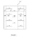
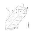
- Figure 7 illustrates a blank 210 for forming the package 240 illustrated in Figure 8 .
- Blank 210 comprises a top panel 212 first hinged to first side panel 214 along fold line 215 and to second side panel 218 along fold line 213.
- First side panel 214 is hinged to first base panel 216A along fold line 217.
- Second side panel 218 is hinged to second base panel 216B along fold line 211.
- First side panel 214 comprises four slots S1, S2, S3, S4 extending between the top panel 212 and the first base panel 216A.
- Second side panel 218 comprises four slots S1, S2, S3, S4 extending between top panels 212 and second base panel 216B. Slots S1, S2, S3, S4 in second side panel 218 are co-linear with slots S1, S2, S3, S4 in first side panel 214.
- Blank 210 comprises a first weakened line of severance 250 extending across the first base panel 216A, first side panel 214, top panel 212, second side panel 218 and second side panel 216B.
- First line of severance 250 is disposed between first slot S1 and second slot S2.
- a second line of severance 252 extends across blank 210 from a free edge of first base panel 216A to a free edge of second base panel 216B; second line of severance 252 is disposed between slots S2 and slots S3.
- a third weakened line of severance 254 extends across the blank 210 and is disposed between slots S3 and S4.
- the package of Figure 8 is constructed by wrapping the blank 210 of Figure 7 about a group of containers 24.
- the package 240 accommodates four containers 24 arranged in a four by one array.
- Top panel 212 provides a lid for open ends of each of the containers 24.
- the slots S1, S2, S3, S4 receive at least a portion of a first flange F1 of a respective one of the containers 24.
- First and second base panels 216A, 216B are placed in overlapping relationship with one another and secured together using adhesive or a mechanical locking device.
- Each of the containers 24 may be separated from the package 240 by securing the respective one of the first, second and third weakened lines of severance 250, 252, 254.
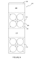
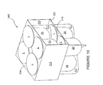
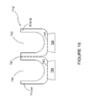
- FIGs 9 and 10 there is shown a blank 310 for forming a package 340.
- the blank 310 comprises a series of panels hinged one to the next in a linear series and includes a top panel 314 hinged to a first side panel 312 on a first side edge and to a second side panel 316 on a second side edge.
- First side panel 312 is hinged to a glue flap 320.
- Second side panel 316 is hinged to base panel 318.
- the blank 310 comprises a plurality of apertures 360; the top panel 314 comprises four apertures arranged in a two by two array.
- Each aperture 360 is shaped complementary to the shape of the container 24 and each aperture 360 comprises a pair of slots 361 disposed opposite one another for receiving the first flange F1 of the container 24.
- the slots 361 provide a location device for each container 24 and determine the orientation of each of the containers 24 with respect to one another and/or the package 340.
- the slots 361 of the aperture 360 are arranged so as to be perpendicular to the slots 361 of the adjacent apertures 360 and co-linear with the diagonally opposite aperture 360.
- the slots 361 of the diagonally opposite apertures 360 lie upon notional diagonal lines extending between corners of the top panel 314.
- the base panel 318 comprises four apertures 360 which are arranged identically to those in the top panel 314.
- the first flanges F1 of the containers 24 are arranged so as to form a stable base upon which the package 340 may rest. It will be appreciated that the first flanges F1 could be arranged in alternated configurations which would form a stable base.
- the second flange F2 and lids L of each of the containers 24 at least partially overlap with second flange F2 or lid L of the adjacent containers 24.
- the apertures 360 may be spaced and arranged so that the containers 24 do not overlap with one another.
- the package 340 is formed by grouping together four containers 24, filling with a product, applying a lid L, and placing the base panel 318 beneath each of the containers 24 such that the apertures 360 are in registry with the containers 24.
- the containers 24 are inserted into the apertures 360.
- the second side panel 316 is folded perpendicular to the base panel 318.
- the top panel 314 is then folded perpendicular to the second side panel 316 so as to be above the base panel 318.
- the first side panel 312 is then folded perpendicular to the top and base panels 314, 318.
- Glue flap 320 is then secured to a lowermost surface of the base panel 318.
- a second group of four containers 24 arranged in a two by two array is inserted into the apertures 360 of the top panel 314 to form a second or upper tier.
- the containers 24 may be filled with a product prior to placement in the carton or whilst within the carton during assembly.
- Figure 12 illustrates a package 440 formed from the container 24 of Figure 1E and the blank 410 of Figure 11 .
- the container 24 has been filled with a product and a lid L has been applied, preferably by gluing to optional second flange F2.
- the blank 410 has been constructed to form a base for holding the container 24 in an upright position.
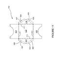
- Blank 410 comprises a base panel 412.
- the blank 410 also comprises first side panel 414, second side panel 416, first end panel 420 and second end panel 418 each of which is hinged to the base panel 412 along respective fold lines 411, 413, 417, 415.
- First and second end panels 418, 420 are substantially triangular in shape. End panels 418, 420 each comprise a pair of glue flaps 426, 428, 422, 424 respectively.
- Glue flaps 426, 428, 422, 428 are hinged to the respective end panels 418, 420 by a respective fold line 427, 429, 423, 425.
- Side panels 414, 416 each comprise an arcuate recess struck from an edge of the side panel opposing the hinged connection to the base 412.
- the recess is shaped to be complimentary to the shape of the container 24.
- the blank 410 is constructed to form a foot or stabiliser by folding the end panels 418, 420 to be substantially perpendicular to base panel 412.
- the glue flaps 426, 428, 422, 424 are folded to be substantially perpendicular to the respective end panel 418, 420.
- Adhesive is applied to either the glue flaps 426, 428, 422, 424 or to a corresponding region of the side panels 414, 416.
- the side panels 414, 416 are arranged so that a slot or gap extends between the end panels 418, 420.
- This slot can receive the first flange F1 of the container 24; the recesses form an aperture which can receive a portion of the side, end or base walls of the container 24.
- the package 524 comprises a foot or stabiliser 530 in order to allow the package 524 to stand in an upright position.
- the package 524 also comprises a lid L which has been affixed to the optional second flange F2.
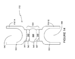
- the package 524 is constructed using the blank 512 illustrated in Figure 14 .
- the blank 512 comprises a pair of flange panels F501A, F501B, which are connected together by stabiliser panels 542, 544, 546, which are hingedly connected in a linear series between the flange panels F501A, F501B.
- First stabiliser panel 542 is coupled to flange panel F501A by fold line 541 and to second stabiliser panel 544 by fold line 543.
- Second stabiliser panel 544 is coupled to third stabiliser panel 546 by fold line 545.
- Third stabiliser panel 546 is coupled to second flange panel F501B by fold line 547.
- the flange panels F501A, F501B each comprise a recess 540, 548 shaped to accommodate the side, end or base walls of the container 24.
- the foot or stabiliser is formed by folding the first main panel 551 and first stabiliser panel 542 about fold line 543 so as to overlay the second and third stabiliser panels 544, 546 and second main panel 553; first main panel 551 is then folded back about fold line 541 to overlay first stabiliser panel 542.
- the second flange panel F501B and third stabiliser panel 546 are folded about fold line 545, the second flange panel F501A is then folded back about fold line 547 to overlay the third stabiliser panel 546.
- Adhesive is then applied to the first flange panel F501A and the second flange panel F501B, or to opposing sides of the first flange F1 of the container 24.
- the flange panels F501A, F501B are then secured to the opposing sides the first flange F1 of the container 24.
- FIG. 13B and Figure 15 illustrate a package 624 according to a sixth embodiment of the present invention, in which the package 624 comprises a foot or stabiliser 630 in order to allow the package 624 to stand in an upright position.
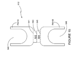
- the package 624 is formed from the blank 612 of Figure 7 ; the blank 612 comprises a pair of flange panels F601A, F601B interconnected by a pair of strut panels 642, 644.
- the flange panels F601A, F601B are shaped to accommodate the side, end or base walls of the container 24.
- Adhesive is applied to the first flange panel F601A and the second flange panel F601B. Adhesive is not applied to a lowermost portion, adjacent the strut panels 642, 644 of each of the flange panels F601A, F601B, such that these portions may be folded outwardly away from one another to form an inverted V shape.
- the folded portions of the flange panels F601A, F601B form legs upon which the package 624 can rest in an upright position.
- the lowermost portions of each of the flange panels F601A, F601B may comprise one or more fold lines, not shown, which define in part the legs, and facilitate folding the lowermost portions outwardly.
- the strut panels 642, 644 may be folded about fold line 643 to be placed in overlapping relation with one another, and about fold lines 641, 645 to be placed in overlapping relationship with, and disposed between, the lowermost portions of each of the flange panels F601A, F601B when the legs are not in use.
- Figure 16 illustrates a blank 712 for forming a package according to a seventh embodiment of the present invention
- the blank 712 comprises a pair of flange panels F701A, F701B.
- the flange panels F701A, 701B are hingedly connected together by fold line 741 which extends alone a side edge thereof.
- a foot panel 744, 746 is attached to each of the flange panels F701A, F701B along an end edge by a respective fold line 743, 745.
- the flange panels F701A, F701B are secured to the container 24 by adhering the flange panels F701A, F701B to opposing sides of the first flange F1; no adhesive is applied to the foot panels 744, 746.
- the package can be filled with a product and if desired a lid L can be applied preferably by securing to the second flange F2.
- the foot panels 744, 746 can be folded to be perpendicular to the first flange F1 so as to be coplanar with one another. In this way the foot panels 744, 746 provide a stable base for the package, which can be deployed when desired.
- any reference to hinged connection should not be construed as necessarily referring to a single fold line only; indeed it is envisaged that hinged connection can be formed from one or more of the following, a short slit, a frangible line or a fold line without departing from the scope of the invention.
Landscapes
- Engineering & Computer Science (AREA)
- Mechanical Engineering (AREA)
- Ceramic Engineering (AREA)
- Packages (AREA)
Abstract
A package comprising at least one article which includes a flange extending outwardly from a base thereof. The package includes a carton having at least one panel forming a foot or stabiliser. The carton includes a connector for connecting the carton with the foot or stabiliser via the flange of the at least one article.
Description
- The present invention relates to a package for holding one or more articles more specifically, but not exclusively, to packaging articles having a vertical flange.
- In the field of packaging it is often required to provide consumers with a package comprising multiple primary product containers. Such multi-packs are desirable for shipping and distribution and for display of promotional information. For cost and environmental considerations, such cartons or carriers need to be formed from as little material as possible, and cause as little wastage in the materials from which they are formed as possible. Another consideration is the strength of the packaging and its suitability for holding and transporting large weights of articles.
- Co-pending European Patent Application
EP12160673.5 GB 1104828.7 - It is desirable therefore to provide a package which can accommodate such articles.
- The present invention seeks to overcome or at least mitigate the problems of the prior art.
- According to a first aspect of the present invention there is provided a package comprising at least one article, which comprises a flange extending outwardly from a base thereof, wherein the package further comprises a carton that includes one or more panels forming a foot or stabiliser for the at least one article and a connector for connecting the foot or stabiliser with the at least one article via the flange of the at least one article.
- According to a second aspect of the present invention there is provided a package comprising a carton and two or more articles, each of the two or more articles comprising a flange extending outwardly from a base thereof wherein the carton comprises two or more apertures, each of which receives a respective one of said two or more articles, wherein the carton further comprises a locating device which receives the flange of the each article so that each article takes a predetermined orientation with respect to the other articles, and wherein the two or more articles are arranged such that the flange of the two or more articles together form a stable base of the package.
- Preferably, the at least one article or the each article defines a tubular axis, the flange of the at least one article or the each article extends from at least a base wall of the at least one article or the each article along the tubular axis.
- Alternatively, the locating device comprises a slot formed in a panel of the carton.
- Preferably, there comprises at least one weakened line of severance.
- Alternatively, the foot or stabiliser may be deployed in a first position and stowed in a second position.
- According to a third aspect of the present invention there is provided a package comprising at least one article which comprises a flange extending outwardly therefrom, and a carton having a slot for receiving the flange of the at least one article, the slot being defined in or between one or more panels of the carton.
- According to a fourth aspect of the present invention there is provided a package comprising at least one article, which comprises a flange extending outwardly therefrom, and a carton having at least one wall panel, wherein the at least one wall panel comprises a recess shaped to accommodate at least a portion of the at least one article, and wherein said at least one wall panel is secured to the flange of the at least one article, the carton comprising at least one foot panel coupled to the at least one wall panel.
- According to a fifth aspect of the present invention there is provided a package comprising a plurality of articles, each of which articles comprises a flange standing outwardly from a base thereof, each of the flanges being coupled to one or more foot panels which can be folded into overlapping relationship with the each flange, the each flange and the foot panels being received in a respective slot defined in one or more panels of a carton.
- Exemplary embodiments of the invention will now be described with reference to the accompanying drawings, in which:
- FIGURE 1A
- is a perspective view from above of an exemplary part-formed container for forming a package of the present invention;
- FIGURE 1B
- is a side view of an exemplary container for forming a package of the present invention;
- FIGURE 1C
- is an end view of the container of
Figure 1B ; - FIGURE 1D
- is a top view of the container of
Figure 1B ; - FIGURE 1E
- is a perspective view of the container of
Figure 1B ; - FIGURE 2
- is a plan view from above of a blank for forming a package according to a first embodiment;
- FIGURE 3
- is a perspective view from above of a stage of assembly of a package according to the first embodiment;
- FIGURE 4
- is a perspective view from above of a second stage of assembly of a package according to the first embodiment;
- FIGURE 5
- is a perspective view from above of a package according to the first embodiment;
- FIGURE 6
- is a perspective view from above of the deployment of a container from the package of the first embodiment;
- FIGURE 7
- is a plan view from above of a blank for forming a package according to a second embodiment;
- FIGURE 8
- is a perspective view from above of a package according to a second embodiment;
- FIGURE 9
- is a perspective view from above of a blank for forming a package according to a third embodiment;
- FIGURE 10
- is a perspective view from above of a package formed for the blank of
Figure 9 ; - FIGURE 11
- illustrates a plan view of a blank for forming a package according to a fourth embodiment;
- FIGURE 12
- illustrates a perspective view of a package according to the fourth embodiment;
- FIGURE 13A
- illustrates a perspective view of the package according to a fifth embodiment;
- FIGURE 13B
- illustrates a perspective view of a package according to a sixth embodiment;
- FIGURE 14
- illustrates a blank for forming the package of
Figure 13A ; - FIGURE 15
- illustrates a blank for forming the package of
Figure 13B ; and - FIGURE 16
- illustrates a blank for forming a package according to a seventh embodiment.
- Detailed descriptions of specific embodiments of the packages, blanks and cartons are disclosed herein. It will be understood that the disclosed embodiments are merely examples of the way in which certain aspects of the invention can be implemented and do not represent an exhaustive list of all of the ways the invention may be embodied. Indeed, it will be understood that the packages, blanks and cartons described herein may be embodied in various and alternative forms. The Figures are not necessarily to scale and some features may be exaggerated or minimised to show details of particular components. Well-known components, materials or methods are not necessarily described in great detail in order to avoid obscuring the present disclosure. Any specific structural and functional details disclosed herein are not to be interpreted as limiting, but merely as a basis for the claims and as a representative basis for teaching one skilled in the art to variously employ the invention.
-
Figures 1A to 1E illustrate aprimary container 24. Optionally theprimary container 24 is formed by thermoforming a sheet of material, preferably paperboard; theprimary container 24 is formed in two or more sections P1, P2, preferably two sections P1, P2. Each section P1, P2 comprises a first flange F1. The first flange F1 is provided for securing the sections P1, P2 of thecontainer 24 together. - The method of forming the primary package or
container 24 and theprimary package 24 itself are the subject of co-pending European patent application numberEP12160673.5 container 24, and the method of forming of the package in two or more sections. - Optionally, each section P1, P2 of the
container 24 comprises a part of a second flange F2. The second flange F2 facilitates securing a lid or cover L best shown inFigure 4 to theprimary package 24. - It is envisaged that in alternative embodiments the present invention may be utilised with
primary containers 24 which are formed as a unitary piece, which unitary piece is formed with a flange. - The
primary container 24 comprisesside walls base wall 20;base wall 20 is optionally dome shaped. - Preferably, the two sections P1, P2 of the
container 24 are hinged together by ahinge connection 19. - The
container 24 comprises an open end through which a product such as foodstuffs or beverages are loaded. - Turning now to
Figures 2 to 5 there is shown acarton 140 and blank 110 for forming thecarton 140, whichcarton 140 forms a package P according to a first embodiment of the present invention. The blank 110 comprises panels for forming atop panel 112,first side panel 114,base panel 116 andsecond side panel 118 and aglue flap 120. - In the illustrated embodiment in
Figures 2 to 4 the blank 110 is shaped and arranged to accommodate fourcontainers 24 arranged in a two by two array; in alternative embodiments the blank 110 may be arranged to accommodate a different number of containers or articles and/or a different array configuration. - The
top panel 112 comprises foursections respective container 24. Thefirst section 112A is severable from each of second andthird sections severance Second section 112B is severable from each of first and afourth section severance Third section 112C is severable fromfourth section 112D by weakened line ofseverance 117B.Top panel 112 is hinged tofirst side panel 114.First side panel 114 comprises afirst part 114A and asecond part 114B which are separated from one another. In alternative embodiments,first part 114A andsecond part 114B may be coupled to one another by a weakened line of severance. - The
first part 114A is hinged to thetop panel 112 by afold line 115A, which extends at least partially along a side edge ofthird section 112C. - The
second part 114B is hinged to thetop panel 112 by afold line 115B which extends at least partially along a side edge offourth section 112D. In alternative embodiments foldlines - The
first side wall 114 is hinged to thebase panel 116. - The
base panel 116 comprises afirst component 116A and asecond component 116B. The first andsecond components - Each of the first and
second components containers 24. The first andsecond components second part 116B. -
Second part 116B comprises a series ofpanels first panel 124 is hingedly connected tosecond panel 126 alongfold line 127; the second panel is hingedly connected to thethird panel 128 alongfold line 129 and the third panel is hingedly connected to fourth panel alongfold line 131. - The second and
third panels first side wall 114, in particular tosecond part 114B viariser panel 122.Second panel 126 is coupled toriser panel 122 viafold line 123B.Third panel 128 is coupled toriser panel 122 viafold line 123A.Riser panel 122 is coupled tosecond part 114B viafold line 121. Foldlines fold line 121 and are disposed at opposed ends offold line 121. - Fold
lines fold line 129. Anarcuate cutline 125 or weakened line of severance is interposed betweenfold lines fold lines line 125 together form a V shape which converges atfold line 129. Asecond riser panel 132 is disposed at the opposite end of second andthird panels - A weakened line of
severance 135 bisects each of the first, second, third and fourth panels, 124, 126, 128, 130. A first slot S1 is disposed betweenriser panel 122 and weakenedline 135. A second slot S2 is disposed betweenriser panel 132 and weakenedline 135. Third and fourth slots S3, S4 are similarly formed insecond component 116B. - Each of slots S1 and S2 extends across the second and
third panels Base panel 116 is coupled tosecond side panel 118.Second side panel 118 comprises afirst element 118A and asecond element 118B coupled to respective ones of the first andsecond components base panel 116, byfold line 133. - First and
second elements -
Second side panel 118 is coupled toglue panel 120.Glue panel 120 comprisesglue flap 120A andglue flap 120B which are separate from one another.Glue flap 120A is coupled tofirst element 118A byfold line 111A andglue flap 120B is coupled tosecond element 118B byfold line 111B. - Turning to the construction of the carton as illustrated in
Figures 3 ,4 and5 it is envisaged that the carton can be formed by a series of sequential folding operations in a straight line machine so that the carton is not required to be rotated or inverted to complete its construction. The folding process is not limited to that described below and may be altered according to particular manufacturing requirements. - The
base panels third panels Riser panels third panels fourth panels carton 140 may rest, and form part of abase structure 180 together with second andthird panels containers 24. - A group of
containers 24 are received on each of the first andsecond components container 24 which first flange F1 extends downward of the base of thecontainers 24. - The first and
second side panels containers 24. - The
top panel 112 is folded to overlay the group ofcontainers 24. Thecontainers 24 may be filled with a product prior to placement on thebase panel 116 or prior to folding thetop panel 112 about thecontainers 24. Lids L are applied to thecontainer 24. - Adhesive may be applied either to the second flanges F2 or to the lid L prior to sealing of the open ends of the
containers 24. Optionally, thetop panel 112 can be secured to the lids L of thecontainers 24. - In alternative embodiments the
top panel 112 may form the lid of each of thecontainers 24. - The
glue panel 120 may then be folded about thetop panel 112 to secure the panels in a tubular structure about thecontainers 24. In some embodiments theglue panel 120 may be folded about thecontainers 24 before folding thetop panel 112. -
Figure 4 illustrates the assembled package P holding each of thecontainers 24. Thecontainers 24 may be separated from the package P by severing therespective severance lines Figure 6 , where anindividual container 24 has been separated from the remainingcontainers 24. - Referring now to
Figures 7 to 16 , there are shown alternative embodiments of the present invention. In the second and third illustrated embodiments, like numerals have, where possible, been used to denote like parts, albeit with the addition of the prefix "200" or "300" and so on to indicate that these features belong to the second embodiment. The alternative embodiments share many common features with the first embodiment and therefore only the differences from the embodiment illustrated inFigures 1 to 6 will be described in any greater detail. -
Figure 7 illustrates a blank 210 for forming thepackage 240 illustrated inFigure 8 . -
Blank 210 comprises atop panel 212 first hinged tofirst side panel 214 alongfold line 215 and tosecond side panel 218 alongfold line 213.First side panel 214 is hinged tofirst base panel 216A alongfold line 217.Second side panel 218 is hinged tosecond base panel 216B alongfold line 211.First side panel 214 comprises four slots S1, S2, S3, S4 extending between thetop panel 212 and thefirst base panel 216A.Second side panel 218 comprises four slots S1, S2, S3, S4 extending betweentop panels 212 andsecond base panel 216B. Slots S1, S2, S3, S4 insecond side panel 218 are co-linear with slots S1, S2, S3, S4 infirst side panel 214. -
Blank 210 comprises a first weakened line ofseverance 250 extending across thefirst base panel 216A,first side panel 214,top panel 212,second side panel 218 andsecond side panel 216B. First line ofseverance 250 is disposed between first slot S1 and second slot S2. - A second line of
severance 252 extends across blank 210 from a free edge offirst base panel 216A to a free edge ofsecond base panel 216B; second line ofseverance 252 is disposed between slots S2 and slots S3. - A third weakened line of
severance 254 extends across the blank 210 and is disposed between slots S3 and S4. - First, second and third weakened lines of
severance Figure 8 . - The package of
Figure 8 is constructed by wrapping the blank 210 ofFigure 7 about a group ofcontainers 24. In the illustrated embodiment thepackage 240 accommodates fourcontainers 24 arranged in a four by one array.Top panel 212 provides a lid for open ends of each of thecontainers 24. The slots S1, S2, S3, S4 receive at least a portion of a first flange F1 of a respective one of thecontainers 24. - First and
second base panels - Each of the
containers 24 may be separated from thepackage 240 by securing the respective one of the first, second and third weakened lines ofseverance Figures 9 and10 , there is shown a blank 310 for forming apackage 340. The blank 310 comprises a series of panels hinged one to the next in a linear series and includes atop panel 314 hinged to afirst side panel 312 on a first side edge and to asecond side panel 316 on a second side edge.First side panel 312 is hinged to aglue flap 320.Second side panel 316 is hinged tobase panel 318. - The blank 310 comprises a plurality of
apertures 360; thetop panel 314 comprises four apertures arranged in a two by two array. Eachaperture 360 is shaped complementary to the shape of thecontainer 24 and eachaperture 360 comprises a pair ofslots 361 disposed opposite one another for receiving the first flange F1 of thecontainer 24. - The
slots 361 provide a location device for eachcontainer 24 and determine the orientation of each of thecontainers 24 with respect to one another and/or thepackage 340. - In the illustrated embodiment the
slots 361 of theaperture 360 are arranged so as to be perpendicular to theslots 361 of theadjacent apertures 360 and co-linear with the diagonallyopposite aperture 360. Preferably, theslots 361 of the diagonallyopposite apertures 360 lie upon notional diagonal lines extending between corners of thetop panel 314. - The
base panel 318 comprises fourapertures 360 which are arranged identically to those in thetop panel 314. When thepackage 340 is assembled the first flanges F1 of thecontainers 24 are arranged so as to form a stable base upon which thepackage 340 may rest. It will be appreciated that the first flanges F1 could be arranged in alternated configurations which would form a stable base. - In the illustrated embodiment the second flange F2 and lids L of each of the
containers 24 at least partially overlap with second flange F2 or lid L of theadjacent containers 24. In alternative embodiments theapertures 360 may be spaced and arranged so that thecontainers 24 do not overlap with one another. - The
package 340 is formed by grouping together fourcontainers 24, filling with a product, applying a lid L, and placing thebase panel 318 beneath each of thecontainers 24 such that theapertures 360 are in registry with thecontainers 24. Thecontainers 24 are inserted into theapertures 360. - The
second side panel 316 is folded perpendicular to thebase panel 318. Thetop panel 314 is then folded perpendicular to thesecond side panel 316 so as to be above thebase panel 318. Thefirst side panel 312 is then folded perpendicular to the top andbase panels Glue flap 320 is then secured to a lowermost surface of thebase panel 318. - A second group of four
containers 24 arranged in a two by two array is inserted into theapertures 360 of thetop panel 314 to form a second or upper tier. Thecontainers 24 may be filled with a product prior to placement in the carton or whilst within the carton during assembly. -
Figure 12 illustrates apackage 440 formed from thecontainer 24 ofFigure 1E and the blank 410 ofFigure 11 . - The
container 24 has been filled with a product and a lid L has been applied, preferably by gluing to optional second flange F2. - The blank 410 has been constructed to form a base for holding the
container 24 in an upright position. -
Blank 410 comprises abase panel 412. The blank 410 also comprisesfirst side panel 414,second side panel 416,first end panel 420 andsecond end panel 418 each of which is hinged to thebase panel 412 alongrespective fold lines - First and
second end panels End panels - Glue flaps 426, 428, 422, 428 are hinged to the
respective end panels respective fold line -
Side panels base 412. The recess is shaped to be complimentary to the shape of thecontainer 24. - The blank 410 is constructed to form a foot or stabiliser by folding the
end panels base panel 412. The glue flaps 426, 428, 422, 424 are folded to be substantially perpendicular to therespective end panel side panels -
Side panels - The
side panels end panels container 24; the recesses form an aperture which can receive a portion of the side, end or base walls of thecontainer 24. - Turning now to
Figures 13A and14 , there is illustrated a fifth embodiment of the present invention in which thepackage 524 comprises a foot orstabiliser 530 in order to allow thepackage 524 to stand in an upright position. Thepackage 524 also comprises a lid L which has been affixed to the optional second flange F2. Thepackage 524 is constructed using the blank 512 illustrated inFigure 14 . The blank 512 comprises a pair of flange panels F501A, F501B, which are connected together bystabiliser panels First stabiliser panel 542 is coupled to flange panel F501A byfold line 541 and tosecond stabiliser panel 544 byfold line 543.Second stabiliser panel 544 is coupled tothird stabiliser panel 546 byfold line 545.Third stabiliser panel 546 is coupled to second flange panel F501B byfold line 547. - The flange panels F501A, F501B each comprise a
recess container 24. The foot or stabiliser is formed by folding the firstmain panel 551 andfirst stabiliser panel 542 aboutfold line 543 so as to overlay the second andthird stabiliser panels main panel 553; firstmain panel 551 is then folded back aboutfold line 541 to overlayfirst stabiliser panel 542. The second flange panel F501B andthird stabiliser panel 546 are folded aboutfold line 545, the second flange panel F501A is then folded back aboutfold line 547 to overlay thethird stabiliser panel 546. Adhesive is then applied to the first flange panel F501A and the second flange panel F501B, or to opposing sides of the first flange F1 of thecontainer 24. - The flange panels F501A, F501B are then secured to the opposing sides the first flange F1 of the
container 24. -
Figure 13B andFigure 15 illustrate apackage 624 according to a sixth embodiment of the present invention, in which thepackage 624 comprises a foot orstabiliser 630 in order to allow thepackage 624 to stand in an upright position. Thepackage 624 is formed from the blank 612 ofFigure 7 ; the blank 612 comprises a pair of flange panels F601A, F601B interconnected by a pair ofstrut panels container 24. - Adhesive is applied to the first flange panel F601A and the second flange panel F601B. Adhesive is not applied to a lowermost portion, adjacent the
strut panels package 624 can rest in an upright position. The lowermost portions of each of the flange panels F601A, F601B may comprise one or more fold lines, not shown, which define in part the legs, and facilitate folding the lowermost portions outwardly. - The
strut panels fold line 643 to be placed in overlapping relation with one another, and aboutfold lines -
Figure 16 illustrates a blank 712 for forming a package according to a seventh embodiment of the present invention; the blank 712 comprises a pair of flange panels F701A, F701B. The flange panels F701A, 701B are hingedly connected together byfold line 741 which extends alone a side edge thereof. - A
foot panel respective fold line - The flange panels F701A, F701B are secured to the
container 24 by adhering the flange panels F701A, F701B to opposing sides of the first flange F1; no adhesive is applied to thefoot panels - The package can be filled with a product and if desired a lid L can be applied preferably by securing to the second flange F2.
- When it is desired, for example when an end user wishes to consume the product, the
foot panels foot panels - It can be appreciated that various changes may be made within the scope of the present invention, for example, the size and shape of the panels and apertures may be adjusted to accommodate articles of differing size or shape. It will be recognised that as used herein, directional references such as "top", "bottom", "front", "back", "end", "side", "inner", "outer", "upper" and "lower" do not limit the respective panels to such orientation, but merely serve to distinguish these panels from one another. Any reference to hinged connection should not be construed as necessarily referring to a single fold line only; indeed it is envisaged that hinged connection can be formed from one or more of the following, a short slit, a frangible line or a fold line without departing from the scope of the invention.
Claims (9)
- A package comprising at least one article which comprises a flange extending outwardly from a base thereof, wherein the package further comprises a carton that includes one or more panels forming a foot or stabiliser for the at least one article and a connector for connecting the foot or stabiliser with the at least one article via the flange of the at least one article.
- A package comprising a carton and two or more articles, each of the two or more articles comprising a flange extending outwardly from a base thereof wherein the carton comprises two or more apertures each of which receives a respective one of said two or more articles, wherein the carton further comprises a locating device which receives the flange of each article so that each article takes a predetermined orientation with respect to the other article(s) and wherein the two or more articles are arranged such that the flanges of the two or more articles together form a stable base of the package.
- A package according to claim 1 or claim 2 wherein the at least one article or the each article defines a tubular axis, the flange of the at least one article or the each article extends from at least a base wall of the at least one article or the each article along the tubular axis.
- A package according to claim 2 wherein the locating device comprises a slot formed in a panel of the carton.
- A package according to any of claims 1 to 4 wherein the carton comprises at least one weakened line of severance.
- A package according to claim 1 wherein the foot or stabiliser may be deployed in a first position and stowed in a second position.
- A package comprising at least one article which comprises: a flange extending outwardly therefrom; and a carton having a slot for receiving the flange of the at least one article, the slot being defined in or between one or more panels of the carton.
- A package comprising: at least one article which comprises a flange extending outwardly therefrom; and a carton having at least one wall panel, wherein the at least one wall panel comprises a recess shaped to accommodate at least a portion of the at least one article, and wherein said at least one wall panel is secured to the flange of the at least one article, the carton comprising at least one foot panel coupled to the at least one wall panel.
- A package comprising a plurality of articles each of which articles comprises a flange standing outwardly from a base thereof, each of the flanges being coupled to one or more foot panels which can be folded into overlapping relationship with the each flange, the each flange and the foot panels being received in a respective slot defined in one or more panels of a carton.
Applications Claiming Priority (2)
| Application Number | Priority Date | Filing Date | Title |
|---|---|---|---|
| GBGB1104828.7A GB201104828D0 (en) | 2011-03-22 | 2011-03-22 | Package and method of forming the same |
| GBGB1104826.1A GB201104826D0 (en) | 2011-03-22 | 2011-03-22 | Carton and blank for forming a package |
Publications (1)
| Publication Number | Publication Date |
|---|---|
| EP2502836A1 true EP2502836A1 (en) | 2012-09-26 |
Family
ID=45936875
Family Applications (1)
| Application Number | Title | Priority Date | Filing Date |
|---|---|---|---|
| EP12160685A Withdrawn EP2502836A1 (en) | 2011-03-22 | 2012-03-22 | Carton and blank for forming a package |
Country Status (1)
| Country | Link |
|---|---|
| EP (1) | EP2502836A1 (en) |
Citations (5)
| Publication number | Priority date | Publication date | Assignee | Title |
|---|---|---|---|---|
| US3454157A (en) * | 1967-09-08 | 1969-07-08 | Federal Paper Board Co Inc | Paperboard blank for carded items and combination of carded items and paperboard container |
| US3527016A (en) * | 1967-09-06 | 1970-09-08 | Responsabilite Ltd Cartonnages | Apparatus for packaging a plurality of cylindrical articles |
| FR2251199A5 (en) * | 1973-11-13 | 1975-06-06 | Journee Paul | |
| GB1467423A (en) * | 1974-05-09 | 1977-03-16 | Drg Packaging Ltd | Packaging tubular articles |
| FR2471924A1 (en) * | 1979-12-20 | 1981-06-26 | Soulie Et Fils G | Packing containers with common lid - have lid sealed with front and back flap with perforated edges to open either box |
-
2012
- 2012-03-22 EP EP12160685A patent/EP2502836A1/en not_active Withdrawn
Patent Citations (5)
| Publication number | Priority date | Publication date | Assignee | Title |
|---|---|---|---|---|
| US3527016A (en) * | 1967-09-06 | 1970-09-08 | Responsabilite Ltd Cartonnages | Apparatus for packaging a plurality of cylindrical articles |
| US3454157A (en) * | 1967-09-08 | 1969-07-08 | Federal Paper Board Co Inc | Paperboard blank for carded items and combination of carded items and paperboard container |
| FR2251199A5 (en) * | 1973-11-13 | 1975-06-06 | Journee Paul | |
| GB1467423A (en) * | 1974-05-09 | 1977-03-16 | Drg Packaging Ltd | Packaging tubular articles |
| FR2471924A1 (en) * | 1979-12-20 | 1981-06-26 | Soulie Et Fils G | Packing containers with common lid - have lid sealed with front and back flap with perforated edges to open either box |
Similar Documents
| Publication | Publication Date | Title |
|---|---|---|
| US10569947B2 (en) | Carton and carton blank and a handle structure therefor | |
| US10301091B2 (en) | Carton and blank therefor | |
| US20230159243A1 (en) | Basket style carrier and blank therefor | |
| US20110253587A1 (en) | Carton tray | |
| US10173804B2 (en) | Carrier and blank therefor | |
| EP3337729B1 (en) | Reinforced package, carton, combination of a carton blank and a bag, and method of forming a reinforced package | |
| JP2009525234A (en) | Package for container | |
| US20240002122A1 (en) | Carton and blank therefor | |
| US9604768B2 (en) | Carton and carton blank | |
| AU2013266528B2 (en) | Carton and carton blank | |
| US10040596B2 (en) | Carton and carton blank | |
| US11312552B2 (en) | Article carrier and blank therefor | |
| EP3222552B1 (en) | Carton and blank therefor | |
| US20180134443A1 (en) | Reinforced handle structure and carton | |
| US11891226B2 (en) | Basket style carrier, shipping carton and package system | |
| US20170313469A1 (en) | Carton and blank therefor | |
| US10279951B2 (en) | Carton and carton blank | |
| CN114728724A (en) | Article carrier, blank and method of constructing an article carrier | |
| US20170217630A1 (en) | Carton and carton blank | |
| JP5712307B2 (en) | Carton and carton blank | |
| US20140373486A1 (en) | Carton, carton blank and method of forming a loaded carton | |
| EP2502839A1 (en) | Primary and secondary package combination, the secondary package and blank for forming the secondary package | |
| WO2017091457A1 (en) | Article carrier and blank therefor | |
| JP6452962B2 (en) | Carton and carton blank | |
| WO2017062267A1 (en) | Article carrier and blank therefor |
Legal Events
| Date | Code | Title | Description |
|---|---|---|---|
| PUAI | Public reference made under article 153(3) epc to a published international application that has entered the european phase |
Free format text: ORIGINAL CODE: 0009012 |
|
| 17P | Request for examination filed |
Effective date: 20120322 |
|
| AK | Designated contracting states |
Kind code of ref document: A1 Designated state(s): AL AT BE BG CH CY CZ DE DK EE ES FI FR GB GR HR HU IE IS IT LI LT LU LV MC MK MT NL NO PL PT RO RS SE SI SK SM TR |
|
| AX | Request for extension of the european patent |
Extension state: BA ME |
|
| STAA | Information on the status of an ep patent application or granted ep patent |
Free format text: STATUS: THE APPLICATION IS DEEMED TO BE WITHDRAWN |
|
| 18D | Application deemed to be withdrawn |
Effective date: 20130327 |