EP2502793A1 - Inflatable airbag - Google Patents
Inflatable airbag Download PDFInfo
- Publication number
- EP2502793A1 EP2502793A1 EP11159336A EP11159336A EP2502793A1 EP 2502793 A1 EP2502793 A1 EP 2502793A1 EP 11159336 A EP11159336 A EP 11159336A EP 11159336 A EP11159336 A EP 11159336A EP 2502793 A1 EP2502793 A1 EP 2502793A1
- Authority
- EP
- European Patent Office
- Prior art keywords
- airbag
- inflatable
- seam
- longitudinal
- internal
- Prior art date
- Legal status (The legal status is an assumption and is not a legal conclusion. Google has not performed a legal analysis and makes no representation as to the accuracy of the status listed.)
- Granted
Links
Images


Classifications
-
- B—PERFORMING OPERATIONS; TRANSPORTING
- B60—VEHICLES IN GENERAL
- B60R—VEHICLES, VEHICLE FITTINGS, OR VEHICLE PARTS, NOT OTHERWISE PROVIDED FOR
- B60R21/00—Arrangements or fittings on vehicles for protecting or preventing injuries to occupants or pedestrians in case of accidents or other traffic risks
- B60R21/02—Occupant safety arrangements or fittings, e.g. crash pads
- B60R21/16—Inflatable occupant restraints or confinements designed to inflate upon impact or impending impact, e.g. air bags
- B60R21/23—Inflatable members
- B60R21/231—Inflatable members characterised by their shape, construction or spatial configuration
- B60R21/232—Curtain-type airbags deploying mainly in a vertical direction from their top edge
-
- B—PERFORMING OPERATIONS; TRANSPORTING
- B60—VEHICLES IN GENERAL
- B60R—VEHICLES, VEHICLE FITTINGS, OR VEHICLE PARTS, NOT OTHERWISE PROVIDED FOR
- B60R21/00—Arrangements or fittings on vehicles for protecting or preventing injuries to occupants or pedestrians in case of accidents or other traffic risks
- B60R21/02—Occupant safety arrangements or fittings, e.g. crash pads
- B60R21/16—Inflatable occupant restraints or confinements designed to inflate upon impact or impending impact, e.g. air bags
- B60R21/20—Arrangements for storing inflatable members in their non-use or deflated condition; Arrangement or mounting of air bag modules or components
- B60R21/213—Arrangements for storing inflatable members in their non-use or deflated condition; Arrangement or mounting of air bag modules or components in vehicle roof frames or pillars
Definitions
- the present disclosure relates to an inflatable airbag according to the preamble of claim 1.
- the airbag is adapted to deploy in a curtain-like shape over a side surface of a vehicle interior for protecting a vehicle occupant.
- the disclosure further relates to a vehicle comprising such an inflatable airbag and the use of a second internal seam.
- Document US 7,740,270 B2 discloses a curtain air bag comprising a main inflation chamber and a sub-inflation chamber which are defined by a partition portion formed by seams inside surfaces of the air bag body, and a gas flow regulation passage formed as a partly non-bonding portion of the partition portion.
- the main and sub-inflation chambers are respectively located at an upper side and a lower side of the air bag body and communicate with each other through the gas flow regulation passage.
- the curtain airbag is stored in/at the cant rail of the vehicle roof in a rolled state and is deployed when needed.
- the cant rail frequently has a curved shape.
- most curtain airbags have a straight upper longitudinal edge. Therefore, the airbag may adapt to the shape of the curved cant rail when the airbag is inflated. This will cause the airbag to slightly bend. There is further a risk that one or more wrinkles are created in the airbag, primarily at the lower longitudinal side of the airbag. Both of these phenomena may affect the airbag in such a way that its longitudinal extension is reduced. Thereby the airbag may be pulled away from the intended coverage zones.
- the object of the present disclosure is to overcome or ameliorate at least one of the disadvantages of the prior art, or to provide a useful alternative.
- the airbag is not pulled away from the intended coverage zones upon deployment.
- the rear lower corner of the airbag upon deployment of the airbag actually covers what it is intended to cover in order to protect the head of a possible rear set occupant.
- an inflatable airbag adapted to deploy in a curtain-like shape over a side surface of a vehicle interior for protecting a vehicle occupant.
- the airbag has a longitudinal, a depth and a height direction.
- the airbag comprises a first longitudinal end portion, a second longitudinal end portion, and a central portion therebetween having a centre.
- the airbag further comprises a circumferential seam along substantially its entire circumference, the circumferential seam enclosing an at least partly inflatable portion of the airbag.
- the airbag further comprises at least a first internal seam, surrounded by the circumferential seam.
- the airbag comprises a second internal seam in at least one of the first or second longitudinal end portions.
- the second internal seam extends substantially in the longitudinal direction between a first end point adjacent to the circumferential seam and a second end point located longitudinally closer to the centre of the airbag than the first end point, the second internal seam together with a portion of the circumferential seam forming a longitudinally extending airbag cell.
- the second end point is spaced from any of the at least a first internal seam and the circumferential seam by a distance of at least 10 cm, preferably at least 15 cm and most preferably at least 20 cm, such that, when the airbag is deployed, the longitudinally extending airbag cell is pressurized at substantially the same rate as the rest of the inflatable portion of the airbag.
- seam is herein used to comprise not only conventional seams, but also welding, thermal bonding, adhesives, clamping or that the airbag has been woven as OWP, i.e. one-piece woven.
- cell denotes herein an airbag structure which has only one in-out passage, while the term channel is used for an airbag structure comprising at least two in-out passages, such that a gas stream may flow through the channel.
- the first longitudinal end portion may be located either at the front or the rear end of the airbag, where front and rear relate to the vehicle, in which the airbag is to be mounted.
- the second longitudinal end portion is the opposite end portion. Hence, if the first longitudinal end portion is at the front, the second longitudinal end portion is at the rear, and vice versa.
- the airbag When inflating the airbag according to the disclosure, the airbag will contract in the height direction as compared to in a flat state, i.e. unrolled but not inflated, since the airbag expands in the depth direction. Moreover, since the second internal seam is arranged in at least one of the longitudinal end portions, the airbag will in that longitudinal end portion contract more in the height direction as compared to a prior art airbag. Therefore, the airbag according to the disclosure may more easily adapt to the shape of a curved cant rail. In addition, the risk of creating a wrinkle is reduced due to the additional height direction contraction. The above-mentioned problem with longitudinal contraction is therefore at least partly counteracted. Hence the risk of pulling the airbag away from the intended coverage zones is reduced.
- the at least one longitudinally extending airbag cell located at the rear longitudinal end portion, it may be ensured that the rear lower corner of the airbag upon deployment of the airbag actually covers the intended coverage zone in order to protect the head of a possible rear set occupant.
- a longitudinally extending airbag cell located at the front longitudinal end portion may help to extend the airbag forwards.
- the second internal seam extends substantially in the longitudinal direction of the airbag with a longitudinal extension L x . It may have a straight or a curved shape. It may extend straight in the longitudinal direction or at an angle to the longitudinal direction. In the latter case, the angle would preferably be between +/-45 degrees from the longitudinal direction, most preferably +/- 30 degrees. If the shape is curved, the angle is measured in relation to a straight line passing through the first and second end points of the second internal seam.
- the longitudinally extending airbag cell constitutes a part of the at least partly inflatable portion of the airbag. Since the portion of the airbag enclosed by the circumferential seam also comprises inner seams and possibly a non-inflatable region, there will be parts of the airbag which are not intended to be inflated and thus the portion of the airbag is partly inflatable. In addition, the airbag may extend outside of the circumferential seam and these areas will not be inflated either.
- the first end point of the second internal seam may be located in/on the circumferential seam or adjacent to it. One intention of the second internal seam is to form a longitudinally extending airbag cell which is open in the direction towards the rest of the airbag.
- the inflated volume of the longitudinally extending airbag cell may constitute at least 4%, preferably at least 7% and most preferably at least 10% of the inflated volume of the at least partly inflatable portion of the airbag.
- One, two, three or more second internal seams may be placed at either or both end portions.
- the number of second internal seams, their lengths, shapes and locations are preferably adapted to the curvature of the cant rail of the vehicle in which the airbag is to be mounted.
- the longitudinally extending airbag cell may be arranged such that, in an inflated state of the airbag, the longitudinally extending airbag cell has a longer extension in the longitudinal direction than in the depth and/or height directions.
- the longitudinally extending airbag cell may be arranged to be filled by a substantially longitudinally directed gas stream during deployment of the airbag.
- the gas stream will thus help to expand the longitudinally extending airbag cell in the longitudinal direction.
- the inflatable airbag may comprise a first longitudinal side comprising fastening means for attaching the airbag to a vehicle cant rail and a second longitudinal side being opposite to the first longitudinal side when the airbag is deployed, the longitudinally extending airbag cell being located along the second longitudinal side of the airbag, i.e. at the lower part of the deployed airbag.
- the longitudinally extending airbag cell may then help to expand the rear and/or front lower corners in the longitudinal direction in order to counteract any tendency for the corner to be pulled away from the intended coverage zone upon deployment of the airbag.
- the second internal seam may be located at a height position located between 20% and 80% of the height of the airbag in a flat state, preferably between 30% and 70% and most preferably between 40% and 60%. These numbers relate to the case when one second internal seam is used. If two or more second internal seams are used, they may be distributed over between 20% and 80% of the height.
- a longitudinal distance D x of the second internal seam may be defined as the distance from the second end point of the second internal seam to any of the at least a first internal seam.
- the longitudinal distance D x may be between 50% and 500% of the longitudinal extension L x of the second internal seam, preferably between 60% and 300% and most preferably between 80% and 150%.
- the longitudinal distance D x may be at least 10 cm, preferably at least 15 cm and most preferably at least 20 cm.
- the longitudinal distance D x may coincide with the distance r, but in most cases D x > r.
- the width of the second internal seam may vary along its longitudinal extension, such that the second internal seam is wider at the first end point than at the second end point, for example by having a triangular shape with the base of the triangle going through the first end point.
- an internal seam is ended by a more or less round head; in that case the width at the second end point is determined just before this head.
- the first end point is defined as being located at half the width of the second internal seam at its end adjacent to the circumferential seam.
- the local contraction of the airbag in the height direction may be influenced. This may be used to adapt the contraction of the airbag in the height direction to the curvature of the cant rail of a vehicle.
- the width of the second internal seam may vary in an essentially uniform manner, for example having a triangular shape with its base at an end portion, or in a non-uniform manner, for example by means of curved seams.
- the at least one of the first or second longitudinal end portions may comprise one or a plurality of the second internal seam/s. Either one of the first and second longitudinal end portions, or both, may comprise at least one of the second internal seams.
- the inflatable airbag may comprise a non-inflatable region, the longitudinal distance from the second end point of the second internal seam to the non-inflatable region being between 50% and 500% of the longitudinal extension of the second internal seam, preferably between 60% and 300% and most preferably between 80% and 200%.
- the non-inflatable region is preferably located in the central portion, i. e. the portion in between the first and second longitudinal end portions. Such a non-inflatable region may form an upper channel and a lower channel of the airbag during deployment, thereby controlling the gas flow.
- the airbag may further comprise a gas inlet located at the circumferential seam in a location facing the non-inflatable region.
- the airbag may further comprise at least one tether for connecting the airbag to a part of the vehicle.
- the tether will help to achieve the desired longitudinal extension of the airbag.
- a vehicle comprising an inflatable airbag as mentioned above, the vehicle comprising a curved cant rail, wherein the second internal seam contracts the inflatable airbag in the height direction during deployment of the airbag, such that the magnitude of the contraction corresponds essentially to the curvature of the cant rail in the height direction.
- the above-mentioned problems with longitudinal contraction of the airbag pulling it away from the intended coverage zone and the risk of creating a wrinkle may be at least partly counteracted.
- the number of second internal seams, their lengths, shapes and locations are preferably adapted to the curvature of the cant rail of the vehicle.
- a use of a second internal seam in an inflatable airbag in order to form a longitudinally extending airbag cell the airbag being adapted to deploy in a curtain-like shape over a side surface of a vehicle interior for protecting a vehicle occupant, and the longitudinally extending airbag cell being adapted to be pressurized at substantially the same rate as the rest of the inflatable portion of the airbag, when the airbag is deployed.
- the second internal seam contracts the inflatable airbag in the height direction during deployment of the airbag and may therefore prevent the above-mentioned problems with longitudinal contraction of the airbag pulling it away from the intended coverage zone and the risk of creating a wrinkle.
- the second internal seam may be used to contract the inflatable airbag in the height direction upon deployment of the airbag, such that a first longitudinal side of the airbag achieves a predetermined curvature upon deployment.
- a first longitudinal side of the airbag achieves a predetermined curvature upon deployment.
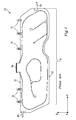
- FIG. 1 schematically illustrates an airbag 10 according to prior art in a flat state, i.e. unrolled but not inflated.
- the airbag 10 has a longitudinal direction x, a depth direction y and a height direction z. These directions coincide with the corresponding directions of a vehicle such as a car, in which the airbag is to be mounted, such that the longitudinal direction x coincides with the length of the vehicle, the depth direction y coincides with the width of the vehicle and the height direction z coincides with the height of the vehicle.
- the airbag 10 comprises a first longitudinal side 12 with fastening means 14 for attaching the airbag 10 to a vehicle cant rail and a second longitudinal side 16 opposite to the first longitudinal side 12.
- the second longitudinal side 16 has a length L 0 in the longitudinal direction x, where the subscript 0 denotes that it is the length in the flat state.
- a front tether 18 may be attached to the vehicle, e.g. to the A-pillar.
- a rear tether 20 may also be attached to the vehicle.
- the terms front and rear relate to the front and rear of the vehicle, in which the airbag 10 is to be mounted.
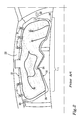
- Figure 2 illustrates the airbag 10 of Figure 1 in an inflated state when mounted in a vehicle.
- the cant rail 22 of the vehicle has a curved shape, which is common in modern vehicles.
- the first longitudinal side 12 is substantially straight in the flat state of the airbag 10.
- the first longitudinal side 12 of the airbag will adapt to the curvature of the cant rail 22 and thus also be curved.
- the longitudinal extension L 1 of the airbag 10 is reduced as compared to the flat state of Figure 1 .
- the curved shape causes a wrinkle 24 to be formed adjacent to the second longitudinal side 16.
- the wrinkle 24 deforms the airbag 10 and makes the airbag 10 contract even more in the longitudinal direction x, thereby further reducing the longitudinal extension L 1 of the airbag 10.
- the longitudinal extension L 1 in the inflated state is thus less than the longitudinal extension L 0 in the flat state.
- the fastening means 14 and the tethers 18, 20 will help to retain the airbag 10 in an extended state in the x direction.
- lower corners 26, 28 will be displaced towards the centre of the airbag 10.
- the airbag 10 may be pulled away from the intended coverage zones.
- the front tether 18 will tend to counteract this displacement.
- the largest displacement will occur at the rear corner 28.
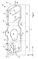
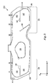
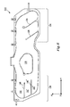
- an airbag 110 according to a first embodiment of the invention is illustrated in a flat state. Similar to the prior art airbag 10 of Figures 1 and 2 , the airbag 110 according to the first embodiment has a longitudinal direction x, a depth direction y and a height direction z and comprises a first longitudinal side 112 with fastening means 114 for attaching the airbag 110 to a vehicle cant rail, and a second longitudinal side 116 opposite to the first longitudinal side 112. A front tether 118 and a rear tether 120 may be attached to the vehicle.
- a circumferential seam 122 along at least a portion of the circumference of the airbag 110 encloses an at least partly inflatable portion of the airbag 110.
- At least a first internal seam 124, 126 within the airbag 110 may be used to control the deployment of the airbag 110, by means of guiding the gas streams of the inflating gas.
- a non-inflatable region 128 within the at least partly inflatable portion of the airbag 110 may be defined by a first internal seam 126, resulting in that not the entire airbag 110 is inflated upon deployment of the airbag 110.
- the non-inflatable region 128 may also be used to control the inflating of the airbag 110 in a similar way as the first internal seams 124, 126.
- an upper channel 130 and a lower channel 132 are formed in the airbag 110 by the non-inflatable region 128.
- the terms upper and lower refer to when the airbag 110 has deployed inside a vehicle.
- the airbag 110 further comprises a first longitudinal end portion 134, a second longitudinal end portion 136, and a central portion 138 therebetween.
- the first longitudinal end portion 134 is in this example located at the front end 140 of the airbag 110 and extends between the front end 140 of the airbag 110 and the location 142 of the seat belt at the B-pillar of the vehicle, here indicated by dashed lines.
- the second longitudinal end portion 136 is located at the rear end 144 of the airbag 110 and extends between the rear end 144 of the airbag 110 and the non-inflatable region 128.
- the central region 138 extends between the first longitudinal end portion 134 and the second longitudinal end portion 136. Each end portion therefore makes up about a third of the longitudinal extension of the airbag 110.
- At least one of the longitudinal end portions here the second longitudinal end portion 136 being at the rear end 144, comprises a second internal seam 146 extending substantially in the longitudinal direction between a first end point 148 adjacent to the circumferential seam 122 and a second end point 150 located longitudinally closer to the centre of the airbag than the first end point 122.
- the second internal seam 146 forms together with a portion of the circumferential seam 122 a longitudinally extending airbag cell 152 below the second internal seam 146.
- an additional longitudinally extending airbag cell 153 is formed above the second internal seam 146.
- the second internal seam 146 has a longitudinal extension L x . If the second internal seam 146 extends substantially straight in the longitudinal direction, the longitudinal extension L x is substantially equal to the length of the second internal seam 146 as illustrated in Figure 3 . However, if the second internal seam 146 is curved or extends at an angle to the longitudinal direction x, its actual length will be greater the longitudinal extension L x .
- the second end point 150 forms the centre of a circle having a radius r, where r is defined as the shortest distance to the most adjacent of any first internal seams 124, 126 or the circumferential seam 122, including the first internal seam forming the non-inflatable region 128. Further, there is a longitudinal distance D x from said second end point 150 of the second internal seam 146 to any of the first internal seams 124, 126. The longitudinal distance D x may coincide with the radius r, but in most cases D x > r.
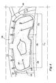
- FIG. 3 illustrates the airbag 110 of Figure 3 in an inflated state when mounted in a vehicle.
- the first longitudinal side 112 of the airbag 110 has adapted to the curvature of the cant rail 156 of the vehicle, such that the inflated airbag 110 also has a curved shape.
- the second internal seam 146 is located at the second longitudinal end portion 136, in this example being the rear longitudinal end portion.
- the second internal seam 146 will thus help to retain the rear end 144 at its intended coverage zone during deployment.
- the airbag cells 152, 153 are filled by substantially longitudinally directed gas streams, the gas stream will help to extend them in the longitudinal direction.
- the airbag cell 152 will help to expand the lower rear corner 158 of the airbag 110. This is especially useful in order to protect a head of a rear seat passenger in case of a side-impact collision, such that the head does not hit the side window behind the airbag.
- Figure 5 illustrates an airbag 210 according to a second embodiment of the invention in a flat state. It has a second internal seam 146, 146' at both longitudinal end portions. Thereby a longitudinally extending airbag cell 152, 152' is formed below the second internal seam 146, 146' in each longitudinal end portion, in a similar way as described above for the first embodiment. These airbag cells 152, 152' will help to expand the lower corners 158, 160 when the airbag 210 is deployed. Further, an additional longitudinally extending airbag cell 153, 153' is formed above the second internal seam 146, 146' at both longitudinal end portions.
- an airbag 310 according to a third embodiment of the invention is illustrated in a flat state. It has two second internal seams 146, 146" at the second end portion.
- the second internal seams 146, 146' may be uniformly distributed in the height direction as illustrated in Figure 6 , or they may be unevenly distributed.
- longitudinally extending airbag cells 152, 152", 153 are formed in a similar way as described above for the first embodiment. These airbag cells will help to expand the second end portion 136 when the airbag 310 is deployed.
- the airbag 310 will contract more in the height direction z at the second end portion as compared to in Figure 4 .
- the extra second internal seams 146" may thus be used in conjunction with a cant rail which is more curved than that of Figure 4 .
- FIG. 7 illustrates an airbag 410 according to a fourth embodiment of the invention in a flat state.
- the airbag 410 has a second internal seam 146 at its second end portion 136, here the rear end portion.
- the width w(x) of the second internal seam 146 varies along its longitudinal extension x, such that the second internal seam 146 is wide at the first end point 148 and narrow at the second end point 150.
- the local contraction of the airbag in the height direction may be influenced.
- the airbag 410 will contract most in the height direction at the rear end 144, since the second internal seam 146 is widest there.
- the width w(x) of the second internal seam 146 may vary in an essentially uniform manner as in Figure 7 , where it has a triangular shape having its base at the rear end 144, or in a non-uniform manner.
- a wide second internal seam 146 may be provided by arranging a seam forming the outer contour of the second internal seam 146 as illustrated in Figure 8 , where the second internal seam 146 comprises two leg seams, a first leg seam 162 and a second leg seam 164.
- the region 166 enclosed by the leg seams 162, 164 is not inflated at deployment of the airbag.
- the enclosed region 166 within the second internal seam 146 may be inflated, for example at a lower rate than the rest of the airbag.
- one or more inflation openings may be provided in at least one of the leg seams 162, 164 (not illustrated).
- the leg seams 162, 164 may be straight or have a curved shape, bending inwards and/or outwards in relation to the enclosed region 166.
- the second internal seam 146 is ended by a more or less round head 168.
- the width at the second end point 150 is in that case determined disregarding the head 168, for example by measuring the width of the second internal seam 146 just before the head 168.
- the circle explained above in conjunction with Figure 3 i.e. the circle having a radius r, where r is defined as the shortest distance to the most adjacent of any first internal seams 124, 126 or the circumferential seam 122, including the first internal seam forming the non-inflatable region 128, is anyway measured from the second end point 150. So is also the longitudinal distance D x of the second internal seam, i.e. the longitudinal distance from the second end point 150 of the second internal seam 146 to any of the at least a first internal seam 124,126.
- one, two, three or more second internal seams may be placed at either or both end portions.
- the number of second internal seams, their lengths, shapes and locations are preferably adapted to the curvature of the cant rail of the vehicle, in which the airbag is to be mounted.
Landscapes
- Engineering & Computer Science (AREA)
- Mechanical Engineering (AREA)
- Air Bags (AREA)
Abstract
Description
- The present disclosure relates to an inflatable airbag according to the preamble of claim 1. The airbag is adapted to deploy in a curtain-like shape over a side surface of a vehicle interior for protecting a vehicle occupant. The disclosure further relates to a vehicle comprising such an inflatable airbag and the use of a second internal seam.
- It is well known within the automobile industry to use inflatable airbags in order to protect vehicle occupants in the event of a vehicle collision. Moreover, it is known to use a curtain airbag which inflates from the cant rail of a vehicle in order to at least partly cover a side surface of the vehicle interior. Such a curtain airbag may provide head protection in side impact collisions. It may also be used for protecting the vehicle occupants in a roll-over situation of the vehicle.
- Document
US 7,740,270 B2 discloses a curtain air bag comprising a main inflation chamber and a sub-inflation chamber which are defined by a partition portion formed by seams inside surfaces of the air bag body, and a gas flow regulation passage formed as a partly non-bonding portion of the partition portion. The main and sub-inflation chambers are respectively located at an upper side and a lower side of the air bag body and communicate with each other through the gas flow regulation passage. The text ofUS 7,740,270 B2 explains that this kind of curtain airbag can help to reduce the peak acceleration exerted on the vehicle occupant. - Normally, the curtain airbag is stored in/at the cant rail of the vehicle roof in a rolled state and is deployed when needed. In modern vehicles the cant rail frequently has a curved shape. In spite of that, most curtain airbags have a straight upper longitudinal edge. Therefore, the airbag may adapt to the shape of the curved cant rail when the airbag is inflated. This will cause the airbag to slightly bend. There is further a risk that one or more wrinkles are created in the airbag, primarily at the lower longitudinal side of the airbag. Both of these phenomena may affect the airbag in such a way that its longitudinal extension is reduced. Thereby the airbag may be pulled away from the intended coverage zones.
- The object of the present disclosure is to overcome or ameliorate at least one of the disadvantages of the prior art, or to provide a useful alternative.
- It is desirable to provide an airbag which may help to reduce the contraction in the longitudinal direction during inflation of the airbag as compared to a prior art airbag.
- It is further desirable that the airbag is not pulled away from the intended coverage zones upon deployment. In particular, it is desirable that the rear lower corner of the airbag upon deployment of the airbag actually covers what it is intended to cover in order to protect the head of a possible rear set occupant.
- The object above may be achieved by the subject-matter of claim 1.
- Thus, in a first aspect of the present disclosure there is provided an inflatable airbag adapted to deploy in a curtain-like shape over a side surface of a vehicle interior for protecting a vehicle occupant. The airbag has a longitudinal, a depth and a height direction. The airbag comprises a first longitudinal end portion, a second longitudinal end portion, and a central portion therebetween having a centre. The airbag further comprises a circumferential seam along substantially its entire circumference, the circumferential seam enclosing an at least partly inflatable portion of the airbag. The airbag further comprises at least a first internal seam, surrounded by the circumferential seam. In addition, the airbag comprises a second internal seam in at least one of the first or second longitudinal end portions. The second internal seam extends substantially in the longitudinal direction between a first end point adjacent to the circumferential seam and a second end point located longitudinally closer to the centre of the airbag than the first end point, the second internal seam together with a portion of the circumferential seam forming a longitudinally extending airbag cell. The second end point is spaced from any of the at least a first internal seam and the circumferential seam by a distance of at least 10 cm, preferably at least 15 cm and most preferably at least 20 cm, such that, when the airbag is deployed, the longitudinally extending airbag cell is pressurized at substantially the same rate as the rest of the inflatable portion of the airbag.
- The term seam is herein used to comprise not only conventional seams, but also welding, thermal bonding, adhesives, clamping or that the airbag has been woven as OWP, i.e. one-piece woven. The term cell denotes herein an airbag structure which has only one in-out passage, while the term channel is used for an airbag structure comprising at least two in-out passages, such that a gas stream may flow through the channel.
- The first longitudinal end portion may be located either at the front or the rear end of the airbag, where front and rear relate to the vehicle, in which the airbag is to be mounted. The second longitudinal end portion is the opposite end portion. Hence, if the first longitudinal end portion is at the front, the second longitudinal end portion is at the rear, and vice versa.
- When inflating the airbag according to the disclosure, the airbag will contract in the height direction as compared to in a flat state, i.e. unrolled but not inflated, since the airbag expands in the depth direction. Moreover, since the second internal seam is arranged in at least one of the longitudinal end portions, the airbag will in that longitudinal end portion contract more in the height direction as compared to a prior art airbag. Therefore, the airbag according to the disclosure may more easily adapt to the shape of a curved cant rail. In addition, the risk of creating a wrinkle is reduced due to the additional height direction contraction. The above-mentioned problem with longitudinal contraction is therefore at least partly counteracted. Hence the risk of pulling the airbag away from the intended coverage zones is reduced. In particular, by locating the at least one longitudinally extending airbag cell at the rear longitudinal end portion, it may be ensured that the rear lower corner of the airbag upon deployment of the airbag actually covers the intended coverage zone in order to protect the head of a possible rear set occupant. In a similar way, a longitudinally extending airbag cell located at the front longitudinal end portion may help to extend the airbag forwards.
- The second internal seam extends substantially in the longitudinal direction of the airbag with a longitudinal extension Lx. It may have a straight or a curved shape. It may extend straight in the longitudinal direction or at an angle to the longitudinal direction. In the latter case, the angle would preferably be between +/-45 degrees from the longitudinal direction, most preferably +/- 30 degrees. If the shape is curved, the angle is measured in relation to a straight line passing through the first and second end points of the second internal seam.
- The longitudinally extending airbag cell constitutes a part of the at least partly inflatable portion of the airbag. Since the portion of the airbag enclosed by the circumferential seam also comprises inner seams and possibly a non-inflatable region, there will be parts of the airbag which are not intended to be inflated and thus the portion of the airbag is partly inflatable. In addition, the airbag may extend outside of the circumferential seam and these areas will not be inflated either. The first end point of the second internal seam may be located in/on the circumferential seam or adjacent to it. One intention of the second internal seam is to form a longitudinally extending airbag cell which is open in the direction towards the rest of the airbag.
- The inflated volume of the longitudinally extending airbag cell may constitute at least 4%, preferably at least 7% and most preferably at least 10% of the inflated volume of the at least partly inflatable portion of the airbag. Thereby the longitudinally extending airbag cell is large enough to influence the behaviour of the airbag upon deployment in such a way that the above-mentioned longitudinal contraction is counteracted in an appropriate manner.
- One, two, three or more second internal seams may be placed at either or both end portions. The number of second internal seams, their lengths, shapes and locations are preferably adapted to the curvature of the cant rail of the vehicle in which the airbag is to be mounted.
- The longitudinally extending airbag cell may be arranged such that, in an inflated state of the airbag, the longitudinally extending airbag cell has a longer extension in the longitudinal direction than in the depth and/or height directions.
- The longitudinally extending airbag cell may be arranged to be filled by a substantially longitudinally directed gas stream during deployment of the airbag. The gas stream will thus help to expand the longitudinally extending airbag cell in the longitudinal direction.
- The inflatable airbag may comprise a first longitudinal side comprising fastening means for attaching the airbag to a vehicle cant rail and a second longitudinal side being opposite to the first longitudinal side when the airbag is deployed, the longitudinally extending airbag cell being located along the second longitudinal side of the airbag, i.e. at the lower part of the deployed airbag. The longitudinally extending airbag cell may then help to expand the rear and/or front lower corners in the longitudinal direction in order to counteract any tendency for the corner to be pulled away from the intended coverage zone upon deployment of the airbag.
- The second internal seam may be located at a height position located between 20% and 80% of the height of the airbag in a flat state, preferably between 30% and 70% and most preferably between 40% and 60%. These numbers relate to the case when one second internal seam is used. If two or more second internal seams are used, they may be distributed over between 20% and 80% of the height.
- A longitudinal distance Dx of the second internal seam may be defined as the distance from the second end point of the second internal seam to any of the at least a first internal seam. The longitudinal distance Dx may be between 50% and 500% of the longitudinal extension Lx of the second internal seam, preferably between 60% and 300% and most preferably between 80% and 150%. The longitudinal distance Dx may be at least 10 cm, preferably at least 15 cm and most preferably at least 20 cm. The longitudinal distance Dx may coincide with the distance r, but in most cases Dx > r.
- The width of the second internal seam may vary along its longitudinal extension, such that the second internal seam is wider at the first end point than at the second end point, for example by having a triangular shape with the base of the triangle going through the first end point. In some cases, an internal seam is ended by a more or less round head; in that case the width at the second end point is determined just before this head. The first end point is defined as being located at half the width of the second internal seam at its end adjacent to the circumferential seam.
- By means of varying the width of the second internal seam, the local contraction of the airbag in the height direction may be influenced. This may be used to adapt the contraction of the airbag in the height direction to the curvature of the cant rail of a vehicle. The width of the second internal seam may vary in an essentially uniform manner, for example having a triangular shape with its base at an end portion, or in a non-uniform manner, for example by means of curved seams.
- The at least one of the first or second longitudinal end portions may comprise one or a plurality of the second internal seam/s. Either one of the first and second longitudinal end portions, or both, may comprise at least one of the second internal seams.
- The inflatable airbag may comprise a non-inflatable region, the longitudinal distance from the second end point of the second internal seam to the non-inflatable region being between 50% and 500% of the longitudinal extension of the second internal seam, preferably between 60% and 300% and most preferably between 80% and 200%. The non-inflatable region is preferably located in the central portion, i. e. the portion in between the first and second longitudinal end portions. Such a non-inflatable region may form an upper channel and a lower channel of the airbag during deployment, thereby controlling the gas flow.
- The airbag may further comprise a gas inlet located at the circumferential seam in a location facing the non-inflatable region.
- The airbag may further comprise at least one tether for connecting the airbag to a part of the vehicle. The tether will help to achieve the desired longitudinal extension of the airbag.
- In a second aspect of the present disclosure, there is provided a vehicle comprising an inflatable airbag as mentioned above, the vehicle comprising a curved cant rail, wherein the second internal seam contracts the inflatable airbag in the height direction during deployment of the airbag, such that the magnitude of the contraction corresponds essentially to the curvature of the cant rail in the height direction. In such a vehicle the above-mentioned problems with longitudinal contraction of the airbag pulling it away from the intended coverage zone and the risk of creating a wrinkle may be at least partly counteracted. The number of second internal seams, their lengths, shapes and locations are preferably adapted to the curvature of the cant rail of the vehicle.
- In a third aspect of the present disclosure there is provided a use of a second internal seam in an inflatable airbag in order to form a longitudinally extending airbag cell, the airbag being adapted to deploy in a curtain-like shape over a side surface of a vehicle interior for protecting a vehicle occupant, and the longitudinally extending airbag cell being adapted to be pressurized at substantially the same rate as the rest of the inflatable portion of the airbag, when the airbag is deployed. The second internal seam contracts the inflatable airbag in the height direction during deployment of the airbag and may therefore prevent the above-mentioned problems with longitudinal contraction of the airbag pulling it away from the intended coverage zone and the risk of creating a wrinkle. The second internal seam may be used to contract the inflatable airbag in the height direction upon deployment of the airbag, such that a first longitudinal side of the airbag achieves a predetermined curvature upon deployment. Such use is especially appropriate in the case that the vehicle, wherein the airbag is mounted or is to be mounted, has a curved cant rail, since the curvature of the deployed airbag thereby may be adapted to the curvature of the cant rail of the vehicle.
- The present invention will hereinafter be further explained by means of non-limiting examples with reference to the appended drawings wherein:
- Fig. 1
- is a schematic drawing of a prior art airbag in a flat state;
- Fig. 2
- is a schematic drawing of the prior art airbag of
Fig. 1 in an inflated state; - Fig. 3
- is a schematic drawing of an airbag according to a first embodiment of the invention in a flat state;
- Fig. 4
- is a schematic drawing of the airbag of
Fig. 3 in an inflated state; - Fig. 5
- is a schematic drawing of an airbag according to a second embodiment of the invention in a flat state;
- Fig. 6
- is a schematic drawing of an airbag according to a third embodiment of the invention in a flat state;
- Fig. 7
- is a schematic drawing of an airbag according to a fourth embodiment of the invention in a flat state; and
- Fig. 8
- is a schematic drawing of an airbag according to a fifth embodiment of the invention in a flat state.
- It should be noted that the appended drawings are not necessarily drawn to scale and that the dimensions of some features of the present invention may have been exaggerated for the sake of clarity.
- The invention will, in the following, be exemplified by embodiments. It should however be realized that the embodiments are included in order to explain principles of the invention and not to limit the scope of the invention, defined by the appended claims. Details from two or more of the embodiments may be combined with each other.
-
Figure 1 schematically illustrates anairbag 10 according to prior art in a flat state, i.e. unrolled but not inflated. Theairbag 10 has a longitudinal direction x, a depth direction y and a height direction z. These directions coincide with the corresponding directions of a vehicle such as a car, in which the airbag is to be mounted, such that the longitudinal direction x coincides with the length of the vehicle, the depth direction y coincides with the width of the vehicle and the height direction z coincides with the height of the vehicle. - The
airbag 10 comprises a firstlongitudinal side 12 with fastening means 14 for attaching theairbag 10 to a vehicle cant rail and a secondlongitudinal side 16 opposite to the firstlongitudinal side 12. The secondlongitudinal side 16 has a length L0 in the longitudinal direction x, where the subscript 0 denotes that it is the length in the flat state. Afront tether 18 may be attached to the vehicle, e.g. to the A-pillar. Arear tether 20 may also be attached to the vehicle. The terms front and rear relate to the front and rear of the vehicle, in which theairbag 10 is to be mounted. -
Figure 2 illustrates theairbag 10 ofFigure 1 in an inflated state when mounted in a vehicle. Thecant rail 22 of the vehicle has a curved shape, which is common in modern vehicles. As can be seen fromFigure 1 , the firstlongitudinal side 12 is substantially straight in the flat state of theairbag 10. However, when theairbag 10 is deployed as seen inFigure 2 , the firstlongitudinal side 12 of the airbag will adapt to the curvature of thecant rail 22 and thus also be curved. As a result of the curved shape, the longitudinal extension L1 of theairbag 10 is reduced as compared to the flat state ofFigure 1 . - In addition, the curved shape causes a
wrinkle 24 to be formed adjacent to the secondlongitudinal side 16. Thewrinkle 24 deforms theairbag 10 and makes theairbag 10 contract even more in the longitudinal direction x, thereby further reducing the longitudinal extension L1 of theairbag 10. The longitudinal extension L1 in the inflated state is thus less than the longitudinal extension L0 in the flat state. Along the firstlongitudinal side 12 the fastening means 14 and thetethers airbag 10 in an extended state in the x direction. However, at the secondlongitudinal side 16,lower corners airbag 10. Thereby, theairbag 10 may be pulled away from the intended coverage zones. At the front end, thefront tether 18 will tend to counteract this displacement. As such, for anairbag 10 like the one exemplified inFigure 2 , the largest displacement will occur at therear corner 28. - In
Figure 3 , anairbag 110 according to a first embodiment of the invention is illustrated in a flat state. Similar to theprior art airbag 10 ofFigures 1 and2 , theairbag 110 according to the first embodiment has a longitudinal direction x, a depth direction y and a height direction z and comprises a firstlongitudinal side 112 with fastening means 114 for attaching theairbag 110 to a vehicle cant rail, and a secondlongitudinal side 116 opposite to the firstlongitudinal side 112. Afront tether 118 and arear tether 120 may be attached to the vehicle. - A
circumferential seam 122 along at least a portion of the circumference of theairbag 110 encloses an at least partly inflatable portion of theairbag 110. At least a firstinternal seam airbag 110 may be used to control the deployment of theairbag 110, by means of guiding the gas streams of the inflating gas. Further, anon-inflatable region 128 within the at least partly inflatable portion of theairbag 110 may be defined by a firstinternal seam 126, resulting in that not theentire airbag 110 is inflated upon deployment of theairbag 110. Thenon-inflatable region 128 may also be used to control the inflating of theairbag 110 in a similar way as the firstinternal seams upper channel 130 and alower channel 132 are formed in theairbag 110 by thenon-inflatable region 128. The terms upper and lower refer to when theairbag 110 has deployed inside a vehicle. - The
airbag 110 further comprises a firstlongitudinal end portion 134, a secondlongitudinal end portion 136, and acentral portion 138 therebetween. The firstlongitudinal end portion 134 is in this example located at thefront end 140 of theairbag 110 and extends between thefront end 140 of theairbag 110 and thelocation 142 of the seat belt at the B-pillar of the vehicle, here indicated by dashed lines. The secondlongitudinal end portion 136 is located at therear end 144 of theairbag 110 and extends between therear end 144 of theairbag 110 and thenon-inflatable region 128. Thecentral region 138 extends between the firstlongitudinal end portion 134 and the secondlongitudinal end portion 136. Each end portion therefore makes up about a third of the longitudinal extension of theairbag 110. - At least one of the longitudinal end portions, here the second
longitudinal end portion 136 being at therear end 144, comprises a secondinternal seam 146 extending substantially in the longitudinal direction between afirst end point 148 adjacent to thecircumferential seam 122 and asecond end point 150 located longitudinally closer to the centre of the airbag than thefirst end point 122. The secondinternal seam 146 forms together with a portion of the circumferential seam 122 a longitudinally extendingairbag cell 152 below the secondinternal seam 146. In a similar way, an additional longitudinally extendingairbag cell 153 is formed above the secondinternal seam 146. - The second
internal seam 146 has a longitudinal extension Lx. If the secondinternal seam 146 extends substantially straight in the longitudinal direction, the longitudinal extension Lx is substantially equal to the length of the secondinternal seam 146 as illustrated inFigure 3 . However, if the secondinternal seam 146 is curved or extends at an angle to the longitudinal direction x, its actual length will be greater the longitudinal extension Lx. - The
second end point 150 forms the centre of a circle having a radius r, where r is defined as the shortest distance to the most adjacent of any firstinternal seams circumferential seam 122, including the first internal seam forming thenon-inflatable region 128. Further, there is a longitudinal distance Dx from saidsecond end point 150 of the secondinternal seam 146 to any of the firstinternal seams - When the
airbag 110 is to be deployed by means of inflation, gas will be injected throughgas inlet 154. In the example ofFigure 3 , thenon-inflatable region 128 is located opposite thegas inlet 154 and helps to direct the gas stream forwards and backwards in the longitudinal direction x. Thereby theairbag cell 152, as well as the additional longitudinally extendingairbag cell 153, are filled by a substantially longitudinally directed gas stream.Figure 4 illustrates theairbag 110 ofFigure 3 in an inflated state when mounted in a vehicle. The firstlongitudinal side 112 of theairbag 110 has adapted to the curvature of thecant rail 156 of the vehicle, such that theinflated airbag 110 also has a curved shape. When inflating theairbag 110, it will contract in the height direction z as compared to in the flat state illustrated inFigure 3 due to it expanding in the depth direction y. Moreover, since the secondinternal seam 146 is arranged in at least one of thelongitudinal end portions airbag 110 will contract even more in the height direction z in this longitudinal end portion due to the secondinternal seam 146. Thereby the above-mentioned longitudinal contraction, explained in conjunction withFigure 2 is at least partly counteracted. Consequently, the risk of pulling thefront end 140 and/or therear end 144 away from the intended coverage zones is decreased. In addition, this may also reduce the risk of wrinkles forming adjacent to the secondlongitudinal side 116. - In the example of
Figures 3 and4 , the secondinternal seam 146 is located at the secondlongitudinal end portion 136, in this example being the rear longitudinal end portion. The secondinternal seam 146 will thus help to retain therear end 144 at its intended coverage zone during deployment. Since theairbag cells airbag cell 152 will help to expand the lowerrear corner 158 of theairbag 110. This is especially useful in order to protect a head of a rear seat passenger in case of a side-impact collision, such that the head does not hit the side window behind the airbag. -
Figure 5 illustrates anairbag 210 according to a second embodiment of the invention in a flat state. It has a secondinternal seam 146, 146' at both longitudinal end portions. Thereby a longitudinally extendingairbag cell 152, 152' is formed below the secondinternal seam 146, 146' in each longitudinal end portion, in a similar way as described above for the first embodiment. Theseairbag cells 152, 152' will help to expand thelower corners airbag 210 is deployed. Further, an additional longitudinally extendingairbag cell 153, 153' is formed above the secondinternal seam 146, 146' at both longitudinal end portions. - In
Figure 6 , anairbag 310 according to a third embodiment of the invention is illustrated in a flat state. It has two secondinternal seams internal seams 146, 146' may be uniformly distributed in the height direction as illustrated inFigure 6 , or they may be unevenly distributed. Thereby longitudinally extendingairbag cells second end portion 136 when theairbag 310 is deployed. By adding an extra secondinternal seam 146" as compared to the first embodiment, theairbag 310 will contract more in the height direction z at the second end portion as compared to inFigure 4 . The extra secondinternal seams 146" may thus be used in conjunction with a cant rail which is more curved than that ofFigure 4 . -
Figure 7 illustrates anairbag 410 according to a fourth embodiment of the invention in a flat state. Theairbag 410 has a secondinternal seam 146 at itssecond end portion 136, here the rear end portion. As can be seen from the figure, the width w(x) of the secondinternal seam 146 varies along its longitudinal extension x, such that the secondinternal seam 146 is wide at thefirst end point 148 and narrow at thesecond end point 150. By means of varying the width w(x) of the secondinternal seam 146, the local contraction of the airbag in the height direction may be influenced. In the illustrated example, theairbag 410 will contract most in the height direction at therear end 144, since the secondinternal seam 146 is widest there. This may be used to adapt the contraction of the airbag in the height direction z to the curvature of the cant rail. The width w(x) of the secondinternal seam 146 may vary in an essentially uniform manner as inFigure 7 , where it has a triangular shape having its base at therear end 144, or in a non-uniform manner. - As an alternative to the second internal seam of
Figure 7 , a wide secondinternal seam 146 may be provided by arranging a seam forming the outer contour of the secondinternal seam 146 as illustrated inFigure 8 , where the secondinternal seam 146 comprises two leg seams, afirst leg seam 162 and asecond leg seam 164. Theregion 166 enclosed by the leg seams 162, 164 is not inflated at deployment of the airbag. As an option, also theenclosed region 166 within the secondinternal seam 146 may be inflated, for example at a lower rate than the rest of the airbag. In that case, one or more inflation openings may be provided in at least one of the leg seams 162, 164 (not illustrated). The leg seams 162, 164 may be straight or have a curved shape, bending inwards and/or outwards in relation to theenclosed region 166. - In some cases, the second
internal seam 146 is ended by a more or lessround head 168. The width at thesecond end point 150 is in that case determined disregarding thehead 168, for example by measuring the width of the secondinternal seam 146 just before thehead 168. However, the circle explained above in conjunction withFigure 3 , i.e. the circle having a radius r, where r is defined as the shortest distance to the most adjacent of any firstinternal seams circumferential seam 122, including the first internal seam forming thenon-inflatable region 128, is anyway measured from thesecond end point 150. So is also the longitudinal distance Dx of the second internal seam, i.e. the longitudinal distance from thesecond end point 150 of the secondinternal seam 146 to any of the at least a first internal seam 124,126. - Further modifications of the invention within the scope of the appended claims are feasible. As such, the present invention should not be considered as limited by the embodiments and figures described herein. Rather, the full scope of the invention should be determined by the appended claims, with reference to the description and drawings.
- In particular, one, two, three or more second internal seams may be placed at either or both end portions. The number of second internal seams, their lengths, shapes and locations are preferably adapted to the curvature of the cant rail of the vehicle, in which the airbag is to be mounted.
Claims (15)
- An inflatable airbag (110) adapted to deploy in a curtain-like shape over a side surface of a vehicle interior for protecting a vehicle occupant,
said airbag (110) having a longitudinal (x), a depth (y) and a height (z) direction, said airbag (110) comprising a first longitudinal end portion (134), a second longitudinal end portion (136), and a central portion (138) therebetween having a centre,
said airbag (110) further comprising a circumferential seam (122) along substantially its entire circumference, said circumferential seam (122) enclosing an at least partly inflatable portion of said airbag (110),
said airbag (110) further comprising at least a first internal seam (124, 126) surrounded by said circumferential seam (122),
characterized in that
said airbag (110) comprises a second internal seam (146) in at least one of said first or second longitudinal end portions (134, 136), said second internal seam (146) extending substantially in said longitudinal direction between a first end point (148) adjacent to said circumferential seam (122) and a second end point (150) located longitudinally closer to said centre of said airbag (110) than said first end point (148), said second internal seam (146) together with a portion of said circumferential seam (122) forming a longitudinally extending airbag cell (152),
said second end point (150) being spaced from any of said at least a first internal seam (124, 126) and said circumferential seam (122) by a distance (r) of at least 10 cm, preferably at least 15 cm and most preferably at least 20 cm, such that, when said airbag (110) is deployed, said longitudinally extending airbag cell (152) is pressurized at substantially the same rate as the rest of said inflatable portion of said airbag (110). - The inflatable airbag (110) according to claim 1, wherein the inflated volume of said longitudinally extending airbag cell (152) constitutes at least 4%, preferably at least 7% and most preferably at least 10% of the inflated volume of said at least partly inflatable portion of said airbag (110).
- The inflatable airbag (110) according to claim 1 or 2, wherein said longitudinally extending airbag cell (152) is arranged such that in an inflated state of said airbag (110), said longitudinally extending airbag cell (152) has a longer extension in said longitudinal direction (x) than in said depth (y) and/or height (z) directions.
- The inflatable airbag (110) according to any one of the preceding claims, wherein said longitudinally extending airbag cell (152) is arranged to be filled by a substantially longitudinally directed gas stream during deployment of said airbag (110).
- The inflatable airbag (110) according to any one of the preceding claims, wherein said airbag (110) comprises a first longitudinal side (112) comprising fastening means (114) for attaching said airbag (110) to a vehicle cant rail and a second longitudinal side (116) being opposite to said first longitudinal side (112) when said airbag (110) is deployed, said longitudinally extending airbag cell (152) being located along said second longitudinal side (116) of said airbag (110).
- The inflatable airbag (110) according to any one of the preceding claims, wherein said second internal seam (146) is located at a height position located between 20% and 80% of the height (h) of the airbag in a flat state, preferably between 30% and 70% and most preferably between 40% and 60%.
- The inflatable airbag (110) according to any one of the preceding claims, wherein a longitudinal distance (Dx) from said second end point (150) of said second internal seam (146) to any of said at least a first internal seam (124, 126) of said airbag (110) is between 50% and 500% of the longitudinal extension (Lx) of said second internal seam (146), preferably between 60% and 300% and most preferably between 80% and 150%.
- The inflatable airbag (110) according to any one of the preceding claims, wherein the width (w(x)) of said second internal seam (146) varies along its longitudinal extension, such that the second internal seam (146) is wider at the first end point (148) than at the second end point (150), for example by having a triangular shape with the base of said triangle going through said first end point (148).
- The inflatable airbag (110) according to any one of the preceding claims, wherein said at least one of said first or second longitudinal end portions (134, 136) comprises a plurality of said second internal seams (146).
- The inflatable airbag (110) according to any one of the preceding claims, wherein both of said first and second longitudinal end portions (134, 136) of said airbag (110) comprise at least one of said second internal seams (146).
- The inflatable airbag (110) according to any one of the preceding claims, wherein said airbag (110) comprises a non-inflatable region (128), the longitudinal distance (Dx) from said second end point (150) of said second internal seam (146) to said non-inflatable region (128), being between 50% and 500% of the longitudinal extension (Lx) of said second internal seam (146), preferably between 60% and 300% and most preferably between 80% and 150%.
- The inflatable airbag (110) according to claim 11, wherein said airbag (110) further comprises a gas inlet (154), said gas inlet (154) being located at said circumferential seam (122) in a location facing said non-inflatable region (128).
- A vehicle comprising an inflatable airbag (110) according to any one of the preceding claims, said vehicle comprising a curved cant rail (156), wherein said second internal seam (146) contracts said inflatable airbag (110) in said height direction (z) during deployment of said airbag, such that the magnitude of said contraction corresponds essentially to the curvature of said cant rail in said height direction (z).
- A use of a second internal seam (146) in an inflatable airbag (110) in order to form a longitudinally extending airbag cell (152) in an at least partly inflatable airbag portion, the airbag (110) being adapted to deploy in a curtain-like shape over a side surface of a vehicle interior for protecting a vehicle occupant and said longitudinally extending airbag cell (152) being adapted to be pressurized at substantially the same rate as the rest of said inflatable portion of said airbag (110), when said airbag (110) is deployed.
- The use of a second internal seam (146) in an inflatable airbag (110) according to claim 14, wherein said second internal seam (146) contracts said inflatable airbag (110) in said height direction (z) upon deployment of said airbag, such that a first longitudinal side (112) of said airbag (110) achieves a predetermined curvature upon deployment.
Priority Applications (1)
| Application Number | Priority Date | Filing Date | Title |
|---|---|---|---|
| EP20110159336 EP2502793B1 (en) | 2011-03-23 | 2011-03-23 | Inflatable airbag |
Applications Claiming Priority (1)
| Application Number | Priority Date | Filing Date | Title |
|---|---|---|---|
| EP20110159336 EP2502793B1 (en) | 2011-03-23 | 2011-03-23 | Inflatable airbag |
Publications (2)
| Publication Number | Publication Date |
|---|---|
| EP2502793A1 true EP2502793A1 (en) | 2012-09-26 |
| EP2502793B1 EP2502793B1 (en) | 2014-05-07 |
Family
ID=44359869
Family Applications (1)
| Application Number | Title | Priority Date | Filing Date |
|---|---|---|---|
| EP20110159336 Active EP2502793B1 (en) | 2011-03-23 | 2011-03-23 | Inflatable airbag |
Country Status (1)
| Country | Link |
|---|---|
| EP (1) | EP2502793B1 (en) |
Cited By (1)
| Publication number | Priority date | Publication date | Assignee | Title |
|---|---|---|---|---|
| KR20190035109A (en) * | 2017-09-26 | 2019-04-03 | 현대모비스 주식회사 | Curtain airbag apparatus |
Citations (3)
| Publication number | Priority date | Publication date | Assignee | Title |
|---|---|---|---|---|
| GB2383304A (en) * | 2001-12-21 | 2003-06-25 | Autoliv Dev | One-piece woven airbag |
| US20060071460A1 (en) * | 2004-08-30 | 2006-04-06 | Nihon Plast Co., Ltd | Curtain air bag for vehicles |
| US20090001694A1 (en) * | 2007-06-28 | 2009-01-01 | Nihon Plast Co., Ltd. | Curtain air bag apparatus |
-
2011
- 2011-03-23 EP EP20110159336 patent/EP2502793B1/en active Active
Patent Citations (4)
| Publication number | Priority date | Publication date | Assignee | Title |
|---|---|---|---|---|
| GB2383304A (en) * | 2001-12-21 | 2003-06-25 | Autoliv Dev | One-piece woven airbag |
| US20060071460A1 (en) * | 2004-08-30 | 2006-04-06 | Nihon Plast Co., Ltd | Curtain air bag for vehicles |
| US20090001694A1 (en) * | 2007-06-28 | 2009-01-01 | Nihon Plast Co., Ltd. | Curtain air bag apparatus |
| US7740270B2 (en) | 2007-06-28 | 2010-06-22 | Nihon Plast Co., Ltd. | Curtain air bag apparatus |
Cited By (1)
| Publication number | Priority date | Publication date | Assignee | Title |
|---|---|---|---|---|
| KR20190035109A (en) * | 2017-09-26 | 2019-04-03 | 현대모비스 주식회사 | Curtain airbag apparatus |
Also Published As
| Publication number | Publication date |
|---|---|
| EP2502793B1 (en) | 2014-05-07 |
Similar Documents
| Publication | Publication Date | Title |
|---|---|---|
| JP6734880B2 (en) | Cost-effective use of integrally molded woven fabrics for curtain airbags | |
| US9610916B2 (en) | Head-protecting airbag device | |
| US8414021B2 (en) | Head-protecting airbag apparatus | |
| US7806433B2 (en) | Head protecting airbag system | |
| JP5656646B2 (en) | Airbag | |
| US8408591B2 (en) | Inflatable curtain airbags with expanded-volume lower portions for ejection mitigation | |
| US8186708B2 (en) | Asymmetric side airbag for improved head and neck protection | |
| US20120049498A1 (en) | Airbag system | |
| US9731676B2 (en) | Curtain airbag device | |
| US7556286B2 (en) | Extended inflatable coverage of inflatable curtains | |
| US9908499B2 (en) | Curtain airbag assembly with stiffening chamber | |
| JP5232422B2 (en) | Side impact airbag, side impact airbag device, vehicle seat | |
| JP5366774B2 (en) | Air bag and air bag folding method | |
| US9415742B1 (en) | Three-way gas guide | |
| CN101927747B (en) | Head protection gasbag device | |
| JP5478219B2 (en) | Airbag | |
| JP5236907B2 (en) | Head protection airbag device | |
| EP2502793B1 (en) | Inflatable airbag | |
| US20060012155A1 (en) | Vehicle side airbag apparatus and seat containing same | |
| JP6129761B2 (en) | Gas guide and airbag device for vehicle airbag | |
| KR102815891B1 (en) | Curtain airbag apparatus for vehicle | |
| CN112292291A (en) | Vehicle occupant protection system with airbag module | |
| KR102557710B1 (en) | Airbag unit of vehicle | |
| JP5634186B2 (en) | Airbag device | |
| JP2009040264A (en) | Head protection airbag device |
Legal Events
| Date | Code | Title | Description |
|---|---|---|---|
| PUAI | Public reference made under article 153(3) epc to a published international application that has entered the european phase |
Free format text: ORIGINAL CODE: 0009012 |
|
| AK | Designated contracting states |
Kind code of ref document: A1 Designated state(s): AL AT BE BG CH CY CZ DE DK EE ES FI FR GB GR HR HU IE IS IT LI LT LU LV MC MK MT NL NO PL PT RO RS SE SI SK SM TR |
|
| AX | Request for extension of the european patent |
Extension state: BA ME |
|
| 17P | Request for examination filed |
Effective date: 20130326 |
|
| 17Q | First examination report despatched |
Effective date: 20130521 |
|
| GRAP | Despatch of communication of intention to grant a patent |
Free format text: ORIGINAL CODE: EPIDOSNIGR1 |
|
| INTG | Intention to grant announced |
Effective date: 20140107 |
|
| GRAS | Grant fee paid |
Free format text: ORIGINAL CODE: EPIDOSNIGR3 |
|
| GRAA | (expected) grant |
Free format text: ORIGINAL CODE: 0009210 |
|
| AK | Designated contracting states |
Kind code of ref document: B1 Designated state(s): AL AT BE BG CH CY CZ DE DK EE ES FI FR GB GR HR HU IE IS IT LI LT LU LV MC MK MT NL NO PL PT RO RS SE SI SK SM TR |
|
| REG | Reference to a national code |
Ref country code: GB Ref legal event code: FG4D |
|
| REG | Reference to a national code |
Ref country code: AT Ref legal event code: REF Ref document number: 666377 Country of ref document: AT Kind code of ref document: T Effective date: 20140515 |
|
| REG | Reference to a national code |
Ref country code: IE Ref legal event code: FG4D |
|
| REG | Reference to a national code |
Ref country code: DE Ref legal event code: R096 Ref document number: 602011006680 Country of ref document: DE Effective date: 20140626 |
|
| REG | Reference to a national code |
Ref country code: SE Ref legal event code: TRGR |
|
| REG | Reference to a national code |
Ref country code: AT Ref legal event code: MK05 Ref document number: 666377 Country of ref document: AT Kind code of ref document: T Effective date: 20140507 |
|
| REG | Reference to a national code |
Ref country code: NL Ref legal event code: VDEP Effective date: 20140507 |
|
| REG | Reference to a national code |
Ref country code: LT Ref legal event code: MG4D |
|
| PG25 | Lapsed in a contracting state [announced via postgrant information from national office to epo] |
Ref country code: GR Free format text: LAPSE BECAUSE OF FAILURE TO SUBMIT A TRANSLATION OF THE DESCRIPTION OR TO PAY THE FEE WITHIN THE PRESCRIBED TIME-LIMIT Effective date: 20140808 Ref country code: IS Free format text: LAPSE BECAUSE OF FAILURE TO SUBMIT A TRANSLATION OF THE DESCRIPTION OR TO PAY THE FEE WITHIN THE PRESCRIBED TIME-LIMIT Effective date: 20140907 Ref country code: NO Free format text: LAPSE BECAUSE OF FAILURE TO SUBMIT A TRANSLATION OF THE DESCRIPTION OR TO PAY THE FEE WITHIN THE PRESCRIBED TIME-LIMIT Effective date: 20140807 Ref country code: FI Free format text: LAPSE BECAUSE OF FAILURE TO SUBMIT A TRANSLATION OF THE DESCRIPTION OR TO PAY THE FEE WITHIN THE PRESCRIBED TIME-LIMIT Effective date: 20140507 Ref country code: LT Free format text: LAPSE BECAUSE OF FAILURE TO SUBMIT A TRANSLATION OF THE DESCRIPTION OR TO PAY THE FEE WITHIN THE PRESCRIBED TIME-LIMIT Effective date: 20140507 Ref country code: CY Free format text: LAPSE BECAUSE OF FAILURE TO SUBMIT A TRANSLATION OF THE DESCRIPTION OR TO PAY THE FEE WITHIN THE PRESCRIBED TIME-LIMIT Effective date: 20140507 |
|
| PG25 | Lapsed in a contracting state [announced via postgrant information from national office to epo] |
Ref country code: LV Free format text: LAPSE BECAUSE OF FAILURE TO SUBMIT A TRANSLATION OF THE DESCRIPTION OR TO PAY THE FEE WITHIN THE PRESCRIBED TIME-LIMIT Effective date: 20140507 Ref country code: HR Free format text: LAPSE BECAUSE OF FAILURE TO SUBMIT A TRANSLATION OF THE DESCRIPTION OR TO PAY THE FEE WITHIN THE PRESCRIBED TIME-LIMIT Effective date: 20140507 Ref country code: PL Free format text: LAPSE BECAUSE OF FAILURE TO SUBMIT A TRANSLATION OF THE DESCRIPTION OR TO PAY THE FEE WITHIN THE PRESCRIBED TIME-LIMIT Effective date: 20140507 Ref country code: ES Free format text: LAPSE BECAUSE OF FAILURE TO SUBMIT A TRANSLATION OF THE DESCRIPTION OR TO PAY THE FEE WITHIN THE PRESCRIBED TIME-LIMIT Effective date: 20140507 Ref country code: AT Free format text: LAPSE BECAUSE OF FAILURE TO SUBMIT A TRANSLATION OF THE DESCRIPTION OR TO PAY THE FEE WITHIN THE PRESCRIBED TIME-LIMIT Effective date: 20140507 Ref country code: RS Free format text: LAPSE BECAUSE OF FAILURE TO SUBMIT A TRANSLATION OF THE DESCRIPTION OR TO PAY THE FEE WITHIN THE PRESCRIBED TIME-LIMIT Effective date: 20140507 |
|
| PG25 | Lapsed in a contracting state [announced via postgrant information from national office to epo] |
Ref country code: PT Free format text: LAPSE BECAUSE OF FAILURE TO SUBMIT A TRANSLATION OF THE DESCRIPTION OR TO PAY THE FEE WITHIN THE PRESCRIBED TIME-LIMIT Effective date: 20140908 |
|
| PG25 | Lapsed in a contracting state [announced via postgrant information from national office to epo] |
Ref country code: BE Free format text: LAPSE BECAUSE OF FAILURE TO SUBMIT A TRANSLATION OF THE DESCRIPTION OR TO PAY THE FEE WITHIN THE PRESCRIBED TIME-LIMIT Effective date: 20140507 Ref country code: SK Free format text: LAPSE BECAUSE OF FAILURE TO SUBMIT A TRANSLATION OF THE DESCRIPTION OR TO PAY THE FEE WITHIN THE PRESCRIBED TIME-LIMIT Effective date: 20140507 Ref country code: EE Free format text: LAPSE BECAUSE OF FAILURE TO SUBMIT A TRANSLATION OF THE DESCRIPTION OR TO PAY THE FEE WITHIN THE PRESCRIBED TIME-LIMIT Effective date: 20140507 Ref country code: RO Free format text: LAPSE BECAUSE OF FAILURE TO SUBMIT A TRANSLATION OF THE DESCRIPTION OR TO PAY THE FEE WITHIN THE PRESCRIBED TIME-LIMIT Effective date: 20140507 Ref country code: DK Free format text: LAPSE BECAUSE OF FAILURE TO SUBMIT A TRANSLATION OF THE DESCRIPTION OR TO PAY THE FEE WITHIN THE PRESCRIBED TIME-LIMIT Effective date: 20140507 Ref country code: CZ Free format text: LAPSE BECAUSE OF FAILURE TO SUBMIT A TRANSLATION OF THE DESCRIPTION OR TO PAY THE FEE WITHIN THE PRESCRIBED TIME-LIMIT Effective date: 20140507 |
|
| REG | Reference to a national code |
Ref country code: DE Ref legal event code: R097 Ref document number: 602011006680 Country of ref document: DE |
|
| PG25 | Lapsed in a contracting state [announced via postgrant information from national office to epo] |
Ref country code: NL Free format text: LAPSE BECAUSE OF FAILURE TO SUBMIT A TRANSLATION OF THE DESCRIPTION OR TO PAY THE FEE WITHIN THE PRESCRIBED TIME-LIMIT Effective date: 20140507 |
|
| PLBE | No opposition filed within time limit |
Free format text: ORIGINAL CODE: 0009261 |
|
| STAA | Information on the status of an ep patent application or granted ep patent |
Free format text: STATUS: NO OPPOSITION FILED WITHIN TIME LIMIT |
|
| 26N | No opposition filed |
Effective date: 20150210 |
|
| PG25 | Lapsed in a contracting state [announced via postgrant information from national office to epo] |
Ref country code: IT Free format text: LAPSE BECAUSE OF FAILURE TO SUBMIT A TRANSLATION OF THE DESCRIPTION OR TO PAY THE FEE WITHIN THE PRESCRIBED TIME-LIMIT Effective date: 20140507 |
|
| REG | Reference to a national code |
Ref country code: DE Ref legal event code: R097 Ref document number: 602011006680 Country of ref document: DE Effective date: 20150210 |
|
| PG25 | Lapsed in a contracting state [announced via postgrant information from national office to epo] |
Ref country code: SI Free format text: LAPSE BECAUSE OF FAILURE TO SUBMIT A TRANSLATION OF THE DESCRIPTION OR TO PAY THE FEE WITHIN THE PRESCRIBED TIME-LIMIT Effective date: 20140507 |
|
| PG25 | Lapsed in a contracting state [announced via postgrant information from national office to epo] |
Ref country code: LU Free format text: LAPSE BECAUSE OF FAILURE TO SUBMIT A TRANSLATION OF THE DESCRIPTION OR TO PAY THE FEE WITHIN THE PRESCRIBED TIME-LIMIT Effective date: 20150323 Ref country code: MC Free format text: LAPSE BECAUSE OF FAILURE TO SUBMIT A TRANSLATION OF THE DESCRIPTION OR TO PAY THE FEE WITHIN THE PRESCRIBED TIME-LIMIT Effective date: 20140507 |
|
| REG | Reference to a national code |
Ref country code: CH Ref legal event code: PL |
|
| REG | Reference to a national code |
Ref country code: FR Ref legal event code: ST Effective date: 20151130 |
|
| REG | Reference to a national code |
Ref country code: IE Ref legal event code: MM4A |
|
| PG25 | Lapsed in a contracting state [announced via postgrant information from national office to epo] |
Ref country code: LI Free format text: LAPSE BECAUSE OF NON-PAYMENT OF DUE FEES Effective date: 20150331 Ref country code: CH Free format text: LAPSE BECAUSE OF NON-PAYMENT OF DUE FEES Effective date: 20150331 Ref country code: IE Free format text: LAPSE BECAUSE OF NON-PAYMENT OF DUE FEES Effective date: 20150323 |
|
| PG25 | Lapsed in a contracting state [announced via postgrant information from national office to epo] |
Ref country code: FR Free format text: LAPSE BECAUSE OF NON-PAYMENT OF DUE FEES Effective date: 20150331 |
|
| PG25 | Lapsed in a contracting state [announced via postgrant information from national office to epo] |
Ref country code: MT Free format text: LAPSE BECAUSE OF FAILURE TO SUBMIT A TRANSLATION OF THE DESCRIPTION OR TO PAY THE FEE WITHIN THE PRESCRIBED TIME-LIMIT Effective date: 20140507 |
|
| PG25 | Lapsed in a contracting state [announced via postgrant information from national office to epo] |
Ref country code: BG Free format text: LAPSE BECAUSE OF FAILURE TO SUBMIT A TRANSLATION OF THE DESCRIPTION OR TO PAY THE FEE WITHIN THE PRESCRIBED TIME-LIMIT Effective date: 20140507 Ref country code: HU Free format text: LAPSE BECAUSE OF FAILURE TO SUBMIT A TRANSLATION OF THE DESCRIPTION OR TO PAY THE FEE WITHIN THE PRESCRIBED TIME-LIMIT; INVALID AB INITIO Effective date: 20110323 Ref country code: SM Free format text: LAPSE BECAUSE OF FAILURE TO SUBMIT A TRANSLATION OF THE DESCRIPTION OR TO PAY THE FEE WITHIN THE PRESCRIBED TIME-LIMIT Effective date: 20140507 |
|
| PG25 | Lapsed in a contracting state [announced via postgrant information from national office to epo] |
Ref country code: TR Free format text: LAPSE BECAUSE OF FAILURE TO SUBMIT A TRANSLATION OF THE DESCRIPTION OR TO PAY THE FEE WITHIN THE PRESCRIBED TIME-LIMIT Effective date: 20140507 |
|
| PG25 | Lapsed in a contracting state [announced via postgrant information from national office to epo] |
Ref country code: MK Free format text: LAPSE BECAUSE OF FAILURE TO SUBMIT A TRANSLATION OF THE DESCRIPTION OR TO PAY THE FEE WITHIN THE PRESCRIBED TIME-LIMIT Effective date: 20140507 |
|
| PG25 | Lapsed in a contracting state [announced via postgrant information from national office to epo] |
Ref country code: AL Free format text: LAPSE BECAUSE OF FAILURE TO SUBMIT A TRANSLATION OF THE DESCRIPTION OR TO PAY THE FEE WITHIN THE PRESCRIBED TIME-LIMIT Effective date: 20140507 |
|
| PGFP | Annual fee paid to national office [announced via postgrant information from national office to epo] |
Ref country code: GB Payment date: 20190311 Year of fee payment: 9 |
|
| PGFP | Annual fee paid to national office [announced via postgrant information from national office to epo] |
Ref country code: SE Payment date: 20190312 Year of fee payment: 9 |
|
| PG25 | Lapsed in a contracting state [announced via postgrant information from national office to epo] |
Ref country code: SE Free format text: LAPSE BECAUSE OF NON-PAYMENT OF DUE FEES Effective date: 20200324 |
|
| GBPC | Gb: european patent ceased through non-payment of renewal fee |
Effective date: 20200323 |
|
| PG25 | Lapsed in a contracting state [announced via postgrant information from national office to epo] |
Ref country code: GB Free format text: LAPSE BECAUSE OF NON-PAYMENT OF DUE FEES Effective date: 20200323 |
|
| P01 | Opt-out of the competence of the unified patent court (upc) registered |
Effective date: 20231212 |
|
| PGFP | Annual fee paid to national office [announced via postgrant information from national office to epo] |
Ref country code: DE Payment date: 20260219 Year of fee payment: 16 |