EP2502684A1 - Apparatus for holding a container - Google Patents
Apparatus for holding a container Download PDFInfo
- Publication number
- EP2502684A1 EP2502684A1 EP11158968A EP11158968A EP2502684A1 EP 2502684 A1 EP2502684 A1 EP 2502684A1 EP 11158968 A EP11158968 A EP 11158968A EP 11158968 A EP11158968 A EP 11158968A EP 2502684 A1 EP2502684 A1 EP 2502684A1
- Authority
- EP
- European Patent Office
- Prior art keywords
- article
- holder
- seating face
- sleeve
- holding
- Prior art date
- Legal status (The legal status is an assumption and is not a legal conclusion. Google has not performed a legal analysis and makes no representation as to the accuracy of the status listed.)
- Ceased
Links
Images

Classifications
-
- B—PERFORMING OPERATIONS; TRANSPORTING
- B25—HAND TOOLS; PORTABLE POWER-DRIVEN TOOLS; MANIPULATORS
- B25B—TOOLS OR BENCH DEVICES NOT OTHERWISE PROVIDED FOR, FOR FASTENING, CONNECTING, DISENGAGING, OR HOLDING
- B25B11/00—Work holders not covered by any preceding group in the subclass, e.g. magnetic work holders, vacuum work holders
- B25B11/005—Vacuum work holders
-
- B—PERFORMING OPERATIONS; TRANSPORTING
- B21—MECHANICAL METAL-WORKING WITHOUT ESSENTIALLY REMOVING MATERIAL; PUNCHING METAL
- B21D—WORKING OR PROCESSING OF SHEET METAL OR METAL TUBES, RODS OR PROFILES WITHOUT ESSENTIALLY REMOVING MATERIAL; PUNCHING METAL
- B21D51/00—Making hollow objects
- B21D51/16—Making hollow objects characterised by the use of the objects
- B21D51/26—Making hollow objects characterised by the use of the objects cans or tins; Closing same in a permanent manner
-
- B—PERFORMING OPERATIONS; TRANSPORTING
- B21—MECHANICAL METAL-WORKING WITHOUT ESSENTIALLY REMOVING MATERIAL; PUNCHING METAL
- B21D—WORKING OR PROCESSING OF SHEET METAL OR METAL TUBES, RODS OR PROFILES WITHOUT ESSENTIALLY REMOVING MATERIAL; PUNCHING METAL
- B21D51/00—Making hollow objects
- B21D51/16—Making hollow objects characterised by the use of the objects
- B21D51/26—Making hollow objects characterised by the use of the objects cans or tins; Closing same in a permanent manner
- B21D51/2692—Manipulating, e.g. feeding and positioning devices; Control systems
Definitions
- This invention relates to an apparatus for holding a container.
- the invention relates to an apparatus and method for holding a container or cup-shaped article such as a metal can body, container lid or closure, whilst performing operations on the sidewall or rim of the container. Examples of such operations include cutting or forming the sidewall or rim of the container or applying a material such as a coating, decoration or lining.
- EP 0853515 B (CROWN CORK & SEAL TECHNOLOGY CORP.) is a blow forming apparatus in which a whole can body is held in a three part movable mould: base, centre and top part while compressed air is introduced to force the can body to conform to the interior profile of the moving mould parts. Whilst this is suitable for forming complex shapes, such shaping requires complex blow forming machinery and is not always be needed for holding a can when carrying out more simple rotational operations.
- US 5694822 (REYNOLDS METALS COMPANY) describes an apparatus for trimming cylindrical can bodies.
- the can bodies are successively mounted with vacuum onto a support mandrel so that the open end portion of the can body projects between an outside circular cutting knife and an inside trimming edge.
- the invention of this patent is said to be less complex than traditional trimmers in which the closed end of the can body is held by vacuum onto a base pad.
- the base pad of the traditional trimmer comprises a holder which has a flat face and a circular centralising feature.
- the holder has holes or channels through which negative air pressure or "suction" is applied. This generally allows the can body to be held concentrically and permits rotational operations to be performed accurately in a plane perpendicular to the longitudinal axis of the article.
- the base of a container such as a beverage can often has a bead or rim portion known as a stand (bead), which stiffens the container and allows it to rest on a flat surface without rocking.
- the container is thus be conveniently held rigidly by a holder using suction onto a flat surface and a seal is formed between the surface and the stand.
- the centralising feature comprises a raised feature, which fits outside the base of the article.
- machine motion often limits the ability to provide a holder of a larger diameter than the container, which constrains the design of the centralising feature.
- seal or grip is lost due to improper seating of the container or cup-shaped article, then manufacturing defects can occur.
- a cutting operation may not cut through the full circumference due to rotation of the container/article on the holder. Sometimes, the cut becomes spiral if the article is lifted away from the holder. If grip is lost in a cap or can flanging or curling operation, an incomplete or uneven flange or curl results. Similarly, if grip is lost in a lining operation, a defective lining is created.
- an apparatus for holding a container or cup-shaped article comprising a holder including a seating face for contacting a base feature or “stand” on the article, and one or more channels for supplying, removing or balancing air pressure such that when suction is applied to the article, the stand is held against the seating face; and a guide profile for guiding the article into the holder; characterised in that the profile guides the stand onto the seating face and comprises additional contact with the article radially outside the seating face; and in that the apparatus includes a concentric outer sleeve which provides the additional radial contact and resists lateral movement of the article whilst maintaining concentricity.
- the sleeve is axially moveable from a position in which the sleeve contacts an outer profile of the article and holds the article concentrically, and a retracted position for release of the article from the seating face.
- the sleeve may also include a conical seal and may include a device to prevent rotation, for example in the form of one or more pin(s).
- a device to prevent rotation for example in the form of one or more pin(s).
- the sleeve is of a rigid material.
- the channels may interconnect from the centre of the holding apparatus to regions between the seating face and the sleeve. Further suction channels may be provided to interconnect from the centre of the holder to regions of the holder below the seating face and the outer sleeve.
- the apparatus may further comprise an orifice plate, which regulates the flow of air to or from the holder, in particular when no article is present.
- a method of holding a cup-shaped article in a concentric position comprising: supplying, removing or balancing air pressure such that when suction is applied to the article, the article is held against a seating face of a holder; and characterised by:
- the method may further comprise moving the outer sleeve into a retracted position and releasing the article from the seating face. This method may involve balancing pressure difference between both sides of the article.
- a step of supplying compressed air may aid release of the article from the seating face.
- the method further comprises regulating the flow of air to or from the holder when no article is present.
- FIG. 1 The side view and partial section of figure 1 shows a prior art apparatus 5 for holding a container such as a drawn cup 1.
- the drawing shows a central region and a cross-hatched, sectioned region of holder 10. Detail is omitted from the central region but it can be seen that there are channels 8 which could be used for the passage of air supply and removal, according to requirements of holding the cup on the holding apparatus 5.
- the central region serves to accommodate the centre of the cup base 2, and in particular to accommodate any shape, button or protrusion on the cup base 2. If the cup base 2 has a recess, the central region of the holder includes circular centralising feature, comprising a raised feature, which fits inside a recess in the recess and holds the cup concentrically.
- the sectioned region 10 of prior art holder 5 includes a support annulus 11, and a seating face 12 at a radially outer part.
- the seating face 12 contacts a stand 3 of the cup 1 as can be seen more clearly in the enlargement of area A, which is shown in figure 2 . From the enlarged view A, it is apparent that the stand 3 contacts annular seating face 12 over substantially all of the radial extent of stand bead 3.
- inclined portion 4 of drawn cup 1 is spaced from shoulder region 14 of the sectioned region 10 of holder 5 by a clear gap "g" such that in this prior art example, the conical shoulder region 14 has a guide function only. Gap "g" extends over the conical shoulder region 14 of sectioned region 10, such that radial movement of the cup 1 is possible when not constrained by negative air pressure or suction (via channels 8, for example).
- the shoulder region 14 in use, when an article is placed into the holder, guides the article and the stand 3 onto annular seating surface 12. Suction holds the cup rigidly on the holder and a seal is formed between the stand and the seating face 12. However, it is still possible for the cup to be resting non-concentrically when the suction is applied.
- the amount of grip is proportional to and limited by three factors: the diameter of the stand where the seal is formed, the area within the seal diameter to which suction is applied and the coefficient of friction between the article and the holder. Other forces applied by the cutting, forming or material application process may also serve to weaken the suction grip.
- a holding apparatus 20 according to a first embodiment of the present invention is shown in figures 3 to 5 .
- the holding apparatus 20 of figures 3 to 5 comprises a central region 22 which serves to accommodate the centre of the cup base 2, and any shape, button or protrusion on the cup base 2.
- the holding apparatus 20 has an independent outer sleeve 25, which is slidable in an axial direction relative to central region 22.
- Figure 3 shows the sleeve in its forward position, in which conical upper edge 24 fully engages and grips inclined portion 4 of drawn cup 1 (best seen from figure 4 ).
- This is in contrast with the holder of the prior art, which as noted above, is always spaced from the inclined portion 4 (see enlarged section of figure 2 ).
- the operation such as cutting or forming imparts a torque on the article and is therefore advantageous that the sleeve of the holder of the present invention grips the article 1.
- Gripping of the article in the present invention is via the sleeve directly on inclined portion 4 of the article and also by a direct seal with a flat seating face 23 at seating diameter D1 of support annulus 26.
- the grip to face 23 is achieved by a suction channel within this face, is applied to the article via channels 28, and grips the article sufficiently to prevent it from rotating.
- the sleeve 25 is in its uppermost position and is spaced from a rear section by gap "G". Without any suction applied, the sleeve lifts the article away from the holder in this position. In its lowermost position (not shown), the sleeve would not contact the article if the article were placed concentrically on the holder.
- Figure 5 shows a sealing element such as O-ring 29, which prevents unwanted ingress of air between the lower end of the sleeve and the holder.
- a sealing element provides a sealing diameter D2 ( figure 3 ).
- the apparatus holds the article tightly with forces both at the stand and the outer profile.
- the axial force F S at the stand equates to the suction pressure multiplied by the area defined by diameter D2.
- the axial force Fp at the outer profile equates to the suction pressure multiplied by the area defined between D3 and D2.
- the resistance to torque provided at the stand is proportional to F S and additional resistance to torque provided at the outer profile is proportional to Fp divided by cosine A.
- FIG. 6 A second embodiment of the invention is shown in figures 6 to 8 .
- the outer sleeve is able to slide to a position, which is level with or below the seating face of the holder. This enables the article to be slid easily into position. Applying suction will raise the outer sleeve into contact with the article to be held, and applying compressed air will lower the outer sleeve to allow the article to be slid into or away from the holder.
Landscapes
- Engineering & Computer Science (AREA)
- Mechanical Engineering (AREA)
- Automation & Control Theory (AREA)
- Hooks, Suction Cups, And Attachment By Adhesive Means (AREA)
- Sealing Of Jars (AREA)
- Automatic Analysis And Handling Materials Therefor (AREA)
- Filling Of Jars Or Cans And Processes For Cleaning And Sealing Jars (AREA)
- Closing Of Containers (AREA)
Abstract
The apparatus comprises holder (20) with a seating face on which a container such as a cup-shaped article stands (1). Air is supplied through channels and air pressure is balanced so as to hold the article (1) against the face. The profile of the apparatus guides a base feature or "stand" of the article (1) into the holder (20) and onto the seating face (23), and contacts the article radially outside the seating face (23). The apparatus also has a concentric outer sleeve (25) to provide the additional radial contact and resist lateral movement of the article (1) while maintaining concentricity.
Description
- This invention relates to an apparatus for holding a container. In particular, but not exclusively, the invention relates to an apparatus and method for holding a container or cup-shaped article such as a metal can body, container lid or closure, whilst performing operations on the sidewall or rim of the container. Examples of such operations include cutting or forming the sidewall or rim of the container or applying a material such as a coating, decoration or lining.
-
EP 0853515 B (CROWN CORK & SEAL TECHNOLOGY CORP.) is a blow forming apparatus in which a whole can body is held in a three part movable mould: base, centre and top part while compressed air is introduced to force the can body to conform to the interior profile of the moving mould parts. Whilst this is suitable for forming complex shapes, such shaping requires complex blow forming machinery and is not always be needed for holding a can when carrying out more simple rotational operations. -
US 5694822 (REYNOLDS METALS COMPANY) describes an apparatus for trimming cylindrical can bodies. The can bodies are successively mounted with vacuum onto a support mandrel so that the open end portion of the can body projects between an outside circular cutting knife and an inside trimming edge. The invention of this patent is said to be less complex than traditional trimmers in which the closed end of the can body is held by vacuum onto a base pad. The base pad of the traditional trimmer comprises a holder which has a flat face and a circular centralising feature. The holder has holes or channels through which negative air pressure or "suction" is applied. This generally allows the can body to be held concentrically and permits rotational operations to be performed accurately in a plane perpendicular to the longitudinal axis of the article. - Although considered by Reynolds to be over-complex, this method of holding can bodies or shallower cup-shaped articles is well suited to high-speed manufacturing equipment. In such equipment, containers are loaded onto and unloaded from holders at high speed. The application of suction is sometimes complemented by the application of small amounts of compressed air when releasing the container.
- The base of a container such as a beverage can often has a bead or rim portion known as a stand (bead), which stiffens the container and allows it to rest on a flat surface without rocking. The container is thus be conveniently held rigidly by a holder using suction onto a flat surface and a seal is formed between the surface and the stand.
- It is also known to provide a raised feature on the face of the holder, which fits within a recess in the base of the container and provides a circular centralising feature. If there is no suitable recess in the base of the container or cup-shaped article, the centralising feature comprises a raised feature, which fits outside the base of the article. However, machine motion often limits the ability to provide a holder of a larger diameter than the container, which constrains the design of the centralising feature.
- Due to the variability in manufacturing processes, it is often necessary to allow a radial clearance between the container or cup-shaped article and the centralising feature. Without this clearance, the container can fail to seat properly on the flat face, and this may impair the seal or cause it to rock on the holder. Unfortunately, this clearance can lead to non-concentrical holding of the container or article and allows sideways/radial movement of the article.
- If seal or grip is lost due to improper seating of the container or cup-shaped article, then manufacturing defects can occur. For example, a cutting operation may not cut through the full circumference due to rotation of the container/article on the holder. Sometimes, the cut becomes spiral if the article is lifted away from the holder. If grip is lost in a cap or can flanging or curling operation, an incomplete or uneven flange or curl results. Similarly, if grip is lost in a lining operation, a defective lining is created.
- This invention seeks to provide a holder, which addresses these problems. In the following text, which relates to the present patent application, expressions such as "container" or "cup-shaped article" are used interchangeably and are intended to cover a wide variety of items, including lids, closures and metal can bodies. Use of either expression is not intended to be limiting or to exclude equivalents or standard alternatives in the packaging trade.
- According to the present invention, there is provided an apparatus for holding a container or cup-shaped article, the apparatus comprising a holder including a seating face for contacting a base feature or "stand" on the article, and one or more channels for supplying, removing or balancing air pressure such that when suction is applied to the article, the stand is held against the seating face; and a guide profile for guiding the article into the holder; characterised in that the profile guides the stand onto the seating face and comprises additional contact with the article radially outside the seating face; and in that the apparatus includes a concentric outer sleeve which provides the additional radial contact and resists lateral movement of the article whilst maintaining concentricity.
- In a preferred embodiment, the sleeve is axially moveable from a position in which the sleeve contacts an outer profile of the article and holds the article concentrically, and a retracted position for release of the article from the seating face.
- The sleeve may also include a conical seal and may include a device to prevent rotation, for example in the form of one or more pin(s). In order to provide accurate holding of the article and to avoid wear, it is preferred that the sleeve is of a rigid material.
- Generally, the channels may interconnect from the centre of the holding apparatus to regions between the seating face and the sleeve. Further suction channels may be provided to interconnect from the centre of the holder to regions of the holder below the seating face and the outer sleeve.
- The apparatus may further comprise an orifice plate, which regulates the flow of air to or from the holder, in particular when no article is present.
- According to another aspect of the present invention, there is provided a method of holding a cup-shaped article in a concentric position, the method comprising: supplying, removing or balancing air pressure such that when suction is applied to the article, the article is held against a seating face of a holder; and characterised by:
- preventing radial movement of the article with a concentric outer sleeve and thereby maintaining concentricity of the article.
- The method may further comprise moving the outer sleeve into a retracted position and releasing the article from the seating face. This method may involve balancing pressure difference between both sides of the article.
- A step of supplying compressed air may aid release of the article from the seating face.
- Ideally, the method further comprises regulating the flow of air to or from the holder when no article is present.
- Preferred embodiments of the present invention will now be described, by way of example only, with reference to the drawings, in which:
-
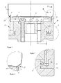
Figure 1 is a side view of a prior art device for holding a container; -
Figure 2 is enlarged view A offigure 1 ; -
Figure 3 is a side view with partial side section of a holding apparatus according to a first embodiment of the invention; -
Figure 4 is enlarged view B offigure 3 ; -
Figure 5 is enlarged view C offigure 3 ; -
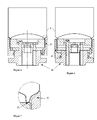
Figure 6 is a side view with partial side section of a holding apparatus in a first sleeve position according to a second embodiment of the invention; -
Figure 7 is enlarged view C offigure 6 ; and -
Figure 8 is a side view with partial side section of a holding apparatus in a second sleeve position according to the second embodiment of the invention. - The side view and partial section of
figure 1 shows aprior art apparatus 5 for holding a container such as a drawncup 1. The drawing shows a central region and a cross-hatched, sectioned region ofholder 10. Detail is omitted from the central region but it can be seen that there are channels 8 which could be used for the passage of air supply and removal, according to requirements of holding the cup on theholding apparatus 5. - The central region serves to accommodate the centre of the
cup base 2, and in particular to accommodate any shape, button or protrusion on thecup base 2. If thecup base 2 has a recess, the central region of the holder includes circular centralising feature, comprising a raised feature, which fits inside a recess in the recess and holds the cup concentrically. - The sectioned
region 10 ofprior art holder 5 includes asupport annulus 11, and aseating face 12 at a radially outer part. Theseating face 12 contacts a stand 3 of thecup 1 as can be seen more clearly in the enlargement of area A, which is shown infigure 2 . From the enlarged view A, it is apparent that the stand 3 contactsannular seating face 12 over substantially all of the radial extent of stand bead 3. However,inclined portion 4 of drawncup 1 is spaced fromshoulder region 14 of the sectionedregion 10 ofholder 5 by a clear gap "g" such that in this prior art example, theconical shoulder region 14 has a guide function only. Gap "g" extends over theconical shoulder region 14 of sectionedregion 10, such that radial movement of thecup 1 is possible when not constrained by negative air pressure or suction (via channels 8, for example). - The
shoulder region 14, in use, when an article is placed into the holder, guides the article and the stand 3 ontoannular seating surface 12. Suction holds the cup rigidly on the holder and a seal is formed between the stand and theseating face 12. However, it is still possible for the cup to be resting non-concentrically when the suction is applied. - The amount of grip is proportional to and limited by three factors: the diameter of the stand where the seal is formed, the area within the seal diameter to which suction is applied and the coefficient of friction between the article and the holder. Other forces applied by the cutting, forming or material application process may also serve to weaken the suction grip.
- A holding
apparatus 20 according to a first embodiment of the present invention is shown infigures 3 to 5 . Similarly to the prior art holder offigures 1 and 2 , the holdingapparatus 20 offigures 3 to 5 comprises acentral region 22 which serves to accommodate the centre of thecup base 2, and any shape, button or protrusion on thecup base 2. - In contrast to the prior art, however, the holding
apparatus 20 has an independentouter sleeve 25, which is slidable in an axial direction relative tocentral region 22.Figure 3 shows the sleeve in its forward position, in which conical upper edge 24 fully engages and gripsinclined portion 4 of drawn cup 1 (best seen fromfigure 4 ). This is in contrast with the holder of the prior art, which as noted above, is always spaced from the inclined portion 4 (see enlarged section offigure 2 ). - Often the operation such as cutting or forming imparts a torque on the article and is therefore advantageous that the sleeve of the holder of the present invention grips the
article 1. Gripping of the article in the present invention is via the sleeve directly oninclined portion 4 of the article and also by a direct seal with aflat seating face 23 at seating diameter D1 ofsupport annulus 26. The grip to face 23 is achieved by a suction channel within this face, is applied to the article viachannels 28, and grips the article sufficiently to prevent it from rotating. - As shown in
figures 3 and 5 , thesleeve 25 is in its uppermost position and is spaced from a rear section by gap "G". Without any suction applied, the sleeve lifts the article away from the holder in this position. In its lowermost position (not shown), the sleeve would not contact the article if the article were placed concentrically on the holder. -
Figure 5 shows a sealing element such as O-ring 29, which prevents unwanted ingress of air between the lower end of the sleeve and the holder. Such a sealing element provides a sealing diameter D2 (figure 3 ). - When an article corresponding to the dimensions of the holder and sleeve is positioned on the apparatus and suction is applied, contact between the apparatus and the article forms a seal and the article is pulled against the apparatus by suction. The stand of the article is pulled to the face of the holder and the sleeve is pulled to contact the outer profile of the article at a sealing diameter D3 and at an angle A normal to the axis, so that the article is held concentrically within the apparatus.
- Thus, in the embodiment of
figures 3 to 5 , the apparatus holds the article tightly with forces both at the stand and the outer profile. The axial force F S at the stand equates to the suction pressure multiplied by the area defined by diameter D2. The axial force Fp at the outer profile equates to the suction pressure multiplied by the area defined between D3 and D2. The resistance to torque provided at the stand is proportional to FS and additional resistance to torque provided at the outer profile is proportional to Fp divided by cosine A. In the event that the article is pulled away from the seating face of a holder, the forces applied by the sleeve will increase to resist slippage and restore seating. - A second embodiment of the invention is shown in
figures 6 to 8 . In this embodiment, the outer sleeve is able to slide to a position, which is level with or below the seating face of the holder. This enables the article to be slid easily into position. Applying suction will raise the outer sleeve into contact with the article to be held, and applying compressed air will lower the outer sleeve to allow the article to be slid into or away from the holder. -
- 1
- drawn cup
- 2
- cup base
- 3
- stand
- 4
- inclined cup portion
- 5
- prior art holder/ holding apparatus
- 7
- central region
- 8
- channels
- 10
- sectioned region of holder
- 11
- support annulus
- 12
- seating face
- 14
- (conical) shoulder region
-
- 20
- holding
apparatus 1st embodiment - 22
- central region
- 23
- seating face
- 24
- conical upper edge
- 25
- outer sleeve
- 26
- support annulus
- 28
- channels
- 29
- 'O' ring
-
- 30
- holding
apparatus 2nd embodiment - 33
- seating face
- 35
- outer sleeve
Claims (12)
- An apparatus for holding a container or cup-shaped article, the apparatus comprising:a holder including a seating face for contacting a base feature or "stand" on the article, and one or more channels for supplying, removing or balancing air pressure such that when suction is applied to the article, the stand is held against the face; and a guide profile for guiding the article into the holder;characterised in that the profile guides the stand onto the seating face and comprises additional contact with the article radially outside the seating face; and in thatthe apparatus includes a concentric outer sleeve which provides the additional radial contact and resists lateral movement of the article whilst maintaining concentricity.
- An apparatus according to claim 1, in which the sleeve is axially moveable from a position in which the sleeve contacts an outer profile of the article and holds the article concentrically, and a retracted position for release of the article from the seating face.
- An apparatus according to claim 1 or claim 2, further including a conical seal on the sleeve.
- An apparatus according to any one of claims 1 to 3, in which the sleeve includes a device to prevent rotation.
- An apparatus according to claim 4, in which the gripping device comprises one or more pin(s).
- An apparatus according to any one of claims 1 to 5, in which the channels interconnect from the centre of the holding apparatus to regions between the seating face and the sleeve.
- An apparatus according to any one of claims 1 to 6, further comprising an orifice plate which regulates the flow of air to or from the holder when no article is present to be held.
- A method of holding a cup-shaped article in a concentric position, the method comprising: supplying, removing or balancing air pressure such that when suction is applied to the article, the article is held against a seating face of a holder; and characterised by:preventing radial movement of the article with a concentric outer sleeve andthereby maintaining concentricity of the article.
- A method according to claim 8, further comprising moving the outer sleeve into a retracted position and releasing the article from the seating face.
- A method according to claim 9 comprising balancing pressure difference between both sides of the article.
- A method according to claim 9 or claim 10, further comprising supplying compressed air to aid release of the article from the seating face.
- A method according to any one of claims 8 to 11, further comprising regulating the flow of air to or from the holder when no article is present.
Priority Applications (10)
| Application Number | Priority Date | Filing Date | Title |
|---|---|---|---|
| EP11158968A EP2502684A1 (en) | 2011-03-21 | 2011-03-21 | Apparatus for holding a container |
| PL12707753T PL2688695T3 (en) | 2011-03-21 | 2012-03-06 | Apparatus for holding a container |
| EP12707753.5A EP2688695B1 (en) | 2011-03-21 | 2012-03-06 | Apparatus for holding a container |
| CA2830315A CA2830315C (en) | 2011-03-21 | 2012-03-06 | Apparatus for holding a container |
| PCT/EP2012/053826 WO2012126723A1 (en) | 2011-03-21 | 2012-03-06 | Apparatus for holding a container |
| US14/006,210 US9364938B2 (en) | 2011-03-21 | 2012-03-06 | Apparatus for holding a container |
| MX2013010767A MX343710B (en) | 2011-03-21 | 2012-03-06 | Apparatus for holding a container. |
| AU2012230555A AU2012230555B2 (en) | 2011-03-21 | 2012-03-06 | Apparatus for holding a container |
| HUE12707753A HUE041540T2 (en) | 2011-03-21 | 2012-03-06 | Apparatus for holding a container |
| ES12707753.5T ES2689260T3 (en) | 2011-03-21 | 2012-03-06 | Apparatus for supporting a container |
Applications Claiming Priority (1)
| Application Number | Priority Date | Filing Date | Title |
|---|---|---|---|
| EP11158968A EP2502684A1 (en) | 2011-03-21 | 2011-03-21 | Apparatus for holding a container |
Publications (1)
| Publication Number | Publication Date |
|---|---|
| EP2502684A1 true EP2502684A1 (en) | 2012-09-26 |
Family
ID=44461802
Family Applications (2)
| Application Number | Title | Priority Date | Filing Date |
|---|---|---|---|
| EP11158968A Ceased EP2502684A1 (en) | 2011-03-21 | 2011-03-21 | Apparatus for holding a container |
| EP12707753.5A Active EP2688695B1 (en) | 2011-03-21 | 2012-03-06 | Apparatus for holding a container |
Family Applications After (1)
| Application Number | Title | Priority Date | Filing Date |
|---|---|---|---|
| EP12707753.5A Active EP2688695B1 (en) | 2011-03-21 | 2012-03-06 | Apparatus for holding a container |
Country Status (9)
| Country | Link |
|---|---|
| US (1) | US9364938B2 (en) |
| EP (2) | EP2502684A1 (en) |
| AU (1) | AU2012230555B2 (en) |
| CA (1) | CA2830315C (en) |
| ES (1) | ES2689260T3 (en) |
| HU (1) | HUE041540T2 (en) |
| MX (1) | MX343710B (en) |
| PL (1) | PL2688695T3 (en) |
| WO (1) | WO2012126723A1 (en) |
Cited By (1)
| Publication number | Priority date | Publication date | Assignee | Title |
|---|---|---|---|---|
| US20140008856A1 (en) * | 2011-03-21 | 2014-01-09 | Crown Packaging Technology, Inc. | Apparatus for holding a container |
Families Citing this family (3)
| Publication number | Priority date | Publication date | Assignee | Title |
|---|---|---|---|---|
| ITVR20110229A1 (en) * | 2011-12-22 | 2013-06-23 | Spl Soluzioni S R L | GRIPPING DEVICE FOR LOCKING CYLINDRICAL METAL CONTAINERS INTENDED FOR WORKING THROUGH OPERATING MACHINES |
| JP1583595S (en) * | 2017-01-30 | 2017-08-14 | ||
| JP1583839S (en) * | 2017-02-28 | 2017-08-14 |
Citations (6)
| Publication number | Priority date | Publication date | Assignee | Title |
|---|---|---|---|---|
| GB575923A (en) * | 1944-09-01 | 1946-03-11 | Claude Spencer Harris | Improvements in and relating to vacuum chucks or work holders |
| GB601485A (en) * | 1945-10-03 | 1948-05-06 | Midland Metal Spinning Company | Improvements in or relating to suction-operated chucks |
| US3628451A (en) * | 1969-05-23 | 1971-12-21 | Reynolds Metals Co | Apparatus for and method of shaping workpieces |
| US4781047A (en) * | 1983-10-14 | 1988-11-01 | Ball Corporation | Controlled spin flow forming |
| US5694822A (en) | 1993-08-16 | 1997-12-09 | Reynolds Metals Company | Apparatus for trimming can bodies |
| EP0853515B1 (en) | 1995-10-02 | 2001-10-31 | Crown Cork & Seal Technologies Corporation | Systems and methods for making decorative shaped metal cans |
Family Cites Families (10)
| Publication number | Priority date | Publication date | Assignee | Title |
|---|---|---|---|---|
| US3383808A (en) * | 1965-05-25 | 1968-05-21 | Lunette De Paris Inc | Lens block |
| US3833230A (en) * | 1973-09-13 | 1974-09-03 | Corning Glass Works | Vacuum chuck |
| US4316375A (en) * | 1979-11-30 | 1982-02-23 | Reynolds Metals Company | Apparatus for corrugating can body flanges |
| US4266685A (en) * | 1979-11-30 | 1981-05-12 | Reynolds Metals Company | Can body and method for making same |
| US5348316A (en) * | 1992-07-16 | 1994-09-20 | National Semiconductor Corporation | Die collet with cavity wall recess |
| US6237388B1 (en) * | 2000-03-08 | 2001-05-29 | Can Industry Products, Inc. | Transfer apparatus and method for transferring container bodies in a press |
| KR101462702B1 (en) * | 2007-06-13 | 2014-11-17 | 프라티니 에스.피.에이. 코스트루찌오니 메카니체 | A gripping and handling device for metal containers |
| GB2471712A (en) * | 2009-07-10 | 2011-01-12 | De Beers Centenary AG | Gemstone alignment system |
| EP2502684A1 (en) * | 2011-03-21 | 2012-09-26 | Crown Packaging Technology Inc | Apparatus for holding a container |
| US20130255453A1 (en) * | 2012-04-02 | 2013-10-03 | Jensen Buck | Vacuum blocking for manufacturing optical devices |
-
2011
- 2011-03-21 EP EP11158968A patent/EP2502684A1/en not_active Ceased
-
2012
- 2012-03-06 EP EP12707753.5A patent/EP2688695B1/en active Active
- 2012-03-06 MX MX2013010767A patent/MX343710B/en active IP Right Grant
- 2012-03-06 WO PCT/EP2012/053826 patent/WO2012126723A1/en not_active Ceased
- 2012-03-06 AU AU2012230555A patent/AU2012230555B2/en active Active
- 2012-03-06 PL PL12707753T patent/PL2688695T3/en unknown
- 2012-03-06 CA CA2830315A patent/CA2830315C/en not_active Expired - Fee Related
- 2012-03-06 ES ES12707753.5T patent/ES2689260T3/en active Active
- 2012-03-06 US US14/006,210 patent/US9364938B2/en active Active
- 2012-03-06 HU HUE12707753A patent/HUE041540T2/en unknown
Patent Citations (6)
| Publication number | Priority date | Publication date | Assignee | Title |
|---|---|---|---|---|
| GB575923A (en) * | 1944-09-01 | 1946-03-11 | Claude Spencer Harris | Improvements in and relating to vacuum chucks or work holders |
| GB601485A (en) * | 1945-10-03 | 1948-05-06 | Midland Metal Spinning Company | Improvements in or relating to suction-operated chucks |
| US3628451A (en) * | 1969-05-23 | 1971-12-21 | Reynolds Metals Co | Apparatus for and method of shaping workpieces |
| US4781047A (en) * | 1983-10-14 | 1988-11-01 | Ball Corporation | Controlled spin flow forming |
| US5694822A (en) | 1993-08-16 | 1997-12-09 | Reynolds Metals Company | Apparatus for trimming can bodies |
| EP0853515B1 (en) | 1995-10-02 | 2001-10-31 | Crown Cork & Seal Technologies Corporation | Systems and methods for making decorative shaped metal cans |
Cited By (2)
| Publication number | Priority date | Publication date | Assignee | Title |
|---|---|---|---|---|
| US20140008856A1 (en) * | 2011-03-21 | 2014-01-09 | Crown Packaging Technology, Inc. | Apparatus for holding a container |
| US9364938B2 (en) * | 2011-03-21 | 2016-06-14 | Crown Packaging Technology, Inc. | Apparatus for holding a container |
Also Published As
| Publication number | Publication date |
|---|---|
| MX343710B (en) | 2016-11-18 |
| ES2689260T3 (en) | 2018-11-12 |
| MX2013010767A (en) | 2013-10-17 |
| EP2688695A1 (en) | 2014-01-29 |
| EP2688695B1 (en) | 2018-07-04 |
| CA2830315C (en) | 2019-02-26 |
| US9364938B2 (en) | 2016-06-14 |
| CA2830315A1 (en) | 2012-09-27 |
| PL2688695T3 (en) | 2018-11-30 |
| HUE041540T2 (en) | 2019-05-28 |
| US20140008856A1 (en) | 2014-01-09 |
| WO2012126723A1 (en) | 2012-09-27 |
| AU2012230555B2 (en) | 2017-01-12 |
| AU2012230555A1 (en) | 2013-09-12 |
Similar Documents
| Publication | Publication Date | Title |
|---|---|---|
| AU2012244852B2 (en) | Method for forming a metal closure | |
| RU2619414C2 (en) | Pusher for use in metal vessel neck forming, stamping system of metal vessel neck forming and method of metal vessel neck forming | |
| EP2688695B1 (en) | Apparatus for holding a container | |
| KR101388292B1 (en) | Process and apparatus to make an edge or a collar featuring a complex structure on metal rough pieces | |
| US7503741B2 (en) | Formation of a curl in a unitary closable container | |
| US8671730B2 (en) | Method and apparatus for making a can with a curled end, such can and body | |
| KR20170141727A (en) | Method and apparatus for curling an article | |
| RS56354B1 (en) | Draw and iron apparatus | |
| EP2190605B8 (en) | A gripping and handling device for metal containers | |
| EP0017434B1 (en) | Cup-shaped containers and method and apparatus for manufacturing them | |
| JP2018099729A (en) | Manufacturing method of can | |
| KR20070089842A (en) | Devices for selectively and progressively fixing metal containers | |
| JP2024129797A (en) | Can lid manufacturing device, can lid manufacturing method, can lid, and can container with contents | |
| JP7207873B2 (en) | Bottle can manufacturing method | |
| JP2008013210A (en) | Capping method and apparatus | |
| JP2005145522A (en) | Capping method and apparatus | |
| JP2018089691A (en) | Bottle can manufacturing apparatus | |
| JP6689687B2 (en) | Can manufacturing method | |
| JP2025537564A (en) | How to make an aerosol dome | |
| JPH0787957B2 (en) | Neck-in part forming method and device | |
| JP2006150426A (en) | Can body manufacturing apparatus and can body manufacturing method |
Legal Events
| Date | Code | Title | Description |
|---|---|---|---|
| PUAI | Public reference made under article 153(3) epc to a published international application that has entered the european phase |
Free format text: ORIGINAL CODE: 0009012 |
|
| AK | Designated contracting states |
Kind code of ref document: A1 Designated state(s): AL AT BE BG CH CY CZ DE DK EE ES FI FR GB GR HR HU IE IS IT LI LT LU LV MC MK MT NL NO PL PT RO RS SE SI SK SM TR |
|
| AX | Request for extension of the european patent |
Extension state: BA ME |
|
| STAA | Information on the status of an ep patent application or granted ep patent |
Free format text: STATUS: THE APPLICATION HAS BEEN REFUSED |
|
| 18R | Application refused |
Effective date: 20121015 |