EP2502581A1 - Pneumatic surgical instrument and corresponding methods for penetrating, resecting and microfracturing bone - Google Patents
Pneumatic surgical instrument and corresponding methods for penetrating, resecting and microfracturing bone Download PDFInfo
- Publication number
- EP2502581A1 EP2502581A1 EP20120356005 EP12356005A EP2502581A1 EP 2502581 A1 EP2502581 A1 EP 2502581A1 EP 20120356005 EP20120356005 EP 20120356005 EP 12356005 A EP12356005 A EP 12356005A EP 2502581 A1 EP2502581 A1 EP 2502581A1
- Authority
- EP
- European Patent Office
- Prior art keywords
- probe
- instrument
- bone
- surgical instrument
- distal end
- Prior art date
- Legal status (The legal status is an assumption and is not a legal conclusion. Google has not performed a legal analysis and makes no representation as to the accuracy of the status listed.)
- Granted
Links
Images



Classifications
-
- A—HUMAN NECESSITIES
- A61—MEDICAL OR VETERINARY SCIENCE; HYGIENE
- A61B—DIAGNOSIS; SURGERY; IDENTIFICATION
- A61B17/00—Surgical instruments, devices or methods
- A61B17/56—Surgical instruments or methods for treatment of bones or joints; Devices specially adapted therefor
- A61B17/58—Surgical instruments or methods for treatment of bones or joints; Devices specially adapted therefor for osteosynthesis, e.g. bone plates, screws or setting implements
- A61B17/88—Osteosynthesis instruments; Methods or means for implanting or extracting internal or external fixation devices
- A61B17/92—Impactors or extractors, e.g. for removing intramedullary devices
-
- A—HUMAN NECESSITIES
- A61—MEDICAL OR VETERINARY SCIENCE; HYGIENE
- A61F—FILTERS IMPLANTABLE INTO BLOOD VESSELS; PROSTHESES; DEVICES PROVIDING PATENCY TO, OR PREVENTING COLLAPSING OF, TUBULAR STRUCTURES OF THE BODY, e.g. STENTS; ORTHOPAEDIC, NURSING OR CONTRACEPTIVE DEVICES; FOMENTATION; TREATMENT OR PROTECTION OF EYES OR EARS; BANDAGES, DRESSINGS OR ABSORBENT PADS; FIRST-AID KITS
- A61F2/00—Filters implantable into blood vessels; Prostheses, i.e. artificial substitutes or replacements for parts of the body; Appliances for connecting them with the body; Devices providing patency to, or preventing collapsing of, tubular structures of the body, e.g. stents
- A61F2/02—Prostheses implantable into the body
- A61F2/30—Joints
- A61F2/46—Special tools for implanting artificial joints
- A61F2/4603—Special tools for implanting artificial joints for insertion or extraction of endoprosthetic joints or of accessories thereof
- A61F2/4607—Special tools for implanting artificial joints for insertion or extraction of endoprosthetic joints or of accessories thereof of hip femoral endoprostheses
-
- A—HUMAN NECESSITIES
- A61—MEDICAL OR VETERINARY SCIENCE; HYGIENE
- A61B—DIAGNOSIS; SURGERY; IDENTIFICATION
- A61B17/00—Surgical instruments, devices or methods
- A61B17/16—Instruments for performing osteoclasis; Drills or chisels for bones; Trepans
- A61B17/1604—Chisels; Rongeurs; Punches; Stamps
-
- A—HUMAN NECESSITIES
- A61—MEDICAL OR VETERINARY SCIENCE; HYGIENE
- A61F—FILTERS IMPLANTABLE INTO BLOOD VESSELS; PROSTHESES; DEVICES PROVIDING PATENCY TO, OR PREVENTING COLLAPSING OF, TUBULAR STRUCTURES OF THE BODY, e.g. STENTS; ORTHOPAEDIC, NURSING OR CONTRACEPTIVE DEVICES; FOMENTATION; TREATMENT OR PROTECTION OF EYES OR EARS; BANDAGES, DRESSINGS OR ABSORBENT PADS; FIRST-AID KITS
- A61F2/00—Filters implantable into blood vessels; Prostheses, i.e. artificial substitutes or replacements for parts of the body; Appliances for connecting them with the body; Devices providing patency to, or preventing collapsing of, tubular structures of the body, e.g. stents
- A61F2/02—Prostheses implantable into the body
- A61F2/30—Joints
- A61F2/46—Special tools for implanting artificial joints
- A61F2/4603—Special tools for implanting artificial joints for insertion or extraction of endoprosthetic joints or of accessories thereof
- A61F2/4609—Special tools for implanting artificial joints for insertion or extraction of endoprosthetic joints or of accessories thereof of acetabular cups
-
- A—HUMAN NECESSITIES
- A61—MEDICAL OR VETERINARY SCIENCE; HYGIENE
- A61F—FILTERS IMPLANTABLE INTO BLOOD VESSELS; PROSTHESES; DEVICES PROVIDING PATENCY TO, OR PREVENTING COLLAPSING OF, TUBULAR STRUCTURES OF THE BODY, e.g. STENTS; ORTHOPAEDIC, NURSING OR CONTRACEPTIVE DEVICES; FOMENTATION; TREATMENT OR PROTECTION OF EYES OR EARS; BANDAGES, DRESSINGS OR ABSORBENT PADS; FIRST-AID KITS
- A61F2/00—Filters implantable into blood vessels; Prostheses, i.e. artificial substitutes or replacements for parts of the body; Appliances for connecting them with the body; Devices providing patency to, or preventing collapsing of, tubular structures of the body, e.g. stents
- A61F2/02—Prostheses implantable into the body
- A61F2/30—Joints
- A61F2/46—Special tools for implanting artificial joints
- A61F2/4603—Special tools for implanting artificial joints for insertion or extraction of endoprosthetic joints or of accessories thereof
- A61F2/4612—Special tools for implanting artificial joints for insertion or extraction of endoprosthetic joints or of accessories thereof of shoulders
-
- A—HUMAN NECESSITIES
- A61—MEDICAL OR VETERINARY SCIENCE; HYGIENE
- A61F—FILTERS IMPLANTABLE INTO BLOOD VESSELS; PROSTHESES; DEVICES PROVIDING PATENCY TO, OR PREVENTING COLLAPSING OF, TUBULAR STRUCTURES OF THE BODY, e.g. STENTS; ORTHOPAEDIC, NURSING OR CONTRACEPTIVE DEVICES; FOMENTATION; TREATMENT OR PROTECTION OF EYES OR EARS; BANDAGES, DRESSINGS OR ABSORBENT PADS; FIRST-AID KITS
- A61F2/00—Filters implantable into blood vessels; Prostheses, i.e. artificial substitutes or replacements for parts of the body; Appliances for connecting them with the body; Devices providing patency to, or preventing collapsing of, tubular structures of the body, e.g. stents
- A61F2/02—Prostheses implantable into the body
- A61F2/30—Joints
- A61F2/46—Special tools for implanting artificial joints
- A61F2/4637—Special tools for implanting artificial joints for connecting or disconnecting two parts of a prosthesis
-
- A—HUMAN NECESSITIES
- A61—MEDICAL OR VETERINARY SCIENCE; HYGIENE
- A61B—DIAGNOSIS; SURGERY; IDENTIFICATION
- A61B17/00—Surgical instruments, devices or methods
- A61B2017/00535—Surgical instruments, devices or methods pneumatically or hydraulically operated
- A61B2017/00544—Surgical instruments, devices or methods pneumatically or hydraulically operated pneumatically
-
- A—HUMAN NECESSITIES
- A61—MEDICAL OR VETERINARY SCIENCE; HYGIENE
- A61B—DIAGNOSIS; SURGERY; IDENTIFICATION
- A61B17/00—Surgical instruments, devices or methods
- A61B2017/00535—Surgical instruments, devices or methods pneumatically or hydraulically operated
- A61B2017/00544—Surgical instruments, devices or methods pneumatically or hydraulically operated pneumatically
- A61B2017/00548—Gas cartridges therefor
-
- A—HUMAN NECESSITIES
- A61—MEDICAL OR VETERINARY SCIENCE; HYGIENE
- A61B—DIAGNOSIS; SURGERY; IDENTIFICATION
- A61B17/00—Surgical instruments, devices or methods
- A61B17/56—Surgical instruments or methods for treatment of bones or joints; Devices specially adapted therefor
- A61B17/58—Surgical instruments or methods for treatment of bones or joints; Devices specially adapted therefor for osteosynthesis, e.g. bone plates, screws or setting implements
- A61B17/88—Osteosynthesis instruments; Methods or means for implanting or extracting internal or external fixation devices
- A61B17/92—Impactors or extractors, e.g. for removing intramedullary devices
- A61B2017/922—Devices for impaction, impact element
-
- A—HUMAN NECESSITIES
- A61—MEDICAL OR VETERINARY SCIENCE; HYGIENE
- A61B—DIAGNOSIS; SURGERY; IDENTIFICATION
- A61B17/00—Surgical instruments, devices or methods
- A61B17/56—Surgical instruments or methods for treatment of bones or joints; Devices specially adapted therefor
- A61B17/58—Surgical instruments or methods for treatment of bones or joints; Devices specially adapted therefor for osteosynthesis, e.g. bone plates, screws or setting implements
- A61B17/88—Osteosynthesis instruments; Methods or means for implanting or extracting internal or external fixation devices
- A61B17/92—Impactors or extractors, e.g. for removing intramedullary devices
- A61B2017/922—Devices for impaction, impact element
- A61B2017/924—Impact element driving means
-
- A—HUMAN NECESSITIES
- A61—MEDICAL OR VETERINARY SCIENCE; HYGIENE
- A61F—FILTERS IMPLANTABLE INTO BLOOD VESSELS; PROSTHESES; DEVICES PROVIDING PATENCY TO, OR PREVENTING COLLAPSING OF, TUBULAR STRUCTURES OF THE BODY, e.g. STENTS; ORTHOPAEDIC, NURSING OR CONTRACEPTIVE DEVICES; FOMENTATION; TREATMENT OR PROTECTION OF EYES OR EARS; BANDAGES, DRESSINGS OR ABSORBENT PADS; FIRST-AID KITS
- A61F2/00—Filters implantable into blood vessels; Prostheses, i.e. artificial substitutes or replacements for parts of the body; Appliances for connecting them with the body; Devices providing patency to, or preventing collapsing of, tubular structures of the body, e.g. stents
- A61F2/02—Prostheses implantable into the body
- A61F2/30—Joints
- A61F2/32—Joints for the hip
- A61F2/34—Acetabular cups
-
- A—HUMAN NECESSITIES
- A61—MEDICAL OR VETERINARY SCIENCE; HYGIENE
- A61F—FILTERS IMPLANTABLE INTO BLOOD VESSELS; PROSTHESES; DEVICES PROVIDING PATENCY TO, OR PREVENTING COLLAPSING OF, TUBULAR STRUCTURES OF THE BODY, e.g. STENTS; ORTHOPAEDIC, NURSING OR CONTRACEPTIVE DEVICES; FOMENTATION; TREATMENT OR PROTECTION OF EYES OR EARS; BANDAGES, DRESSINGS OR ABSORBENT PADS; FIRST-AID KITS
- A61F2/00—Filters implantable into blood vessels; Prostheses, i.e. artificial substitutes or replacements for parts of the body; Appliances for connecting them with the body; Devices providing patency to, or preventing collapsing of, tubular structures of the body, e.g. stents
- A61F2/02—Prostheses implantable into the body
- A61F2/30—Joints
- A61F2/32—Joints for the hip
- A61F2/36—Femoral heads ; Femoral endoprostheses
- A61F2/3609—Femoral heads or necks; Connections of endoprosthetic heads or necks to endoprosthetic femoral shafts
-
- A—HUMAN NECESSITIES
- A61—MEDICAL OR VETERINARY SCIENCE; HYGIENE
- A61F—FILTERS IMPLANTABLE INTO BLOOD VESSELS; PROSTHESES; DEVICES PROVIDING PATENCY TO, OR PREVENTING COLLAPSING OF, TUBULAR STRUCTURES OF THE BODY, e.g. STENTS; ORTHOPAEDIC, NURSING OR CONTRACEPTIVE DEVICES; FOMENTATION; TREATMENT OR PROTECTION OF EYES OR EARS; BANDAGES, DRESSINGS OR ABSORBENT PADS; FIRST-AID KITS
- A61F2/00—Filters implantable into blood vessels; Prostheses, i.e. artificial substitutes or replacements for parts of the body; Appliances for connecting them with the body; Devices providing patency to, or preventing collapsing of, tubular structures of the body, e.g. stents
- A61F2/02—Prostheses implantable into the body
- A61F2/30—Joints
- A61F2/46—Special tools for implanting artificial joints
- A61F2/4603—Special tools for implanting artificial joints for insertion or extraction of endoprosthetic joints or of accessories thereof
- A61F2002/4619—Special tools for implanting artificial joints for insertion or extraction of endoprosthetic joints or of accessories thereof for extraction
-
- A—HUMAN NECESSITIES
- A61—MEDICAL OR VETERINARY SCIENCE; HYGIENE
- A61F—FILTERS IMPLANTABLE INTO BLOOD VESSELS; PROSTHESES; DEVICES PROVIDING PATENCY TO, OR PREVENTING COLLAPSING OF, TUBULAR STRUCTURES OF THE BODY, e.g. STENTS; ORTHOPAEDIC, NURSING OR CONTRACEPTIVE DEVICES; FOMENTATION; TREATMENT OR PROTECTION OF EYES OR EARS; BANDAGES, DRESSINGS OR ABSORBENT PADS; FIRST-AID KITS
- A61F2/00—Filters implantable into blood vessels; Prostheses, i.e. artificial substitutes or replacements for parts of the body; Appliances for connecting them with the body; Devices providing patency to, or preventing collapsing of, tubular structures of the body, e.g. stents
- A61F2/02—Prostheses implantable into the body
- A61F2/30—Joints
- A61F2/46—Special tools for implanting artificial joints
- A61F2002/4681—Special tools for implanting artificial joints by applying mechanical shocks, e.g. by hammering
-
- A—HUMAN NECESSITIES
- A61—MEDICAL OR VETERINARY SCIENCE; HYGIENE
- A61F—FILTERS IMPLANTABLE INTO BLOOD VESSELS; PROSTHESES; DEVICES PROVIDING PATENCY TO, OR PREVENTING COLLAPSING OF, TUBULAR STRUCTURES OF THE BODY, e.g. STENTS; ORTHOPAEDIC, NURSING OR CONTRACEPTIVE DEVICES; FOMENTATION; TREATMENT OR PROTECTION OF EYES OR EARS; BANDAGES, DRESSINGS OR ABSORBENT PADS; FIRST-AID KITS
- A61F2/00—Filters implantable into blood vessels; Prostheses, i.e. artificial substitutes or replacements for parts of the body; Appliances for connecting them with the body; Devices providing patency to, or preventing collapsing of, tubular structures of the body, e.g. stents
- A61F2/02—Prostheses implantable into the body
- A61F2/30—Joints
- A61F2/46—Special tools for implanting artificial joints
- A61F2002/4688—Special tools for implanting artificial joints having operating or control means
- A61F2002/4692—Special tools for implanting artificial joints having operating or control means fluid
- A61F2002/4694—Special tools for implanting artificial joints having operating or control means fluid pneumatic
Definitions
- Various embodiments of the invention described herein relate to the field of surgical instrumentation, and more particularly to components, devices, systems and methods associated with a pneumatic surgical instrument configured to , penetrate, resect or microfracture bone.
- a surgical drill may be employed to form a hole or recess, which requires careful application of force to the bone by the operating physician, with uncertain results owing to non-homogeneity of the bone and other factors such as chisel, punch or drill bit placement, chisel, punch or drill bit angle, the speed of the drill, drill bit type and other variables.
- Such mechanical devices and other surgical tools can provide equally unreliable and inconsistent results.
- a pneumatic surgical instrument configured to penetrate, resect or microfracture bone comprising a striker, a removable probe mountable on a distal end of the instrument, a pressure regulator operably connectable to a gas cartridge mountable on or in the instrument, and a trigger mechanism comprising a trigger, the trigger mechanism being operably connected to the pressure regulator and to the striker, wherein the probe has a distal end configured and shaped to penetrate, resect or microfracture bone, the instrument being configured to deliver at least one shock wave to the probe when the trigger is actuated by a user and a predetermined volume of gas stored at a predetermined range of pressures in the instrument is released thereby to cause the striker to move towards a distal end of the instrument and deliver the shock wave to the proximal end of the probe, the shockwave delivered by the probe to the bone being substantially repeatable by the instrument when the trigger is actuated again by the user.
- a method of penetrating, resecting or microfracturing bone with a pneumatic surgical instrument configured to generate and deliver a shockwave to a probe disposed at the distal end of the instrument, the surgical instrument comprising a striker, a removable probe mountable on a distal end of the instrument, a pressure regulator operably connectable to a gas cartridge mountable on or in the instrument, and a trigger mechanism comprising a trigger, the trigger mechanism being operably connected to the pressure regulator and to the striker, wherein the probe has a distal end configured and shaped to penetrate resect or microfracture bone, the instrument being configured to deliver at least one shock wave to the probe when the trigger is actuated by a user and a predetermined volume of gas stored at a predetermined range of pressures in the instrument is released thereby to cause the striker to move towards a distal end of the instrument and deliver the shock wave to the proximal end of the probe, the shockwave delivered by the probe to the bone being substantially repeatable by
- pneumatic surgical instrument 10 comprises striker 12, which in one embodiment is a piston.
- Removable probe or shockwave transfer device 16 is mountable on distal end 11 of instrument 10.
- Pressure regulator 20 is operably connectable to gas cartridge 40, which is mountable on or in instrument 10.
- gas cartridge 40 is a medical-grade CO 2 cartridge.
- trigger mechanism 30 comprises trigger or trigger handle 24, and trigger mechanism 30 is operably connected to pressure regulator 20 and striker 12.
- instrument 10 includes front metal housing 19, rear top metal housing 25, and rear bottom housing 35.
- Fig. 1(c) shows a side view according to one embodiment of probe 16, where O-ring 66 is pre-mounted on proximal end 15 of the shaft projecting towards distal end 17 from a distal surface of proximal probe terminus 5.
- the thickness, mechanical properties or materials, stiffness, or other properties of O-ring 66 may be selected to provide a desired amount of displacement or other desired performance characteristics when surgical instrument 10 is triggered or actuated.
- instrument 10 may be configured to receive more than one O-ring 66 between proximal terminus 5 and probe cap 9.
- probe 12 has distal end 17 configured and shaped to engage: (a) at least a portion of a surface of an orthopedic implant 82, 84, 88, 90, 122, 124, or 126 (see, for example, Fig. 2(c) herein), (b) a device such as a punch configured to be placed between the orthopedic implant and the distal end of the probe (not shown in the Figures), or (c) an orthopedic implant impactor 80 configured to receive distal end 17 of probe 16 therein or thereon (see, for example, Figs. 3(a) through 5(b) herein).
- impactor 80 is configured and shaped to engage at least a portion of the surface of an orthopedic implant.
- Instrument 10 is configured to deliver at least one shock wave to probe 16 when trigger 24 is actuated by a user and a predetermined volume of gas stored at a predetermined range of pressures in instrument 10 is released thereby to cause striker 12 to move towards distal end 11 of instrument 10 and deliver the shock wave to proximal end 15 of probe 16.
- the shockwave delivered by instrument 10 and probe 16 is substantially repeatable by instrument 10 when trigger 24 is actuated again by the user for the delivery of a subsequent shockwave by instrument 10 after the volume of gas exhausted by instrument 10 through gas exhaust device 33 has been replenished within instrument 10 from gas cartridge 40 through gas regulator 20.
- the predetermined volume of gas stored at a predetermined range of pressures is contained in a chamber disposed within trigger mechanism 30, and is released to force the striker towards distal end 11 of instrument 10 when trigger mechanism 30 is actuated by the user by means of trigger handle 24 and actuator 26.
- Other means of triggering trigger mechanism 30 are contemplated, such as solenoids, mechanically depressible buttons, and so on.
- the chamber containing the predetermined volume of gas stored at a predetermined range of pressures in instrument 10 may be housed elsewhere in instrument 10 other than as part of trigger mechanism 30, such as, by way of example, in a chamber disposed in or attached to pressure regulator 20, or in another location within or on instrument 10. Note that in the embodiment of instrument 10 shown in Figs. 1(a) , 1(b) and 1(c) , striker 12 is disposed within longitudinal striker sleeve 18, although other embodiments are contemplated.
- pneumatic instrument 10 may be configured such that the shockwave provided by probe 16 has a rise time ranging between about 2 microseconds and about 20 microseconds, between about 4 microseconds and about 16 microseconds, or between about 6 microseconds and about 10 microseconds, more about which is said below.
- instrument 10 comprises removable probe cap 9, which is configured to receive proximal end 15 of probe 16 therein or therethrough, where probe cap 9 is mountable on distal end 11 of instrument 10, and where proximal probe terminus 5 is located proximally within instrument 10 behind probe cap 9.
- Firing pin 44 is disposed between a distal end of striker 12 and a proximal end of firing pin receiver 14. The distal end of striker 12 is configured to engage and strike a proximal end of firing pin 44 and drive same towards firing pin receiver 14, which is configured to receive the distal end of firing pin 44 therein and transfer the shockwave delivered thereby to proximal probe terminus 5.
- probe O-ring 66 is disposed near proximal end 15 of probe 16 between an inner surface of probe cap 9 and a distal portion of probe terminus 5.
- probe O-ring 66 comprises nitrile and has a thickness ranging between about 2 mm and about 3 mm, although other ranges of the thickness of O-ring 66 are contemplated, such as between about 1 mm and about 6 mm, between about 1.5 mm and about 5 mm, between about 2 mm and about 4 mm.
- O-ring 66 has an inner diameter of about 2.8 mm, an outer diameter of about 7 mm, and a thickness of 2.64 mm.
- probe 16 is displaced by about 0.5 mm when instrument 10 is actuated. Other amounts of the displacement of probe 16 when instrument 10 is triggered or actuated may be provided, however, such as displacement of about 0.2 mm, about 0.4 mm, about 0.6 mm, about 0.8 mm, and about 1 mm.
- O-rings 66 may be configured to provide a desired amount of displacement of probe 16, or a desired force or energy signature, when instrument 10 is triggered.
- other O-rings 46, 48, 50, 52, 54, 56, 58, 60, 61, 21, 23 and 28 in instrument 10 may also comprise nitrile, which does not absorb CO 2 gas and thus prevents the degradation or expansion of such O-rings caused by exposure to CO 2 gas.
- pressure regulator 20 includes a pin 31 that is configured to puncture gas cartridge 40 when replaceable gas cartridge 40 is mounted in or on instrument 10.
- Gas cartridge 40 may be inserted or removed form instrument 10 by turning gas cartridge replacement and removal mechanism handle 62, and corresponding shaft end 64, rod 27, and threaded portion 29 inwardly or outwardly, as the case may be.
- Pressure regulator 20 directs and regulates the pressure of gas originating in cartridge 40 to trigger mechanism 30, and includes spring 22, which is configured to push a valve located in pressure regulator 20 closed after a predetermined amount or volume of gas has been emitted from cartridge 40 into pressure regulator 20 and trigger mechanism 30.
- gas regulator 20 is configured to provide pressurized gas to trigger mechanism 30 at pressures ranging between about 15 bars and about 60 bars, or between about 25 bars and about 35 bars. A nominal regulated pressure of 29 bars is preferred according to one embodiment.
- gas exhaust device 33 comprises gas exhaust filter housing 34, a replaceable gas exhaust filter cartridge (not shown in the drawings), and gas exhaust filter valve 38.
- Gas exhaust device 33 is configured to trap particulate contaminants in the replaceable gas exhaust filter cartridge that may be present in gas provided by gas cartridge 40, and prevent contamination of the sterile field during a surgical procedure.
- probe 16 comprises a metal or metal alloy such as stainless steel, and has a length ranging between about 10 cm and about 30 cm, and a diameter ranging between about 2.8 mm and about 3.4 mm. Other probe lengths and diameters are also contemplated, however.
- Figs. 1(e) through 1(f) illustrate various embodiments of certain details concerning distal end 11 of instrument 10, and more particularly how the configurations and dimensions thereof may be adjusted or modified to provide different functional performance characteristics of instrument 10 in use.
- Fig. 1(e) shows an enlarged cross-sectional view of distal end 11 of instrument 10 that conforms with that shown in Fig. 1(b) hereof.
- a single O-ring 66 is disposed between a distal forward-facing surface of proximal probe terminus 5 and an internal surface of probe cap 9.
- firing pin 44 is stricken by striker 12 (not shown in Fig.
- probe 16 is displaced about 0.5 mm in the distal direction when the pressure at which instrument 10 operates is about 29 bars, and when O-ring 66 has an inner diameter of about 2.8 mm, an outer diameter of about 7 mm, and a thickness of 2.64 mm as described above.
- a single O-ring 66 is also disposed between a distal forward-facing surface of proximal probe terminus 5 and an internal surface of probe cap 9, but O-ring 66 of Fig. 1 (f) is thicker than that of Fig. 1 (e) , and the space occupied by O-ring 66 in Fig. 1(f) is larger and wider than that of Fig. 1(e) .
- Probe cap 9 of Fig. 1(f) is thus configured differently from that of Fig. 1(e) so as to accommodate a larger O-ring 66, and according to the physical properties of O-ring 66 that has been selected for use may result in increased displacement of probe 16 than the embodiment shown in Fig. 1(e) when instrument 10 is triggered or actuated, or may result in other changes in other functional performance characteristics of instrument 10 in use, as discussed above.
- Fig. 1(g) two O-rings 66a and 66b are disposed between a distal forward-facing surface of proximal probe terminus 5 and an internal surface of probe cap 9, and the space occupied by O-rings 66a and 66b in Fig. 1(g) is also larger and wider than that of Fig. 1(e) .
- Probe cap 9 of Fig. 1(f) is thus configured differently from that of Fig. 1(e) so as to accommodate two O-rings 66a and 66b, and according to the physical properties of O-rings 66a and 66b that have been selected for use may result in increased displacement of probe 16 than the embodiment shown in Fig. 1(e) when instrument 10 is triggered or actuated, or may result in other changes in other functional performance characteristics of instrument 10 in use, as discussed above.
- distal end 17 of probe 16 may be configured to penetrate, resect or microfracture bone through the successive and sequential applications of shockwaves thereto by probe 16 and distal end 17 thereof to bone.
- distal end 17 of probe 16 is pointed.
- distal end 17 of probe 16 features harpoon-shaped protrusions.
- distal end 17 of probe 16 is pointed and deflected away from a longitudinal axis associated with probe 16.
- distal end 17 of probe 16 is cross-shaped.
- distal end 17 of probe 16 forms a tapered sharp point.
- distal end 17 of probe 16 is U-shaped.
- distal end 17 of probe 16 forms a blunted and rounded tip.
- distal end 17 of probe 16 forms a tapered cross-shape.
- Other configurations of distal tip 16 are contemplated. Such as serrated tips, blade-shaped tips, and so on, that have shapes or configurations suitable for penetrating, resecting or microfracturing bone.
- instrument 10 may be configured to provide customizable amounts of displacement or other functional performance characteristics of probe 16 when instrument 10 is actuated or triggered. That is, one or more of O-ring(s) 66 and removable probe cap 9 having certain predetermined characteristics may be selected to provide customizable amounts of displacement or other performance characteristics of probe 16.
- probe 16 is displaced by about 0.5 mm when instrument 10 is actuated, although other displacements of probe 16 may be provided by instrument 10, such as about 0.2 mm, about 0.4 mm, about 0.6 mm, about 0.8 mm, about 1 mm, and about 1 mm. Other displacements are also contemplated.
- Figs. 3(a) and 3(b) there are shown various characteristics of the rise times and forces of the shock waves generated by a commercial embodiment of instrument 10 of Figs. 1(a) through 1(c) known as the OrthoShockTM surgical instrument.
- the output signal or shockwave or impulse force
- the shockwave or impulse force output signal delivered by an OrthoShockTM surgical instrument to an orthopedic implant or device is juxtaposed with the output signals provided by a conventional orthopedic hammer.
- the rise time, or the amount of time over which the shockwave or impulse force is provided by instrument 10 is much shorter than that provided by a conventional orthopedic hammer.
- the total rise time is about 6 microseconds, as compared to a 50 microsecond rise time characteristic of a hammer employed for the same purpose. The steeper the curve of the output signal, the better the initial impulse.
- the rise time of the OrthoShockTM surgical instrument is about five times greater than that of a corresponding orthopedic hammer.
- Fig. 3(b) shows a comparison of integrated output shockwave or impulse force output signals provided by one embodiment of the surgical instrument described and disclosed herein relative to those provided by a hammer, and corresponds to the results shown in Fig. 3(a) .
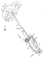
- Fig. 4 there is shown one embodiment of instrument 10 having distal end 17 of probe 16 positioned on a joint 132 of a patient's hand 136 to form holes or recesses 134 in joint 132 to effect arthrodesis in patient's joint 132.
- Instrument 10 is actuated successively and sequentially until distal end 17 of probe 16 has attained a desired depth, shape or configuration in the bone of joint 132.
- a single shock delivered by instrument 10 to bone may penetrate same by about 0.5 mm. It is typically desired that holes in bone for treating arthrodesis be 4 to 5 mm deep, and thus 3, 4, 5 and sometimes more strikes by distal tip 17 generated by instrument 10 may be required to attain the desired depth in joint 132.
- a plurality of circumferentially-located holes 134 may be formed by instrument 10 around joint 132, which causes an increased flow of blood to the various injury sites formed by holes 132, and over time the promotion of the growth of new bone therein and therearound ( i . e ., arthrodesis). Over time, the resulting new bone growth around and in joint 132 leads to joint 132 becoming substantially rigid and unmovable, which may decrease the pain sensed by the patient in joint 132.
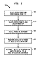
- Fig. 5 shows one embodiment of a method 100 for penetrating, resecting, or microfracturing bone to form holes or recesses therein, or for resecting or microfracturing same.
- probe 16 having distal end 17 of a desired shape or configuration is selected.
- O-ring(s) 66 having desired characteristics or properties is/are selected and mounted on proximal end 15 of probe 16.
- Probe cap 9 and/or probe receiver 14 having desired dimensions may also be selected in step 103, followed by installing the selected probe 16 in instrument 10 and attaching probe cap 9 onto distal end 11 of instrument 10 at step 105.
- distal end 17 is positioned at a selected site on the patient proximate the bone that is to be penetrated, resected or microfractured.
- instrument 10 is actuated or triggered, and a shock wave is delivered to the bone by distal end 17 of probe 16, resulting in at least the beginning of the formation of a hole or recess therein, or the resection or microfracturing thereof.
- the process of delivering of shockwaves to bone 10 by instrument 10 continues until the hole or recess attains the desired depth and/or shape or configuration, or the desired amount of resection or microfracturing has been attained.
- instrument 10 described and disclosed herein include, but are not limited to, are bone resection, anchor fixation, arthroscopy, osteotomy, arthrodesis, and the generation of microfractures in bone.
Landscapes
- Health & Medical Sciences (AREA)
- Orthopedic Medicine & Surgery (AREA)
- Life Sciences & Earth Sciences (AREA)
- Transplantation (AREA)
- Engineering & Computer Science (AREA)
- General Health & Medical Sciences (AREA)
- Biomedical Technology (AREA)
- Heart & Thoracic Surgery (AREA)
- Veterinary Medicine (AREA)
- Public Health (AREA)
- Animal Behavior & Ethology (AREA)
- Oral & Maxillofacial Surgery (AREA)
- Surgery (AREA)
- Physical Education & Sports Medicine (AREA)
- Cardiology (AREA)
- Vascular Medicine (AREA)
- Molecular Biology (AREA)
- Medical Informatics (AREA)
- Nuclear Medicine, Radiotherapy & Molecular Imaging (AREA)
- Dentistry (AREA)
- Prostheses (AREA)
- Surgical Instruments (AREA)
Abstract
Description
- Various embodiments of the invention described herein relate to the field of surgical instrumentation, and more particularly to components, devices, systems and methods associated with a pneumatic surgical instrument configured to , penetrate, resect or microfracture bone.
- Various problems can occur when forming holes or recesses in the bone of a patient, or when resecting or microfracturing bone. When engaging in such surgical procedures, physicians sometimes employ drills, chisels or other mechanical devices to form such holes or recesses, or to resect or microfracture the bone. For example, a surgical drill may be employed to form a hole or recess, which requires careful application of force to the bone by the operating physician, with uncertain results owing to non-homogeneity of the bone and other factors such as chisel, punch or drill bit placement, chisel, punch or drill bit angle, the speed of the drill, drill bit type and other variables. Such mechanical devices and other surgical tools can provide equally unreliable and inconsistent results.
- What is needed is a surgical instrument that eases the formation of holes or recesses in bone, or the resecting or microfracturing of same, that is highly repeatable, consistent and predictable in the application of force and energy.
- In one embodiment, there is provided a pneumatic surgical instrument configured to penetrate, resect or microfracture bone comprising a striker, a removable probe mountable on a distal end of the instrument, a pressure regulator operably connectable to a gas cartridge mountable on or in the instrument, and a trigger mechanism comprising a trigger, the trigger mechanism being operably connected to the pressure regulator and to the striker, wherein the probe has a distal end configured and shaped to penetrate, resect or microfracture bone, the instrument being configured to deliver at least one shock wave to the probe when the trigger is actuated by a user and a predetermined volume of gas stored at a predetermined range of pressures in the instrument is released thereby to cause the striker to move towards a distal end of the instrument and deliver the shock wave to the proximal end of the probe, the shockwave delivered by the probe to the bone being substantially repeatable by the instrument when the trigger is actuated again by the user.
- In another embodiment, there is provided a method of penetrating, resecting or microfracturing bone with a pneumatic surgical instrument configured to generate and deliver a shockwave to a probe disposed at the distal end of the instrument, the surgical instrument comprising a striker, a removable probe mountable on a distal end of the instrument, a pressure regulator operably connectable to a gas cartridge mountable on or in the instrument, and a trigger mechanism comprising a trigger, the trigger mechanism being operably connected to the pressure regulator and to the striker, wherein the probe has a distal end configured and shaped to penetrate resect or microfracture bone, the instrument being configured to deliver at least one shock wave to the probe when the trigger is actuated by a user and a predetermined volume of gas stored at a predetermined range of pressures in the instrument is released thereby to cause the striker to move towards a distal end of the instrument and deliver the shock wave to the proximal end of the probe, the shockwave delivered by the probe to the bone being substantially repeatable by the instrument when the trigger is actuated again by the user, the method comprising positioning the distal end of the probe or the impactor in contact with a patient skin or bone at a location where a recess or hole in the bone is desired to be formed, or where the bone is to be resected or microfractured, and actuating the trigger mechanism to deliver the shockwave to the probe and thence to the distal end of the probe thereby to penetrate, resect or microfracture the bone.
- Further embodiments are disclosed herein or will become apparent to those skilled in the art after having read and understood the specification and drawings hereof.
- Different aspects of the various embodiments will become apparent from the following specification, drawings and claims in which:
-
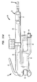
Fig. 1(a) shows a side view according to one embodiment of pneumaticsurgical instrument 10; -
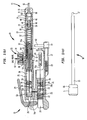
Fig. 1(b) shows a cross-sectional view according to one embodiment of pneumaticsurgical instrument 10; -
Fig. 1(c) shows a side view according to one embodiment ofprobe 16; -
Fig. 1(d) shows a top rear perspective view according to one embodiment of pneumaticsurgical instrument 10; -
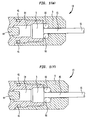
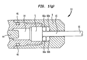
Figs. 1 (e) throughFig. 1 (g) show various embodiments ofdistal end 11 ofinstrument 10 andprobe cap 9,proximal probe terminus 5, and O-ring(s) 66. -
Figs. 2(a) through 2(h) show various embodiments ofdistal end 17 ofprobe 16; -
Figs. 3(a) and 3(b) show various characteristics of the rise times and forces of the shock waves generated byinstrument 10; -
Fig. 4 shows one embodiment ofinstrument 10 havingdistal end 17 ofprobe 16 positioned on ahand 136 of patient for the purpose of effecting arthrodesis, and -
Fig. 5 shows one embodiment of amethod 100 for penetrating and forming a hole or recess therein, or for resecting or microfracturing bone. - The drawings are not necessarily to scale. Like numbers refer to like parts or steps throughout the drawings.
- Referring now to
Figs. 1(a) ,1(b) and1(d) , there are shown side, cross-sectional and top rear perspective views according to one embodiment of pneumaticsurgical instrument 10, a commercial embodiment of which is known by the name OrthoShock™ and manufactured by OrthoWin™ of Gland, Switzerland. As shown inFigs. 1(a) ,1(b) ,1(c) and1(d) , pneumaticsurgical instrument 10 comprisesstriker 12, which in one embodiment is a piston. Removable probe orshockwave transfer device 16 is mountable ondistal end 11 ofinstrument 10.Pressure regulator 20 is operably connectable togas cartridge 40, which is mountable on or ininstrument 10. According to one embodiment,gas cartridge 40 is a medical-grade CO2 cartridge. Further according to one embodiment,trigger mechanism 30 comprises trigger ortrigger handle 24, andtrigger mechanism 30 is operably connected topressure regulator 20 andstriker 12. According to one embodiment,instrument 10 includesfront metal housing 19, reartop metal housing 25, andrear bottom housing 35. -
Fig. 1(c) shows a side view according to one embodiment ofprobe 16, where O-ring 66 is pre-mounted onproximal end 15 of the shaft projecting towardsdistal end 17 from a distal surface ofproximal probe terminus 5. According to various embodiments, and as discussed in further detail below, the thickness, mechanical properties or materials, stiffness, or other properties of O-ring 66 may be selected to provide a desired amount of displacement or other desired performance characteristics whensurgical instrument 10 is triggered or actuated. In addition,instrument 10 may be configured to receive more than one O-ring 66 betweenproximal terminus 5 andprobe cap 9. - Continuing to refer to
Figs. 1(a) through 1(d) ,probe 12 hasdistal end 17 configured and shaped to engage: (a) at least a portion of a surface of an orthopedic implant 82, 84, 88, 90, 122, 124, or 126 (see, for example,Fig. 2(c) herein), (b) a device such as a punch configured to be placed between the orthopedic implant and the distal end of the probe (not shown in the Figures), or (c) an orthopedic implant impactor 80 configured to receivedistal end 17 ofprobe 16 therein or thereon (see, for example,Figs. 3(a) through 5(b) herein). - According to some embodiments, impactor 80 is configured and shaped to engage at least a portion of the surface of an orthopedic implant.
Instrument 10 is configured to deliver at least one shock wave toprobe 16 whentrigger 24 is actuated by a user and a predetermined volume of gas stored at a predetermined range of pressures ininstrument 10 is released thereby to causestriker 12 to move towardsdistal end 11 ofinstrument 10 and deliver the shock wave toproximal end 15 ofprobe 16. - The shockwave delivered by
instrument 10 andprobe 16 is substantially repeatable byinstrument 10 whentrigger 24 is actuated again by the user for the delivery of a subsequent shockwave byinstrument 10 after the volume of gas exhausted byinstrument 10 throughgas exhaust device 33 has been replenished withininstrument 10 fromgas cartridge 40 throughgas regulator 20. - According to one embodiment, the predetermined volume of gas stored at a predetermined range of pressures is contained in a chamber disposed within
trigger mechanism 30, and is released to force the striker towardsdistal end 11 ofinstrument 10 whentrigger mechanism 30 is actuated by the user by means oftrigger handle 24 andactuator 26. Other means of triggeringtrigger mechanism 30 are contemplated, such as solenoids, mechanically depressible buttons, and so on. Moreover, the chamber containing the predetermined volume of gas stored at a predetermined range of pressures ininstrument 10 may be housed elsewhere ininstrument 10 other than as part oftrigger mechanism 30, such as, by way of example, in a chamber disposed in or attached topressure regulator 20, or in another location within or oninstrument 10. Note that in the embodiment ofinstrument 10 shown inFigs. 1(a) ,1(b) and 1(c) ,striker 12 is disposed withinlongitudinal striker sleeve 18, although other embodiments are contemplated. - Further according to various embodiments,
pneumatic instrument 10 may be configured such that the shockwave provided byprobe 16 has a rise time ranging between about 2 microseconds and about 20 microseconds, between about 4 microseconds and about 16 microseconds, or between about 6 microseconds and about 10 microseconds, more about which is said below. - Referring still to
Figs. 1(a) through 1(d) , and according to one embodiment,instrument 10 comprisesremovable probe cap 9, which is configured to receiveproximal end 15 ofprobe 16 therein or therethrough, whereprobe cap 9 is mountable ondistal end 11 ofinstrument 10, and whereproximal probe terminus 5 is located proximally withininstrument 10 behindprobe cap 9.Firing pin 44 is disposed between a distal end ofstriker 12 and a proximal end offiring pin receiver 14. The distal end ofstriker 12 is configured to engage and strike a proximal end offiring pin 44 and drive same towardsfiring pin receiver 14, which is configured to receive the distal end offiring pin 44 therein and transfer the shockwave delivered thereby toproximal probe terminus 5. - As further shown in
Fig. 1(c) , probe O-ring 66 is disposed nearproximal end 15 ofprobe 16 between an inner surface ofprobe cap 9 and a distal portion ofprobe terminus 5. In one embodiment, probe O-ring 66 comprises nitrile and has a thickness ranging between about 2 mm and about 3 mm, although other ranges of the thickness of O-ring 66 are contemplated, such as between about 1 mm and about 6 mm, between about 1.5 mm and about 5 mm, between about 2 mm and about 4 mm. In one embodiment, O-ring 66 has an inner diameter of about 2.8 mm, an outer diameter of about 7 mm, and a thickness of 2.64 mm. Other diameters and thicknesses of O-ring 66 are contemplated, however. According to one embodiment,probe 16 is displaced by about 0.5 mm wheninstrument 10 is actuated. Other amounts of the displacement ofprobe 16 wheninstrument 10 is triggered or actuated may be provided, however, such as displacement of about 0.2 mm, about 0.4 mm, about 0.6 mm, about 0.8 mm, and about 1 mm. - In conjunction with the amount of force provided by the distal end of
striker 12 to firingpin 44, firingpin receiver 14, andprobe terminus 5, the number, thickness or other properties of O-rings 66 may be configured to provide a desired amount of displacement ofprobe 16, or a desired force or energy signature, wheninstrument 10 is triggered. Further according to some embodiments, other O-rings instrument 10 may also comprise nitrile, which does not absorb CO2 gas and thus prevents the degradation or expansion of such O-rings caused by exposure to CO2 gas. - Still referring to
Fig. 1(b) , and according to one embodiment,pressure regulator 20 includes apin 31 that is configured topuncture gas cartridge 40 whenreplaceable gas cartridge 40 is mounted in or oninstrument 10.Gas cartridge 40 may be inserted or removedform instrument 10 by turning gas cartridge replacement andremoval mechanism handle 62, andcorresponding shaft end 64,rod 27, and threadedportion 29 inwardly or outwardly, as the case may be.Pressure regulator 20 directs and regulates the pressure of gas originating incartridge 40 totrigger mechanism 30, and includesspring 22, which is configured to push a valve located inpressure regulator 20 closed after a predetermined amount or volume of gas has been emitted fromcartridge 40 intopressure regulator 20 andtrigger mechanism 30. According to some embodiments,gas regulator 20 is configured to provide pressurized gas totrigger mechanism 30 at pressures ranging between about 15 bars and about 60 bars, or between about 25 bars and about 35 bars. A nominal regulated pressure of 29 bars is preferred according to one embodiment. - Continuing to refer to
Fig. 1(b) , there are shown interconnectedgas passageways gas cartridge 40,gas regulator 20, betweengas regulator 20 andtrigger mechanism 30,trigger mechanism 30, striker 12 (through central aperture 7), and around the top portion ofstriker 12. Gas travelling through such passageways is ultimately exhausted throughgas exhaust device 33 asexhaust gas 42. According to one embodiment, and as shown inFig. 1(b) ,gas exhaust device 33 comprises gasexhaust filter housing 34, a replaceable gas exhaust filter cartridge (not shown in the drawings), and gasexhaust filter valve 38.Gas exhaust device 33 is configured to trap particulate contaminants in the replaceable gas exhaust filter cartridge that may be present in gas provided bygas cartridge 40, and prevent contamination of the sterile field during a surgical procedure. - Referring to
Figs. 1(a) through 1(d) , and according to one embodiment,probe 16 comprises a metal or metal alloy such as stainless steel, and has a length ranging between about 10 cm and about 30 cm, and a diameter ranging between about 2.8 mm and about 3.4 mm. Other probe lengths and diameters are also contemplated, however. -
Figs. 1(e) through 1(f) illustrate various embodiments of certain details concerningdistal end 11 ofinstrument 10, and more particularly how the configurations and dimensions thereof may be adjusted or modified to provide different functional performance characteristics ofinstrument 10 in use. -
Fig. 1(e) shows an enlarged cross-sectional view ofdistal end 11 ofinstrument 10 that conforms with that shown inFig. 1(b) hereof. As shown inFig. 1(e) , a single O-ring 66 is disposed between a distal forward-facing surface ofproximal probe terminus 5 and an internal surface ofprobe cap 9. Wheninstrument 10 is triggered or actuated, firingpin 44 is stricken by striker 12 (not shown inFig. 1 (e) ), which then pushes firingpin receiver 14 forwardly in a distal direction against a proximal surface ofprobe terminus 5, the distal surface of which is then pushed against O-ring 66 confined against a distal internal surface ofprobe cap 9, thereby to cause displacement ofprobe 16 in the distal direction. In the embodiment shown inFig. 1(e) ,probe 16 is displaced about 0.5 mm in the distal direction when the pressure at whichinstrument 10 operates is about 29 bars, and when O-ring 66 has an inner diameter of about 2.8 mm, an outer diameter of about 7 mm, and a thickness of 2.64 mm as described above. - In
Fig. 1(f) , a single O-ring 66 is also disposed between a distal forward-facing surface ofproximal probe terminus 5 and an internal surface ofprobe cap 9, but O-ring 66 ofFig. 1 (f) is thicker than that ofFig. 1 (e) , and the space occupied by O-ring 66 inFig. 1(f) is larger and wider than that ofFig. 1(e) . Probecap 9 ofFig. 1(f) is thus configured differently from that ofFig. 1(e) so as to accommodate a larger O-ring 66, and according to the physical properties of O-ring 66 that has been selected for use may result in increased displacement ofprobe 16 than the embodiment shown inFig. 1(e) wheninstrument 10 is triggered or actuated, or may result in other changes in other functional performance characteristics ofinstrument 10 in use, as discussed above. - In
Fig. 1(g) , two O-rings proximal probe terminus 5 and an internal surface ofprobe cap 9, and the space occupied by O-rings Fig. 1(g) is also larger and wider than that ofFig. 1(e) . Probecap 9 ofFig. 1(f) is thus configured differently from that ofFig. 1(e) so as to accommodate two O-rings rings probe 16 than the embodiment shown inFig. 1(e) wheninstrument 10 is triggered or actuated, or may result in other changes in other functional performance characteristics ofinstrument 10 in use, as discussed above. - As shown in
Figs. 2(a) through 2(h) , various embodiments ofdistal end 17 ofprobe 16 may be configured to penetrate, resect or microfracture bone through the successive and sequential applications of shockwaves thereto byprobe 16 anddistal end 17 thereof to bone. In the embodiment shown inFig. 2(a) ,distal end 17 ofprobe 16 is pointed. In the embodiment shown inFig. 2(b) ,distal end 17 ofprobe 16 features harpoon-shaped protrusions. In the embodiment shown inFig. 2(c) ,distal end 17 ofprobe 16 is pointed and deflected away from a longitudinal axis associated withprobe 16. In the embodiment shown inFig. 2(d) ,distal end 17 ofprobe 16 is cross-shaped. In the embodiment shown inFig. 2(e) ,distal end 17 ofprobe 16 forms a tapered sharp point. In the embodiment shown inFig. 2(f) ,distal end 17 ofprobe 16 is U-shaped. In the embodiment shown inFig. 2(g) ,distal end 17 ofprobe 16 forms a blunted and rounded tip. In the embodiment shown inFig. 2(h) ,distal end 17 ofprobe 16 forms a tapered cross-shape. Other configurations ofdistal tip 16 are contemplated. Such as serrated tips, blade-shaped tips, and so on, that have shapes or configurations suitable for penetrating, resecting or microfracturing bone. - In conjunction with the selection of O-
ring 66 having a desired thickness, stiffness, material or other characteristics, and the selection of anremovable probe cap 9 having a suitable configuration and interior volume for housing O-ring(s) 66,instrument 10 may be configured to provide customizable amounts of displacement or other functional performance characteristics ofprobe 16 wheninstrument 10 is actuated or triggered. That is, one or more of O-ring(s) 66 andremovable probe cap 9 having certain predetermined characteristics may be selected to provide customizable amounts of displacement or other performance characteristics ofprobe 16. According to one embodiment,probe 16 is displaced by about 0.5 mm wheninstrument 10 is actuated, although other displacements ofprobe 16 may be provided byinstrument 10, such as about 0.2 mm, about 0.4 mm, about 0.6 mm, about 0.8 mm, about 1 mm, and about 1 mm. Other displacements are also contemplated. - Referring now to
Figs. 3(a) and 3(b) , there are shown various characteristics of the rise times and forces of the shock waves generated by a commercial embodiment ofinstrument 10 ofFigs. 1(a) through 1(c) known as the OrthoShock™ surgical instrument. As illustrated inFig. 3(a) , there is shown the output signal (or shockwave or impulse force) delivered according to one embodiment of the OrthoShock surgical instrument disclosed and described herein. The shockwave or impulse force output signal delivered by an OrthoShock™ surgical instrument to an orthopedic implant or device is juxtaposed with the output signals provided by a conventional orthopedic hammer. As will be seen by referring toFig. 3(a) , the rise time, or the amount of time over which the shockwave or impulse force is provided byinstrument 10 is much shorter than that provided by a conventional orthopedic hammer. In the example shown inFig. 3(a) , the total rise time is about 6 microseconds, as compared to a 50 microsecond rise time characteristic of a hammer employed for the same purpose. The steeper the curve of the output signal, the better the initial impulse. Further as shown inFig. 3(a) , the rise time of the OrthoShock™ surgical instrument is about five times greater than that of a corresponding orthopedic hammer. -
Fig. 3(b) shows a comparison of integrated output shockwave or impulse force output signals provided by one embodiment of the surgical instrument described and disclosed herein relative to those provided by a hammer, and corresponds to the results shown inFig. 3(a) . The greater the integral, especially during the first 20 microseconds in the context of delivering shockwave to an artificial hip implant insert for the purpose of ejecting same, the bigger the change in momentum, and the more energy that is usefully transferred to the orthopedic implant or device to cause its ejection from an artificial hip socket. This means that use ofsurgical instrument 10 disclosed and described herein results in particularly efficacious and easy removal, reorientation or insertion of an artificial hip implant insert with respect to an artificial hip implant socket. - Referring now to
Fig. 4 , there is shown one embodiment ofinstrument 10 havingdistal end 17 ofprobe 16 positioned on a joint 132 of a patient'shand 136 to form holes or recesses 134 in joint 132 to effect arthrodesis in patient's joint 132.Instrument 10 is actuated successively and sequentially untildistal end 17 ofprobe 16 has attained a desired depth, shape or configuration in the bone ofjoint 132. In one embodiment, a single shock delivered byinstrument 10 to bone may penetrate same by about 0.5 mm. It is typically desired that holes in bone for treating arthrodesis be 4 to 5 mm deep, and thus 3, 4, 5 and sometimes more strikes bydistal tip 17 generated byinstrument 10 may be required to attain the desired depth injoint 132. A plurality of circumferentially-locatedholes 134 may be formed byinstrument 10 aroundjoint 132, which causes an increased flow of blood to the various injury sites formed byholes 132, and over time the promotion of the growth of new bone therein and therearound (i.e., arthrodesis). Over time, the resulting new bone growth around and in joint 132 leads to joint 132 becoming substantially rigid and unmovable, which may decrease the pain sensed by the patient in joint 132. -
Fig. 5 shows one embodiment of amethod 100 for penetrating, resecting, or microfracturing bone to form holes or recesses therein, or for resecting or microfracturing same. Atstep 101, probe 16 havingdistal end 17 of a desired shape or configuration is selected. Atoptional step 103, O-ring(s) 66 having desired characteristics or properties is/are selected and mounted onproximal end 15 ofprobe 16. Probecap 9 and/or probereceiver 14 having desired dimensions may also be selected instep 103, followed by installing the selectedprobe 16 ininstrument 10 and attachingprobe cap 9 ontodistal end 11 ofinstrument 10 atstep 105. Atstep 107,distal end 17 is positioned at a selected site on the patient proximate the bone that is to be penetrated, resected or microfractured. Atstep 109,instrument 10 is actuated or triggered, and a shock wave is delivered to the bone bydistal end 17 ofprobe 16, resulting in at least the beginning of the formation of a hole or recess therein, or the resection or microfracturing thereof. The process of delivering of shockwaves tobone 10 byinstrument 10 continues until the hole or recess attains the desired depth and/or shape or configuration, or the desired amount of resection or microfracturing has been attained. - Other surgical procedures that may be carried out with
instrument 10 described and disclosed herein include, but are not limited to, are bone resection, anchor fixation, arthroscopy, osteotomy, arthrodesis, and the generation of microfractures in bone. - The above-described embodiments should be considered as examples of the present invention, rather than as limiting the scope of the invention. In addition to the foregoing embodiments of the invention, review of the detailed description and accompanying drawings will show that there are other embodiments of the present invention. Accordingly, many combinations, permutations, variations and modifications of the foregoing embodiments of the present invention not set forth explicitly herein will nevertheless fall within the scope of the present invention.
Claims (30)
- A pneumatic surgical instrument configured to penetrate, resect or microfracture bone, comprising:a striker;a removable probe mountable on a distal end of the instrument;a pressure regulator operably connectable to a gas cartridge mountable on or in the instrument, anda trigger mechanism comprising a trigger, the trigger mechanism being operably connected to the pressure regulator and to the striker;wherein the probe has a distal end configured and shaped to penetrate, resect or microfracture bone, the instrument being configured to deliver at least one shock wave to the probe when the trigger is actuated by a user and a predetermined volume of gas stored at a predetermined range of pressures in the instrument is released thereby to cause the striker to move towards a distal end of the instrument and deliver the shock wave to the proximal end of the probe, the shockwave delivered by the probe to the bone being substantially repeatable by the instrument when the trigger is actuated again by the user.
- The pneumatic surgical instrument of claim 1, wherein the distal end of the probe is one of pointed, cross-shaped, rounded, pointed and smooth, pointed and deflected away from a longitudinal axis associated with the probe, a tapered sharp point, U-shaped, blunted and rounded, a tapered cross-shape, serrated, and blade-shaped.
- The pneumatic surgical instrument of claim 1, wherein the instrument further comprises a removable probe cap configured to receive the proximal end of the probe therein or therethrough, the probe cap being mountable on the distal end of the instrument.
- The pneumatic surgical instrument of claim 1, further comprising a firing pin disposed between a distal end of the striker and the proximal end of the probe, the distal end of the striker being configured to engage and strike a proximal end of the firing pin.
- The pneumatic surgical instrument of claim 1, wherein the probe further comprises a shaft having a probe terminus disposed at the proximal end thereof.
- The pneumatic surgical instrument of claim 5, further comprising a removable probe cap configured to receive the shaft therethrough and to house proximally therefrom within the instrument at least one probe O-ring disposed against a distal surface of the proximal probe terminus, the removable probe cap being mountable on the distal end of the instrument.
- The pneumatic surgical instrument of claim 6, wherein the probe O-ring comprises nitrile and has a thickness ranging between about 1 mm and about 6 mm.
- The pneumatic surgical instrument of claim 6, wherein the probe O-ring comprises nitrile and has a thickness ranging between about 2 mm and about 4 mm.
- The pneumatic surgical instrument of claim 5, further comprising a removable probe cap configured to receive the shaft therethrough and to house proximally therefrom within the instrument a plurality of probe O-rings located near a distal surface of the proximal probe terminus, the removable probe cap being mountable on the distal end of the instrument.
- The pneumatic surgical instrument of claim 6, wherein internal dimensions of the probe cap are selected to provide a given displacement of the probe.
- The pneumatic surgical instrument of claim 1, wherein a displacement provided by the probe when the instrument is actuated or triggered is one of about 0.2 mm, about 0.4 mm, about 0.6 mm, about 0.8 mm, about 1 mm, and about 1.2 mm.
- The pneumatic surgical instrument of claim 1, wherein the pneumatic instrument is configured such that the shockwave provided by the probe has a rise time ranging between about 2 microseconds and about 20 microseconds.
- The pneumatic surgical instrument of claim 12 wherein the rise time ranges between about 4 microseconds and about 16 microseconds.
- The pneumatic surgical instrument of claim 12 wherein the rise time ranges between about 6 microseconds and about 10 microseconds.
- The pneumatic surgical instrument of claim 1, wherein the trigger mechanism further comprises a trigger chamber configured to contain the predetermined volume of gas.
- The pneumatic surgical instrument of claim 1, wherein the trigger mechanism further comprises a trigger handle and a trigger actuator operably couplable to the trigger handle.
- The pneumatic surgical instrument of claim 1, wherein the pressure regulator further comprises a pin configured to puncture the gas cartridge when the gas cartridge is mounted in or on the instrument.
- The pneumatic surgical instrument of claim 1, wherein the gas cartridge is a CO2 cartridge.
- The pneumatic surgical instrument of claim 1, wherein the gas regulator is further configured to provide pressurized gas to the trigger mechanism at pressures ranging between about 15 bars and about 60 bars.
- The pneumatic surgical instrument of claim 1, wherein the gas regulator is further configured to provide pressurized gas to the trigger mechanism at pressures ranging between about 25 bars and about 35 bars.
- The pneumatic surgical instrument of claim 1, wherein the probe further comprises stainless steel.
- The pneumatic surgical instrument of claim 1, wherein the probe has a length ranging between about 10 cm and about 30 cm.
- A method of penetrating, resecting or microfracturing bone with a pneumatic surgical instrument configured to generate and deliver a shockwave to a probe disposed at the distal end of the instrument, the surgical instrument comprising a striker, a removable probe mountable on a distal end of the instrument, a pressure regulator operably connectable to a gas cartridge mountable on or in the instrument, and a trigger mechanism comprising a trigger, the trigger mechanism being operably connected to the pressure regulator and to the striker, wherein the probe has a distal end configured and shaped to penetrate resect or microfracture bone, the instrument being configured to deliver at least one shock wave to the probe when the trigger is actuated by a user and a predetermined volume of gas stored at a predetermined range of pressures in the instrument is released thereby to cause the striker to move towards a distal end of the instrument and deliver the shock wave to the proximal end of the probe, the shockwave delivered by the probe to the bone being substantially repeatable by the instrument when the trigger is actuated again by the user, the method comprising:positioning the distal end of the probe or the impactor in contact with a patient skin or bone at a location where a recess or hole in the bone is desired to be formed, or where the bone is to be resected or microfractured, andactuating the trigger mechanism to deliver the shockwave to the probe and thence to the distal end of the probe thereby to penetrate, resect or microfracture the bone.
- The method of claim 23, further comprising sequentially delivering shockwaves to the bone until the recess or hole in the bone attains a desired depth or configuration.
- The method of claim 23, further comprising, before the instrument is actuated to penetrate, resect or microfracture the bone, selecting a probe having a distal end having a desired shape and configuration to form the recess or hole in the bone, or to resect or microfracture same.
- The method of claim 23, wherein the shock wave delivered to the probe by the instrument has a rise time ranging between about 2 microseconds and about 20 microseconds.
- The method of claim 23, wherein the rise time ranges between about 4 microseconds and about 16 microseconds.
- The method of claim 24, wherein the rise time ranges between about 6 microseconds and about 10 microseconds.
- The method of claim 24, further comprising, before the instrument is actuated to penetrate, resect or microfracture the bone, selecting at least one of an O-ring, a probe cap and a probe receiver configured to provide a desired displacement of the distal end of the probe into the bone with each delivery of a shockwave to the bone by the instrument.
- The method of claim 23, further comprising attaching or anchoring one or more orthopedic implants in the hole or recess formed by the instrument in the bone.
Applications Claiming Priority (5)
| Application Number | Priority Date | Filing Date | Title |
|---|---|---|---|
| US201161449958P | 2011-03-07 | 2011-03-07 | |
| US201161449934P | 2011-03-07 | 2011-03-07 | |
| US201161449942P | 2011-03-07 | 2011-03-07 | |
| US201161449948P | 2011-03-07 | 2011-03-07 | |
| US201261596193P | 2012-02-07 | 2012-02-07 |
Publications (2)
| Publication Number | Publication Date |
|---|---|
| EP2502581A1 true EP2502581A1 (en) | 2012-09-26 |
| EP2502581B1 EP2502581B1 (en) | 2016-01-13 |
Family
ID=46683073
Family Applications (2)
| Application Number | Title | Priority Date | Filing Date |
|---|---|---|---|
| EP12356004.7A Active EP2502580B1 (en) | 2011-03-07 | 2012-03-07 | Pneumatic surgical instrument |
| EP12356005.4A Active EP2502581B1 (en) | 2011-03-07 | 2012-03-07 | Pneumatic surgical instrument |
Family Applications Before (1)
| Application Number | Title | Priority Date | Filing Date |
|---|---|---|---|
| EP12356004.7A Active EP2502580B1 (en) | 2011-03-07 | 2012-03-07 | Pneumatic surgical instrument |
Country Status (2)
| Country | Link |
|---|---|
| US (3) | US8936603B2 (en) |
| EP (2) | EP2502580B1 (en) |
Cited By (3)
| Publication number | Priority date | Publication date | Assignee | Title |
|---|---|---|---|---|
| EP2662035A1 (en) * | 2012-02-07 | 2013-11-13 | OrthoWin SA | Pneumatic surgical instrument for implanting orthopedic implants in bone |
| US9999518B2 (en) | 2011-03-07 | 2018-06-19 | Biomet Global Supply Chain Center | Pneumatic surgical instrument and corresponding methods for implanting, extracting and reorienting orthopedic implants |
| WO2019068088A3 (en) * | 2017-09-29 | 2019-05-09 | Smith & Nephew, Inc. | Surgical punch tool for robotically assisted bone preparation for positioning of a cutting block |
Families Citing this family (48)
| Publication number | Priority date | Publication date | Assignee | Title |
|---|---|---|---|---|
| EP3162314B1 (en) | 2010-12-29 | 2019-02-27 | DePuy Synthes Products, Inc. | Electric motor driven tool for orthopedic impacting |
| US8695726B2 (en) | 2010-12-29 | 2014-04-15 | Medical Enterprises LLC | Electric motor driven tool for orthopedic impacting |
| US10149711B2 (en) * | 2012-03-30 | 2018-12-11 | Depuy Mitek, Llc | Surgical impact tool |
| US9987067B2 (en) * | 2012-07-11 | 2018-06-05 | Zimmer, Inc. | Bone fixation tool |
| US9005213B2 (en) | 2012-11-16 | 2015-04-14 | DePuy Synthes Products, Inc. | Controlled force surgical implant impaction instrument |
| US10592062B2 (en) * | 2014-01-06 | 2020-03-17 | Samsung Electronics Co., Ltd. | Control apparatus |
| CN103743637B (en) * | 2014-01-23 | 2016-02-03 | 中国人民解放军总医院 | A kind of impact head and apply its ram |
| US10456264B2 (en) | 2014-01-24 | 2019-10-29 | Tornier, Inc. | Humeral implant anchor system |
| US12023253B2 (en) | 2014-01-24 | 2024-07-02 | Howmedica Osteonics Corp. | Humeral implant anchor system |
| EP3125797B1 (en) | 2014-04-03 | 2019-05-22 | Zimmer, Inc. | Orthopedic tool for bone fixation |
| WO2015179646A1 (en) | 2014-05-21 | 2015-11-26 | The Uab Research Foundation | Hinged microfracture awls |
| CA2973470C (en) | 2015-01-09 | 2023-03-28 | Corex, Llc | Electric motor driven tool for orthopedic impacting |
| CN104887281A (en) * | 2015-06-23 | 2015-09-09 | 苏州市瑞晟医疗器械有限公司 | Wave source device of orthopedic therapy machine |
| US11109802B2 (en) | 2016-01-11 | 2021-09-07 | Kambiz Behzadi | Invasive sense measurement in prosthesis installation and bone preparation |
| US10849766B2 (en) | 2016-01-11 | 2020-12-01 | Kambiz Behzadi | Implant evaluation in prosthesis installation |
| US11751807B2 (en) | 2016-01-11 | 2023-09-12 | Kambiz Behzadi | Invasive sense measurement in prosthesis installation and bone preparation |
| US11241248B2 (en) | 2016-01-11 | 2022-02-08 | Kambiz Behzadi | Bone preparation apparatus and method |
| US11458028B2 (en) | 2016-01-11 | 2022-10-04 | Kambiz Behzadi | Prosthesis installation and assembly |
| US10251663B2 (en) | 2016-01-11 | 2019-04-09 | Kambiz Behzadi | Bone preparation apparatus and method |
| US11026809B2 (en) | 2016-01-11 | 2021-06-08 | Kambiz Behzadi | Prosthesis installation and assembly |
| US10441244B2 (en) | 2016-01-11 | 2019-10-15 | Kambiz Behzadi | Invasive sense measurement in prosthesis installation |
| US11298102B2 (en) | 2016-01-11 | 2022-04-12 | Kambiz Behzadi | Quantitative assessment of prosthesis press-fit fixation |
| US20170196707A1 (en) | 2016-01-11 | 2017-07-13 | Kambiz Behzadi | Surgical impaction centering apparatus and method |
| US11331069B2 (en) | 2016-01-11 | 2022-05-17 | Kambiz Behzadi | Invasive sense measurement in prosthesis installation |
| US11291426B2 (en) | 2016-01-11 | 2022-04-05 | Kambiz Behzadi | Quantitative assessment of implant bone preparation |
| US11375975B2 (en) | 2016-01-11 | 2022-07-05 | Kambiz Behzadi | Quantitative assessment of implant installation |
| US11234840B2 (en) | 2016-01-11 | 2022-02-01 | Kambiz Behzadi | Bone preparation apparatus and method |
| US11399946B2 (en) | 2016-01-11 | 2022-08-02 | Kambiz Behzadi | Prosthesis installation and assembly |
| US12193951B2 (en) | 2016-01-11 | 2025-01-14 | Kambiz Behzadi | Quantitative assessment of prosthesis press-fit fixation |
| US11534314B2 (en) | 2016-01-11 | 2022-12-27 | Kambiz Behzadi | Quantitative assessment of prosthesis press-fit fixation |
| US10463499B2 (en) | 2016-03-25 | 2019-11-05 | Tornier, Inc. | Stemless shoulder implant with fixation components |
| US11129724B2 (en) | 2016-07-28 | 2021-09-28 | Howmedica Osteonics Corp. | Stemless prosthesis anchor component |
| WO2019060780A2 (en) | 2017-09-25 | 2019-03-28 | Tornier, Inc. | Patient specific stemless prosthesis anchor components |
| US11399948B2 (en) | 2017-12-11 | 2022-08-02 | Howmedica Osteonics Corp. | Stemless prosthesis anchor components and kits |
| EP3723644B1 (en) | 2017-12-15 | 2026-05-06 | DePuy Synthes Products, Inc. | Orthopedic adapter for an electric impacting tool |
| WO2020072452A1 (en) | 2018-10-02 | 2020-04-09 | Tornier, Inc. | Shoulder prosthesis components and assemblies |
| US11969336B2 (en) | 2018-10-08 | 2024-04-30 | Kambiz Behzadi | Connective tissue grafting |
| US11324530B2 (en) * | 2019-04-22 | 2022-05-10 | Medos International Sarl | Bone and tissue resection devices and methods |
| US11350948B2 (en) | 2019-04-22 | 2022-06-07 | Medos International Sarl | Bone and tissue resection devices and methods |
| US11413056B2 (en) | 2019-04-22 | 2022-08-16 | Medos International Sarl | Bone and tissue resection devices and methods |
| US11389178B2 (en) | 2019-04-22 | 2022-07-19 | Medos International Sarl | Bone and tissue resection devices and methods |
| US12370051B2 (en) * | 2019-10-01 | 2025-07-29 | Howmedica Osteonics Corp. | Shoulder prosthesis components and assemblies |
| US12186003B2 (en) * | 2020-12-15 | 2025-01-07 | Moxie Medical, LLC | Bi-directional pneumatic impactor for orthopedic devices |
| US12329585B2 (en) * | 2021-01-26 | 2025-06-17 | Fidelis Partners, LLC | Rotary tool with reduced recoil for orthopedic surgery |
| US11877780B2 (en) * | 2021-01-26 | 2024-01-23 | Fidelis Partners, LLC | Rotary impactor for orthopedic surgery |
| US12064356B2 (en) * | 2021-08-19 | 2024-08-20 | Howmedica Osteonics Corp. | Multi-size acetabular impactor |
| AU2023231283A1 (en) * | 2022-03-10 | 2024-09-19 | Pro-Dex, Inc. | Surgical impactor |
| WO2025106740A1 (en) * | 2023-11-15 | 2025-05-22 | Orthoiq, Llc | Orthopedic surgery systems and devices for impacting implements in bones |
Citations (2)
| Publication number | Priority date | Publication date | Assignee | Title |
|---|---|---|---|---|
| US3465835A (en) * | 1967-12-05 | 1969-09-09 | Lawrence R Krivit | Pin-driving device |
| US20060069395A1 (en) * | 2003-02-14 | 2006-03-30 | Alain Lebet | Single-blow shockwave generation device |
Family Cites Families (47)
| Publication number | Priority date | Publication date | Assignee | Title |
|---|---|---|---|---|
| US2275102A (en) | 1940-08-24 | 1942-03-03 | Flannery Bolt Co | Telltale hole opener for staybolts |
| US3250334A (en) | 1963-08-13 | 1966-05-10 | Sussman Ernst | Impact tools |
| US4016873A (en) | 1976-04-01 | 1977-04-12 | Anderson Otis F | Pneumatic impacter |
| DE2618596C2 (en) | 1976-04-28 | 1984-05-17 | Robert Bosch Gmbh, 7000 Stuttgart | Tool holder |
| US4298074A (en) * | 1976-08-09 | 1981-11-03 | American Safety Equipment Corporation | Surgical device using impulse motor |
| US4150656A (en) * | 1977-02-04 | 1979-04-24 | Bangor Punta Operations, Inc. | Gas fired gun with gas cartridge puncture device |
| US4135517A (en) * | 1977-07-21 | 1979-01-23 | Minnesota Mining And Manufacturing Company | Femoral prosthesis trial fitting device |
| DE2944710A1 (en) | 1979-11-06 | 1981-05-07 | Christos Dr. Dimakos | DEVICE FOR REMOVING A BONE CEMENT TUBE IN A REIMPLANTATION OF AN ARTIFICIAL THIGH NECK |
| US4357940A (en) * | 1979-12-13 | 1982-11-09 | Detroit Neurosurgical Foundation | Tissue pneumatic separator structure |
| US4399813A (en) * | 1981-01-22 | 1983-08-23 | Barber Forest C | Apparatus and method for removing a prosthesis embedded in skeletal bone |
| US4462395A (en) | 1983-03-02 | 1984-07-31 | Johnson Lanny L | Arthroscopic ligamentous and capsular fixation system |
| US4716890A (en) | 1986-01-29 | 1988-01-05 | Bichel Ronald A | Chiropractic thruster |
| ES2030897T3 (en) | 1987-11-18 | 1992-11-16 | Ferton Holding | DEVICE TO ACT ON AN OBJECT THROUGH ULTRASONIC VIBRATIONS. |
| EP0354943B1 (en) | 1988-01-21 | 1993-12-29 | Aesculap Ag | Percussion tool for surgical instruments |
| US5057112A (en) | 1990-01-04 | 1991-10-15 | Intermedics Orthopedics, Inc. | Pneumatically powered orthopedic broach |
| US5171313A (en) | 1991-05-08 | 1992-12-15 | Othy, Inc. | Tool driver |
| US5169399A (en) * | 1991-10-17 | 1992-12-08 | Boehringer Mannheim Corporation | Acetabular cup impactor |
| US5352230A (en) * | 1992-02-19 | 1994-10-04 | Biomet, Inc. | Pneumatic impulse tool |
| US5536272A (en) | 1993-03-26 | 1996-07-16 | Orthosonics Ltd. | Method for removal of osteal prostheses |
| USD362503S (en) | 1994-01-26 | 1995-09-19 | Zimmer, Inc. | Offset adaptor for an orthopaedic driver instrument |
| WO1995022934A1 (en) | 1994-02-23 | 1995-08-31 | Synvasive Technology, Inc. | Surgical chisel tool and method |
| US5449363A (en) | 1994-05-06 | 1995-09-12 | Browne Medical Systems, Inc. | Endoscopic lithotripsy system |
| US5613483A (en) | 1995-11-09 | 1997-03-25 | Lukas; Michael A. | Gas powered gun |
| US5906623A (en) | 1995-12-11 | 1999-05-25 | Boston Scientific Corporation | Lithotripsy system |
| DE19624446C1 (en) * | 1996-06-19 | 1998-03-26 | Ferton Holding | Surgical instrument for mechanical removal of bone cement, and method for generating shock waves |
| TR199601026A1 (en) | 1996-12-18 | 1998-07-21 | PCK ELEKTRONİK SAN. ve TİC. LTD. ŞTİ. | Stone breaking device with vibration inside the body. |
| US5980528A (en) | 1997-05-01 | 1999-11-09 | Salys; Scott Casimer | Hand operable pneumatically driver controllable pulse medical actuator |
| DE19813328A1 (en) * | 1998-03-26 | 1999-09-30 | Ceramtec Ag | Device for handling ball heads of joint prostheses |
| US6152930A (en) | 1998-10-28 | 2000-11-28 | Depuy Orthopaedics, Inc. | Acetabular cup extraction system |
| DE10029580C1 (en) | 2000-06-15 | 2002-01-10 | Ferton Holding Sa | Device for removing body stones with an intracorporeal lithotripter |
| US6622802B2 (en) | 2001-03-29 | 2003-09-23 | Intel Corporation | Fastener installation tool and methods of use |
| US6723102B2 (en) | 2001-06-14 | 2004-04-20 | Alexandria Research Technologies, Llc | Apparatus and method for minimally invasive total joint replacement |
| US6920960B2 (en) | 2001-06-28 | 2005-07-26 | Medtronic, Inc. | Lubrication cartridge for a pneumatically powered surgical instrument |
| GB0122295D0 (en) * | 2001-09-14 | 2001-11-07 | Benoist Girard Sas | Resilient thimble for ball head of prosthetic joint |
| US20030229357A1 (en) * | 2002-06-10 | 2003-12-11 | Donald Dye | Femoral head holder and impaction instrument and method of use |
| US6960214B2 (en) * | 2002-10-15 | 2005-11-01 | Zimmer Austin, Inc. | Method for performing automated microfracture |
| DE10327858A1 (en) | 2003-06-18 | 2005-01-05 | Robert Bosch Gmbh | Windscreen wiper device, in particular for a motor vehicle |
| EP1514518A1 (en) | 2003-09-11 | 2005-03-16 | SDGI Holdings, Inc. | Impulsive percussion instruments for endplate preparation |
| US7485149B1 (en) | 2003-10-06 | 2009-02-03 | Biomet Manufacturing Corporation | Method and apparatus for use of a non-invasive expandable implant |
| US7326217B2 (en) | 2003-11-28 | 2008-02-05 | Bubb Stephen K | Orthopedic and dental implant system and method |
| US20060100553A1 (en) | 2004-10-25 | 2006-05-11 | Lodin David W | Heart valve decalcification method and apparatus |
| DK2231220T3 (en) | 2007-12-19 | 2014-01-20 | Cook Medical Technologies Llc | HANDLING FOR WATER BREAD PUMP VACUUM |
| FR2925841B1 (en) | 2007-12-26 | 2011-08-05 | Ceram I | HIP PROSTHESIS, IN PARTICULAR FOR PROXIMAL FRACTURE OR FEMUR AND ANCILLARY POSE |
| US8926625B2 (en) | 2009-03-27 | 2015-01-06 | Alain Lebet | Surgical device |
| EP2434970B1 (en) * | 2009-05-26 | 2016-11-30 | Zimmer, Inc. | Handheld tool for driving a bone pin into a fractured bone |
| US8936603B2 (en) | 2011-03-07 | 2015-01-20 | Frederic Mani | Pneumatic surgical instrument and corresponding methods for penetrating, resecting and microfracturing bone |
| US8968326B2 (en) | 2012-02-07 | 2015-03-03 | Frederic Mani | Pneumatic surgical instrument and corresponding methods for implanting orthopedic implants in bone |
-
2012
- 2012-03-06 US US13/413,455 patent/US8936603B2/en active Active
- 2012-03-06 US US13/413,551 patent/US8936604B2/en active Active
- 2012-03-07 EP EP12356004.7A patent/EP2502580B1/en active Active
- 2012-03-07 EP EP12356005.4A patent/EP2502581B1/en active Active
-
2015
- 2015-01-12 US US14/595,160 patent/US9999518B2/en active Active
Patent Citations (2)
| Publication number | Priority date | Publication date | Assignee | Title |
|---|---|---|---|---|
| US3465835A (en) * | 1967-12-05 | 1969-09-09 | Lawrence R Krivit | Pin-driving device |
| US20060069395A1 (en) * | 2003-02-14 | 2006-03-30 | Alain Lebet | Single-blow shockwave generation device |
Non-Patent Citations (1)
| Title |
|---|
| MANI, FREDERIC: "OrthoShock Pneumatic Orthopedic Ancillary - Instruction Manual (Our IFU for Europe)", 31 December 2010 (2010-12-31), pages 1 - 28, XP002681156, Retrieved from the Internet <URL:http://www.orthowin.com/media/files/IFU%20OrthoShock%20EUROPE.pdf> [retrieved on 20120801] * |
Cited By (4)
| Publication number | Priority date | Publication date | Assignee | Title |
|---|---|---|---|---|
| US9999518B2 (en) | 2011-03-07 | 2018-06-19 | Biomet Global Supply Chain Center | Pneumatic surgical instrument and corresponding methods for implanting, extracting and reorienting orthopedic implants |
| EP2662035A1 (en) * | 2012-02-07 | 2013-11-13 | OrthoWin SA | Pneumatic surgical instrument for implanting orthopedic implants in bone |
| WO2019068088A3 (en) * | 2017-09-29 | 2019-05-09 | Smith & Nephew, Inc. | Surgical punch tool for robotically assisted bone preparation for positioning of a cutting block |
| US11266421B2 (en) | 2017-09-29 | 2022-03-08 | Smith & Nephew, Inc. | Robotically assisted bone preparation for positioning of cutting block |
Also Published As
| Publication number | Publication date |
|---|---|
| EP2502580B1 (en) | 2016-01-13 |
| US9999518B2 (en) | 2018-06-19 |
| US8936603B2 (en) | 2015-01-20 |
| US8936604B2 (en) | 2015-01-20 |
| US20150127013A1 (en) | 2015-05-07 |
| US20120232562A1 (en) | 2012-09-13 |
| EP2502581B1 (en) | 2016-01-13 |
| EP2502580A1 (en) | 2012-09-26 |
| US20120232556A1 (en) | 2012-09-13 |
Similar Documents
| Publication | Publication Date | Title |
|---|---|---|
| US8936603B2 (en) | Pneumatic surgical instrument and corresponding methods for penetrating, resecting and microfracturing bone | |
| US8968326B2 (en) | Pneumatic surgical instrument and corresponding methods for implanting orthopedic implants in bone | |
| US12161347B2 (en) | Microfracture apparatuses and methods | |
| CN104519814B (en) | Motor-driven tools for orthopedic impact | |
| AU2007226568B2 (en) | Microfracture pick | |
| US20180110531A1 (en) | System and method for harvesting bone graft | |
| US20140336656A1 (en) | Microfracture pick | |
| JP6571334B2 (en) | Micro fracture pick | |
| JP2019063582A (en) | Microfracture pick | |
| US10524816B2 (en) | Tunnel tool for soft tissue | |
| KR101152883B1 (en) | An operation device for herniation of intervertebral discs | |
| WO2024185607A1 (en) | Surgical device |
Legal Events
| Date | Code | Title | Description |
|---|---|---|---|
| PUAI | Public reference made under article 153(3) epc to a published international application that has entered the european phase |
Free format text: ORIGINAL CODE: 0009012 |
|
| AK | Designated contracting states |
Kind code of ref document: A1 Designated state(s): AL AT BE BG CH CY CZ DE DK EE ES FI FR GB GR HR HU IE IS IT LI LT LU LV MC MK MT NL NO PL PT RO RS SE SI SK SM TR |
|
| AX | Request for extension of the european patent |
Extension state: BA ME |
|
| 17P | Request for examination filed |
Effective date: 20130322 |
|
| GRAP | Despatch of communication of intention to grant a patent |
Free format text: ORIGINAL CODE: EPIDOSNIGR1 |
|
| RIC1 | Information provided on ipc code assigned before grant |
Ipc: A61B 17/16 20060101AFI20150609BHEP Ipc: A61F 2/34 20060101ALN20150609BHEP Ipc: A61F 2/36 20060101ALN20150609BHEP Ipc: A61B 17/92 20060101ALI20150609BHEP Ipc: A61F 2/46 20060101ALI20150609BHEP |
|
| INTG | Intention to grant announced |
Effective date: 20150708 |
|
| GRAS | Grant fee paid |
Free format text: ORIGINAL CODE: EPIDOSNIGR3 |
|
| GRAA | (expected) grant |
Free format text: ORIGINAL CODE: 0009210 |
|
| AK | Designated contracting states |
Kind code of ref document: B1 Designated state(s): AL AT BE BG CH CY CZ DE DK EE ES FI FR GB GR HR HU IE IS IT LI LT LU LV MC MK MT NL NO PL PT RO RS SE SI SK SM TR |
|
| REG | Reference to a national code |
Ref country code: GB Ref legal event code: FG4D |
|
| REG | Reference to a national code |
Ref country code: CH Ref legal event code: EP |
|
| REG | Reference to a national code |
Ref country code: IE Ref legal event code: FG4D |
|
| REG | Reference to a national code |
Ref country code: AT Ref legal event code: REF Ref document number: 769962 Country of ref document: AT Kind code of ref document: T Effective date: 20160215 |
|
| REG | Reference to a national code |
Ref country code: DE Ref legal event code: R096 Ref document number: 602012013855 Country of ref document: DE |
|
| REG | Reference to a national code |
Ref country code: CH Ref legal event code: NV Representative=s name: MICHELI AND CIE SA, CH |
|
| REG | Reference to a national code |
Ref country code: LT Ref legal event code: MG4D |
|
| REG | Reference to a national code |
Ref country code: NL Ref legal event code: MP Effective date: 20160113 |
|
| REG | Reference to a national code |
Ref country code: AT Ref legal event code: MK05 Ref document number: 769962 Country of ref document: AT Kind code of ref document: T Effective date: 20160113 |
|
| PG25 | Lapsed in a contracting state [announced via postgrant information from national office to epo] |
Ref country code: NL Free format text: LAPSE BECAUSE OF FAILURE TO SUBMIT A TRANSLATION OF THE DESCRIPTION OR TO PAY THE FEE WITHIN THE PRESCRIBED TIME-LIMIT Effective date: 20160113 |
|
| PG25 | Lapsed in a contracting state [announced via postgrant information from national office to epo] |
Ref country code: HR Free format text: LAPSE BECAUSE OF FAILURE TO SUBMIT A TRANSLATION OF THE DESCRIPTION OR TO PAY THE FEE WITHIN THE PRESCRIBED TIME-LIMIT Effective date: 20160113 Ref country code: ES Free format text: LAPSE BECAUSE OF FAILURE TO SUBMIT A TRANSLATION OF THE DESCRIPTION OR TO PAY THE FEE WITHIN THE PRESCRIBED TIME-LIMIT Effective date: 20160113 Ref country code: FI Free format text: LAPSE BECAUSE OF FAILURE TO SUBMIT A TRANSLATION OF THE DESCRIPTION OR TO PAY THE FEE WITHIN THE PRESCRIBED TIME-LIMIT Effective date: 20160113 Ref country code: NO Free format text: LAPSE BECAUSE OF FAILURE TO SUBMIT A TRANSLATION OF THE DESCRIPTION OR TO PAY THE FEE WITHIN THE PRESCRIBED TIME-LIMIT Effective date: 20160413 Ref country code: GR Free format text: LAPSE BECAUSE OF FAILURE TO SUBMIT A TRANSLATION OF THE DESCRIPTION OR TO PAY THE FEE WITHIN THE PRESCRIBED TIME-LIMIT Effective date: 20160414 Ref country code: IT Free format text: LAPSE BECAUSE OF FAILURE TO SUBMIT A TRANSLATION OF THE DESCRIPTION OR TO PAY THE FEE WITHIN THE PRESCRIBED TIME-LIMIT Effective date: 20160113 |
|
| PG25 | Lapsed in a contracting state [announced via postgrant information from national office to epo] |
Ref country code: LV Free format text: LAPSE BECAUSE OF FAILURE TO SUBMIT A TRANSLATION OF THE DESCRIPTION OR TO PAY THE FEE WITHIN THE PRESCRIBED TIME-LIMIT Effective date: 20160113 Ref country code: AT Free format text: LAPSE BECAUSE OF FAILURE TO SUBMIT A TRANSLATION OF THE DESCRIPTION OR TO PAY THE FEE WITHIN THE PRESCRIBED TIME-LIMIT Effective date: 20160113 Ref country code: RS Free format text: LAPSE BECAUSE OF FAILURE TO SUBMIT A TRANSLATION OF THE DESCRIPTION OR TO PAY THE FEE WITHIN THE PRESCRIBED TIME-LIMIT Effective date: 20160113 Ref country code: BE Free format text: LAPSE BECAUSE OF NON-PAYMENT OF DUE FEES Effective date: 20160331 Ref country code: PT Free format text: LAPSE BECAUSE OF FAILURE TO SUBMIT A TRANSLATION OF THE DESCRIPTION OR TO PAY THE FEE WITHIN THE PRESCRIBED TIME-LIMIT Effective date: 20160513 Ref country code: SE Free format text: LAPSE BECAUSE OF FAILURE TO SUBMIT A TRANSLATION OF THE DESCRIPTION OR TO PAY THE FEE WITHIN THE PRESCRIBED TIME-LIMIT Effective date: 20160113 Ref country code: IS Free format text: LAPSE BECAUSE OF FAILURE TO SUBMIT A TRANSLATION OF THE DESCRIPTION OR TO PAY THE FEE WITHIN THE PRESCRIBED TIME-LIMIT Effective date: 20160513 Ref country code: PL Free format text: LAPSE BECAUSE OF FAILURE TO SUBMIT A TRANSLATION OF THE DESCRIPTION OR TO PAY THE FEE WITHIN THE PRESCRIBED TIME-LIMIT Effective date: 20160113 Ref country code: LT Free format text: LAPSE BECAUSE OF FAILURE TO SUBMIT A TRANSLATION OF THE DESCRIPTION OR TO PAY THE FEE WITHIN THE PRESCRIBED TIME-LIMIT Effective date: 20160113 |
|
| REG | Reference to a national code |
Ref country code: DE Ref legal event code: R097 Ref document number: 602012013855 Country of ref document: DE |
|
| PG25 | Lapsed in a contracting state [announced via postgrant information from national office to epo] |
Ref country code: LU Free format text: LAPSE BECAUSE OF FAILURE TO SUBMIT A TRANSLATION OF THE DESCRIPTION OR TO PAY THE FEE WITHIN THE PRESCRIBED TIME-LIMIT Effective date: 20160307 Ref country code: EE Free format text: LAPSE BECAUSE OF FAILURE TO SUBMIT A TRANSLATION OF THE DESCRIPTION OR TO PAY THE FEE WITHIN THE PRESCRIBED TIME-LIMIT Effective date: 20160113 Ref country code: MC Free format text: LAPSE BECAUSE OF FAILURE TO SUBMIT A TRANSLATION OF THE DESCRIPTION OR TO PAY THE FEE WITHIN THE PRESCRIBED TIME-LIMIT Effective date: 20160113 Ref country code: DK Free format text: LAPSE BECAUSE OF FAILURE TO SUBMIT A TRANSLATION OF THE DESCRIPTION OR TO PAY THE FEE WITHIN THE PRESCRIBED TIME-LIMIT Effective date: 20160113 |
|
| PLBE | No opposition filed within time limit |
Free format text: ORIGINAL CODE: 0009261 |
|
| STAA | Information on the status of an ep patent application or granted ep patent |
Free format text: STATUS: NO OPPOSITION FILED WITHIN TIME LIMIT |
|
| PG25 | Lapsed in a contracting state [announced via postgrant information from national office to epo] |
Ref country code: RO Free format text: LAPSE BECAUSE OF FAILURE TO SUBMIT A TRANSLATION OF THE DESCRIPTION OR TO PAY THE FEE WITHIN THE PRESCRIBED TIME-LIMIT Effective date: 20160113 Ref country code: CZ Free format text: LAPSE BECAUSE OF FAILURE TO SUBMIT A TRANSLATION OF THE DESCRIPTION OR TO PAY THE FEE WITHIN THE PRESCRIBED TIME-LIMIT Effective date: 20160113 Ref country code: SK Free format text: LAPSE BECAUSE OF FAILURE TO SUBMIT A TRANSLATION OF THE DESCRIPTION OR TO PAY THE FEE WITHIN THE PRESCRIBED TIME-LIMIT Effective date: 20160113 Ref country code: SM Free format text: LAPSE BECAUSE OF FAILURE TO SUBMIT A TRANSLATION OF THE DESCRIPTION OR TO PAY THE FEE WITHIN THE PRESCRIBED TIME-LIMIT Effective date: 20160113 |
|
| 26N | No opposition filed |
Effective date: 20161014 |
|
| REG | Reference to a national code |
Ref country code: IE Ref legal event code: MM4A |
|
| PG25 | Lapsed in a contracting state [announced via postgrant information from national office to epo] |
Ref country code: BE Free format text: LAPSE BECAUSE OF FAILURE TO SUBMIT A TRANSLATION OF THE DESCRIPTION OR TO PAY THE FEE WITHIN THE PRESCRIBED TIME-LIMIT Effective date: 20160113 |
|
| REG | Reference to a national code |
Ref country code: FR Ref legal event code: ST Effective date: 20161130 |
|
| PG25 | Lapsed in a contracting state [announced via postgrant information from national office to epo] |
Ref country code: IE Free format text: LAPSE BECAUSE OF NON-PAYMENT OF DUE FEES Effective date: 20160307 Ref country code: FR Free format text: LAPSE BECAUSE OF NON-PAYMENT OF DUE FEES Effective date: 20160331 |
|
| PG25 | Lapsed in a contracting state [announced via postgrant information from national office to epo] |
Ref country code: SI Free format text: LAPSE BECAUSE OF FAILURE TO SUBMIT A TRANSLATION OF THE DESCRIPTION OR TO PAY THE FEE WITHIN THE PRESCRIBED TIME-LIMIT Effective date: 20160113 Ref country code: BG Free format text: LAPSE BECAUSE OF FAILURE TO SUBMIT A TRANSLATION OF THE DESCRIPTION OR TO PAY THE FEE WITHIN THE PRESCRIBED TIME-LIMIT Effective date: 20160413 |
|
| PG25 | Lapsed in a contracting state [announced via postgrant information from national office to epo] |
Ref country code: MT Free format text: LAPSE BECAUSE OF FAILURE TO SUBMIT A TRANSLATION OF THE DESCRIPTION OR TO PAY THE FEE WITHIN THE PRESCRIBED TIME-LIMIT Effective date: 20160113 |
|
| PG25 | Lapsed in a contracting state [announced via postgrant information from national office to epo] |
Ref country code: CY Free format text: LAPSE BECAUSE OF FAILURE TO SUBMIT A TRANSLATION OF THE DESCRIPTION OR TO PAY THE FEE WITHIN THE PRESCRIBED TIME-LIMIT Effective date: 20160113 Ref country code: HU Free format text: LAPSE BECAUSE OF FAILURE TO SUBMIT A TRANSLATION OF THE DESCRIPTION OR TO PAY THE FEE WITHIN THE PRESCRIBED TIME-LIMIT; INVALID AB INITIO Effective date: 20120307 |
|
| PG25 | Lapsed in a contracting state [announced via postgrant information from national office to epo] |
Ref country code: MK Free format text: LAPSE BECAUSE OF FAILURE TO SUBMIT A TRANSLATION OF THE DESCRIPTION OR TO PAY THE FEE WITHIN THE PRESCRIBED TIME-LIMIT Effective date: 20160113 Ref country code: TR Free format text: LAPSE BECAUSE OF FAILURE TO SUBMIT A TRANSLATION OF THE DESCRIPTION OR TO PAY THE FEE WITHIN THE PRESCRIBED TIME-LIMIT Effective date: 20160113 Ref country code: MT Free format text: LAPSE BECAUSE OF FAILURE TO SUBMIT A TRANSLATION OF THE DESCRIPTION OR TO PAY THE FEE WITHIN THE PRESCRIBED TIME-LIMIT Effective date: 20160331 |
|
| PG25 | Lapsed in a contracting state [announced via postgrant information from national office to epo] |
Ref country code: AL Free format text: LAPSE BECAUSE OF FAILURE TO SUBMIT A TRANSLATION OF THE DESCRIPTION OR TO PAY THE FEE WITHIN THE PRESCRIBED TIME-LIMIT Effective date: 20160113 |
|
| REG | Reference to a national code |
Ref country code: DE Ref legal event code: R082 Ref document number: 602012013855 Country of ref document: DE Representative=s name: VENNER SHIPLEY GERMANY LLP, DE Ref country code: DE Ref legal event code: R082 Ref document number: 602012013855 Country of ref document: DE Representative=s name: VENNER SHIPLEY LLP, DE |
|
| PGFP | Annual fee paid to national office [announced via postgrant information from national office to epo] |
Ref country code: DE Payment date: 20250228 Year of fee payment: 14 |
|
| PGFP | Annual fee paid to national office [announced via postgrant information from national office to epo] |
Ref country code: GB Payment date: 20250221 Year of fee payment: 14 |
|
| PGFP | Annual fee paid to national office [announced via postgrant information from national office to epo] |
Ref country code: CH Payment date: 20250401 Year of fee payment: 14 |