EP2502428B1 - Hearing assistance system and method - Google Patents
Hearing assistance system and method Download PDFInfo
- Publication number
- EP2502428B1 EP2502428B1 EP09751947.4A EP09751947A EP2502428B1 EP 2502428 B1 EP2502428 B1 EP 2502428B1 EP 09751947 A EP09751947 A EP 09751947A EP 2502428 B1 EP2502428 B1 EP 2502428B1
- Authority
- EP
- European Patent Office
- Prior art keywords
- audio signals
- audio
- digital
- unit
- transmission unit
- Prior art date
- Legal status (The legal status is an assumption and is not a legal conclusion. Google has not performed a legal analysis and makes no representation as to the accuracy of the status listed.)
- Not-in-force
Links
Images
Classifications
-
- H—ELECTRICITY
- H04—ELECTRIC COMMUNICATION TECHNIQUE
- H04R—LOUDSPEAKERS, MICROPHONES, GRAMOPHONE PICK-UPS OR LIKE ACOUSTIC ELECTROMECHANICAL TRANSDUCERS; ELECTRIC HEARING AIDS; PUBLIC ADDRESS SYSTEMS
- H04R25/00—Electric hearing aids
- H04R25/55—Electric hearing aids using an external connection, either wireless or wired
- H04R25/558—Remote control, e.g. of amplification, frequency
-
- H—ELECTRICITY
- H04—ELECTRIC COMMUNICATION TECHNIQUE
- H04R—LOUDSPEAKERS, MICROPHONES, GRAMOPHONE PICK-UPS OR LIKE ACOUSTIC ELECTROMECHANICAL TRANSDUCERS; ELECTRIC HEARING AIDS; PUBLIC ADDRESS SYSTEMS
- H04R25/00—Electric hearing aids
- H04R25/43—Electronic input selection or mixing based on input signal analysis, e.g. mixing or selection between microphone and telecoil or between microphones with different directivity characteristics
-
- H—ELECTRICITY
- H04—ELECTRIC COMMUNICATION TECHNIQUE
- H04R—LOUDSPEAKERS, MICROPHONES, GRAMOPHONE PICK-UPS OR LIKE ACOUSTIC ELECTROMECHANICAL TRANSDUCERS; ELECTRIC HEARING AIDS; PUBLIC ADDRESS SYSTEMS
- H04R25/00—Electric hearing aids
- H04R25/55—Electric hearing aids using an external connection, either wireless or wired
- H04R25/554—Electric hearing aids using an external connection, either wireless or wired using a wireless connection, e.g. between microphone and amplifier or using Tcoils
-
- H—ELECTRICITY
- H04—ELECTRIC COMMUNICATION TECHNIQUE
- H04R—LOUDSPEAKERS, MICROPHONES, GRAMOPHONE PICK-UPS OR LIKE ACOUSTIC ELECTROMECHANICAL TRANSDUCERS; ELECTRIC HEARING AIDS; PUBLIC ADDRESS SYSTEMS
- H04R2225/00—Details of deaf aids covered by H04R25/00, not provided for in any of its subgroups
- H04R2225/55—Communication between hearing aids and external devices via a network for data exchange
-
- H—ELECTRICITY
- H04—ELECTRIC COMMUNICATION TECHNIQUE
- H04R—LOUDSPEAKERS, MICROPHONES, GRAMOPHONE PICK-UPS OR LIKE ACOUSTIC ELECTROMECHANICAL TRANSDUCERS; ELECTRIC HEARING AIDS; PUBLIC ADDRESS SYSTEMS
- H04R27/00—Public address systems
Definitions
- the invention relates to a system and a method for providing hearing assistance to at least one user, wherein audio signals from an audio signal source, such as a microphone for capturing a speaker's voice, are transmitted via a wireless link to a receiver unit, such as an audio receiver for a hearing aid, from where the audio signals are supplied a means for stimulating the hearing of the user, such as a hearing aid speaker.
- an audio signal source such as a microphone for capturing a speaker's voice
- a receiver unit such as an audio receiver for a hearing aid
- the wireless audio link is an FM (frequency modulation) radio link.
- the receiver unit is connected to or integrated into a hearing instrument, such as a hearing aid, with the transmitted audio signals being mixed with audio signals captured by the microphone of the hearing instrument prior to being reproduced by the output transducer of the hearing instrument.
- the benefit of such systems is that the microphone of the hearing instrument can be supplemented or replaced by a remote microphone which produces audio signals which are transmitted wirelessly to the FM receiver and thus to the hearing instrument.
- FM systems have been standard equipment for children with hearing loss in educational settings for many years. Their merit lies in the fact that a microphone placed a few inches from the mouth of a person speaking receives speech at a much higher level than one placed several feet away.
- This increase in speech level corresponds to an increase in signal-to-noise ratio (SNR) due to the direct wireless connection to the listener's amplification system.
- SNR signal-to-noise ratio
- the resulting improvements of signal level and SNR in the listener's ear are recognized as the primary benefits of FM radio systems, as hearing-impaired individuals are at a significant disadvantage when processing signals with a poor acoustical SNR.
- a typical application of such wireless audio systems is at school, wherein the teacher uses a wireless microphone for transmitting the captured audio signals via the transmission unit to receiver units worn by the students. Since the receiver units and the respective hearing aids are usually owned by the students, the receiver units may be of different types within a class.
- the transmission unit is designed as an assistive listening device.
- the transmission unit may include a wireless microphone for capturing ambient sound, in particular from a speaker close to the user, and/or a gateway to an external audio device, such as a mobile phone; here the transmission unit usually only serves to supply wireless audio signals to the receiver unit(s) worn by the user.
- the wireless link does not only serve to transmit audio signals captured by the wireless microphone but in addition also serves to transmit control data obtained from analyzing the audio signals in the transmission unit to the receiver unit(s), with such control data being used in the receiver unit to adjust, for example, the gain applied to the received audio signals according to the prevailing ambient noise and the issue of whether the speaker is presently speaking or not.
- control data For transmission of such control data the range between 5 and 7 kHz of the transmitted bandwidth, i.e. a frequency band above the audio signal band, may be used.
- a specific example of an analog wireless FM system particularly suited for school applications is described in WO 2008/074350 A1 , wherein the system consists of a plurality of transmission units comprising a microphone and a plurality of analog FM receiver units and wherein only one of the transmission units has an analog audio signal transmitter, while each of the transmission units is provided with a digital transceiver in order to realize an assistive digital link for enabling communication between the transmission units.
- the assistive digital link also serves to transmit audio signals captured by a transmission unit not having the analog transmitter to the transmission unit having the analog transmitter from where the audio signals are transmitted via the analog FM link to the receiver units.
- Digital audio signal transmission is also used in the field of mobile telephony, wherein it is known to provide a mobile telephone with the option to operate in different networks, for example GSM900 and GSM1800, including services like GPRS and EDGE, and UMTS, including services like HSDPA and HSUPA.
- GSM900 and GSM1800 including services like GPRS and EDGE
- UMTS including services like HSDPA and HSUPA.
- radio-broadcasting or TV-broadcasting it is known to transmit mixed analog and digital signals, see for example US 6,418,300 B1 , DE 37 18 906 A1 , DE 197 17 169 A1 and WO 00/21228 A1 .
- a hearing assistance system is known from KR 2007-0089325 , comprising: a hearing aid compatible phone, wherein the audio signals received by the phone are provided from via a codec unit to a voice coil of the loudspeaker of the phone.
- the codec unit serves to transform the digital audio signals into analog audio signals for the speaker.
- the digital audio signals are supplied to a digital audio signal filter and an amplifier which provides amplified digital audio signals to a T-coil which serves to transmit the digital audio signals via a wireless link to a corresponding pick-up coil of a hearing aid.
- the invention is beneficial in that, by providing the transmission unit both with an analog transmitter and a digital transmitter in order to transmit the audio signals simultaneously via an analog audio link and a digital audio link, the transmission unit can be used both with analog receiver units and with digital receiver units, which is particularly advantageous in school applications, wherein part of the students may use an analog receiver unit and part of the students may use a digital receiver unit.
- the transmission unit thereby is compatible also with the large base of analog receiver units already existing on the market.
- the invention is particularly useful for transmitting audio signals from a wireless microphone to one or more hearing aids, but it also may be used for transmitting audio signals from a wireless microphone or another audio signal source, such as a music player, a mobile phone or a TV (television) unit, to a hearing aid, a headphone or a loudspeaker, such as a speech enhancement system in a room for an audience.
- a wireless microphone or another audio signal source such as a music player, a mobile phone or a TV (television) unit
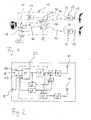
- FIG. 1 A schematic block diagram of an example of a hearing assistance system according to the invention is shown in Fig. 1 .
- the system comprises a transmission unit 10 and at least one receiver unit, wherein in the example of Fig. 1 an analog receiver unit 12 and a digital receiver unit 14 are shown.
- the transmission unit 10 comprises a microphone arrangement 16 for capturing a speaker's voice, which may be integrated within the housing of the transmission unit 10 or which may be connected to it via a cable.
- the transmission unit 10 also may include an audio signal input 18 which serves to connect an external audio signal source 20, such as a mobile phone, an FM radio, a music player, a telephone or a TV device, to the transmission unit 10.
- the audio signals captured by the microphone arrangement 16 and the audio signals optionally received from the external audio signal source 20 are supplied to a digital signal processor (DSP) 22 which is controlled by a microcontroller 24 and which acts as an audio signal processing unit which applies, for example, a gain model to the captured audio signals.
- DSP digital signal processor
- the DSP 22 may serve to analyze the captured audio signals and to generate control data (control commands) according to the result of the analysis of the captured audio signals.
- the processed audio signals and the control data/commands are supplied in parallel both to an analog transmitter 26 and a digital transmitter 28, which are likewise controlled by the microcontroller 24.
- the analog transmitter 26 applies an analog modulation scheme, typically a frequency modulation scheme, to the processed audio signals
- the digital transmitter 28 applies a digital modulation scheme, such as PSK / FSK, ASK or combined amplitude and phase modulations such as QPSK, and variations thereof (e.g. GFSK) to the processed audio signals.
- the analog transmitter 26 transmits the modulated signals via an antenna 30 to an antenna 32 of the analog receiver unit 12, thereby establishing an analog link 34.
- the digital transmitter 28 transmits the modulated signals via an antenna 36 to an antenna 38 of the digital receiver unit 14, thereby establishing a digital link 40.
- Each of the analog receiver unit 12 and the digital receiver unit 14 comprises or is connected to a loudspeaker 42 or another means for stimulating a user's hearing.
- the receiver units 12, 14 are ear-worn devices which are integrated into or connected to a hearing aid comprising the speaker 42.
- the control data transmitted in parallel to the audio signals may serve to control operation of the receiver units 12, 14 according to the presently prevailing auditory scene as detected by the DSP 22 from the audio signal captured by the microphone arrangement 16.
- both the digital transmitter 28 and the digital receiver unit 14 are designed as transceivers, so that the digital transmitter 28 can also receive control data and commands sent from the digital receiver unit 14.
- a typical carrier frequency range for the analog link 34 is around 200 MHz.
- Typical carrier frequencies for the digital link 40 are 865 MHz, 915 MHz and 2.45 GHz.
- the microcontroller 24 is responsible for management of all transmitter components and may implement the wireless communication protocol, in particular for the digital link 40.
- the microphone arrangement 16 comprises two spaced apart microphones 16A and 16B for capturing audio signals which are supplied to an acoustic beam-former unit 44 which generates an output signal supplied to a gain model unit 46.
- the output of the beam-former unit 44 is also supplied to a voice activity detector (VAD) unit 48 which serves to detect whether the speaker is presently speaking or not and which generates a corresponding status output signal.
- VAD voice activity detector
- the output of at least one of the microphones 16A, 16B is also supplied to an ambient noise estimation unit 50 which serves to estimate the ambient noise level and which generates a corresponding output signal.
- the output signals of the units 48 and 50 are supplied to an encoder unit 52 in which the data is encoded by a digital encoder/modulator, e.g. DTMF encoded, in order to produce control data, for example within a range from 5 kHz to 7 kHz.
- the output of the unit 52 and the processed audio signals from the gain model 46 are supplied to an adder unit 54 in which the audio signals and the control data signals are mixed and are supplied as a mixed signal to the analog transmitter 26.
- the processed audio signals from the gain model unit 46 and the output signals of the units 48 and 50 are also applied to a unit 56 which serves to generate a corresponding digital signal which is supplied to the digital transmitter 28.
- the audio signals may be limited to a range of 100 Hz to 5 kHz. Since such bandwidth limitation is not desirable in the audio signals for digital transmission, the audio signals for digital transmission may be differently processed in the unit 46 than the audio signals for analog transmission and may be delivered at a separate output (dashed line at the element 46 in Fig. 2 ).
- the units 44, 46, 48, 50 and 56 may be functionally realized by the DSP 22 (see dashed line surrounding these units in Fig. 2 ).
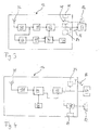
- FIG. 3 A more detailed example of the analog receiver unit 12 is shown in Fig. 3 , according to which the audio signals transmitted via the analog link 34 are received by the antenna 32 and are demodulated in an FM radio receiver 58.
- An audio signal low-path filter 60 operating at 5 kHz applies the audio signals to a variable gain amplifier 62 which controls the gain of the analog audio signal and from where the amplified audio signals are supplied to a hearing aid 64.
- the output signal of the FM radio receiver 58 is also filtered by a high pass filter 66 operating at 5 kHz in order to extract the control data from the unit 52 contained in the FM radio signal.
- the filtered signal is applied to a decoder unit 68 including a DTMF decoder and a digital demodulator/decoder in order to decode the data signals from the units 48 and 50 of the transmission unit 10.
- the control data decoded in the unit 68 are provided separately to a parameter update unit 70 in which the parameters of the commands are updated according to information stored in an EEPROM 72 of the receiver unit 12.
- the output of the parameter update unit 70 is used to control the variable gain amplifier 62 which is gain-controlled. Thereby the audio signal output of the amplifier 62 - and thus the sound pressure level at which the audio signals are finally reproduced - can be controlled according to the result of the auditory scene analysis performed by the transmission unit 10.
- FIG. 4 A more detailed example of the digital receiver unit 14 is shown in Fig. 4 , according to which the signals transmitted via the digital link 40 are received by the antenna 38 and are demodulated in a digital radio receiver 158.
- the demodulated signals are supplied to a DSP 74 which separates the signals into the audio signals and the control data and which is provided for advanced processing, e.g. equalization, of the audio signals according to the information provided by the control data.
- the processed audio signals after digital-to-analog conversion, are supplied to a variable gain amplifier 62 which serves to amplify the audio signals by applying a gain controlled by the control data received via the digital link 40.
- variable gain amplifier may be realized in the digital domain by using a PWM modulator taking over the role of the D/A-converter and the power amplifier.
- the amplified audio signals are supplied to a hearing aid 64.
- the receiver unit 14 also includes a memory 76 for the DSP 74.
- the receiver units 12, 14 may include a power amplifier 78 which may be controlled by a manual volume control 80 and which supplies power amplified audio signals to a loudspeaker 82 which may be an ear-worn element integrated within or connected to the receiver unit 12, 14. Volume control also could be done remotely from the transmission unit 10 or the transmission unit 110 by transmitting corresponding control commands to the receiver units 12, 14.
- the receiver units 12, 14 could be located somewhere in a room in order to supply audio signals to loudspeakers 82 installed in the same room, whereby a speech enhancement system for an audience can be realized (as indicated by dashed lines in Figs. 3 and 4 ).
- receiver maybe a neck-worn device having a transmitter 84 for transmitting the received signals via with an magnetic induction link 86 (analog or digital) to the hearing aid 64 (as indicated by dotted lines in Figs. 3 and 4 )
Landscapes
- Engineering & Computer Science (AREA)
- Physics & Mathematics (AREA)
- Health & Medical Sciences (AREA)
- General Health & Medical Sciences (AREA)
- Neurosurgery (AREA)
- Otolaryngology (AREA)
- Computer Networks & Wireless Communication (AREA)
- Acoustics & Sound (AREA)
- Signal Processing (AREA)
- Circuit For Audible Band Transducer (AREA)
- Transmitters (AREA)
- Stereophonic System (AREA)
- Details Of Audible-Bandwidth Transducers (AREA)
Description
- The invention relates to a system and a method for providing hearing assistance to at least one user, wherein audio signals from an audio signal source, such as a microphone for capturing a speaker's voice, are transmitted via a wireless link to a receiver unit, such as an audio receiver for a hearing aid, from where the audio signals are supplied a means for stimulating the hearing of the user, such as a hearing aid speaker.
- Usually in such systems the wireless audio link is an FM (frequency modulation) radio link. According to a typical application of such wireless audio systems the receiver unit is connected to or integrated into a hearing instrument, such as a hearing aid, with the transmitted audio signals being mixed with audio signals captured by the microphone of the hearing instrument prior to being reproduced by the output transducer of the hearing instrument. The benefit of such systems is that the microphone of the hearing instrument can be supplemented or replaced by a remote microphone which produces audio signals which are transmitted wirelessly to the FM receiver and thus to the hearing instrument. In particular, FM systems have been standard equipment for children with hearing loss in educational settings for many years. Their merit lies in the fact that a microphone placed a few inches from the mouth of a person speaking receives speech at a much higher level than one placed several feet away. This increase in speech level corresponds to an increase in signal-to-noise ratio (SNR) due to the direct wireless connection to the listener's amplification system. The resulting improvements of signal level and SNR in the listener's ear are recognized as the primary benefits of FM radio systems, as hearing-impaired individuals are at a significant disadvantage when processing signals with a poor acoustical SNR.
- A typical application of such wireless audio systems is at school, wherein the teacher uses a wireless microphone for transmitting the captured audio signals via the transmission unit to receiver units worn by the students. Since the receiver units and the respective hearing aids are usually owned by the students, the receiver units may be of different types within a class.
- Another typical application of wireless audio systems is the case in which the transmission unit is designed as an assistive listening device. In this case, the transmission unit may include a wireless microphone for capturing ambient sound, in particular from a speaker close to the user, and/or a gateway to an external audio device, such as a mobile phone; here the transmission unit usually only serves to supply wireless audio signals to the receiver unit(s) worn by the user.
- Examples of analog wireless FM systems particularly suited for school applications are described, for example, in
EP 1 863 320 A1 andWO 2008/138365 A1 . According to these systems, the wireless link does not only serve to transmit audio signals captured by the wireless microphone but in addition also serves to transmit control data obtained from analyzing the audio signals in the transmission unit to the receiver unit(s), with such control data being used in the receiver unit to adjust, for example, the gain applied to the received audio signals according to the prevailing ambient noise and the issue of whether the speaker is presently speaking or not. For transmission of such control data the range between 5 and 7 kHz of the transmitted bandwidth, i.e. a frequency band above the audio signal band, may be used. - In applications where the receiver unit is part of or connected to a hearing aid, transmission is usually carried out by using analog FM technology in the 200 MHz frequency band. In recent systems the analogue FM transmission technology may be replaced by employing digital modulation techniques for audio signal transmission. An example of such digital system is available from the company Comfort Audio AB, 30105 Halmstad, Sweden under the designation "Digisystem", see e.g. http://www.comfortaudio.com/int/Page.asp?PageNumber=41
- A specific example of an analog wireless FM system particularly suited for school applications is described in
WO 2008/074350 A1 , wherein the system consists of a plurality of transmission units comprising a microphone and a plurality of analog FM receiver units and wherein only one of the transmission units has an analog audio signal transmitter, while each of the transmission units is provided with a digital transceiver in order to realize an assistive digital link for enabling communication between the transmission units. The assistive digital link also serves to transmit audio signals captured by a transmission unit not having the analog transmitter to the transmission unit having the analog transmitter from where the audio signals are transmitted via the analog FM link to the receiver units. - Digital audio signal transmission is also used in the field of mobile telephony, wherein it is known to provide a mobile telephone with the option to operate in different networks, for example GSM900 and GSM1800, including services like GPRS and EDGE, and UMTS, including services like HSDPA and HSUPA. However, at a time, always only one of these options is used, depending on the present network.
- It is also known that special security relevant applications, such as navigation systems, flight and/or space communication systems and personal safety systems, may utilize redundant radio systems in order to improve robustness and to guarantee operation also in case of failure of one of the radio units. Naturally, always the same radio technology is used for the redundant link, and only one of the links is operated at the same time.
- In radio-broadcasting or TV-broadcasting it is known to transmit mixed analog and digital signals, see for example
US 6,418,300 B1 ,DE 37 18 906 A1 ,DE 197 17 169 A1 andWO 00/21228 A1 - A hearing assistance system according to the preamble of claim 1 is known from
KR 2007-0089325 - It is an object of the invention to provide for a wireless audio system comprising a transmission unit which provides for particularly flexible operation.
- This object is achieved by a hearing assistance system as defined in claim 1 and a hearing assistance method as defined in claim 15, respectively.
- The invention is beneficial in that, by providing the transmission unit both with an analog transmitter and a digital transmitter in order to transmit the audio signals simultaneously via an analog audio link and a digital audio link, the transmission unit can be used both with analog receiver units and with digital receiver units, which is particularly advantageous in school applications, wherein part of the students may use an analog receiver unit and part of the students may use a digital receiver unit. In particular, the transmission unit thereby is compatible also with the large base of analog receiver units already existing on the market.
- The invention is particularly useful for transmitting audio signals from a wireless microphone to one or more hearing aids, but it also may be used for transmitting audio signals from a wireless microphone or another audio signal source, such as a music player, a mobile phone or a TV (television) unit, to a hearing aid, a headphone or a loudspeaker, such as a speech enhancement system in a room for an audience.
- Preferred embodiments are defined in the dependent claims.
- Hereinafter examples of the invention will be illustrated by reference to the attached drawings, wherein:
- Fig. 1
- is a schematic block diagram of an example of a hearing assistance system according to an invention;
- Fig. 2
- is a more detailed example of the audio signal path in the transmission unit of the system of
Fig. 1 ; - Fig. 3
- is a more detailed block of diagram an example of the analog receiver unit of the system of
Fig. 1 ; and - Fig. 4
- is a more detailed block diagram of an example of the digital receiver unit of the system of
Fig. 1 . - A schematic block diagram of an example of a hearing assistance system according to the invention is shown in
Fig. 1 . The system comprises atransmission unit 10 and at least one receiver unit, wherein in the example ofFig. 1 ananalog receiver unit 12 and adigital receiver unit 14 are shown. - The
transmission unit 10 comprises amicrophone arrangement 16 for capturing a speaker's voice, which may be integrated within the housing of thetransmission unit 10 or which may be connected to it via a cable. Thetransmission unit 10 also may include anaudio signal input 18 which serves to connect an externalaudio signal source 20, such as a mobile phone, an FM radio, a music player, a telephone or a TV device, to thetransmission unit 10. The audio signals captured by themicrophone arrangement 16 and the audio signals optionally received from the externalaudio signal source 20 are supplied to a digital signal processor (DSP) 22 which is controlled by amicrocontroller 24 and which acts as an audio signal processing unit which applies, for example, a gain model to the captured audio signals. - In addition, the DSP 22 may serve to analyze the captured audio signals and to generate control data (control commands) according to the result of the analysis of the captured audio signals. The processed audio signals and the control data/commands are supplied in parallel both to an
analog transmitter 26 and adigital transmitter 28, which are likewise controlled by themicrocontroller 24. Theanalog transmitter 26 applies an analog modulation scheme, typically a frequency modulation scheme, to the processed audio signals, and thedigital transmitter 28 applies a digital modulation scheme, such as PSK / FSK, ASK or combined amplitude and phase modulations such as QPSK, and variations thereof (e.g. GFSK) to the processed audio signals. - The
analog transmitter 26 transmits the modulated signals via anantenna 30 to anantenna 32 of theanalog receiver unit 12, thereby establishing ananalog link 34. Thedigital transmitter 28 transmits the modulated signals via anantenna 36 to anantenna 38 of thedigital receiver unit 14, thereby establishing adigital link 40. Each of theanalog receiver unit 12 and thedigital receiver unit 14 comprises or is connected to aloudspeaker 42 or another means for stimulating a user's hearing. Typically, thereceiver units speaker 42. The control data transmitted in parallel to the audio signals may serve to control operation of thereceiver units DSP 22 from the audio signal captured by themicrophone arrangement 16. - In practice, both the
digital transmitter 28 and thedigital receiver unit 14 are designed as transceivers, so that thedigital transmitter 28 can also receive control data and commands sent from thedigital receiver unit 14. - A typical carrier frequency range for the
analog link 34 is around 200 MHz. Typical carrier frequencies for thedigital link 40 are 865 MHz, 915 MHz and 2.45 GHz. - The
microcontroller 24 is responsible for management of all transmitter components and may implement the wireless communication protocol, in particular for thedigital link 40. - In
Fig. 2 an example of the audio signal path in thetransmission unit 10 is shown in more detail. Themicrophone arrangement 16 comprises two spaced apartmicrophones 16A and 16B for capturing audio signals which are supplied to an acoustic beam-former unit 44 which generates an output signal supplied to again model unit 46. The output of the beam-former unit 44 is also supplied to a voice activity detector (VAD)unit 48 which serves to detect whether the speaker is presently speaking or not and which generates a corresponding status output signal. The output of at least one of themicrophones 16A, 16B is also supplied to an ambientnoise estimation unit 50 which serves to estimate the ambient noise level and which generates a corresponding output signal. The output signals of theunits encoder unit 52 in which the data is encoded by a digital encoder/modulator, e.g. DTMF encoded, in order to produce control data, for example within a range from 5 kHz to 7 kHz. The output of theunit 52 and the processed audio signals from thegain model 46 are supplied to an adder unit 54 in which the audio signals and the control data signals are mixed and are supplied as a mixed signal to theanalog transmitter 26. The processed audio signals from thegain model unit 46 and the output signals of theunits unit 56 which serves to generate a corresponding digital signal which is supplied to thedigital transmitter 28. For the analog transmission the audio signals may be limited to a range of 100 Hz to 5 kHz. Since such bandwidth limitation is not desirable in the audio signals for digital transmission, the audio signals for digital transmission may be differently processed in theunit 46 than the audio signals for analog transmission and may be delivered at a separate output (dashed line at theelement 46 inFig. 2 ). - The
units Fig. 2 ). - A more detailed example of the
analog receiver unit 12 is shown inFig. 3 , according to which the audio signals transmitted via theanalog link 34 are received by theantenna 32 and are demodulated in anFM radio receiver 58. An audio signal low-path filter 60 operating at 5 kHz applies the audio signals to avariable gain amplifier 62 which controls the gain of the analog audio signal and from where the amplified audio signals are supplied to ahearing aid 64. The output signal of theFM radio receiver 58 is also filtered by ahigh pass filter 66 operating at 5 kHz in order to extract the control data from theunit 52 contained in the FM radio signal. The filtered signal is applied to adecoder unit 68 including a DTMF decoder and a digital demodulator/decoder in order to decode the data signals from theunits transmission unit 10. The control data decoded in theunit 68 are provided separately to aparameter update unit 70 in which the parameters of the commands are updated according to information stored in anEEPROM 72 of thereceiver unit 12. The output of theparameter update unit 70 is used to control thevariable gain amplifier 62 which is gain-controlled. Thereby the audio signal output of the amplifier 62 - and thus the sound pressure level at which the audio signals are finally reproduced - can be controlled according to the result of the auditory scene analysis performed by thetransmission unit 10. - A more detailed example of the
digital receiver unit 14 is shown inFig. 4 , according to which the signals transmitted via thedigital link 40 are received by theantenna 38 and are demodulated in adigital radio receiver 158. The demodulated signals are supplied to aDSP 74 which separates the signals into the audio signals and the control data and which is provided for advanced processing, e.g. equalization, of the audio signals according to the information provided by the control data. The processed audio signals, after digital-to-analog conversion, are supplied to avariable gain amplifier 62 which serves to amplify the audio signals by applying a gain controlled by the control data received via thedigital link 40. Alternatively, the variable gain amplifier may be realized in the digital domain by using a PWM modulator taking over the role of the D/A-converter and the power amplifier. The amplified audio signals are supplied to ahearing aid 64. Thereceiver unit 14 also includes amemory 76 for theDSP 74. - Rather than supplying the audio signals amplified by the
variable gain amplifier 62 to the audio input of ahearing aid 64, thereceiver units power amplifier 78 which may be controlled by amanual volume control 80 and which supplies power amplified audio signals to aloudspeaker 82 which may be an ear-worn element integrated within or connected to thereceiver unit transmission unit 10 or the transmission unit 110 by transmitting corresponding control commands to thereceiver units - Alternatively, rather than being ear-worn components, the
receiver units loudspeakers 82 installed in the same room, whereby a speech enhancement system for an audience can be realized (as indicated by dashed lines inFigs. 3 and 4 ). - Another alternative implementation of the receiver maybe a neck-worn device having a
transmitter 84 for transmitting the received signals via with an magnetic induction link 86 (analog or digital) to the hearing aid 64 (as indicated by dotted lines inFigs. 3 and 4 ) - Examples regarding the implementation of the analog part of the hearing assistance system of the present invention can be found in
EP 1 863 320 A1 andWO 2008/138365 A1 . It is to be mentioned that thetransmission unit 10 would not necessarily require a DSP for processing the input signals. Alternatively, the role of themicrocontroller 24 could also be taken over by theDSP 22. Also, signal transmission could be limited to a pure audio signal, without adding control and command data.
Claims (15)
- A system for providing hearing assistance to at least one user, comprising:at least one audio signal source (16, 20) for providing audio signals;a transmission unit (10) for wireless transmission of audio signals;at least one receiver unit (12, 14) for wireless reception of audio signals from the transmission unit;means (42, 82) for stimulating the hearing of the user according to audio signals supplied from the at least one receiver unit,wherein the transmission unit comprises a digital transmitter (28) for applying a digital modulation scheme in order to transmit the audio signals from the audio signal source (16, 20) via a digital audio link (40),characterized in that the transmission unit further comprises an analog transmitter (26) for applying an analog modulation scheme in order to transmit the audio signals from the audio signal source (16, 20) simultaneously via an analog audio link (34) and said digital audio link (40).
- The system of claim 1, wherein the audio signal source is a microphone arrangement (16) integrated into or connected to the transmission unit (10) for capturing a speaker's voice, and wherein the transmission unit (10) comprises an audio signal processing unit (46) for processing the audio signals captured by the microphone arrangement (16) prior to being transmitted.
- The system of claim 2, wherein the audio signal processing unit (22, 46) is for applying a gain model to the captured audio signals.
- The system of one of claims 2 and 3, wherein the transmission unit (10) comprises means (48, 50) for analyzing the captured audio signals and for generating, according to an analysis of the captured audio signals, control data to be transmitted both via the analog link (34) and the digital link (40) together with the audio signals to the receiver unit(s).
- The system of claim 4, wherein the transmission unit (10) comprises at least one of an acoustic beamformer unit (44), a voice activity detector unit (48) and an ambient noise estimation unit (50).
- The system of one of the preceding claims, wherein the analog transmitter (26) is an FM transmitter.
- The system of one of the preceding claims, wherein the digital transmitter (28) is for using at least one of PSK, FSK, ASK or combined amplitude and phase modulations, such as QPSK.
- The system of one of the preceding claims, wherein the transmission unit (10) comprises a microcontroller (24) for controlling both the analog transmitter (26) and the digital transmitter (28).
- The system of one of the preceding claims, wherein the transmission unit (10) is for being connected to an audio device (20), such as a mobile phone, an FM radio, a music player, a telephone, or a TV device, as an external audio signal source.
- The system of one of claims 4 and 5, wherein each receiver unit (12, 14) comprises a variable gain amplifier (26) controlled by the control data received from the transmission unit (10).
- The system of one of the preceding claims, wherein at least one of the receiver units (14) comprises a digital receiver (158) for receiving audio signals from the digital transmitter (28) and at least one of the receiver units (12) comprises an analog receiver (58) for receiving audio signals from the analog transmitter (26).
- The system of one of the preceding claims, wherein the at least one receiver unit (12, 14) is connected to or integrated into an ear-worn device, such as a hearing aid (64), comprising the stimulation means (42).
- The system of one of claims 1 to 11, wherein the at least one receiver unit (12, 14) is a neck-worn device comprising a transmitter (84) for transmitting audio signals via an inductive link to an ear-worn device, such as a hearing aid (64), comprising the stimulation means (42).
- The system of one of claims 1 to 11, wherein the at least one receiver unit (12, 14) is connected to or integrated within at least one audience loudspeaker (82) serving as the stimulation means.
- A method for providing hearing assistance to at least one user, comprising:providing audio signals from at least one audio signal source to a transmission unit (10),transmitting audio signals wirelessly from the transmission unit to at least one receiver unit (12, 14),stimulating the hearing of the user according to audio signals supplied from the at least one receiver unit,wherein the transmission unit comprises a digital transmitter (28) applying a digital modulation scheme for transmitting the audio signals from the audio signal source via a digital audio link (40),characterized in that the transmission unit further comprises an analog transmitter (26) applying an analog modulation scheme for transmitingthe audio signals from the audio signal source (16, 20) simultaneously via an analog audio link (34) and said digital audio link (40).
Applications Claiming Priority (1)
| Application Number | Priority Date | Filing Date | Title |
|---|---|---|---|
| PCT/EP2009/065338 WO2010018235A2 (en) | 2009-11-17 | 2009-11-17 | Hearing assistance system and method |
Publications (2)
| Publication Number | Publication Date |
|---|---|
| EP2502428A2 EP2502428A2 (en) | 2012-09-26 |
| EP2502428B1 true EP2502428B1 (en) | 2014-06-25 |
Family
ID=41669387
Family Applications (1)
| Application Number | Title | Priority Date | Filing Date |
|---|---|---|---|
| EP09751947.4A Not-in-force EP2502428B1 (en) | 2009-11-17 | 2009-11-17 | Hearing assistance system and method |
Country Status (4)
| Country | Link |
|---|---|
| US (1) | US8693715B2 (en) |
| EP (1) | EP2502428B1 (en) |
| DK (1) | DK2502428T3 (en) |
| WO (1) | WO2010018235A2 (en) |
Families Citing this family (9)
| Publication number | Priority date | Publication date | Assignee | Title |
|---|---|---|---|---|
| EP2534853B1 (en) | 2010-02-12 | 2016-11-23 | Sonova AG | Wireless sound transmission system and method |
| DK2552017T3 (en) * | 2011-07-26 | 2018-05-28 | Oticon As | Method of reducing the minimum operating range of a communication connection |
| US9061102B2 (en) | 2012-07-17 | 2015-06-23 | Elwha Llc | Unmanned device interaction methods and systems |
| US20140024999A1 (en) | 2012-07-17 | 2014-01-23 | Elwha LLC, a limited liability company of the State of Delaware | Unmanned device utilization methods and systems |
| CN203039685U (en) * | 2012-12-03 | 2013-07-03 | 瑞声光电科技(常州)有限公司 | Wireless transmission system |
| US10652673B2 (en) * | 2013-05-15 | 2020-05-12 | Gn Hearing A/S | Hearing instrument with an authentication protocol |
| GB201412772D0 (en) * | 2014-07-18 | 2014-09-03 | Lewis Marcus | Microwave and wi-fi transmissions, cable free to multiple speakers |
| TWI654885B (en) | 2015-06-23 | 2019-03-21 | 元鼎音訊股份有限公司 | Hearing aid communication system and hearing aid communication method thereof |
| EP3525487B1 (en) * | 2018-02-09 | 2020-09-16 | Widex A/S | A communication channel between a remote control and a hearing assistive device |
Family Cites Families (19)
| Publication number | Priority date | Publication date | Assignee | Title |
|---|---|---|---|---|
| DE3718906A1 (en) | 1987-06-05 | 1988-12-15 | Philips Patentverwaltung | Method for transmitting an audio signal and device for carrying out the method |
| FR2756686B1 (en) | 1996-11-29 | 1999-02-19 | Thomson Csf | METHOD AND DEVICE FOR ANALOG AND DIGITAL MIXED BROADCASTING OF RADIO TRANSMISSION BROADCASTED BY THE SAME TRANSMITTER |
| DE19717169A1 (en) | 1997-04-23 | 1998-10-29 | Deutsche Telekom Ag | Method and arrangement for an analog-digital simultaneous transmission of radio broadcasts in the AM frequency bands |
| US6292511B1 (en) | 1998-10-02 | 2001-09-18 | Usa Digital Radio Partners, Lp | Method for equalization of complementary carriers in an AM compatible digital audio broadcast system |
| US6765929B1 (en) * | 1999-02-05 | 2004-07-20 | Lucent Technologies Inc. | Method and apparatus for combining signals |
| EP1531650A3 (en) * | 2003-11-12 | 2008-07-09 | Gennum Corporation | Hearing instrument having a wireless base unit |
| WO2005086801A2 (en) * | 2004-03-05 | 2005-09-22 | Etymotic Research, Inc. | Companion microphone system and method |
| CN101124849B (en) * | 2005-01-17 | 2012-07-04 | 唯听助听器公司 | Device and method for operating hearing aid |
| DE102005005603A1 (en) * | 2005-02-07 | 2006-08-17 | Siemens Audiologische Technik Gmbh | Data transmission device for wireless data transmission for hearing aids and corresponding method |
| DK2582158T3 (en) * | 2005-06-05 | 2016-11-28 | Starkey Labs Inc | Communication system for wireless audio devices |
| US7639828B2 (en) * | 2005-12-23 | 2009-12-29 | Phonak Ag | Wireless hearing system and method for monitoring the same |
| EP1819195B1 (en) * | 2006-02-13 | 2009-09-09 | Phonak Communications Ag | Method and system for providing hearing assistance to a user |
| KR20070089325A (en) * | 2006-02-28 | 2007-08-31 | 주식회사 팬택 | Hearing Aid Compatible Mobile Phones |
| DE602006017044D1 (en) | 2006-06-01 | 2010-11-04 | Phonak Ag | Method for setting a hearing aid system |
| WO2008074350A1 (en) | 2006-12-20 | 2008-06-26 | Phonak Ag | Wireless communication system |
| US8345900B2 (en) | 2007-05-10 | 2013-01-01 | Phonak Ag | Method and system for providing hearing assistance to a user |
| US8909147B2 (en) * | 2008-06-23 | 2014-12-09 | Nokia Corporation | Apparatus and method for transmission of audio signals |
| US20100119093A1 (en) * | 2008-11-13 | 2010-05-13 | Michael Uzuanis | Personal listening device with automatic sound equalization and hearing testing |
| US8825037B2 (en) * | 2009-12-22 | 2014-09-02 | Starkey Laboratories, Inc. | FM radio system for digital and analog communications for hearing assistance devices |
-
2009
- 2009-11-17 DK DK09751947.4T patent/DK2502428T3/en active
- 2009-11-17 US US13/508,825 patent/US8693715B2/en not_active Expired - Fee Related
- 2009-11-17 EP EP09751947.4A patent/EP2502428B1/en not_active Not-in-force
- 2009-11-17 WO PCT/EP2009/065338 patent/WO2010018235A2/en not_active Ceased
Also Published As
| Publication number | Publication date |
|---|---|
| WO2010018235A3 (en) | 2010-08-19 |
| DK2502428T3 (en) | 2014-08-04 |
| US20120224732A1 (en) | 2012-09-06 |
| WO2010018235A2 (en) | 2010-02-18 |
| US8693715B2 (en) | 2014-04-08 |
| EP2502428A2 (en) | 2012-09-26 |
Similar Documents
| Publication | Publication Date | Title |
|---|---|---|
| US12212930B2 (en) | Wireless system for hearing communication devices providing wireless stereo reception modes | |
| US8693715B2 (en) | Hearing assistance system and method | |
| US8345900B2 (en) | Method and system for providing hearing assistance to a user | |
| EP2984855B1 (en) | Method and system for providing hearing assistance to a user | |
| US20100195836A1 (en) | Wireless communication system and method | |
| EP1879426A2 (en) | Method and apparatus for a binaural hearing assistance system using monaural audio signals | |
| EP2705675B1 (en) | Self-learning hearing assistance system and method of operating the same | |
| EP1691573A2 (en) | Dynamic hearing assistance system and method therefore | |
| US8825037B2 (en) | FM radio system for digital and analog communications for hearing assistance devices | |
| US20120114158A1 (en) | Hearing assistance system | |
| EP1819195B1 (en) | Method and system for providing hearing assistance to a user | |
| EP2617127B1 (en) | Method and system for providing hearing assistance to a user | |
| US20080240477A1 (en) | Wireless multiple input hearing assist device | |
| US12323766B2 (en) | Binaural hearing system comprising frequency transition | |
| EP2502429B1 (en) | Hearing assistance system and method | |
| EP2317777A1 (en) | Method for operating a hearing device and a hearing device | |
| WO2008052576A1 (en) | Hearing assistance system including data logging capability and method of operating the same |
Legal Events
| Date | Code | Title | Description |
|---|---|---|---|
| PUAI | Public reference made under article 153(3) epc to a published international application that has entered the european phase |
Free format text: ORIGINAL CODE: 0009012 |
|
| 17P | Request for examination filed |
Effective date: 20120618 |
|
| AK | Designated contracting states |
Kind code of ref document: A2 Designated state(s): AT BE BG CH CY CZ DE DK EE ES FI FR GB GR HR HU IE IS IT LI LT LU LV MC MK MT NL NO PL PT RO SE SI SK SM TR |
|
| DAX | Request for extension of the european patent (deleted) | ||
| 17Q | First examination report despatched |
Effective date: 20130408 |
|
| GRAP | Despatch of communication of intention to grant a patent |
Free format text: ORIGINAL CODE: EPIDOSNIGR1 |
|
| INTG | Intention to grant announced |
Effective date: 20140123 |
|
| GRAS | Grant fee paid |
Free format text: ORIGINAL CODE: EPIDOSNIGR3 |
|
| GRAA | (expected) grant |
Free format text: ORIGINAL CODE: 0009210 |
|
| AK | Designated contracting states |
Kind code of ref document: B1 Designated state(s): AT BE BG CH CY CZ DE DK EE ES FI FR GB GR HR HU IE IS IT LI LT LU LV MC MK MT NL NO PL PT RO SE SI SK SM TR |
|
| REG | Reference to a national code |
Ref country code: GB Ref legal event code: FG4D |
|
| REG | Reference to a national code |
Ref country code: CH Ref legal event code: EP |
|
| REG | Reference to a national code |
Ref country code: AT Ref legal event code: REF Ref document number: 675311 Country of ref document: AT Kind code of ref document: T Effective date: 20140715 |
|
| REG | Reference to a national code |
Ref country code: IE Ref legal event code: FG4D |
|
| REG | Reference to a national code |
Ref country code: DK Ref legal event code: T3 Effective date: 20140801 |
|
| REG | Reference to a national code |
Ref country code: DE Ref legal event code: R096 Ref document number: 602009024928 Country of ref document: DE Effective date: 20140807 |
|
| REG | Reference to a national code |
Ref country code: SE Ref legal event code: TRGR |
|
| PG25 | Lapsed in a contracting state [announced via postgrant information from national office to epo] |
Ref country code: GR Free format text: LAPSE BECAUSE OF FAILURE TO SUBMIT A TRANSLATION OF THE DESCRIPTION OR TO PAY THE FEE WITHIN THE PRESCRIBED TIME-LIMIT Effective date: 20140926 Ref country code: FI Free format text: LAPSE BECAUSE OF FAILURE TO SUBMIT A TRANSLATION OF THE DESCRIPTION OR TO PAY THE FEE WITHIN THE PRESCRIBED TIME-LIMIT Effective date: 20140625 Ref country code: LT Free format text: LAPSE BECAUSE OF FAILURE TO SUBMIT A TRANSLATION OF THE DESCRIPTION OR TO PAY THE FEE WITHIN THE PRESCRIBED TIME-LIMIT Effective date: 20140625 Ref country code: CY Free format text: LAPSE BECAUSE OF FAILURE TO SUBMIT A TRANSLATION OF THE DESCRIPTION OR TO PAY THE FEE WITHIN THE PRESCRIBED TIME-LIMIT Effective date: 20140625 Ref country code: NO Free format text: LAPSE BECAUSE OF FAILURE TO SUBMIT A TRANSLATION OF THE DESCRIPTION OR TO PAY THE FEE WITHIN THE PRESCRIBED TIME-LIMIT Effective date: 20140925 |
|
| REG | Reference to a national code |
Ref country code: AT Ref legal event code: MK05 Ref document number: 675311 Country of ref document: AT Kind code of ref document: T Effective date: 20140625 |
|
| REG | Reference to a national code |
Ref country code: NL Ref legal event code: VDEP Effective date: 20140625 |
|
| REG | Reference to a national code |
Ref country code: LT Ref legal event code: MG4D |
|
| PG25 | Lapsed in a contracting state [announced via postgrant information from national office to epo] |
Ref country code: HR Free format text: LAPSE BECAUSE OF FAILURE TO SUBMIT A TRANSLATION OF THE DESCRIPTION OR TO PAY THE FEE WITHIN THE PRESCRIBED TIME-LIMIT Effective date: 20140625 Ref country code: LV Free format text: LAPSE BECAUSE OF FAILURE TO SUBMIT A TRANSLATION OF THE DESCRIPTION OR TO PAY THE FEE WITHIN THE PRESCRIBED TIME-LIMIT Effective date: 20140625 |
|
| PG25 | Lapsed in a contracting state [announced via postgrant information from national office to epo] |
Ref country code: EE Free format text: LAPSE BECAUSE OF FAILURE TO SUBMIT A TRANSLATION OF THE DESCRIPTION OR TO PAY THE FEE WITHIN THE PRESCRIBED TIME-LIMIT Effective date: 20140625 Ref country code: PT Free format text: LAPSE BECAUSE OF FAILURE TO SUBMIT A TRANSLATION OF THE DESCRIPTION OR TO PAY THE FEE WITHIN THE PRESCRIBED TIME-LIMIT Effective date: 20141027 Ref country code: RO Free format text: LAPSE BECAUSE OF FAILURE TO SUBMIT A TRANSLATION OF THE DESCRIPTION OR TO PAY THE FEE WITHIN THE PRESCRIBED TIME-LIMIT Effective date: 20140625 Ref country code: CZ Free format text: LAPSE BECAUSE OF FAILURE TO SUBMIT A TRANSLATION OF THE DESCRIPTION OR TO PAY THE FEE WITHIN THE PRESCRIBED TIME-LIMIT Effective date: 20140625 Ref country code: ES Free format text: LAPSE BECAUSE OF FAILURE TO SUBMIT A TRANSLATION OF THE DESCRIPTION OR TO PAY THE FEE WITHIN THE PRESCRIBED TIME-LIMIT Effective date: 20140625 Ref country code: SK Free format text: LAPSE BECAUSE OF FAILURE TO SUBMIT A TRANSLATION OF THE DESCRIPTION OR TO PAY THE FEE WITHIN THE PRESCRIBED TIME-LIMIT Effective date: 20140625 |
|
| PG25 | Lapsed in a contracting state [announced via postgrant information from national office to epo] |
Ref country code: PL Free format text: LAPSE BECAUSE OF FAILURE TO SUBMIT A TRANSLATION OF THE DESCRIPTION OR TO PAY THE FEE WITHIN THE PRESCRIBED TIME-LIMIT Effective date: 20140625 Ref country code: NL Free format text: LAPSE BECAUSE OF FAILURE TO SUBMIT A TRANSLATION OF THE DESCRIPTION OR TO PAY THE FEE WITHIN THE PRESCRIBED TIME-LIMIT Effective date: 20140625 Ref country code: IS Free format text: LAPSE BECAUSE OF FAILURE TO SUBMIT A TRANSLATION OF THE DESCRIPTION OR TO PAY THE FEE WITHIN THE PRESCRIBED TIME-LIMIT Effective date: 20141025 Ref country code: AT Free format text: LAPSE BECAUSE OF FAILURE TO SUBMIT A TRANSLATION OF THE DESCRIPTION OR TO PAY THE FEE WITHIN THE PRESCRIBED TIME-LIMIT Effective date: 20140625 |
|
| REG | Reference to a national code |
Ref country code: DE Ref legal event code: R097 Ref document number: 602009024928 Country of ref document: DE |
|
| PG25 | Lapsed in a contracting state [announced via postgrant information from national office to epo] |
Ref country code: IT Free format text: LAPSE BECAUSE OF FAILURE TO SUBMIT A TRANSLATION OF THE DESCRIPTION OR TO PAY THE FEE WITHIN THE PRESCRIBED TIME-LIMIT Effective date: 20140625 |
|
| PLBE | No opposition filed within time limit |
Free format text: ORIGINAL CODE: 0009261 |
|
| STAA | Information on the status of an ep patent application or granted ep patent |
Free format text: STATUS: NO OPPOSITION FILED WITHIN TIME LIMIT |
|
| REG | Reference to a national code |
Ref country code: DE Ref legal event code: R119 Ref document number: 602009024928 Country of ref document: DE |
|
| 26N | No opposition filed |
Effective date: 20150326 |
|
| REG | Reference to a national code |
Ref country code: DK Ref legal event code: EBP Effective date: 20141130 |
|
| PG25 | Lapsed in a contracting state [announced via postgrant information from national office to epo] |
Ref country code: MC Free format text: LAPSE BECAUSE OF FAILURE TO SUBMIT A TRANSLATION OF THE DESCRIPTION OR TO PAY THE FEE WITHIN THE PRESCRIBED TIME-LIMIT Effective date: 20140625 Ref country code: LU Free format text: LAPSE BECAUSE OF FAILURE TO SUBMIT A TRANSLATION OF THE DESCRIPTION OR TO PAY THE FEE WITHIN THE PRESCRIBED TIME-LIMIT Effective date: 20141117 |
|
| REG | Reference to a national code |
Ref country code: SE Ref legal event code: EUG Ref country code: CH Ref legal event code: PL |
|
| GBPC | Gb: european patent ceased through non-payment of renewal fee |
Effective date: 20141117 |
|
| PG25 | Lapsed in a contracting state [announced via postgrant information from national office to epo] |
Ref country code: LI Free format text: LAPSE BECAUSE OF NON-PAYMENT OF DUE FEES Effective date: 20141130 Ref country code: SE Free format text: LAPSE BECAUSE OF NON-PAYMENT OF DUE FEES Effective date: 20141118 Ref country code: CH Free format text: LAPSE BECAUSE OF NON-PAYMENT OF DUE FEES Effective date: 20141130 |
|
| REG | Reference to a national code |
Ref country code: IE Ref legal event code: MM4A |
|
| REG | Reference to a national code |
Ref country code: FR Ref legal event code: ST Effective date: 20150731 |
|
| PG25 | Lapsed in a contracting state [announced via postgrant information from national office to epo] |
Ref country code: DK Free format text: LAPSE BECAUSE OF NON-PAYMENT OF DUE FEES Effective date: 20141130 Ref country code: DE Free format text: LAPSE BECAUSE OF NON-PAYMENT OF DUE FEES Effective date: 20150602 Ref country code: GB Free format text: LAPSE BECAUSE OF NON-PAYMENT OF DUE FEES Effective date: 20141117 Ref country code: IE Free format text: LAPSE BECAUSE OF NON-PAYMENT OF DUE FEES Effective date: 20141117 |
|
| PG25 | Lapsed in a contracting state [announced via postgrant information from national office to epo] |
Ref country code: SI Free format text: LAPSE BECAUSE OF FAILURE TO SUBMIT A TRANSLATION OF THE DESCRIPTION OR TO PAY THE FEE WITHIN THE PRESCRIBED TIME-LIMIT Effective date: 20140625 Ref country code: FR Free format text: LAPSE BECAUSE OF NON-PAYMENT OF DUE FEES Effective date: 20141201 |
|
| PG25 | Lapsed in a contracting state [announced via postgrant information from national office to epo] |
Ref country code: SM Free format text: LAPSE BECAUSE OF FAILURE TO SUBMIT A TRANSLATION OF THE DESCRIPTION OR TO PAY THE FEE WITHIN THE PRESCRIBED TIME-LIMIT Effective date: 20140625 |
|
| PG25 | Lapsed in a contracting state [announced via postgrant information from national office to epo] |
Ref country code: BG Free format text: LAPSE BECAUSE OF FAILURE TO SUBMIT A TRANSLATION OF THE DESCRIPTION OR TO PAY THE FEE WITHIN THE PRESCRIBED TIME-LIMIT Effective date: 20140625 |
|
| PG25 | Lapsed in a contracting state [announced via postgrant information from national office to epo] |
Ref country code: BE Free format text: LAPSE BECAUSE OF FAILURE TO SUBMIT A TRANSLATION OF THE DESCRIPTION OR TO PAY THE FEE WITHIN THE PRESCRIBED TIME-LIMIT Effective date: 20140625 Ref country code: HU Free format text: LAPSE BECAUSE OF FAILURE TO SUBMIT A TRANSLATION OF THE DESCRIPTION OR TO PAY THE FEE WITHIN THE PRESCRIBED TIME-LIMIT; INVALID AB INITIO Effective date: 20091117 Ref country code: TR Free format text: LAPSE BECAUSE OF FAILURE TO SUBMIT A TRANSLATION OF THE DESCRIPTION OR TO PAY THE FEE WITHIN THE PRESCRIBED TIME-LIMIT Effective date: 20140625 Ref country code: MT Free format text: LAPSE BECAUSE OF FAILURE TO SUBMIT A TRANSLATION OF THE DESCRIPTION OR TO PAY THE FEE WITHIN THE PRESCRIBED TIME-LIMIT Effective date: 20140625 |
|
| PG25 | Lapsed in a contracting state [announced via postgrant information from national office to epo] |
Ref country code: MK Free format text: LAPSE BECAUSE OF FAILURE TO SUBMIT A TRANSLATION OF THE DESCRIPTION OR TO PAY THE FEE WITHIN THE PRESCRIBED TIME-LIMIT Effective date: 20140625 |