EP2502318B1 - Fuzzy interference relay and method for current differential protection of a transmission line - Google Patents
Fuzzy interference relay and method for current differential protection of a transmission line Download PDFInfo
- Publication number
- EP2502318B1 EP2502318B1 EP09756303.5A EP09756303A EP2502318B1 EP 2502318 B1 EP2502318 B1 EP 2502318B1 EP 09756303 A EP09756303 A EP 09756303A EP 2502318 B1 EP2502318 B1 EP 2502318B1
- Authority
- EP
- European Patent Office
- Prior art keywords
- value
- transmission line
- value equal
- low
- fuzzy
- Prior art date
- Legal status (The legal status is an assumption and is not a legal conclusion. Google has not performed a legal analysis and makes no representation as to the accuracy of the status listed.)
- Not-in-force
Links
Images


Classifications
-
- H—ELECTRICITY
- H02—GENERATION; CONVERSION OR DISTRIBUTION OF ELECTRIC POWER
- H02H—EMERGENCY PROTECTIVE CIRCUIT ARRANGEMENTS
- H02H3/00—Emergency protective circuit arrangements for automatic disconnection directly responsive to an undesired change from normal electric working condition with or without subsequent reconnection ; integrated protection
- H02H3/26—Emergency protective circuit arrangements for automatic disconnection directly responsive to an undesired change from normal electric working condition with or without subsequent reconnection ; integrated protection responsive to difference between voltages or between currents; responsive to phase angle between voltages or between currents
- H02H3/28—Emergency protective circuit arrangements for automatic disconnection directly responsive to an undesired change from normal electric working condition with or without subsequent reconnection ; integrated protection responsive to difference between voltages or between currents; responsive to phase angle between voltages or between currents involving comparison of the voltage or current values at two spaced portions of a single system, e.g. at opposite ends of one line, at input and output of apparatus
- H02H3/30—Emergency protective circuit arrangements for automatic disconnection directly responsive to an undesired change from normal electric working condition with or without subsequent reconnection ; integrated protection responsive to difference between voltages or between currents; responsive to phase angle between voltages or between currents involving comparison of the voltage or current values at two spaced portions of a single system, e.g. at opposite ends of one line, at input and output of apparatus using pilot wires or other signalling channel
- H02H3/307—Emergency protective circuit arrangements for automatic disconnection directly responsive to an undesired change from normal electric working condition with or without subsequent reconnection ; integrated protection responsive to difference between voltages or between currents; responsive to phase angle between voltages or between currents involving comparison of the voltage or current values at two spaced portions of a single system, e.g. at opposite ends of one line, at input and output of apparatus using pilot wires or other signalling channel involving comparison of quantities derived from a plurality of phases, e.g. homopolar quantities; using mixing transformers
-
- H—ELECTRICITY
- H02—GENERATION; CONVERSION OR DISTRIBUTION OF ELECTRIC POWER
- H02H—EMERGENCY PROTECTIVE CIRCUIT ARRANGEMENTS
- H02H3/00—Emergency protective circuit arrangements for automatic disconnection directly responsive to an undesired change from normal electric working condition with or without subsequent reconnection ; integrated protection
- H02H3/26—Emergency protective circuit arrangements for automatic disconnection directly responsive to an undesired change from normal electric working condition with or without subsequent reconnection ; integrated protection responsive to difference between voltages or between currents; responsive to phase angle between voltages or between currents
- H02H3/28—Emergency protective circuit arrangements for automatic disconnection directly responsive to an undesired change from normal electric working condition with or without subsequent reconnection ; integrated protection responsive to difference between voltages or between currents; responsive to phase angle between voltages or between currents involving comparison of the voltage or current values at two spaced portions of a single system, e.g. at opposite ends of one line, at input and output of apparatus
- H02H3/283—Emergency protective circuit arrangements for automatic disconnection directly responsive to an undesired change from normal electric working condition with or without subsequent reconnection ; integrated protection responsive to difference between voltages or between currents; responsive to phase angle between voltages or between currents involving comparison of the voltage or current values at two spaced portions of a single system, e.g. at opposite ends of one line, at input and output of apparatus and taking into account saturation of current transformers
Definitions
- the invention relates to the protection of a transmission line using current measurements obtained with measurements transducers of the current transformer type.
- the invention also concerns transmission line protection systems, and more specifically, current differential protection relay and method for power transmission lines.
- the invention also concerns a method for operating a current differential protection relay electrically coupled to a protection zone of an electrical power transmission line, methods for protecting a zone of a transmission line having current differential protection relays coupled thereto, and a current differential protection relay.
- the protection zone may include parts of a transmission line having two terminal ends.
- a current differential protection system uses only the electrical currents values information obtained from the protected line. Current differential protection requires a comparison of the currents entering and leaving a protected zone of the line.
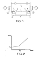
- An example of a current differential protection system of an electrical transmission line is represented on figure 1 .
- Protective relays 2, 4 are located at each end of a protected line 1. Such system may provide phase-segregated current differential protection.
- Circuit breakers 6, 8 and current transformers (CT) 7, 9 are associated, respectively, with relays 2, 4.
- a communication between the relays 2, 4 is made by a communication line 10.
- US 2007/0070565 discloses a relay for current differential protection of at least one transmission line, comprising a calculating function of symmetrical sequence currents, which include zero sequence currents and negative sequence currents of currents of each phase of the transmission line at local and remote ends of the protected transmission line, and a further calculating function which outputs a tripping signal for the control of at least one circuit breaker arranged on the transmission line and associated with the relay.
- each current transformer 7, 9 measures line current values at each ends of the protected line 1, and transmits those values to its associated relay.
- Each relay 2, 4 transmits those values to the relay located at the other end of the line 1, for each phase of the transmission line 1.
- the relay 2 will combine the current value i s given by the current transformer 7 with the line current values i r sent from the remote relay, that is the relay 4, and transmitted on the communication line 10.
- the sum of the currents values is equal to zero when there is no fault, neither on the external line 12 nor on the protected line 1.
- Each relay 2, 4 controls its associated circuit breaker 6, 8 according to a stabilization function in form of an appropriate diff-bias characteristic which represents the tripping conditions of the circuit breakers 6, 8 associated with the relays 2, 4.
- the use of such a diff-bias characteristic prevents relays from undesired line tripping due to differential current resulting from not fully compensated charging current, CT errors, etc.
- a corresponding diff-bias characteristic is shown on figure 2 . According to this characteristic, the trip criteria are:
- I s1 , I s2 , k 1 and k 2 are chosen arbitrarily according to the characteristics of the line to be protected and the desired protection type.
- One embodiment of the invention proposes a relay for current differential protection of at least one transmission line, comprising at least:
- Such current differential protection enables better tripping performances, particularly for cases of external faults with severe CT saturation, when traditional current differential protection may maloperate. It avoids unwanted tripping of healthy transmission line, which may endanger stability of the global power system, especially when the protected line is heavily loaded.
- the current differential protection according to the invention combines strengths of both currents magnitude and phase values comparison criteria.
- the value of the tripping signal which may correspond to a relay stabilization characteristic, is adapted according to the value of the output of the fuzzy inference system which applies fuzzy logic on phase differences of sequence currents combinations.
- Such adaptive stabilization characteristic improves current differential protection performances and ensures higher robustness, in particular for cases of external faults with CT saturation.
- the fuzzy inference system may comprise at least:
- the fuzzyfication unit may convert the phase difference ⁇ 12 into the fuzzy variable ⁇ ( ⁇ 12 ) such that:
- the fuzzyfication unit may convert the phase difference ⁇ 012 into the fuzzy variable ⁇ ( ⁇ 012 ) such that:
- the inference operation unit may perform the inference operation according to the following fuzzy rules base:
- the logical functions "AND” and “OR” of the fuzzy rules base may correspond to operators “Product” and “Maximum” respectively.
- the third calculator may calculate values of bias percentages k 1 and k 2 of a stabilized characteristic which corresponds to the tripping signal such that:
- Another embodiment of the present invention concerns a current differential protection method of at least one transmission line, comprising at least the steps of:
- the fuzzyfication operation may convert the phase difference ⁇ 12 into the fuzzy variable ⁇ ( ⁇ 12 ) such that:
- the fuzzyfication operation may convert the phase difference ⁇ 012 into the fuzzy variable ⁇ ( ⁇ 012 ) such that:
- the inference operation may be performed according to the following fuzzy rules base:
- the invention also concerns a current differential protection system comprising at least two relays as above described, each being coupled to one end of a transmission line and linked to each other with communication means.
- the values of the currents at the local and remote ends of the transmission line may be measured by measurement transducers, for example current transformers arranged on each ends of the transmission line.
- the invention also concerns a method of operating a current differential protection relay electrically coupled to a transmission line, said method comprising the execution of a current differential protection method as above described.
- FIG. 3 shows a schematic view of a current differential protection system 1000 according to a particular embodiment.
- This system comprises two relays 100a, 100b, each being coupled to one end, or terminal, of a transmission line 204 which is the electrical line protected by the system 1000.
- the coupling is made for each phase 204.1 - 204.3 of the transmission line 204, here for the three phases of the line 204.
- Circuit breakers 200.1a - 200.3a and 200.1b-200.3b and current transformers (CT) 202.1a - 202.3a and 202.1b - 202.3b are arranged on each phases 204.1 - 204.3 of the transmission line 204 and are associated, respectively, with relays 100a and 100b.
- CT current transformers
- a communication between the relays 100a and 100b is made by a communication line 206 which is a fiber optic line in this particular embodiment.
- the communication line 206 between the relays 100a, 100b may be of another communication link type, like a multiplexed link for example.
- each current transformer 202.1a - 202.3a, 202.1b - 202.3b measures line current values at each ends of the protected line 204 and transmits those values to its associated relay 100a, 100b.
- Each relay 100a, 100b transmits those values to the relay at the other end of the line 204, for each phase 204.1 - 204.3 of the transmission line 204.
- each relay 100a, 100b combines the local current i s given by the associated current transformers with the remote line current values i r sent from the remote relay.
- Figure 4 shows a schematic view of a relay 100 which corresponds to one of the relays 100a, 100b, according a particular embodiment.
- the operation of the relay 100 is described below for one phase of the transmission line 204, but it is the same for the other phases of the line 204, for example in a three phases electrical power system like the system 1000 represented in figure 3 .
- the signals i s and i r are then filtered with a filter 106, which may be a digital filter using the one cycle Fourier filtering technique which yields the power frequency components of the current waveforms in vector form.
- the vector values of all three phases together with other relevant timing and status information are transmitted over the communication channels to the other ends of the line. This information is considered as remote information for the other(s) relay(s).
- i r and i s are then used by a first calculator 110 for calculating sequence currents, that is zero sequence currents i 0 , positive sequence currents i 1 and negative sequence currents i 2 from the local and remote vector information obtained at the output of the filter 106.
- the negative sequence current i 2 always appear, while the positive sequence current is only subtracted with adequate coefficient k 1g when a three-phase fault occurs. Indeed, for symmetrical faults (that is when the current amplitude in each phase is higher than or equal to around 1.5 per unit in any phase), k 1g is equal to zero. Otherwise, the value of k 1g is chosen non-zero, and, for example, equal to 6.
- i 012 is enriched with zero sequence current to improve detecting ground faults.
- Calculation of combination signals is initiated when the bias current is greater than or equal to 1.5 per unit in any phase. Indeed, like k 1g , for symmetrical faults, k 2p is equal to zero. Otherwise, the value of k 2p is chosen non-zero, and, for example, equal to 6.
- the combination signals i 12 and i 012 are calculated for all sequence currents previously calculated, that is from the local and remote vector information.
- phase differences ⁇ 12 and ⁇ 012 between the combination signals i 12 and i 012 are calculated by a second calculator (which is the first calculator 110 in the example represented in figure 5 ) and outputted from the calculator 110 to a fuzzy inference system 112.
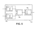
- Figure 5 shows a block diagram of the fuzzy inference system 112, which comprises three main units.
- a first unit 114 is a fuzzyfication unit which converts the input variables, that is ⁇ 12 and ⁇ 012 , into fuzzy variables ⁇ ( ⁇ 12 ) and ⁇ ( ⁇ 012 ) with use of trapezoidal membership functions as represented on figure 6 .
- ⁇ ( ⁇ 12 ) when the value of ⁇ 12 is included between 0° and 75°, ⁇ ( ⁇ 12 ) is “Low” with a value equal to 1 and “High” with a value equal to 0.
- ⁇ ( ⁇ 12 ) is “Low” with a value equal to 0 and "High” with a value equal to 1.
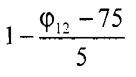
- ⁇ ( ⁇ 12 ) is “Low” with a value equal to 1 - ⁇ 12 - 75 5 and "High” with a value equal to ⁇ 12 - 75 5 .
- ⁇ ( ⁇ 012 ) When the value of ⁇ 012 is included between 0° and 75°, ⁇ ( ⁇ 012 ) is “Low” with a value equal to 1 and “High” with a value equal to 0. When the value of ⁇ 012 is included between 85° and 180°, ⁇ ( ⁇ 012 ) is “Low” with a value equal to 0 and “High” with a value equal to 1. When the value of ⁇ 012 is included between 75° and 85°, ⁇ ( ⁇ 012 ) is “Low” with a value equal to 1 - ⁇ 012 - 75 10 and "High” with a value equal to ⁇ 012 - 75 10 .
- trapezoidal membership functions are used in this embodiment, other types of membership functions may be used to convert phase differences into fuzzy variables (S-shaped, sigmoidal, Z-shaped, triangular membership functions, ).
- a second unit 116 which is an inference operation unit, performs an inference operation on fuzzy variables ⁇ ( ⁇ 12 ) and ⁇ ( ⁇ 012 ) to obtain final fuzzy sets ⁇ (y).
- the fuzzy rules base used by the second unit 116 is composed of three statements:
- the inference method used with the fuzzy rules base may be the PROD-MAX method, in which the operators “Product” and “Maximum” represent the logical functions "AND” and “OR”, respectively.
- other inference methods like MAX-MIN (in which the operators “Minimum” and “Maximum” represent the logical functions “AND” and “OR") or SUM-PROD (in which the operators “Sum” and “Product” represent the logical functions "OR” and “AND) can be used.
- the value y obtained at the output of the fuzzy inference system 112 is then used by a third calculator 120 of the relay 100 to calculate the values of bias percentages k 1 and k 2 of a stabilized characteristic:
Landscapes
- Engineering & Computer Science (AREA)
- Power Engineering (AREA)
- Emergency Protection Circuit Devices (AREA)
Description
- The invention relates to the protection of a transmission line using current measurements obtained with measurements transducers of the current transformer type.
- The invention also concerns transmission line protection systems, and more specifically, current differential protection relay and method for power transmission lines.
- The invention also concerns a method for operating a current differential protection relay electrically coupled to a protection zone of an electrical power transmission line, methods for protecting a zone of a transmission line having current differential protection relays coupled thereto, and a current differential protection relay.
- The protection zone may include parts of a transmission line having two terminal ends.
- A current differential protection system uses only the electrical currents values information obtained from the protected line. Current differential protection requires a comparison of the currents entering and leaving a protected zone of the line. An example of a current differential protection system of an electrical transmission line is represented on
figure 1 .Protective relays protected line 1. Such system may provide phase-segregated current differential protection.Circuit breakers 6, 8 and current transformers (CT) 7, 9 are associated, respectively, withrelays relays communication line 10. -
US 2007/0070565 discloses a relay for current differential protection of at least one transmission line, comprising a calculating function of symmetrical sequence currents, which include zero sequence currents and negative sequence currents of currents of each phase of the transmission line at local and remote ends of the protected transmission line, and a further calculating function which outputs a tripping signal for the control of at least one circuit breaker arranged on the transmission line and associated with the relay. - In operation, each
current transformer protected line 1, and transmits those values to its associated relay. Eachrelay line 1, for each phase of thetransmission line 1. Thus, for each phase, therelay 2 will combine the current value is given by thecurrent transformer 7 with the line current values ir sent from the remote relay, that is therelay 4, and transmitted on thecommunication line 10. The sum of the current values is zero (is + ir = 0) when an external fault appears (for example on an external line 12), while internal faults (on theprotected line 1, between therelays 2, 4) will result in a non-zero combined currents ((is + ir ≠ 0). Moreover, the sum of the currents values is equal to zero when there is no fault, neither on theexternal line 12 nor on theprotected line 1. - Each
relay associated circuit breaker 6, 8 according to a stabilization function in form of an appropriate diff-bias characteristic which represents the tripping conditions of thecircuit breakers 6, 8 associated with therelays figure 2 . According to this characteristic, the trip criteria are: - for |ibias| < IS2, tripping when |idiff| > k1 |ibias| + IS1;
- for |ibias| > IS2, tripping when |idiff| > k2 |ibias| - (k2-k1) IS2 + IS1;
- The values of Is1, Is2, k1 and k2 are chosen arbitrarily according to the characteristics of the line to be protected and the desired protection type.
- Although for most cases this standard protection arrangement is sufficient, there are still cases when the protection may fail, especially for external faults with severe CT saturation due to decaying DC components in fault currents with long time constant.
- Thus there is a need for an improved protection of the transmission lines with improved stabilization for external fault cases, yet with maintained sensitivity and operation speed for internal faults requiring prompt tripping.
- One embodiment of the invention proposes a relay for current differential protection of at least one transmission line, comprising at least:
- a first calculator of symmetrical sequence currents, or symmetrical sequence components, which include zero sequence currents i0, positive sequence currents i1 and negative sequence currents i2, of currents of each phase of the transmission line at local and remote ends of the protected transmission line;
- a second calculator of phase differences ϕ12 and ϕ012 between combination currents i12 and i012 of the symmetrical sequence currents i0, i1 and i2 of each ends of the transmission line;
- a fuzzy inference system which outputs a variable y whose value is calculated according to the values of the phase differences ϕ12 and ϕ012;
- a third calculator which outputs a tripping signal for the control of at least one circuit breaker arranged on the transmission line and associated with the relay, the value of the tripping signal being calculated according to the values of the variable y and the values of the currents of each phase of the transmission line at the local and remote ends of the protected transmission line.
- Such current differential protection enables better tripping performances, particularly for cases of external faults with severe CT saturation, when traditional current differential protection may maloperate. It avoids unwanted tripping of healthy transmission line, which may endanger stability of the global power system, especially when the protected line is heavily loaded.
- The current differential protection according to the invention combines strengths of both currents magnitude and phase values comparison criteria. The value of the tripping signal, which may correspond to a relay stabilization characteristic, is adapted according to the value of the output of the fuzzy inference system which applies fuzzy logic on phase differences of sequence currents combinations. Such adaptive stabilization characteristic improves current differential protection performances and ensures higher robustness, in particular for cases of external faults with CT saturation.
- The combination currents i12 and i012 may be such that:


with k1g = k2p = 0 when the current amplitude in each phase is higher than or equal to around 1.5 per unit in any phase, and k1g and k2p being non-zero real numbers otherwise. - The fuzzy inference system may comprise at least:
- a fuzzyfication unit which may convert the values of the phase differences ϕ12 and ϕ012 into fuzzy variables µ(ϕ12) and µ (ϕ012) ;
- an inference operation unit which may perform inference operation on fuzzy variables µ (ϕ12) and µ(ϕ012) according to a fuzzy rules base and may outputs final fuzzy sets µ(y) as a result of said inference operation;
- a defuzzyfication unit which may convert the final fuzzy sets µ(y) into the variable y by a defuzzyfication operation.
- In this case, the fuzzyfication unit may convert the phase difference ϕ12 into the fuzzy variable µ(ϕ12) such that:
- when the value of ϕ12 is included between 0° and 75°, µ(ϕ12) may be "Low" with a value equal to 1 and "High" with a value equal to 0;
- when the value of ϕ12 is included between 80° and 180°, µ(ϕ12) may be "Low" with a value equal to 0 and "High" with a value equal to 1;
- when the value of ϕ12 is included between 75° and 80°, µ(ϕ12) may be "Low" with a value equal to


- The fuzzyfication unit may convert the phase difference ϕ012 into the fuzzy variable µ(ϕ012) such that:
- when the value of ϕ012 is included between 0° and 75°, µ(ϕ012) may be "Low" with a value equal to 1 and "High" with a value equal to 0;
- when the value of ϕ012 is included between 85° and 180°, µ(ϕ012) may be "Low" with a value equal to 0 and "High" with a value equal to 1;
- when the value of ϕ012 is included between 75° and 85°, µ(ϕ12) may be "Low" with a value equal to


- The inference operation unit may perform the inference operation according to the following fuzzy rules base:
- IF ϕ012 is "High" AND ϕ12 is "High" THEN y is "L";
- IF ϕ012 is "Low" AND ϕ12 is "High" OR ϕ012 is "High" AND ϕ12 is "Low" THEN y is "M";
- IF ϕ012 is "Low" AND ϕ12 is "Low" THEN y is "H";
- with "L", "M" and "H" which are singletons corresponding to
output values - The logical functions "AND" and "OR" of the fuzzy rules base may correspond to operators "Product" and "Maximum" respectively.
- The defuzzyfication operation may be a weighting factor method, the resulting output value y may be expressed by:

with
µL = 1 when y = 0, and µL = 0 otherwise;
µM = 1 when y = 1, and µM = 0 otherwise;
µH = 1 when y = 2, and µL = 0 otherwise. - The third calculator may calculate values of bias percentages k1 and k2 of a stabilized characteristic which corresponds to the tripping signal such that:
- k1 = 0.3 + 0.8y when the parameter y is higher than around 1.5, and k1 = 0.3 otherwise;

- the tripping conditions of the circuit breaker being:
- for |ibias| < IS2, tripping when |idiff| > k1 |ibias| + IS1;
- for |ibias| I > IS2, tripping when |idiff| > k2|ibias| - (k2-k1) IS2 + IS1;
- with, for each phase of the transmission line:
- |ibias| = 0.5(|is| + |ir|) and
- |idiff| = |is + ir|, with
- is: current at the local end of the protected transmission line;
- ir: current at the remote end of the protected transmission line;
- IS1, IS2: non-zero positive real numbers.
- Another embodiment of the present invention concerns a current differential protection method of at least one transmission line, comprising at least the steps of:
- calculating symmetrical sequence currents, which include zero sequence currents i0, positive sequence currents i1 and negative sequence currents i2, of currents of each phase of the transmission line at local and remote ends of the protected transmission line;
- calculating phase differences ϕ12 and ϕ012 between combination currents i12 and i012 of the symmetrical sequence currents i0, i1 and i2 of each ends of the transmission line;
- applying a fuzzy inference method on the phase differences ϕ12 and ϕ012 which output a variable y whose value is calculated according to the values of the phase differences ϕ12 and ϕ012;
- calculating a value of a tripping signal for the control of at least one circuit breaker arranged on the transmission line according to the values of the variable y and the values of the currents of each phase of the transmission line at the local and remote ends of the protected transmission line.
- The fuzzy inference method may comprise at least the steps of:
- fuzzyfication operation which may convert the values of the phase differences ϕ12 and ϕ012 into fuzzy variables µ(ϕ12) and µ(ϕ012);
- inference operation on fuzzy variables µ(ϕ12) and µ(ϕ012) according to a fuzzy rules base to output final fuzzy sets µ(y);
- defuzzyfication operation which may convert the final fuzzy sets µ(y) into the variable y.
- The fuzzyfication operation may convert the phase difference ϕ12 into the fuzzy variable µ(ϕ12) such that:
- when the value of ϕ12 is included between 0° and 75°, µ(ϕ12) may be "Low" with a value equal to 1 and "High" with a value equal to 0;
- when the value of ϕ12 is included between 80° and 180°, µ(ϕ12) may be "Low" with a value equal to 0 and "High" with a value equal to 1;
- when the value of ϕ12 is included between 75° and 80°, µ(ϕ12) may be "Low" with a value equal to


- The fuzzyfication operation may convert the phase difference ϕ012 into the fuzzy variable µ(ϕ012) such that:
- when the value of ϕ012 is included between 0° and 75°, µ(ϕ012) may be "Low" with a value equal to 1 and "High" with a value equal to 0;
- when the value of ϕ012 is included between 85° and 180°, µ(ϕ012) may be "Low" with a value equal to 0 and "High" with a value equal to 1;
- when the value of ϕ012 is included between 75° and 85°, µ(ϕ12) may be "Low" with a value equal to


- The inference operation may be performed according to the following fuzzy rules base:
- IF ϕ012 is "High" AND ϕ12 is "High" THEN y is "L";
- IF ϕ012 is "Low" AND ϕ12 is "High" OR ϕ012 is "High" AND ϕ12 is "Low" THEN y is "M";
- IF ϕ012 is "Low" AND ϕ12 is "Low" THEN y is "H";
- The values of bias percentages k1 and k2 of a stabilized characteristic which corresponds to the tripping signal may be calculated such that:


the tripping conditions of the circuit breaker being: - for |ibias| I < IS2, tripping when |idiff| I > k1 |ibias| I + IS1;
- for I ibias| > IS2, tripping when |idiff| > k2 |ibias| - (k2-k1) IS2 + IS1;
- |ibias| = 0.5(|is| + |ir|) and
- |idiff| = |is + ir|, with
- iε: current at the local end of the protected transmission line;
- ir: current at the remote end of the protected transmission line;
- IS1, IS2: non-zero positive real numbers.
- The invention also concerns a current differential protection system comprising at least two relays as above described, each being coupled to one end of a transmission line and linked to each other with communication means.
- The values of the currents at the local and remote ends of the transmission line may be measured by measurement transducers, for example current transformers arranged on each ends of the transmission line.
- The invention also concerns a method of operating a current differential protection relay electrically coupled to a transmission line, said method comprising the execution of a current differential protection method as above described.
- This invention will be better understood upon reading the description of exemplary embodiments given for purely illustrative and non-limiting purposes, with reference to the appended drawings, in which:
-
figure 1 shows a current differential protection system of a electrical transmission line of the prior art; -
figure 2 shows a stabilization function of a current differential protection relay; -
figure 3 shows a current differential protection system for a two ends transmission line, according to a particular embodiment of the invention; -
figure 4 shows a relay, according to a particular embodiment of the invention, of a current differential protection system; -
figure 5 shows a block diagram of a fuzzy inference system of a relay, according to a particular embodiment of the invention; -
figure 6 shows trapezoidal membership functions used by a fuzzyfication unit of a fuzzyfication inference system of a relay, according to a particular embodiment of the invention; -
figure 7 shows final fuzzy sets got with an inference operation unit of a fuzzyfication inference system of a relay, according to a particular embodiment of the invention. - Identical, similar or equivalent portions of the figures described below bear the same numeric references so as to facilitate moving from one figure to another.
- The various portions shown in the figures are not necessarily shown according to one uniform scale, in order to render the figures more legible.
- The various possibilities (alternatives and embodiments) should be understood as not being mutually exclusive and can be combined with one another.
-
Figure 3 shows a schematic view of a currentdifferential protection system 1000 according to a particular embodiment. This system comprises tworelays transmission line 204 which is the electrical line protected by thesystem 1000. The coupling is made for each phase 204.1 - 204.3 of thetransmission line 204, here for the three phases of theline 204. Circuit breakers 200.1a - 200.3a and 200.1b-200.3b and current transformers (CT) 202.1a - 202.3a and 202.1b - 202.3b are arranged on each phases 204.1 - 204.3 of thetransmission line 204 and are associated, respectively, withrelays relays communication line 206 which is a fiber optic line in this particular embodiment. However, thecommunication line 206 between therelays - In operation, each current transformer 202.1a - 202.3a, 202.1b - 202.3b measures line current values at each ends of the protected
line 204 and transmits those values to its associatedrelay relay line 204, for each phase 204.1 - 204.3 of thetransmission line 204. Thus, for each phase, eachrelay -
Figure 4 shows a schematic view of arelay 100 which corresponds to one of therelays relay 100 is described below for one phase of thetransmission line 204, but it is the same for the other phases of theline 204, for example in a three phases electrical power system like thesystem 1000 represented infigure 3 . - The
relay 100 comprises afirst input 102 for receiving, for each phase, the current is measured by its associated current transformer and asecond input 104 for receiving line current values ir from the remote relay at the opposite end of the protected zone of thetransmission line 204. The current at each line end may be measured by sampling at a fixed frequency. The data samples represent the instantaneous values of the current waveforms, and may contain dc offset, harmonics and high frequency components. - The signals is and ir are then filtered with a
filter 106, which may be a digital filter using the one cycle Fourier filtering technique which yields the power frequency components of the current waveforms in vector form. The vector values of all three phases together with other relevant timing and status information are transmitted over the communication channels to the other ends of the line. This information is considered as remote information for the other(s) relay(s). Based on the local and received vector information, differential currents idiff and bias, or stabilization, currents ibias are calculated by acalculation unit 108 such that, for each phase:
and
- The values of ir and is are then used by a
first calculator 110 for calculating sequence currents, that is zero sequence currents i0, positive sequence currents i1 and negative sequence currents i2 from the local and remote vector information obtained at the output of thefilter 106. The sequence currents are, for the remote vector information:


with a = 1∠120°, and ira, irb, irc which correspond respectively to current at the remote end for each of the three phases a, b and c. - For the local vector information, the sequence currents are:


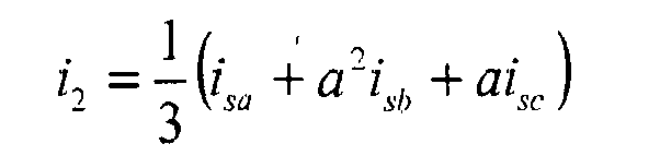
with isa, isb, isc which correspond respectively to local current of each of the three phases a, b and c. - These sequence currents are then used by the
first calculator 110 to obtain the value of a first combination signal i12:
i12 is the combination of the negative sequence current i2 with the positive sequence current i1. In this combination, the negative sequence current i2 always appear, while the positive sequence current is only subtracted with adequate coefficient k1g when a three-phase fault occurs. Indeed, for symmetrical faults (that is when the current amplitude in each phase is higher than or equal to around 1.5 per unit in any phase), k1g is equal to zero. Otherwise, the value of k1g is chosen non-zero, and, for example, equal to 6. - A second combination signal i012 is also calculated by the second calculator 110:

- Thus, compared with i12, i012 is enriched with zero sequence current to improve detecting ground faults. Calculation of combination signals is initiated when the bias current is greater than or equal to 1.5 per unit in any phase. Indeed, like k1g, for symmetrical faults, k2p is equal to zero. Otherwise, the value of k2p is chosen non-zero, and, for example, equal to 6.
- The combination signals i12 and i012 are calculated for all sequence currents previously calculated, that is from the local and remote vector information.
- Then the values of phase differences ϕ12 and ϕ012 between the combination signals i12 and i012 are calculated by a second calculator (which is the
first calculator 110 in the example represented infigure 5 ) and outputted from thecalculator 110 to afuzzy inference system 112. -
Figure 5 shows a block diagram of thefuzzy inference system 112, which comprises three main units. Afirst unit 114 is a fuzzyfication unit which converts the input variables, that is ϕ12 and ϕ012, into fuzzy variables µ(ϕ12) and µ(ϕ012) with use of trapezoidal membership functions as represented onfigure 6 . - Thus, when the value of ϕ12 is included between 0° and 75°, µ(ϕ12) is "Low" with a value equal to 1 and "High" with a value equal to 0. When the value of ϕ12 is included between 80° and 180°, then µ(ϕ12) is "Low" with a value equal to 0 and "High" with a value equal to 1. When the value of ϕ12 is included between 75° and 80°, µ(ϕ12) is "Low" with a value equal to


- When the value of ϕ012 is included between 0° and 75°, µ(ϕ012) is "Low" with a value equal to 1 and "High" with a value equal to 0. When the value of ϕ012 is included between 85° and 180°, µ(ϕ012) is "Low" with a value equal to 0 and "High" with a value equal to 1. When the value of ϕ012 is included between 75° and 85°, µ(ϕ012) is "Low" with a value equal to


- Although trapezoidal membership functions are used in this embodiment, other types of membership functions may be used to convert phase differences into fuzzy variables (S-shaped, sigmoidal, Z-shaped, triangular membership functions, ...).
- Then, a
second unit 116, which is an inference operation unit, performs an inference operation on fuzzy variables µ(ϕ12) and µ(ϕ012) to obtain final fuzzy sets µ(y). In this embodiment, the fuzzy rules base used by thesecond unit 116 is composed of three statements: - IF ϕ012 is "High" AND ϕ12 is "High" THEN µ(y) is "L";
- IF ϕ012 is "Low" AND ϕ12 is "High" OR ϕ012 is "High" AND ϕ12 is "Low" THEN µ(y) is "M";
- IF ϕ012 is "Low" AND ϕ12 is "Low" THEN µ(y) is "H";
- The inference method used with the fuzzy rules base may be the PROD-MAX method, in which the operators "Product" and "Maximum" represent the logical functions "AND" and "OR", respectively. However, other inference methods, like MAX-MIN (in which the operators "Minimum" and "Maximum" represent the logical functions "AND" and "OR") or SUM-PROD (in which the operators "Sum" and "Product" represent the logical functions "OR" and "AND") can be used.
- Finally, a
third unit 118 performs a defuzzyfication operation which converts the final fuzzy sets µ(y) back to respective crisp values by the use of a weighting factor method, the resulting crisp value being expressed by:
with - µL = 1 when y = 0, and µL = 0 otherwise;
- µM = 1 when y = 1, and µM = 0 otherwise;
- µH = 1 when y = 2, and µL = 0 otherwise.
- The value y obtained at the output of the
fuzzy inference system 112 is then used by athird calculator 120 of therelay 100 to calculate the values of bias percentages k1 and k2 of a stabilized characteristic: - k1 = 0.3 + 0.8y when the parameter y is higher than around 1.5, and k1 = 0.3 otherwise;

- Thus the tripping conditions of the
relay 100 are: - For |ibias| < IS2, tripping when |idiff| > k1 |ibias| + IS1;
- For |ibias| > IS2, tripping when |idiff| > k2 |ibias| - (k2-k1) IS2 + IS1;


k1, k2: bias percentages.
Claims (19)
- A relay (100, 100a, 100b) for current differential protection of at least one transmission line (204), comprising at least:a first calculator (110) of symmetrical sequence currents, which include zero sequence currents i0, positive sequence currents i1 and negative sequence currents i2, of currents of each phase (204.1, 204.2, 204.3) of the transmission line (204) at local and remote ends of the protected transmission line (204);a second calculator (110) of phase differences ϕ12 and ϕ012 between combinations currents i12 and i012 of the symmetrical sequence currents i0, i1 and i2 of each ends of the transmission line (204);a fuzzy inference system (112) which outputs a variable y whose value is calculated according to the values of the phase differences ϕ12 and ϕ012;a third calculator (120) which outputs a tripping signal for the control of at least one circuit breaker (200.1a, 200.2a, 200.3a, 200.1b, 200.2b, 200.3b) arranged on the transmission line (204) and associated with the relay (100, 100a, 100b), the value of the tripping signal being calculated according to the values of the variable y and the values of the currents of each phase (204.1, 204.2, 204.3) of the transmission line (204) at the local and remote ends of the protected transmission line (204).
- The relay (100, 100a, 100b) according to claim 1, wherein the combination currents i12 and i012 are such that:


with k1g = k2p = 0 when the current amplitude in each phase is higher than or equal to around 1.5 per unit in any phase, and k1g and k2p being non-zero real numbers otherwise. - The relay (100, 100a, 100b) according to one of previous claims, wherein the fuzzy inference system (112) comprises at least:- a fuzzyfication unit (114) which converts the values of the phase differences ϕ12 and ϕ012 into fuzzy variables µ(ϕ12) and µ(ϕ012);- an inference operation unit (116) which performs inference operation on fuzzy variables µ(ϕ12) and µ(ϕ012) according to a fuzzy rules base and outputs final fuzzy sets µ(y) as a result of said inference operation;- a defuzzyfication unit (118) which converts the final fuzzy sets µ(y) into the variable y by a defuzzyfication operation.
- The relay (100, 100a, 100b) according to claim 3, wherein the fuzzyfication unit (114) converts the phase difference ϕ12 into the fuzzy variable µ(ϕ12) such that:- when the value of ϕ12 is included between 0° and 75°, µ(ϕ12) is "Low" with a value equal to 1 and "High" with a value equal to 0;- when the value of ϕ12 is included between 80° and 180°, µ(ϕ12) is "Low" with a value equal to 0 and "High" with a value equal to 1;- when the value of ϕ12 is included between 75° and 80°, µ(ϕ12) is "Low" with a value equal to


- The relay (100, 100a, 100b) according to one of claims 3 or 4, wherein the fuzzyfication unit (114) converts the phase difference ϕ012 into the fuzzy variable µ(ϕ012) such that:- when the value of ϕ012 is included between 0° and 75°, µ(ϕ012) is "Low" with a value equal to 1 and "High" with a value equal to 0;- when the value of ϕ012 is included between 85° and 180°, µ(ϕ012) is "Low" with a value equal to 0 and "High" with a value equal to 1;- when the value of ϕ012 is included between 75° and 85°, µ(ϕ12) is "Low" with a value equal to


- The relay (100, 100a, 100b) according to one of claims 3 to 5, wherein the inference operation unit (116) performs the inference operation according to the following fuzzy rules base:IF ϕ012 is "High" AND ϕ12 is "High" THEN y is "L";IF ϕ012 is "Low" AND ϕ12 is "High" OR ϕ012 is "High" AND ϕ12 is "Low" THEN y is "M";IF ϕ012 is "Low" AND ϕ12 is "Low" THEN y is "H";with "L", "M" and "H" which are singletons corresponding to output values 0, 1 and 2 respectively.
- The relay (100, 100a, 100b) according to claim 6, wherein the logical functions "AND" and "OR" of the fuzzy rules base correspond to operators "Product" and "Maximum" respectively.
- The relay (100, 100a, 100b) according to one of claims 3 to 7, wherein the defuzzyfication operation is a weighting factor method, the resulting output value y being expressed by:

with
µL = 1 when y = 0, and µL = 0 otherwise;
µM = 1 when y = 1, and µM = 0 otherwise;
µH = 1 when y = 2, and µL = 0 otherwise. - The relay (100, 100a, 100b) according to one of previous claims, wherein the third calculator (120) calculates values of bias percentages k1 and k2 of a stabilized characteristic which corresponds to the tripping signal such that:k1 = 0.3 + 0.8y when the parameter y is higher than around 1.5, and k1 = 0.3 otherwise;
 the tripping conditions of the circuit breaker (200.1a, 200.2a, 200.3a, 200.1b, 200.2b, 200.3b) being:for |ibias| < IS2, tripping when |idiff| > k1 |ibias| + IS1;for |ibias| > IS2, tripping when |idiff| I > k2 |ibias| - (k2-k1) IS2 + IS1;
with, for each phase (204.1, 204.2, 204.3) of the transmission line (204):
and
withis: current at the local end of the protected transmission line (204);ir: current at the remote end of the protected transmission line (204);IS1, IS2: non-zero positive real numbers. - A current differential protection method of at least one transmission line (204), comprising at least the steps of:- calculating symmetrical sequence currents, which include zero sequence currents i0, positive sequence currents i1 and negative sequence currents i2, of currents of each phase (204.1, 204.2, 204.3) of the transmission line (204) at local and remote ends of the protected transmission line (204);- calculating phase differences ϕ12 and ϕ012 between combination currents i12 and i012 of the symmetrical sequence currents i0, i1 and i2 of each ends of the transmission line (204);- applying a fuzzy inference method on the phase differences ϕ12 and ϕ012, outputting a variable y whose value is calculated according to the values of the phase differences ϕ12 and ϕ012;- calculating a value of a tripping signal for the control of at least one circuit breaker (200.1a, 200.2a, 200.3a, 200.1b, 200.2b, 200.3b) arranged on the transmission line (204) according to the values of the variable y and the values of the currents of each phase (204.1, 204.2, 204.3) at the local and remote ends of the protected transmission line (204).
- The method according to claim 10, wherein the combination currents i12 and i012 are such that:


with k1g = k2p = 0 when the current amplitude in each phase is higher than or equal to around 1.5 per unit in any phase, and k1g and k2p being non-zero real numbers otherwise. - The method according to one of claims 10 or 11, wherein the fuzzy inference method comprises at least the steps of:- fuzzyfication operation which converts the values of the phase differences ϕ12 and ϕ012 into fuzzy variables µ(ϕ12) and µ(ϕ012);- inference operation on fuzzy variables µ(ϕ12) and µ(ϕ012) according to a fuzzy rules base to output a final fuzzy sets µ(y);- defuzzyfication operation which converts the final fuzzy sets µ(y) into the variable y.
- The method according to claim 12, wherein the fuzzyfication operation converts the phase difference ϕ12 into the fuzzy variable µ(ϕ12) such that:- when the value of ϕ12 is included between 0° and 75°, µ(ϕ12) is "Low" with a value equal to 1 and "High" with a value equal to 0;- when the value of ϕ12 is included between 80° and 180°, µ(ϕ12) is "Low" with a value equal to 0 and "High" with a value equal to 1;- when the value of ϕ12 is included between 75° and 80°, µ(ϕ12) is "Low" with a value equal to

- The method according to one of claims 12 or 13, wherein the fuzzyfication operation converts the phase difference ϕ012 into the fuzzy variable µ(ϕ012) such that:- when the value of ϕ012 is included between 0° and 75°, µ(ϕ012) is "Low" with a value equal to 1 and "High" with a value equal to 0;- when the value of ϕ012 is included between 85° and 180°, µ(ϕ012) is "Low" with a value equal to 0 and "High" with a value equal to 1;- when ϕ012 is included between 75° and 85°, µ(ϕ12) is "Low" with a value equal to


- The method according to one of claims 12 to 14, wherein the inference operation is performed according to the following fuzzy rules base:IF ϕ012 is "High" AND ϕ12 is "High" THEN y is "L";IF ϕ012 is "Low" AND ϕ12 is "High" OR ϕ012 is "High" AND ϕ12 is "Low" THEN y is "M";IF ϕ012 is "Low" AND ϕ12 is "Low" THEN y is "H";with "L", "M" and "H" which are singletons corresponding to output values 0, 1 and 2 respectively.
- The method according to claim 15, wherein the logical functions "AND" and "OR" of the fuzzy rules base correspond to operators "Product" and "Maximum" respectively.
- The method according to one of claims 12 to 16, wherein the defuzzyfication operation is a weighting factor method, the resulting output value y being expressed by:

with
µL = 1 when y = 0, and µL = 0 otherwise;
µM = 1 when y = 1, and µM = 0 otherwise;
µH = 1 when y = 2, and µL = 0 otherwise. - The method according to one of claims 10 to 17, wherein the values of bias percentages k1 and k2 of a stabilized characteristic which corresponds to the tripping signal are calculated such that:k1 = 0.3 + 0.8y when the parameter y is higher than around 1.5, and k1 = 0.3 otherwise;
 the tripping conditions of the circuit breaker (200.1a, 200.2a, 200.3a, 200.1b, 200.2b, 200.3b) being:for |ibias| < IS2, tripping when |idiff| > k1 |ibias| + IS1;for |ibias| > IS2, tripping when |idiff| > k2 |ibias| - (k2-k1) IS2 + IS1;with, for each phase (204.1, 204.2, 204.3) of the transmission line (204):
and
withis: current at the local end of the protected transmission line (204);ir: current at the remote end of the protected transmission line (204);IS1, IS2: non-zero positive real numbers. - Current differential protection system (1000) comprising at least two relays (100a, 100b) according to one of claims 1 to 9, each being coupled to one end of a transmission line (204) and linked to the each other with communication means (206).
Priority Applications (1)
| Application Number | Priority Date | Filing Date | Title |
|---|---|---|---|
| PL09756303T PL2502318T3 (en) | 2009-11-17 | 2009-11-17 | Fuzzy interference relay and method for current differential protection of a transmission line |
Applications Claiming Priority (1)
| Application Number | Priority Date | Filing Date | Title |
|---|---|---|---|
| PCT/EP2009/065340 WO2011060814A1 (en) | 2009-11-17 | 2009-11-17 | Fuzzy interference relay and method for current differential protection of a transmission line |
Publications (2)
| Publication Number | Publication Date |
|---|---|
| EP2502318A1 EP2502318A1 (en) | 2012-09-26 |
| EP2502318B1 true EP2502318B1 (en) | 2013-09-11 |
Family
ID=42262034
Family Applications (1)
| Application Number | Title | Priority Date | Filing Date |
|---|---|---|---|
| EP09756303.5A Not-in-force EP2502318B1 (en) | 2009-11-17 | 2009-11-17 | Fuzzy interference relay and method for current differential protection of a transmission line |
Country Status (7)
| Country | Link |
|---|---|
| US (1) | US20120224287A1 (en) |
| EP (1) | EP2502318B1 (en) |
| CN (1) | CN102696161A (en) |
| CA (1) | CA2780750A1 (en) |
| ES (1) | ES2434992T3 (en) |
| PL (1) | PL2502318T3 (en) |
| WO (1) | WO2011060814A1 (en) |
Families Citing this family (6)
| Publication number | Priority date | Publication date | Assignee | Title |
|---|---|---|---|---|
| CN103474971B (en) * | 2012-06-06 | 2016-03-23 | 施耐德电器工业公司 | Based on the multi-point circuit guide wire differential protection than facies principle |
| EP2984719B1 (en) * | 2013-04-07 | 2020-05-27 | ABB Power Grids Switzerland AG | A method for detecting fault and current differential protection system thereof |
| US11143715B2 (en) * | 2019-08-15 | 2021-10-12 | Schweitzer Engineering Laboratories, Inc. | Broken conductor detection in a multiple-phase electric power delivery system |
| US12153079B2 (en) | 2022-04-18 | 2024-11-26 | Schweitzer Engineering Laboratories, Inc. | Identifying conductor breaks by detecting series arcing |
| US12362556B2 (en) | 2023-03-07 | 2025-07-15 | Schweitzer Engineering Laboratories, Inc. | Single-ended broken conductor detection logic using incremental quantities |
| US12461171B2 (en) | 2023-11-07 | 2025-11-04 | Schweitzer Engineering Laboratories, Inc. | Single phase broken conductor detection |
Family Cites Families (6)
| Publication number | Priority date | Publication date | Assignee | Title |
|---|---|---|---|---|
| US6590397B2 (en) * | 2000-10-19 | 2003-07-08 | Schweitzer Engineering Laboratories, Inc. | Line differential protection system for a power transmission line |
| US6518767B1 (en) * | 2000-10-19 | 2003-02-11 | Schweitzer Engineering Laboratories, Inc. | Line differential protection system for a power transmission line |
| US6525543B1 (en) * | 2000-10-20 | 2003-02-25 | Schweitzer Engineering Laboratories | Fault type selection system for identifying faults in an electric power system |
| US7660088B2 (en) * | 2005-09-07 | 2010-02-09 | Schweitzer Engineering Laboratories, Inc. | System, apparatus and method for compensating the sensitivity of a sequence element in a line current differential relay in a power system |
| US7903381B2 (en) * | 2008-03-11 | 2011-03-08 | Schweitzer Engineering Laboratories, Inc. | Negative sequence differential element |
| CN101599635B (en) * | 2009-03-17 | 2011-03-16 | 国电南瑞科技股份有限公司 | Method for enhancing differential protection performance by coordination of mutation quantity fault discrimination and fuzzy harmonic analysis |
-
2009
- 2009-11-17 ES ES09756303T patent/ES2434992T3/en active Active
- 2009-11-17 CN CN2009801632720A patent/CN102696161A/en active Pending
- 2009-11-17 CA CA2780750A patent/CA2780750A1/en not_active Abandoned
- 2009-11-17 EP EP09756303.5A patent/EP2502318B1/en not_active Not-in-force
- 2009-11-17 US US13/509,983 patent/US20120224287A1/en not_active Abandoned
- 2009-11-17 PL PL09756303T patent/PL2502318T3/en unknown
- 2009-11-17 WO PCT/EP2009/065340 patent/WO2011060814A1/en not_active Ceased
Also Published As
| Publication number | Publication date |
|---|---|
| PL2502318T3 (en) | 2014-03-31 |
| CN102696161A (en) | 2012-09-26 |
| CA2780750A1 (en) | 2011-05-26 |
| EP2502318A1 (en) | 2012-09-26 |
| ES2434992T3 (en) | 2013-12-18 |
| US20120224287A1 (en) | 2012-09-06 |
| WO2011060814A1 (en) | 2011-05-26 |
Similar Documents
| Publication | Publication Date | Title |
|---|---|---|
| US6256592B1 (en) | Multi-ended fault location system | |
| US9425609B2 (en) | Method and apparatus for differential protection of an electric connection | |
| US6603298B2 (en) | System for estimating the frequency of the power signal on a power transmission line | |
| US9118181B2 (en) | Method of fault phase selection and fault type determination | |
| AU2004201474B2 (en) | Protective relay capable of protecting applications without protection settings | |
| GB2345810A (en) | Detecting faults on an electrical power line | |
| US20120224287A1 (en) | Fuzzy interference relay and method for current differential protection of a transmission line | |
| US4261038A (en) | Protection of electrical power supply systems | |
| KR102057201B1 (en) | Out of order discrimination apparatus and protective relay apparatus | |
| KR100949003B1 (en) | Current differential protection relay | |
| Gangadharan et al. | Influence of current transformer saturation on line current differential protection algorithms | |
| JPS5893422A (en) | Protecting device for high voltage transmission line | |
| EP2328249B1 (en) | Reclosing method for electrical power transmission line | |
| CN102204050B (en) | Differential protection method and differential protection device | |
| EP0952654B1 (en) | Bus-bar protective relay apparatus | |
| EP1237249B9 (en) | Protection relay | |
| AU2001269667A1 (en) | Current compensation method and device for power system protection | |
| US11962140B2 (en) | Coordination of protective elements in an electric power system | |
| Rizvi et al. | Using symmetrical components for internal external fault discrimination in differential protection schemes | |
| Sidhu et al. | Accelerated trip scheme for second-zone distance protection | |
| JP2003199245A (en) | Ground fault relay system in multiple direct grounding systems | |
| JP2008295144A (en) | Ground fault distance relay | |
| Sudan | Back to the basics—Event analysis using symmetrical components | |
| Costello et al. | Paralleling CTs for line current differential applications: Problems and solutions | |
| JP2011015528A (en) | Current differential relay system for protecting transmission line |
Legal Events
| Date | Code | Title | Description |
|---|---|---|---|
| PUAI | Public reference made under article 153(3) epc to a published international application that has entered the european phase |
Free format text: ORIGINAL CODE: 0009012 |
|
| 17P | Request for examination filed |
Effective date: 20120523 |
|
| AK | Designated contracting states |
Kind code of ref document: A1 Designated state(s): AT BE BG CH CY CZ DE DK EE ES FI FR GB GR HR HU IE IS IT LI LT LU LV MC MK MT NL NO PL PT RO SE SI SK SM TR |
|
| DAX | Request for extension of the european patent (deleted) | ||
| GRAP | Despatch of communication of intention to grant a patent |
Free format text: ORIGINAL CODE: EPIDOSNIGR1 |
|
| INTG | Intention to grant announced |
Effective date: 20130429 |
|
| GRAS | Grant fee paid |
Free format text: ORIGINAL CODE: EPIDOSNIGR3 |
|
| GRAA | (expected) grant |
Free format text: ORIGINAL CODE: 0009210 |
|
| AK | Designated contracting states |
Kind code of ref document: B1 Designated state(s): AT BE BG CH CY CZ DE DK EE ES FI FR GB GR HR HU IE IS IT LI LT LU LV MC MK MT NL NO PL PT RO SE SI SK SM TR |
|
| REG | Reference to a national code |
Ref country code: GB Ref legal event code: FG4D |
|
| REG | Reference to a national code |
Ref country code: CH Ref legal event code: EP |
|
| REG | Reference to a national code |
Ref country code: AT Ref legal event code: REF Ref document number: 632084 Country of ref document: AT Kind code of ref document: T Effective date: 20130915 |
|
| REG | Reference to a national code |
Ref country code: CH Ref legal event code: NV Representative=s name: BOVARD AG, CH |
|
| REG | Reference to a national code |
Ref country code: IE Ref legal event code: FG4D |
|
| REG | Reference to a national code |
Ref country code: DE Ref legal event code: R096 Ref document number: 602009018738 Country of ref document: DE Effective date: 20131107 |
|
| REG | Reference to a national code |
Ref country code: ES Ref legal event code: FG2A Ref document number: 2434992 Country of ref document: ES Kind code of ref document: T3 Effective date: 20131218 |
|
| PG25 | Lapsed in a contracting state [announced via postgrant information from national office to epo] |
Ref country code: LT Free format text: LAPSE BECAUSE OF FAILURE TO SUBMIT A TRANSLATION OF THE DESCRIPTION OR TO PAY THE FEE WITHIN THE PRESCRIBED TIME-LIMIT Effective date: 20130911 Ref country code: CY Free format text: LAPSE BECAUSE OF FAILURE TO SUBMIT A TRANSLATION OF THE DESCRIPTION OR TO PAY THE FEE WITHIN THE PRESCRIBED TIME-LIMIT Effective date: 20130911 Ref country code: HR Free format text: LAPSE BECAUSE OF FAILURE TO SUBMIT A TRANSLATION OF THE DESCRIPTION OR TO PAY THE FEE WITHIN THE PRESCRIBED TIME-LIMIT Effective date: 20130911 Ref country code: SE Free format text: LAPSE BECAUSE OF FAILURE TO SUBMIT A TRANSLATION OF THE DESCRIPTION OR TO PAY THE FEE WITHIN THE PRESCRIBED TIME-LIMIT Effective date: 20130911 Ref country code: NO Free format text: LAPSE BECAUSE OF FAILURE TO SUBMIT A TRANSLATION OF THE DESCRIPTION OR TO PAY THE FEE WITHIN THE PRESCRIBED TIME-LIMIT Effective date: 20131211 |
|
| PGFP | Annual fee paid to national office [announced via postgrant information from national office to epo] |
Ref country code: CH Payment date: 20131127 Year of fee payment: 5 |
|
| REG | Reference to a national code |
Ref country code: NL Ref legal event code: VDEP Effective date: 20130911 |
|
| REG | Reference to a national code |
Ref country code: AT Ref legal event code: MK05 Ref document number: 632084 Country of ref document: AT Kind code of ref document: T Effective date: 20130911 |
|
| REG | Reference to a national code |
Ref country code: LT Ref legal event code: MG4D |
|
| PG25 | Lapsed in a contracting state [announced via postgrant information from national office to epo] |
Ref country code: GR Free format text: LAPSE BECAUSE OF FAILURE TO SUBMIT A TRANSLATION OF THE DESCRIPTION OR TO PAY THE FEE WITHIN THE PRESCRIBED TIME-LIMIT Effective date: 20131212 Ref country code: FI Free format text: LAPSE BECAUSE OF FAILURE TO SUBMIT A TRANSLATION OF THE DESCRIPTION OR TO PAY THE FEE WITHIN THE PRESCRIBED TIME-LIMIT Effective date: 20130911 Ref country code: LV Free format text: LAPSE BECAUSE OF FAILURE TO SUBMIT A TRANSLATION OF THE DESCRIPTION OR TO PAY THE FEE WITHIN THE PRESCRIBED TIME-LIMIT Effective date: 20130911 Ref country code: SI Free format text: LAPSE BECAUSE OF FAILURE TO SUBMIT A TRANSLATION OF THE DESCRIPTION OR TO PAY THE FEE WITHIN THE PRESCRIBED TIME-LIMIT Effective date: 20130911 |
|
| PG25 | Lapsed in a contracting state [announced via postgrant information from national office to epo] |
Ref country code: BE Free format text: LAPSE BECAUSE OF FAILURE TO SUBMIT A TRANSLATION OF THE DESCRIPTION OR TO PAY THE FEE WITHIN THE PRESCRIBED TIME-LIMIT Effective date: 20130911 |
|
| PG25 | Lapsed in a contracting state [announced via postgrant information from national office to epo] |
Ref country code: NL Free format text: LAPSE BECAUSE OF FAILURE TO SUBMIT A TRANSLATION OF THE DESCRIPTION OR TO PAY THE FEE WITHIN THE PRESCRIBED TIME-LIMIT Effective date: 20130911 Ref country code: CZ Free format text: LAPSE BECAUSE OF FAILURE TO SUBMIT A TRANSLATION OF THE DESCRIPTION OR TO PAY THE FEE WITHIN THE PRESCRIBED TIME-LIMIT Effective date: 20130911 Ref country code: IS Free format text: LAPSE BECAUSE OF FAILURE TO SUBMIT A TRANSLATION OF THE DESCRIPTION OR TO PAY THE FEE WITHIN THE PRESCRIBED TIME-LIMIT Effective date: 20140111 Ref country code: RO Free format text: LAPSE BECAUSE OF FAILURE TO SUBMIT A TRANSLATION OF THE DESCRIPTION OR TO PAY THE FEE WITHIN THE PRESCRIBED TIME-LIMIT Effective date: 20130911 Ref country code: SK Free format text: LAPSE BECAUSE OF FAILURE TO SUBMIT A TRANSLATION OF THE DESCRIPTION OR TO PAY THE FEE WITHIN THE PRESCRIBED TIME-LIMIT Effective date: 20130911 Ref country code: EE Free format text: LAPSE BECAUSE OF FAILURE TO SUBMIT A TRANSLATION OF THE DESCRIPTION OR TO PAY THE FEE WITHIN THE PRESCRIBED TIME-LIMIT Effective date: 20130911 |
|
| PG25 | Lapsed in a contracting state [announced via postgrant information from national office to epo] |
Ref country code: AT Free format text: LAPSE BECAUSE OF FAILURE TO SUBMIT A TRANSLATION OF THE DESCRIPTION OR TO PAY THE FEE WITHIN THE PRESCRIBED TIME-LIMIT Effective date: 20130911 |
|
| REG | Reference to a national code |
Ref country code: DE Ref legal event code: R097 Ref document number: 602009018738 Country of ref document: DE |
|
| PG25 | Lapsed in a contracting state [announced via postgrant information from national office to epo] |
Ref country code: PT Free format text: LAPSE BECAUSE OF FAILURE TO SUBMIT A TRANSLATION OF THE DESCRIPTION OR TO PAY THE FEE WITHIN THE PRESCRIBED TIME-LIMIT Effective date: 20140113 |
|
| PLBE | No opposition filed within time limit |
Free format text: ORIGINAL CODE: 0009261 |
|
| STAA | Information on the status of an ep patent application or granted ep patent |
Free format text: STATUS: NO OPPOSITION FILED WITHIN TIME LIMIT |
|
| PG25 | Lapsed in a contracting state [announced via postgrant information from national office to epo] |
Ref country code: MC Free format text: LAPSE BECAUSE OF FAILURE TO SUBMIT A TRANSLATION OF THE DESCRIPTION OR TO PAY THE FEE WITHIN THE PRESCRIBED TIME-LIMIT Effective date: 20130911 |
|
| 26N | No opposition filed |
Effective date: 20140612 |
|
| REG | Reference to a national code |
Ref country code: IE Ref legal event code: MM4A |
|
| PG25 | Lapsed in a contracting state [announced via postgrant information from national office to epo] |
Ref country code: IT Free format text: LAPSE BECAUSE OF FAILURE TO SUBMIT A TRANSLATION OF THE DESCRIPTION OR TO PAY THE FEE WITHIN THE PRESCRIBED TIME-LIMIT Effective date: 20130911 |
|
| REG | Reference to a national code |
Ref country code: DE Ref legal event code: R097 Ref document number: 602009018738 Country of ref document: DE Effective date: 20140612 |
|
| PG25 | Lapsed in a contracting state [announced via postgrant information from national office to epo] |
Ref country code: DK Free format text: LAPSE BECAUSE OF FAILURE TO SUBMIT A TRANSLATION OF THE DESCRIPTION OR TO PAY THE FEE WITHIN THE PRESCRIBED TIME-LIMIT Effective date: 20130911 |
|
| PG25 | Lapsed in a contracting state [announced via postgrant information from national office to epo] |
Ref country code: IE Free format text: LAPSE BECAUSE OF NON-PAYMENT OF DUE FEES Effective date: 20131117 |
|
| PGFP | Annual fee paid to national office [announced via postgrant information from national office to epo] |
Ref country code: DE Payment date: 20141112 Year of fee payment: 6 |
|
| PG25 | Lapsed in a contracting state [announced via postgrant information from national office to epo] |
Ref country code: SM Free format text: LAPSE BECAUSE OF FAILURE TO SUBMIT A TRANSLATION OF THE DESCRIPTION OR TO PAY THE FEE WITHIN THE PRESCRIBED TIME-LIMIT Effective date: 20130911 |
|
| REG | Reference to a national code |
Ref country code: FR Ref legal event code: PLFP Year of fee payment: 7 |
|
| REG | Reference to a national code |
Ref country code: CH Ref legal event code: PL |
|
| PG25 | Lapsed in a contracting state [announced via postgrant information from national office to epo] |
Ref country code: LU Free format text: LAPSE BECAUSE OF NON-PAYMENT OF DUE FEES Effective date: 20131117 Ref country code: BG Free format text: LAPSE BECAUSE OF FAILURE TO SUBMIT A TRANSLATION OF THE DESCRIPTION OR TO PAY THE FEE WITHIN THE PRESCRIBED TIME-LIMIT Effective date: 20130911 Ref country code: LI Free format text: LAPSE BECAUSE OF NON-PAYMENT OF DUE FEES Effective date: 20141130 Ref country code: MK Free format text: LAPSE BECAUSE OF FAILURE TO SUBMIT A TRANSLATION OF THE DESCRIPTION OR TO PAY THE FEE WITHIN THE PRESCRIBED TIME-LIMIT Effective date: 20130911 Ref country code: HU Free format text: LAPSE BECAUSE OF FAILURE TO SUBMIT A TRANSLATION OF THE DESCRIPTION OR TO PAY THE FEE WITHIN THE PRESCRIBED TIME-LIMIT; INVALID AB INITIO Effective date: 20091117 Ref country code: CH Free format text: LAPSE BECAUSE OF NON-PAYMENT OF DUE FEES Effective date: 20141130 |
|
| PG25 | Lapsed in a contracting state [announced via postgrant information from national office to epo] |
Ref country code: MT Free format text: LAPSE BECAUSE OF FAILURE TO SUBMIT A TRANSLATION OF THE DESCRIPTION OR TO PAY THE FEE WITHIN THE PRESCRIBED TIME-LIMIT Effective date: 20130911 |
|
| PGFP | Annual fee paid to national office [announced via postgrant information from national office to epo] |
Ref country code: FR Payment date: 20150625 Year of fee payment: 7 |
|
| PGFP | Annual fee paid to national office [announced via postgrant information from national office to epo] |
Ref country code: PL Payment date: 20150915 Year of fee payment: 7 |
|
| PGFP | Annual fee paid to national office [announced via postgrant information from national office to epo] |
Ref country code: GB Payment date: 20151111 Year of fee payment: 7 |
|
| PGFP | Annual fee paid to national office [announced via postgrant information from national office to epo] |
Ref country code: ES Payment date: 20151014 Year of fee payment: 7 |
|
| REG | Reference to a national code |
Ref country code: DE Ref legal event code: R119 Ref document number: 602009018738 Country of ref document: DE |
|
| PG25 | Lapsed in a contracting state [announced via postgrant information from national office to epo] |
Ref country code: TR Free format text: LAPSE BECAUSE OF FAILURE TO SUBMIT A TRANSLATION OF THE DESCRIPTION OR TO PAY THE FEE WITHIN THE PRESCRIBED TIME-LIMIT Effective date: 20130911 |
|
| PG25 | Lapsed in a contracting state [announced via postgrant information from national office to epo] |
Ref country code: DE Free format text: LAPSE BECAUSE OF NON-PAYMENT OF DUE FEES Effective date: 20160601 |
|
| GBPC | Gb: european patent ceased through non-payment of renewal fee |
Effective date: 20161117 |
|
| REG | Reference to a national code |
Ref country code: FR Ref legal event code: ST Effective date: 20170731 |
|
| PG25 | Lapsed in a contracting state [announced via postgrant information from national office to epo] |
Ref country code: FR Free format text: LAPSE BECAUSE OF NON-PAYMENT OF DUE FEES Effective date: 20161130 |
|
| PG25 | Lapsed in a contracting state [announced via postgrant information from national office to epo] |
Ref country code: GB Free format text: LAPSE BECAUSE OF NON-PAYMENT OF DUE FEES Effective date: 20161117 |
|
| PG25 | Lapsed in a contracting state [announced via postgrant information from national office to epo] |
Ref country code: PL Free format text: LAPSE BECAUSE OF NON-PAYMENT OF DUE FEES Effective date: 20161117 |
|
| PG25 | Lapsed in a contracting state [announced via postgrant information from national office to epo] |
Ref country code: ES Free format text: LAPSE BECAUSE OF NON-PAYMENT OF DUE FEES Effective date: 20161118 |
|
| REG | Reference to a national code |
Ref country code: ES Ref legal event code: FD2A Effective date: 20181116 |