EP2502122B1 - Method of adjusting a voltage across terminals of a load - Google Patents
Method of adjusting a voltage across terminals of a load Download PDFInfo
- Publication number
- EP2502122B1 EP2502122B1 EP09752376.5A EP09752376A EP2502122B1 EP 2502122 B1 EP2502122 B1 EP 2502122B1 EP 09752376 A EP09752376 A EP 09752376A EP 2502122 B1 EP2502122 B1 EP 2502122B1
- Authority
- EP
- European Patent Office
- Prior art keywords
- voltage
- tap point
- secondary voltage
- control signal
- increase
- Prior art date
- Legal status (The legal status is an assumption and is not a legal conclusion. Google has not performed a legal analysis and makes no representation as to the accuracy of the status listed.)
- Not-in-force
Links
Images


Classifications
-
- G—PHYSICS
- G05—CONTROLLING; REGULATING
- G05F—SYSTEMS FOR REGULATING ELECTRIC OR MAGNETIC VARIABLES
- G05F1/00—Automatic systems in which deviations of an electric quantity from one or more predetermined values are detected at the output of the system and fed back to a device within the system to restore the detected quantity to its predetermined value or values, i.e. retroactive systems
- G05F1/10—Regulating voltage or current
- G05F1/12—Regulating voltage or current wherein the variable actually regulated by the final control device is AC
- G05F1/14—Regulating voltage or current wherein the variable actually regulated by the final control device is AC using tap transformers or tap changing inductors as final control devices
-
- H—ELECTRICITY
- H02—GENERATION; CONVERSION OR DISTRIBUTION OF ELECTRIC POWER
- H02M—APPARATUS FOR CONVERSION BETWEEN AC AND AC, BETWEEN AC AND DC, OR BETWEEN DC AND DC, AND FOR USE WITH MAINS OR SIMILAR POWER SUPPLY SYSTEMS; CONVERSION OF DC OR AC INPUT POWER INTO SURGE OUTPUT POWER; CONTROL OR REGULATION THEREOF
- H02M5/00—Conversion of AC power input into AC power output, e.g. for change of voltage, for change of frequency, for change of number of phases
- H02M5/02—Conversion of AC power input into AC power output, e.g. for change of voltage, for change of frequency, for change of number of phases without intermediate conversion into DC
- H02M5/04—Conversion of AC power input into AC power output, e.g. for change of voltage, for change of frequency, for change of number of phases without intermediate conversion into DC by static converters
- H02M5/10—Conversion of AC power input into AC power output, e.g. for change of voltage, for change of frequency, for change of number of phases without intermediate conversion into DC by static converters using transformers
- H02M5/12—Conversion of AC power input into AC power output, e.g. for change of voltage, for change of frequency, for change of number of phases without intermediate conversion into DC by static converters using transformers for conversion of voltage or current amplitude only
Definitions
- the invention relates to a method of adjusting a voltage across terminals of a load and to an apparatus implementing the method of the invention.
- Disturbances in electric power system often involve several modes of instability. To limit the consequences of disturbances leading to system instability the sound detection of abnormal situation and application of the well matched preventive actions are needed.
- the last line of defence which prevents the voltage collapse is the load shedding at the stations where the stability margin became too low. To do that, automatic devices are needed that process local signals, detect the decreased margin and activate the load shedding.
- the voltage criterion is adopted with either fixed and/or rate of change settings (see e.g. N. Yorino et al, "Voltage Instability in a Power System with Single OTC; US6219591 or EP1217709 ) .
- the fixed voltage level setting is usually adopted as a criterion quantity.
- Disadvantage of such an approach is due to the relations between the voltage level and the stability limit, which depends very much on the source electromotive force and load power factor.
- shedding the load automatically without taking this relationship into account, does not assure that the system remains stable after operation is completed. It may also shed too much load unnecessarily. Therefore, there is a need for an improved method and an apparatus for protecting power system against collapse and blackout, which obviate the aforementioned problems with conventional load shedding techniques.
- the load to source impedance ratio is a good tool to determine if the stability margin is so low that some load ought to be shed. Besides, the ratio may serve as a criterion whether the transformer tap changer ought to be blocked. It is needed for preventing the system from voltage collapse in some cases, since increasing the secondary voltage decreases the primary one, thus making the stability margin shrink.
- US patent US 6,249,719 and UK patent application GB 2 450 762 both disclose methods that initiate load shedding when the difference between the load impedance and the source impedance are close to zero. More particularly, GB 2 450 762 discloses a method of monitoring stability margin within an electrical power system comprising the steps of:
- the invention does not have the above disadvantages.
- the invention provides a method of adjusting a voltage present across terminals of a load, the load being mounted across terminals of a secondary winding of a transformer having a primary winding and a secondary winding, the voltage being adjusted by modifying a position of a tap point along the first winding due to the action of a command signal on a tap changer connected to the primary winding, characterized in that said method comprises :
- the method of adjusting a voltage present across terminals of a load comprises:
- new values of g and gc are calculated and compared to output a new control signal, and:
- new values of g and gc are calculated and compared to output a new control signal and:
- the position of the tap point if the position of the tap point remains blocked, it further comprises:
- the method comprises the following steps:
- new values of (VB-VE)/VB and (p2-p1)/(1+p2) are calculated and compared to output a new control signal and:
- new value of (VB-VE)/VB and new value of (p2-p1)/(1+p2) are calculated and compared to output a new control signal depending on the result of the comparison, and
- the method further comprises:
- FIG. 1 shows an apparatus implementing a first embodiment of the method of the invention.
- An electricity source (Es) and a source impedance (Zs) are connected, via a tap changer 1, between a first terminal of the primary winding of a transformer T and the tap point of the primary winding and a load Z1 is connected between the two terminals of the secondary winding of the transformer T.
- the apparatus that implements the first embodiment of the invention comprises the tap changer 1, a computer 2 and two voltmeters 3, 4.
- the computer 2 comprises a calculation unit 5, a comparator 6 and a control unit 7.
- the voltmeter 3 measures the voltage V1 between the two terminals of the load Z1 and the voltmeter 4 measures the voltage V between the first terminal of the primary winding and the tap point of the primary winding.
- the computer 2 calculates a control signal d that controls the position of the tap point of the tap changer 1 and a control signal S that controls the load shedding of load Z1.
- control signal d controls the tap changer 1 so that the tap changer is blocked at a position, hereafter called the "critical position", at which the relative increase of the secondary voltage V1 becomes equal to the relative decrease of the primary voltage V.
- the tap changer 1 may keep increasing the secondary voltage V1 if it results in the total gain, and be blocked if it is otherwise.
- the remedy is to initiate undervoltage load shedding by means of the control signal S.
- the control unit 7 compares the measured voltage V1 with the threshold value V th and, if the measured voltage V1 is less or equal to the threshold value V th , the control signal S output from the control unit 7 disconnects a first part of the load Z1. After the first part of the load becomes disconnected, there is another round of checking the critical position of the tap changer.
- the method of adjusting the voltage V1 according to the first embodiment of the invention comprises the following steps:
- Tap changer critical position may be determined through calculation of the load to source impedance ratio either by use of the measured dS / dY or by use of the measured dV / dY:
- E S is the amplitude of the voltage output from the electricity source (E S ).
- the value of g which satisfies the above condition is the critical value marked g C .
- the values of g and g C are calculated by the calculation unit 5 with the help of the measured values V1 and V and the known values of E S , ⁇ and X. If the actual position g of the tap changer is lower then g C , further increase of the tap position, and in consequence increase of the secondary voltage is permitted. Then, the control signal d controls the position of the tap point to increase the secondary voltage V1 if said secondary voltage V1 is lower than a predetermined voltage V d . To this end, the control unit 7 compares the measured value V1 with the predetermined value V d . Otherwise the tap changer ought to be blocked. If the tap changer is blocked, and the secondary voltage level is still too low, or decreasing, a first stage of load shedding is executed.
- the tap changer may operate to increase the secondary voltage. After each change of taps it ought to be determined if it was the "total gain” or the “total loss". In case of the "total gain” further operation of the tap changer is accepted, otherwise the tap changer becomes blocked.
- the apparatus comprises a tap changer 1, a calculator 2, and voltmeters 3 and 4.
- the voltmeter 3 measures the voltage V1 between the two terminals of the load Z1 and the voltmeter 4 measures the voltage V between the first terminal of the primary winding and the tap point.
- the calculator 2 comprises a memory 8 to store the measured values of voltage V, a calculating unit 9 and a control unit 10.
- the calculating unit 9 calculates two quantities, i.e.:
- the measured primary voltages V B and V E are stored in the memory 8 and entered into the calculating unit 9.
- the initial and final positions p1 and p2 are output from the tap changer 1 and entered into the calculating unit 9.
- the calculation unit compares V B - V E V B and p 2 - p 1 1 + p 2 .
- the step increase of the tap changer was advantageous if: V B - V E V B ⁇ p 2 - p 1 1 + p 2
- the control signal d controls the position of the tap point to increase the secondary voltage V1 if said secondary voltage is lower then a predetermined value V d .
- the control unit 10 compares the measured value V1 with the predetermined value V d .
- new values of (VB-VE)/VB and (p2-p1)/(1+p2) are calculated and compared and the position of the tap point is modified to increase the secondary voltage V1 if (VB-VE)/VB ⁇ (p2-p1)/(1+p2), and is blocked if (p2-p1)/(1+p2) ⁇ (VB-VE)/VB.
- a new value of (VB-VE)/VB and a new value of (p2-p1)/(1+p2) are calculated and compared.
- the position of the tap point remains blocked as long as (p2-p1)/(1+p2) ⁇ (VB-VE)/VB and is released as soon as (VB-VE)/VB ⁇ (p2-p1)/(1+p2).
- the invention presents a new criterion of the tap changing control and a new method of determining the position at which the tap changing device ought to be blocked to avoid unacceptable decrease of the voltage stability margin.
Landscapes
- Engineering & Computer Science (AREA)
- Power Engineering (AREA)
- Physics & Mathematics (AREA)
- Electromagnetism (AREA)
- General Physics & Mathematics (AREA)
- Radar, Positioning & Navigation (AREA)
- Automation & Control Theory (AREA)
- Supply And Distribution Of Alternating Current (AREA)
- Control Of Electrical Variables (AREA)
Description
- The invention relates to a method of adjusting a voltage across terminals of a load and to an apparatus implementing the method of the invention.
- Disturbances in electric power system often involve several modes of instability. To limit the consequences of disturbances leading to system instability the sound detection of abnormal situation and application of the well matched preventive actions are needed. During the large scale power system disturbance, the last line of defence which prevents the voltage collapse is the load shedding at the stations where the stability margin became too low. To do that, automatic devices are needed that process local signals, detect the decreased margin and activate the load shedding.
- Today, as a criterion of operation of the undervoltage load shedding devices, the voltage criterion is adopted with either fixed and/or rate of change settings (see e.g. N. Yorino et al, "Voltage Instability in a Power System with Single OTC;
US6219591 orEP1217709 ) . To analyze the cases of possible voltage collapse, the fixed voltage level setting is usually adopted as a criterion quantity. Disadvantage of such an approach is due to the relations between the voltage level and the stability limit, which depends very much on the source electromotive force and load power factor. Thus shedding the load automatically, without taking this relationship into account, does not assure that the system remains stable after operation is completed. It may also shed too much load unnecessarily. Therefore, there is a need for an improved method and an apparatus for protecting power system against collapse and blackout, which obviate the aforementioned problems with conventional load shedding techniques. - The load to source impedance ratio is a good tool to determine if the stability margin is so low that some load ought to be shed. Besides, the ratio may serve as a criterion whether the transformer tap changer ought to be blocked. It is needed for preventing the system from voltage collapse in some cases, since increasing the secondary voltage decreases the primary one, thus making the stability margin shrink. US patent
US 6,249,719 and UKpatent application GB 2 450 762 GB 2 450 762 - establishing a dynamic power system stability margin based on an operating characteristic of the power system,
- indicating that the power system has become unstable when the dynamic power system stability margin falls below a predetermined value, and
- initiating dynamic load shedding and/or restoration depending on stability margin.
- Problems encountered with the methods using load to source impedance ratio to determine the stability margin are:
- the methods need complex calculations,
- the methods are sensitive to errors in estimation of the angle of the system impedance,
- the methods ignore the relation between the load impedance and the voltage across it.
- The invention does not have the above disadvantages.
- The invention provides a method of adjusting a voltage present across terminals of a load, the load being mounted across terminals of a secondary winding of a transformer having a primary winding and a secondary winding, the voltage being adjusted by modifying a position of a tap point along the first winding due to the action of a command signal on a tap changer connected to the primary winding, characterized in that said method comprises :
- a step of determining a variation of the secondary voltage due to a variation of the primary voltage, said step of determining a variation of the secondary voltage being based on at least one measurement of said secondary voltage, and
- a step of determining, by means of a computer, a relationship which indicates if a relative increase of the secondary voltage is greater than a relative decrease of the primary voltage or not, the position of the tap point being modified to increase the secondary voltage if a relative increase of the secondary voltage is greater than a relative decrease of the primary voltage, and the position of the tap point being blocked or reversed, if not.
- According to a first embodiment of the invention, the method of adjusting a voltage present across terminals of a load comprises:
- measuring a primary voltage V between a first terminal of the primary winding and the tap point,
- measuring a secondary voltage V1 across the terminals of the secondary winding,
- calculating, by means of a computer:
- → a value g of a transformer-turns ratio of the transformer based on the primary voltage V and the secondary voltage V1 (g=V/V1), and
- → a critical value gc of said transformer-turns ratio which satisfies the condition:

dV/dg being the derivative of the function V(g) and dV1/dg being the derivative of the function V1(g),
- comparing g and gc to output a control signal depending on the result of the comparison, and
- if gc > g, the control signal controls the position of the tap point to increase the secondary voltage V1 if said secondary voltage is lower than a predetermined value, or
- if gc ≤ g, the control signal blocks the position of the tap point.
- According to a supplementary feature of the first embodiment of the invention, after the position of the tap point has been modified to increase the secondary voltage V1, new values of g and gc are calculated and compared to output a new control signal, and:
- if gc > g, the new control signal controls the position of the tap point to increase the secondary voltage V1 if said secondary voltage is lower than the predetermined value, or
- if gc ≤ g, the new control signal blocks the position of the tap point.
- According to another supplementary feature of the first embodiment of the invention, after the position of the tap point has been blocked, it further comprises:
- measuring a supplementary secondary voltage V1s,
- comparing the new secondary voltage V1s with a threshold value Vth, and
- executing a first load shedding if V1S ≤ Vth.
- According to another supplementary feature of the first embodiment of the invention, after the first load shedding has been executed, new values of g and gc are calculated and compared to output a new control signal and:
- if gc > g, the new control signal controls the position of the tap point to increase the secondary voltage V1 if said secondary voltage is lower than a predetermined value, or
- if gc ≤ g, the position of the tap point remains blocked.
- According to another supplementary feature of the first embodiment of the invention, if the position of the tap point remains blocked, it further comprises:
- measuring a supplementary secondary voltage V1s,
- comparing the supplementary secondary voltage V1s with the threshold value Vth, and
- executing a supplementary load shedding if V1S≤Vth.
- According to another supplementary feature of the first embodiment of the invention, dV/dg and dV1/dg are:


- ZSY 1=X, with ZS a source impedance of an electricity source connected between a first terminal of the primary winding and the tap point of the primary winding and Y1 the admittance of the load,
- ES is the amplitude of the voltage output from the electricity source, and
- β is the angle difference between source impedance ZS and load impedance.
- According to a second embodiment of the invention, the method comprises the following steps:
- measuring a primary voltage VB between a first terminal of the primary winding and the tap point when the tap point has a position p1,
- measuring a primary voltage VE between the first terminal of the primary winding and the tap point when the tap point has a position p2,
- calculating, by means of a computer, (VB-VE)/VB and (p2-p1)/(1+p2),
- comparing (VB-VE)/VB and (p2-p1)/(1+p2) to output a control signal, and
- if (VB-VE)/VB < (p2-p1)/(1+p2), the position of the tap point is modified to increase the secondary voltage V1 if said secondary voltage is lower than a predetermined value, and
- if (p2-p1)/(1+p2) ≤ (VB-VE)/VB, the position of the tap point is blocked or reversed.
- According to a supplementary feature of the second embodiment of the invention, after the position of the tap point has been modified to increase the secondary voltage, new values of (VB-VE)/VB and (p2-p1)/(1+p2) are calculated and compared to output a new control signal and:
- if (VB-VE)/VB < (p2-p1)/(1+p2), the new control signal (d) controls the position of the tap point to increase the secondary voltage V1 if said secondary voltage is lower than a predetermined value, or
- if (p2-p1)/(1+p2) ≤ (VB-VE)/VB, the new control signal blocks the position of the tap point.
- According to another supplementary feature of the second embodiment of the invention, after the position of the tap point has been blocked, it further comprises:
- measuring a secondary voltage V1S,
- comparing the secondary voltage V1S with a threshold value Vth, and
- executing a first load shedding if V1S<Vth.
- According to another supplementary feature of the second embodiment of the invention, after the first load shedding has been executed, new value of (VB-VE)/VB and new value of (p2-p1)/(1+p2) are calculated and compared to output a new control signal depending on the result of the comparison, and
- if (VB-VE)/VB < (p2-p1)/(1+p2), the control signal (d) controls the position of the tap point to increase the secondary voltage V1 if said secondary voltage is lower than a predetermined value, or
- if (p2-p1)/(1+p2) ≤ (VB-VE)/VB, the position of the tap point remains blocked.
- According to another supplementary feature of the second embodiment of the invention, if the position of the tap point remains blocked, the method further comprises:
- measuring a supplementary secondary voltage V1s,
- comparing the supplementary secondary voltage V1s with the threshold value Vth, and
- executing a supplementary load shedding if V1S≤Vth.
- Other characteristics and advantages of the invention will become clearer upon reading preferred embodiments of the invention made in reference to the attached figures among which:
-
figure 1 shows an apparatus implementing a first embodiment of the method of the invention ; and -
figure 2 shows an apparatus implementing a second embodiment of the method of the invention. - In all the figures, the same references designate the same elements.
-
Figure 1 shows an apparatus implementing a first embodiment of the method of the invention. An electricity source (Es) and a source impedance (Zs) are connected, via atap changer 1, between a first terminal of the primary winding of a transformer T and the tap point of the primary winding and a load Z1 is connected between the two terminals of the secondary winding of the transformer T. The apparatus that implements the first embodiment of the invention comprises thetap changer 1, acomputer 2 and twovoltmeters 3, 4. Thecomputer 2 comprises acalculation unit 5, acomparator 6 and a control unit 7. Thevoltmeter 3 measures the voltage V1 between the two terminals of the load Z1 and the voltmeter 4 measures the voltage V between the first terminal of the primary winding and the tap point of the primary winding. Thecomputer 2 calculates a control signal d that controls the position of the tap point of thetap changer 1 and a control signal S that controls the load shedding of load Z1. - According to the first embodiment of the invention, the control signal d controls the
tap changer 1 so that the tap changer is blocked at a position, hereafter called the "critical position", at which the relative increase of the secondary voltage V1 becomes equal to the relative decrease of the primary voltage V. - If the
tap changer 1 tries to further increase the secondary voltage V1, the primary voltage V would decrease more than the secondary voltage V1 increases, and there would be a total loss. Therefore thetap changer 1 may keep increasing the secondary voltage V1 if it results in the total gain, and be blocked if it is otherwise. - If the
tap changer 1 is blocked and the secondary voltage V1 reaches a threshold value Vth unacceptably low, the remedy is to initiate undervoltage load shedding by means of the control signal S. To do so, the control unit 7 compares the measured voltage V1 with the threshold value Vth and, if the measured voltage V1 is less or equal to the threshold value Vth, the control signal S output from the control unit 7 disconnects a first part of the load Z1. After the first part of the load becomes disconnected, there is another round of checking the critical position of the tap changer. - The method of adjusting the voltage V1 according to the first embodiment of the invention comprises the following steps:
- measuring, by means of the voltmeter 4, the primary voltage V between the first terminal of the primary winding and the tap point of the primary winding;
- measuring, by means of the
voltmeter 3, the secondary voltage V1 across the terminals of the secondary winding; - calculating, by means of the
computer 2, a value g of the transformer-turns ratio of the transformer T based on the measured primary voltage V and the secondary voltage V1 (g=V/V1); - calculating, by means of the
calculation unit 5, a critical value gc of said transformer-turns ratio which satisfies the condition:
dV/dg being the derivative of the function V(g) and dV1/dg being the derivative of the function V1(g); - comparing, by means of the
comparator 6, g and gC to output a comparison result; and - modifying or maintaining the position of the tap point due to the action of a control signal d depending on the comparison result.
- During the working of the system, decrease of secondary voltage V1 causes operation of the transformer tap changing device, which should increase the voltage.
- After each change of taps, the value of the critical tap changer position gc is determined. Tap changer critical position may be determined through calculation of the load to source impedance ratio either by use of the measured dS/dY or by use of the measured dV/dY:


where: - ZS is the source impedance;
- S is the apparent power at the terminals of the primary winding;
- Y is the admittance seen from the terminals of the primary winding
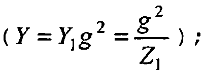
- β is the angle difference between the source impedance ZS and the load impedance ZL (ZL = Z1/g2):

Denoting: ZSY 1 =X

- In the above formulas, ES is the amplitude of the voltage output from the electricity source (ES).
- The critical position of the tap changing device at which the increase of the secondary relative voltage V 1 is equal to the decrease of the primary voltage V is determined by the following formula:

- The value of g which satisfies the above condition is the critical value marked gC . The values of g and gC are calculated by the
calculation unit 5 with the help of the measured values V1 and V and the known values of ES, β and X. If the actual position g of the tap changer is lower then gC , further increase of the tap position, and in consequence increase of the secondary voltage is permitted. Then, the control signal d controls the position of the tap point to increase the secondary voltage V1 if said secondary voltage V1 is lower than a predetermined voltage Vd. To this end, the control unit 7 compares the measured value V1 with the predetermined value Vd. Otherwise the tap changer ought to be blocked. If the tap changer is blocked, and the secondary voltage level is still too low, or decreasing, a first stage of load shedding is executed. - After partial disconnection of the load, the procedure is repeated. The new level of the critical tap changer position is to be determined, what leads to the decision whether the tap changer ought to become unblocked, or not.
- If the tap changer becomes unblocked, and the secondary voltage is too low (i.e. lower than Vth), the tap changer may operate to increase the secondary voltage. After each change of taps it ought to be determined if it was the "total gain" or the "total loss". In case of the "total gain" further operation of the tap changer is accepted, otherwise the tap changer becomes blocked.
- If the tap changer was blocked and the secondary voltage is too low, the next operation of the load shedding is to be initiated, what results in disconnection of a next portion of the transformer load.
- The procedure beginning from the partial disconnection of the load is to be repeated until the critical level of load is reached (established by the system operator).
- In case ZSY1 is unknown, there is another way of checking, whether the last change of the tap changer caused the "net gain" (i.e. increase of the secondary relative voltage is greater than decrease of the primary voltage) or the "net loss". This other way corresponds to a second embodiment of the invention.
Figure 2 shows an apparatus implementing the second embodiment of the invention. - The apparatus according to the second embodiment of the invention comprises a
tap changer 1, acalculator 2, andvoltmeters 3 and 4. Thevoltmeter 3 measures the voltage V1 between the two terminals of the load Z1 and the voltmeter 4 measures the voltage V between the first terminal of the primary winding and the tap point. Thecalculator 2 comprises amemory 8 to store the measured values of voltage V, a calculatingunit 9 and acontrol unit 10. - First, the calculating
unit 9 calculates two quantities, i.e.: - the quantity

- the quantity

- The measured primary voltages VB and VE are stored in the
memory 8 and entered into the calculatingunit 9. The initial and final positions p1 and p2 are output from thetap changer 1 and entered into the calculatingunit 9. - Then, the calculation unit compares


- The step increase of the tap changer was advantageous if:

- If the above condition is satisfied, the last change of taps caused the net gain. Therefore a next step of tap increase is permitted. If (p2-p1)/(1+p2) ≤ (VB-VE)/VB, the tap point is blocked.
- If a next step of tap is permitted, the control signal d controls the position of the tap point to increase the secondary voltage V1 if said secondary voltage is lower then a predetermined value Vd. To this end, the
control unit 10 compares the measured value V1 with the predetermined value Vd. After, the position of the tap point has been modified, new values of (VB-VE)/VB and (p2-p1)/(1+p2) are calculated and compared and the position of the tap point is modified to increase the secondary voltage V1 if (VB-VE)/VB < (p2-p1)/(1+p2), and is blocked if (p2-p1)/(1+p2) ≤ (VB-VE)/VB. - If the tap point has been blocked (p2-p1)/(1+p2) ≤ (VB-VE)/VB), the following steps are implemented:
- measuring a secondary voltage V1s by means of the
voltmeter 3, - comparing the secondary voltage V1s with a threshold value Vth by means of the
control unit 10, and - executing a first load shedding by means of the control signal S output from the
control unit 10 if V1S ≤ Vth. - After the first load shedding has been executed, a new value of (VB-VE)/VB and a new value of (p2-p1)/(1+p2) are calculated and compared. The position of the tap point remains blocked as long as (p2-p1)/(1+p2) ≤ (VB-VE)/VB and is released as soon as (VB-VE)/VB < (p2-p1)/(1+p2).
- The invention presents a new criterion of the tap changing control and a new method of determining the position at which the tap changing device ought to be blocked to avoid unacceptable decrease of the voltage stability margin.
Claims (12)
- Method of adjusting a voltage present across terminals of a load, the load being mounted across terminals of a secondary winding of a transformer (T) comprising a primary winding having a primary voltage (V) between its terminals and a secondary winding having a secondary voltage (V1) between its terminals, the voltage being adjusted by modifying a position of a tap point along the first winding due to the action of a command signal (d) on a tap changer (1) connected to the primary winding, characterized in that said method comprises:- a step of varying the command signal (d) to change the tap point from a first position p1 to a second position p2,- a step of measuring the primary voltage (V) and the secondary voltage (V1) for each first and second position of the tap point,- a step of determining, by means of a computer (2), a relative increase of the secondary voltage and a relative decrease of the primary voltage, and- a calculation step which comprises a step of determining, by means of a computer (2), a relationship which indicates if the relative increase of the secondary voltage is greater than the relative decrease of the primary voltage or not, the position of the tap point being modified to increase the secondary voltage if a relative increase of the secondary voltage is greater than a relative decrease of the primary voltage, and the position of the tap point being blocked or reversed, if not.
- Method of adjusting a voltage present across terminals of a load according to claim 1, wherein the calculation step comprises:- calculating by means of a computer (2):→ a value g of a transformer-turns ratio of the transformer based on the measured primary voltage V and the measured secondary voltage V1 (g=V/V1) for each first and second tap point position, and→ a critical value gc of said transformer-turns ratio which satisfies the condition:

dV/dg being the derivative of the function V(g) and dV1/dg being the derivative of the function V1(g),- comparing g and gc to output a control signal (d) depending on the result of the comparison, and- if gc > g, the control signal controls the position of the tap point to increase the secondary voltage V1 if said secondary voltage is lower than a predetermined value, or- if gc ≤ g, the control signal blocks the position of the tap point. - Method according to claim 2 when gc > g, wherein, after the position of the tap point has been modified to increase the secondary voltage V1, new values of g and gc are calculated and compared to output a new control signal, and:- if gc > g, the new control signal controls the position of the tap point to increase the secondary voltage V1 if said secondary voltage is lower than the predetermined value, or- if gc ≤ g, the new control signal blocks the position of the tap point.
- Method according to claim 2 when gc ≤ g, wherein, after the position of the tap point has been blocked, it further comprises:- measuring a new secondary voltage V1s,- comparing the new secondary voltage V1s with a threshold value Vth, and- executing a first load shedding if V1S ≤ Vth.
- Method according to claim 4 wherein, after the first load shedding has been executed, new values of g and gc are calculated and compared to output a new control signal and:- if gc > g, the new control signal controls the position of the tap point to increase the secondary voltage V1 if said secondary voltage is lower than a predetermined value, or- if gc ≤ g, the position of the tap point remains blocked.
- Method according to claim 5 wherein, if the position of the tap point remains blocked, it further comprises:- measuring a supplementary secondary voltage V1s,- comparing the supplementary secondary voltage V1s with the threshold value Vth, and- executing a supplementary load shedding if V1S ≤ Vth.
- Method according to any claims 2-6, wherein:

 - ZSY 1 = X , with ZS a source impedance of an electricity source connected between a first terminal of the primary winding and the tap point of the primary winding and Y1 the admittance of the load,- ES is the amplitude of the voltage output from the electricity source, and- β is the angle difference between source impedance ZS and load impedance.
 - Method of adjusting a voltage present across terminals of a load according to claim 1, wherein the step of measuring the primary voltage comprises:- measuring a primary voltage VB between a first terminal of the primary winding and the tap point when the tap point has the first position p1, and- measuring a primary voltage VE between the first terminal of the primary winding and the tap point when the tap point has the second position p2,and wherein the calculation step comprises:- calculating, by means of a computer, (VB-VE)/VB and (p2-p1)/(1+p2),- comparing (VB-VE)/VB and (p2-p1)/(1+p2) to output a control signal, and- if (VB-VE)/VB < (p2-p1)/(1+p2), the position of the tap point is modified to increase the secondary voltage if the measured secondary voltage is lower than a predetermined value, and- if (p2-p1)/(1+p2) ≤ (VB-VE)/VB, the position of the tap point is blocked or reversed.
- Method according to claim 8 when (VB-VE)/VB > (p2-p1)/(1+p2), wherein, after the position of the tap point has been modified to increase the secondary voltage V1, new values of (VB-VE)/VB and (p2-p1)/(1+p2) are calculated and compared to output a new control signal and:- if (VB-VE)/VB < (p2-p1)/(1+p2), the new control signal (d) controls the position of the tap point to increase the secondary voltage V1 if said secondary voltage is lower than a predetermined value, or- if (p2-p1)/(1+p2) ≤ (VB-VE)/VB, the new control signal blocks the position of the tap point.
- Method according to claim 8 when (p2-p1)/(1+p2) ≤ (VB-VE)/VB, wherein, after the position of the tap point has been blocked, it further comprises:- measuring a secondary voltage V1S,- comparing the secondary voltage V1S with a threshold value Vth, and- executing a first load shedding if V1S ≤ Vth.
- Method according to claim 10 wherein, after the first load shedding has been executed, new value of (VB-VE)/VB and new value of (p2-p1)/(1+p2) are calculated and compared to output a new control signal depending on the result of the comparison, and- if (VB-VE)/VB < (p2-p1)/(1+p2), the control signal (d) controls the position of the tap point to increase the secondary voltage V1 if said secondary voltage is lower than a predetermined value, or- if (p2-p1)/(1+p2) ≤ (VB-VE)/VB, the position of the tap point remains blocked.
- Method according to claim 11 wherein, if the position of the tap point remains blocked, it further comprises:- measuring a supplementary secondary voltage V1s,- comparing the supplementary secondary voltage V1s with the threshold value Vth, and- executing a supplementary load shedding if V1S ≤ Vth.
Applications Claiming Priority (1)
| Application Number | Priority Date | Filing Date | Title |
|---|---|---|---|
| PCT/EP2009/065314 WO2011060811A1 (en) | 2009-11-17 | 2009-11-17 | Method of adjusting a voltage across terminals of a load |
Publications (2)
| Publication Number | Publication Date |
|---|---|
| EP2502122A1 EP2502122A1 (en) | 2012-09-26 |
| EP2502122B1 true EP2502122B1 (en) | 2014-12-03 |
Family
ID=42341769
Family Applications (1)
| Application Number | Title | Priority Date | Filing Date |
|---|---|---|---|
| EP09752376.5A Not-in-force EP2502122B1 (en) | 2009-11-17 | 2009-11-17 | Method of adjusting a voltage across terminals of a load |
Country Status (3)
| Country | Link |
|---|---|
| EP (1) | EP2502122B1 (en) |
| CN (1) | CN102713782A (en) |
| WO (1) | WO2011060811A1 (en) |
Families Citing this family (2)
| Publication number | Priority date | Publication date | Assignee | Title |
|---|---|---|---|---|
| CN102520748A (en) * | 2011-12-22 | 2012-06-27 | 吉林省电力有限公司松原供电公司 | Power output regulation device and power output regulation method |
| EP2890991A4 (en) * | 2012-08-29 | 2016-05-25 | Megger Sweden Ab | Method and apparatus for measuring load tap changer characteristics |
Family Cites Families (5)
| Publication number | Priority date | Publication date | Assignee | Title |
|---|---|---|---|---|
| US6249719B1 (en) * | 1998-05-15 | 2001-06-19 | Abb Power T&D Company, Inc. | Applications and methods for voltage instability predictor (VIP) |
| US6219591B1 (en) * | 1998-05-15 | 2001-04-17 | Abb Power T&D Company Inc. | Voltage instability predictor (VIP)—method and system for performing adaptive control to improve voltage stability in power systems |
| EP1217709A1 (en) * | 2000-12-22 | 2002-06-26 | ABB Schweiz AG | Method and device for assessing the stability of an electric power transmission network |
| SE0400301D0 (en) * | 2004-02-11 | 2004-02-11 | Stefan Solyom | Power system |
| GB0712749D0 (en) * | 2007-07-02 | 2007-08-08 | Areva T & D Uk Ltd | Method of determining voltage stability margin for load shedding within an electrical power system |
-
2009
- 2009-11-17 WO PCT/EP2009/065314 patent/WO2011060811A1/en not_active Ceased
- 2009-11-17 CN CN2009801633117A patent/CN102713782A/en active Pending
- 2009-11-17 EP EP09752376.5A patent/EP2502122B1/en not_active Not-in-force
Also Published As
| Publication number | Publication date |
|---|---|
| WO2011060811A1 (en) | 2011-05-26 |
| CN102713782A (en) | 2012-10-03 |
| EP2502122A1 (en) | 2012-09-26 |
Similar Documents
| Publication | Publication Date | Title |
|---|---|---|
| CA2636524C (en) | Method of determining voltage stability margin for load shedding within an electrical power system | |
| Wiszniewski | New criteria of voltage stability margin for the purpose of load shedding | |
| US11555837B2 (en) | Volt-var device monitor | |
| US11630145B2 (en) | Intelligent electronic device operation during power swing | |
| EP3069426A1 (en) | Method and apparatus of reactor turn-to-turn protection | |
| US12401187B2 (en) | Detecting an electrical fault within a monitored zone of a power transmission line | |
| EP3389157B1 (en) | Method for improvement of earth-fault protection in compensated mv networks | |
| CN110927516A (en) | Power distribution network single-phase earth fault identification method and system based on grounding transformer tap grounding | |
| CN101432941B (en) | Load compensation in distance protection of three-phase transmission lines | |
| KR102405877B1 (en) | Apparatus and method for detecting secondary failure of MOF | |
| EP2502122A1 (en) | Method of adjusting a voltage across terminals of a load | |
| US20120277929A1 (en) | Method of initiating the load shedding within an electrical power system | |
| KR102237101B1 (en) | Apparatus and method for overvoltage prevention of distribution line connected with distributed power source | |
| CN119335439A (en) | Grounding detection device, method, charging device, storage medium and computer equipment | |
| Ruz et al. | DSTRP: a new algorithm for high impedance fault detection in compensated neutral grounded MV power systems | |
| US20230123385A1 (en) | Power usage in an electricity distribution apparatus for a plurality of electrical loads | |
| EP4492599A1 (en) | Dc fault managed power system | |
| EP4478567A2 (en) | Dc fault managed power system | |
| KR20070094161A (en) | Method for detecting sag and swell using moving average | |
| CN117761579A (en) | Method and voltage monitoring device for detecting line status of electrical equipment | |
| KR20260035419A (en) | Method for detecting islanding operation of a grid-forming inverter through grid-forming inverter and reactive power injection | |
| CN107228998B (en) | Parameter identification-based automatic tracking method for running capacity of magnetic control type parallel reactor | |
| CN119667554A (en) | A transformer winding fault diagnosis test platform and diagnosis method | |
| CN121069272A (en) | Method and system for detecting open triangular winding loop of voltage transformer | |
| CN113589212A (en) | Method for determining saturation point of current transformer based on maximum offset distance method |
Legal Events
| Date | Code | Title | Description |
|---|---|---|---|
| PUAI | Public reference made under article 153(3) epc to a published international application that has entered the european phase |
Free format text: ORIGINAL CODE: 0009012 |
|
| 17P | Request for examination filed |
Effective date: 20120523 |
|
| AK | Designated contracting states |
Kind code of ref document: A1 Designated state(s): AT BE BG CH CY CZ DE DK EE ES FI FR GB GR HR HU IE IS IT LI LT LU LV MC MK MT NL NO PL PT RO SE SI SK SM TR |
|
| DAX | Request for extension of the european patent (deleted) | ||
| REG | Reference to a national code |
Ref country code: DE Ref legal event code: R079 Ref document number: 602009028123 Country of ref document: DE Free format text: PREVIOUS MAIN CLASS: G05F0001140000 Ipc: H02M0005120000 |
|
| RIC1 | Information provided on ipc code assigned before grant |
Ipc: G05F 1/14 20060101ALI20130328BHEP Ipc: H02M 5/12 20060101AFI20130328BHEP |
|
| GRAP | Despatch of communication of intention to grant a patent |
Free format text: ORIGINAL CODE: EPIDOSNIGR1 |
|
| INTG | Intention to grant announced |
Effective date: 20140217 |
|
| GRAP | Despatch of communication of intention to grant a patent |
Free format text: ORIGINAL CODE: EPIDOSNIGR1 |
|
| INTG | Intention to grant announced |
Effective date: 20140627 |
|
| GRAS | Grant fee paid |
Free format text: ORIGINAL CODE: EPIDOSNIGR3 |
|
| GRAA | (expected) grant |
Free format text: ORIGINAL CODE: 0009210 |
|
| AK | Designated contracting states |
Kind code of ref document: B1 Designated state(s): AT BE BG CH CY CZ DE DK EE ES FI FR GB GR HR HU IE IS IT LI LT LU LV MC MK MT NL NO PL PT RO SE SI SK SM TR |
|
| REG | Reference to a national code |
Ref country code: GB Ref legal event code: FG4D |
|
| REG | Reference to a national code |
Ref country code: CH Ref legal event code: NV Representative=s name: BOVARD AG, CH Ref country code: CH Ref legal event code: EP Ref country code: AT Ref legal event code: REF Ref document number: 699869 Country of ref document: AT Kind code of ref document: T Effective date: 20141215 |
|
| REG | Reference to a national code |
Ref country code: IE Ref legal event code: FG4D |
|
| REG | Reference to a national code |
Ref country code: DE Ref legal event code: R096 Ref document number: 602009028123 Country of ref document: DE Effective date: 20150115 |
|
| REG | Reference to a national code |
Ref country code: NL Ref legal event code: VDEP Effective date: 20141203 |
|
| REG | Reference to a national code |
Ref country code: AT Ref legal event code: MK05 Ref document number: 699869 Country of ref document: AT Kind code of ref document: T Effective date: 20141203 |
|
| PG25 | Lapsed in a contracting state [announced via postgrant information from national office to epo] |
Ref country code: NO Free format text: LAPSE BECAUSE OF FAILURE TO SUBMIT A TRANSLATION OF THE DESCRIPTION OR TO PAY THE FEE WITHIN THE PRESCRIBED TIME-LIMIT Effective date: 20150303 Ref country code: LT Free format text: LAPSE BECAUSE OF FAILURE TO SUBMIT A TRANSLATION OF THE DESCRIPTION OR TO PAY THE FEE WITHIN THE PRESCRIBED TIME-LIMIT Effective date: 20141203 Ref country code: ES Free format text: LAPSE BECAUSE OF FAILURE TO SUBMIT A TRANSLATION OF THE DESCRIPTION OR TO PAY THE FEE WITHIN THE PRESCRIBED TIME-LIMIT Effective date: 20141203 Ref country code: FI Free format text: LAPSE BECAUSE OF FAILURE TO SUBMIT A TRANSLATION OF THE DESCRIPTION OR TO PAY THE FEE WITHIN THE PRESCRIBED TIME-LIMIT Effective date: 20141203 Ref country code: NL Free format text: LAPSE BECAUSE OF FAILURE TO SUBMIT A TRANSLATION OF THE DESCRIPTION OR TO PAY THE FEE WITHIN THE PRESCRIBED TIME-LIMIT Effective date: 20141203 |
|
| REG | Reference to a national code |
Ref country code: LT Ref legal event code: MG4D |
|
| PG25 | Lapsed in a contracting state [announced via postgrant information from national office to epo] |
Ref country code: LV Free format text: LAPSE BECAUSE OF FAILURE TO SUBMIT A TRANSLATION OF THE DESCRIPTION OR TO PAY THE FEE WITHIN THE PRESCRIBED TIME-LIMIT Effective date: 20141203 Ref country code: SE Free format text: LAPSE BECAUSE OF FAILURE TO SUBMIT A TRANSLATION OF THE DESCRIPTION OR TO PAY THE FEE WITHIN THE PRESCRIBED TIME-LIMIT Effective date: 20141203 Ref country code: GR Free format text: LAPSE BECAUSE OF FAILURE TO SUBMIT A TRANSLATION OF THE DESCRIPTION OR TO PAY THE FEE WITHIN THE PRESCRIBED TIME-LIMIT Effective date: 20150304 Ref country code: CY Free format text: LAPSE BECAUSE OF FAILURE TO SUBMIT A TRANSLATION OF THE DESCRIPTION OR TO PAY THE FEE WITHIN THE PRESCRIBED TIME-LIMIT Effective date: 20141203 Ref country code: HR Free format text: LAPSE BECAUSE OF FAILURE TO SUBMIT A TRANSLATION OF THE DESCRIPTION OR TO PAY THE FEE WITHIN THE PRESCRIBED TIME-LIMIT Effective date: 20141203 Ref country code: AT Free format text: LAPSE BECAUSE OF FAILURE TO SUBMIT A TRANSLATION OF THE DESCRIPTION OR TO PAY THE FEE WITHIN THE PRESCRIBED TIME-LIMIT Effective date: 20141203 |
|
| PG25 | Lapsed in a contracting state [announced via postgrant information from national office to epo] |
Ref country code: EE Free format text: LAPSE BECAUSE OF FAILURE TO SUBMIT A TRANSLATION OF THE DESCRIPTION OR TO PAY THE FEE WITHIN THE PRESCRIBED TIME-LIMIT Effective date: 20141203 Ref country code: CZ Free format text: LAPSE BECAUSE OF FAILURE TO SUBMIT A TRANSLATION OF THE DESCRIPTION OR TO PAY THE FEE WITHIN THE PRESCRIBED TIME-LIMIT Effective date: 20141203 Ref country code: RO Free format text: LAPSE BECAUSE OF FAILURE TO SUBMIT A TRANSLATION OF THE DESCRIPTION OR TO PAY THE FEE WITHIN THE PRESCRIBED TIME-LIMIT Effective date: 20141203 Ref country code: SK Free format text: LAPSE BECAUSE OF FAILURE TO SUBMIT A TRANSLATION OF THE DESCRIPTION OR TO PAY THE FEE WITHIN THE PRESCRIBED TIME-LIMIT Effective date: 20141203 Ref country code: PT Free format text: LAPSE BECAUSE OF FAILURE TO SUBMIT A TRANSLATION OF THE DESCRIPTION OR TO PAY THE FEE WITHIN THE PRESCRIBED TIME-LIMIT Effective date: 20150403 |
|
| PG25 | Lapsed in a contracting state [announced via postgrant information from national office to epo] |
Ref country code: PL Free format text: LAPSE BECAUSE OF FAILURE TO SUBMIT A TRANSLATION OF THE DESCRIPTION OR TO PAY THE FEE WITHIN THE PRESCRIBED TIME-LIMIT Effective date: 20141203 Ref country code: IS Free format text: LAPSE BECAUSE OF FAILURE TO SUBMIT A TRANSLATION OF THE DESCRIPTION OR TO PAY THE FEE WITHIN THE PRESCRIBED TIME-LIMIT Effective date: 20150403 |
|
| REG | Reference to a national code |
Ref country code: DE Ref legal event code: R097 Ref document number: 602009028123 Country of ref document: DE |
|
| PLBE | No opposition filed within time limit |
Free format text: ORIGINAL CODE: 0009261 |
|
| STAA | Information on the status of an ep patent application or granted ep patent |
Free format text: STATUS: NO OPPOSITION FILED WITHIN TIME LIMIT |
|
| PG25 | Lapsed in a contracting state [announced via postgrant information from national office to epo] |
Ref country code: DK Free format text: LAPSE BECAUSE OF FAILURE TO SUBMIT A TRANSLATION OF THE DESCRIPTION OR TO PAY THE FEE WITHIN THE PRESCRIBED TIME-LIMIT Effective date: 20141203 |
|
| 26N | No opposition filed |
Effective date: 20150904 |
|
| PG25 | Lapsed in a contracting state [announced via postgrant information from national office to epo] |
Ref country code: IT Free format text: LAPSE BECAUSE OF FAILURE TO SUBMIT A TRANSLATION OF THE DESCRIPTION OR TO PAY THE FEE WITHIN THE PRESCRIBED TIME-LIMIT Effective date: 20141203 |
|
| PG25 | Lapsed in a contracting state [announced via postgrant information from national office to epo] |
Ref country code: SI Free format text: LAPSE BECAUSE OF FAILURE TO SUBMIT A TRANSLATION OF THE DESCRIPTION OR TO PAY THE FEE WITHIN THE PRESCRIBED TIME-LIMIT Effective date: 20141203 |
|
| PG25 | Lapsed in a contracting state [announced via postgrant information from national office to epo] |
Ref country code: BE Free format text: LAPSE BECAUSE OF FAILURE TO SUBMIT A TRANSLATION OF THE DESCRIPTION OR TO PAY THE FEE WITHIN THE PRESCRIBED TIME-LIMIT Effective date: 20141203 |
|
| REG | Reference to a national code |
Ref country code: DE Ref legal event code: R119 Ref document number: 602009028123 Country of ref document: DE |
|
| PG25 | Lapsed in a contracting state [announced via postgrant information from national office to epo] |
Ref country code: MC Free format text: LAPSE BECAUSE OF FAILURE TO SUBMIT A TRANSLATION OF THE DESCRIPTION OR TO PAY THE FEE WITHIN THE PRESCRIBED TIME-LIMIT Effective date: 20141203 Ref country code: LU Free format text: LAPSE BECAUSE OF FAILURE TO SUBMIT A TRANSLATION OF THE DESCRIPTION OR TO PAY THE FEE WITHIN THE PRESCRIBED TIME-LIMIT Effective date: 20151117 |
|
| REG | Reference to a national code |
Ref country code: CH Ref legal event code: PL |
|
| GBPC | Gb: european patent ceased through non-payment of renewal fee |
Effective date: 20151117 |
|
| PG25 | Lapsed in a contracting state [announced via postgrant information from national office to epo] |
Ref country code: CH Free format text: LAPSE BECAUSE OF NON-PAYMENT OF DUE FEES Effective date: 20151130 Ref country code: LI Free format text: LAPSE BECAUSE OF NON-PAYMENT OF DUE FEES Effective date: 20151130 |
|
| REG | Reference to a national code |
Ref country code: IE Ref legal event code: MM4A |
|
| REG | Reference to a national code |
Ref country code: FR Ref legal event code: ST Effective date: 20160729 |
|
| PG25 | Lapsed in a contracting state [announced via postgrant information from national office to epo] |
Ref country code: DE Free format text: LAPSE BECAUSE OF NON-PAYMENT OF DUE FEES Effective date: 20160601 Ref country code: IE Free format text: LAPSE BECAUSE OF NON-PAYMENT OF DUE FEES Effective date: 20151117 Ref country code: GB Free format text: LAPSE BECAUSE OF NON-PAYMENT OF DUE FEES Effective date: 20151117 |
|
| PG25 | Lapsed in a contracting state [announced via postgrant information from national office to epo] |
Ref country code: FR Free format text: LAPSE BECAUSE OF NON-PAYMENT OF DUE FEES Effective date: 20151130 |
|
| PG25 | Lapsed in a contracting state [announced via postgrant information from national office to epo] |
Ref country code: BG Free format text: LAPSE BECAUSE OF FAILURE TO SUBMIT A TRANSLATION OF THE DESCRIPTION OR TO PAY THE FEE WITHIN THE PRESCRIBED TIME-LIMIT Effective date: 20141203 Ref country code: SM Free format text: LAPSE BECAUSE OF FAILURE TO SUBMIT A TRANSLATION OF THE DESCRIPTION OR TO PAY THE FEE WITHIN THE PRESCRIBED TIME-LIMIT Effective date: 20141203 Ref country code: HU Free format text: LAPSE BECAUSE OF FAILURE TO SUBMIT A TRANSLATION OF THE DESCRIPTION OR TO PAY THE FEE WITHIN THE PRESCRIBED TIME-LIMIT; INVALID AB INITIO Effective date: 20091117 |
|
| PG25 | Lapsed in a contracting state [announced via postgrant information from national office to epo] |
Ref country code: MT Free format text: LAPSE BECAUSE OF FAILURE TO SUBMIT A TRANSLATION OF THE DESCRIPTION OR TO PAY THE FEE WITHIN THE PRESCRIBED TIME-LIMIT Effective date: 20141203 |
|
| PG25 | Lapsed in a contracting state [announced via postgrant information from national office to epo] |
Ref country code: TR Free format text: LAPSE BECAUSE OF FAILURE TO SUBMIT A TRANSLATION OF THE DESCRIPTION OR TO PAY THE FEE WITHIN THE PRESCRIBED TIME-LIMIT Effective date: 20141203 Ref country code: MK Free format text: LAPSE BECAUSE OF FAILURE TO SUBMIT A TRANSLATION OF THE DESCRIPTION OR TO PAY THE FEE WITHIN THE PRESCRIBED TIME-LIMIT Effective date: 20141203 |