EP2501935B1 - Pump - Google Patents
Pump Download PDFInfo
- Publication number
- EP2501935B1 EP2501935B1 EP10763832.2A EP10763832A EP2501935B1 EP 2501935 B1 EP2501935 B1 EP 2501935B1 EP 10763832 A EP10763832 A EP 10763832A EP 2501935 B1 EP2501935 B1 EP 2501935B1
- Authority
- EP
- European Patent Office
- Prior art keywords
- pump
- flexible membrane
- membrane
- fluid
- recess
- Prior art date
- Legal status (The legal status is an assumption and is not a legal conclusion. Google has not performed a legal analysis and makes no representation as to the accuracy of the status listed.)
- Active
Links
Images


Classifications
-
- F—MECHANICAL ENGINEERING; LIGHTING; HEATING; WEAPONS; BLASTING
- F04—POSITIVE - DISPLACEMENT MACHINES FOR LIQUIDS; PUMPS FOR LIQUIDS OR ELASTIC FLUIDS
- F04B—POSITIVE-DISPLACEMENT MACHINES FOR LIQUIDS; PUMPS
- F04B43/00—Machines, pumps, or pumping installations having flexible working members
- F04B43/02—Machines, pumps, or pumping installations having flexible working members having plate-like flexible members, e.g. diaphragms
- F04B43/06—Pumps having fluid drive
-
- A—HUMAN NECESSITIES
- A61—MEDICAL OR VETERINARY SCIENCE; HYGIENE
- A61M—DEVICES FOR INTRODUCING MEDIA INTO, OR ONTO, THE BODY; DEVICES FOR TRANSDUCING BODY MEDIA OR FOR TAKING MEDIA FROM THE BODY; DEVICES FOR PRODUCING OR ENDING SLEEP OR STUPOR
- A61M1/00—Suction or pumping devices for medical purposes; Devices for carrying-off, for treatment of, or for carrying-over, body-liquids; Drainage systems
- A61M1/36—Other treatment of blood in a by-pass of the natural circulatory system, e.g. temperature adaptation, irradiation ; Extra-corporeal blood circuits
- A61M1/3621—Extra-corporeal blood circuits
- A61M1/3622—Extra-corporeal blood circuits with a cassette forming partially or totally the blood circuit
- A61M1/36225—Extra-corporeal blood circuits with a cassette forming partially or totally the blood circuit with blood pumping means or components thereof
-
- A—HUMAN NECESSITIES
- A61—MEDICAL OR VETERINARY SCIENCE; HYGIENE
- A61M—DEVICES FOR INTRODUCING MEDIA INTO, OR ONTO, THE BODY; DEVICES FOR TRANSDUCING BODY MEDIA OR FOR TAKING MEDIA FROM THE BODY; DEVICES FOR PRODUCING OR ENDING SLEEP OR STUPOR
- A61M1/00—Suction or pumping devices for medical purposes; Devices for carrying-off, for treatment of, or for carrying-over, body-liquids; Drainage systems
- A61M1/36—Other treatment of blood in a by-pass of the natural circulatory system, e.g. temperature adaptation, irradiation ; Extra-corporeal blood circuits
- A61M1/3621—Extra-corporeal blood circuits
- A61M1/3622—Extra-corporeal blood circuits with a cassette forming partially or totally the blood circuit
- A61M1/36226—Constructional details of cassettes, e.g. specific details on material or shape
- A61M1/362261—Constructional details of cassettes, e.g. specific details on material or shape at least one cassette surface or portion thereof being flexible, e.g. the cassette having a rigid base portion with preformed channels and being covered with a foil
-
- A—HUMAN NECESSITIES
- A61—MEDICAL OR VETERINARY SCIENCE; HYGIENE
- A61M—DEVICES FOR INTRODUCING MEDIA INTO, OR ONTO, THE BODY; DEVICES FOR TRANSDUCING BODY MEDIA OR FOR TAKING MEDIA FROM THE BODY; DEVICES FOR PRODUCING OR ENDING SLEEP OR STUPOR
- A61M60/00—Blood pumps; Devices for mechanical circulatory actuation; Balloon pumps for circulatory assistance
- A61M60/10—Location thereof with respect to the patient's body
- A61M60/104—Extracorporeal pumps, i.e. the blood being pumped outside the patient's body
- A61M60/109—Extracorporeal pumps, i.e. the blood being pumped outside the patient's body incorporated within extracorporeal blood circuits or systems
- A61M60/113—Extracorporeal pumps, i.e. the blood being pumped outside the patient's body incorporated within extracorporeal blood circuits or systems in other functional devices, e.g. dialysers or heart-lung machines
-
- A—HUMAN NECESSITIES
- A61—MEDICAL OR VETERINARY SCIENCE; HYGIENE
- A61M—DEVICES FOR INTRODUCING MEDIA INTO, OR ONTO, THE BODY; DEVICES FOR TRANSDUCING BODY MEDIA OR FOR TAKING MEDIA FROM THE BODY; DEVICES FOR PRODUCING OR ENDING SLEEP OR STUPOR
- A61M60/00—Blood pumps; Devices for mechanical circulatory actuation; Balloon pumps for circulatory assistance
- A61M60/30—Medical purposes thereof other than the enhancement of the cardiac output
- A61M60/36—Medical purposes thereof other than the enhancement of the cardiac output for specific blood treatment; for specific therapy
- A61M60/37—Haemodialysis, haemofiltration or diafiltration
-
- A—HUMAN NECESSITIES
- A61—MEDICAL OR VETERINARY SCIENCE; HYGIENE
- A61M—DEVICES FOR INTRODUCING MEDIA INTO, OR ONTO, THE BODY; DEVICES FOR TRANSDUCING BODY MEDIA OR FOR TAKING MEDIA FROM THE BODY; DEVICES FOR PRODUCING OR ENDING SLEEP OR STUPOR
- A61M60/00—Blood pumps; Devices for mechanical circulatory actuation; Balloon pumps for circulatory assistance
- A61M60/40—Details relating to driving
- A61M60/424—Details relating to driving for positive displacement blood pumps
- A61M60/427—Details relating to driving for positive displacement blood pumps the force acting on the blood contacting member being hydraulic or pneumatic
- A61M60/43—Details relating to driving for positive displacement blood pumps the force acting on the blood contacting member being hydraulic or pneumatic using vacuum at the blood pump, e.g. to accelerate filling
-
- A—HUMAN NECESSITIES
- A61—MEDICAL OR VETERINARY SCIENCE; HYGIENE
- A61M—DEVICES FOR INTRODUCING MEDIA INTO, OR ONTO, THE BODY; DEVICES FOR TRANSDUCING BODY MEDIA OR FOR TAKING MEDIA FROM THE BODY; DEVICES FOR PRODUCING OR ENDING SLEEP OR STUPOR
- A61M60/00—Blood pumps; Devices for mechanical circulatory actuation; Balloon pumps for circulatory assistance
- A61M60/80—Constructional details other than related to driving
- A61M60/845—Constructional details other than related to driving of extracorporeal blood pumps
- A61M60/847—Constructional details other than related to driving of extracorporeal blood pumps arranged in a cassette
-
- A—HUMAN NECESSITIES
- A61—MEDICAL OR VETERINARY SCIENCE; HYGIENE
- A61M—DEVICES FOR INTRODUCING MEDIA INTO, OR ONTO, THE BODY; DEVICES FOR TRANSDUCING BODY MEDIA OR FOR TAKING MEDIA FROM THE BODY; DEVICES FOR PRODUCING OR ENDING SLEEP OR STUPOR
- A61M60/00—Blood pumps; Devices for mechanical circulatory actuation; Balloon pumps for circulatory assistance
- A61M60/80—Constructional details other than related to driving
- A61M60/845—Constructional details other than related to driving of extracorporeal blood pumps
- A61M60/849—Disposable parts
-
- A—HUMAN NECESSITIES
- A61—MEDICAL OR VETERINARY SCIENCE; HYGIENE
- A61M—DEVICES FOR INTRODUCING MEDIA INTO, OR ONTO, THE BODY; DEVICES FOR TRANSDUCING BODY MEDIA OR FOR TAKING MEDIA FROM THE BODY; DEVICES FOR PRODUCING OR ENDING SLEEP OR STUPOR
- A61M1/00—Suction or pumping devices for medical purposes; Devices for carrying-off, for treatment of, or for carrying-over, body-liquids; Drainage systems
- A61M1/14—Dialysis systems; Artificial kidneys; Blood oxygenators ; Reciprocating systems for treatment of body fluids, e.g. single needle systems for hemofiltration or pheresis
-
- A—HUMAN NECESSITIES
- A61—MEDICAL OR VETERINARY SCIENCE; HYGIENE
- A61M—DEVICES FOR INTRODUCING MEDIA INTO, OR ONTO, THE BODY; DEVICES FOR TRANSDUCING BODY MEDIA OR FOR TAKING MEDIA FROM THE BODY; DEVICES FOR PRODUCING OR ENDING SLEEP OR STUPOR
- A61M1/00—Suction or pumping devices for medical purposes; Devices for carrying-off, for treatment of, or for carrying-over, body-liquids; Drainage systems
- A61M1/36—Other treatment of blood in a by-pass of the natural circulatory system, e.g. temperature adaptation, irradiation ; Extra-corporeal blood circuits
- A61M1/3621—Extra-corporeal blood circuits
- A61M1/3622—Extra-corporeal blood circuits with a cassette forming partially or totally the blood circuit
- A61M1/36222—Details related to the interface between cassette and machine
Definitions
- the present invention relates to membrane pumps, and in particular, but not exclusively, to a membrane pump for a dialysis machine.
- Membrane pumps are used in a number of medical applications, for example in hemodialysis for the extracorporeal circulation of blood and the preparation and delivery of dialysate to and from the dialyser.
- the membrane covers a dome shaped pump chamber into which the membrane is actuated to draw fluid into, and pump the fluid from, the chamber.
- the sharp angle between the flat portion and the recess can also cause the membrane to fold over the edge leaving a dead spot between the membrane and the recess wall where the membrane has not been actuated sufficiently to touch the chamber wall and expel fluid therebetween. This can lead to pumping inaccuracies and even to blood damage where the blood pools in this area for an unacceptable length of time.
- the dome shaped profile of the pump chamber also presents a number of problems.
- the substantially hemispherical shape means that the membrane descends rapidly into the chamber upon actuation.
- a large volume of fluid is pumped at the beginning of the stroke compared to the end of the stroke.
- the volume of dispensed fluid can be difficult to control on the length of stroke. This can also lead to a hammer action of the pump which can lead to pumping inaccuracies and potential blood damage.
- US 595670 discloses an air driven diaphragm pump.
- EP 0536818 discloses a diaphragm pump.
- US 5458468 discloses a pump has a housing, a base and a flexible diaphragm between the housing and the base. The diaphragm and the base define a driving chamber and the diaphragm and the housing define a pump chamber. The driving chamber is coupled to a pump driver adapted to direct fluid to and from the driving chamber to drive the diaphragm.
- the pump chamber is of generally conical form with its outlet being located at the apex of the conical pump chamber and the inlet being disposed at an angle inclined to the plane of the base of the conical pump chamber and being generally tangential to the outer portion of the base of pump chamber such that flow through the pump chamber is in the form of a continuous spiral vortex.
- US4494912 discloses an air pump having a conical pump chamber and a deformable membrane actuable by fluid or air pressure.
- US 5326234 discloses an air driven fluid pump.
- US 6695593 discloses a fibre optics system for high purity pump diagnostics.
- the membrane descends into the chamber in a more controlled and predictable manner than the prior art pump.
- the displacement of fluid is more evenly distributes through the stroke of the membrane which improves the volumetric performance of the pump.
- a blood pump 2 comprising a disposable pump cartridge 4 comprising a rigid plastic shell 6 having concave recess 8 covered by a flexible membrane 10.
- the recess 8 and the flexible membrane 10 form a pump cavity 12 having an inlet 14 and an outlet 16 leading into and out of the cavity respectively.
- the cartridge 4 abuts a pump driver 18 comprising a platen 20 having a recessed surface 22 therein and a fluid port 24.
- the platen 20 sealingly engages with the cartridge 4 such that the recessed surface 22 and the flexible membrane 10 form a drive chamber 26.
- the fluid port 24 is connectable with a source of positive fluid pressure 28 and a source of negative fluid pressure 30 via a valve 32, controlled by a controller 34 to allow fluid to flow into or out of the drive cavity 26.
- the positive 28 and negative 30 fluid sources are a pressure pump and a vacuum pump respectively.
- the inlet 14 has an inlet valve (not shown) and the outlet 16 has an outlet valve (not shown) associated therewith.
- the inlet valve is closed and the outlet valve is open so the blood within the pump cavity 12 exits the outlet 16 via the outlet valve
- the inlet valve is open and the outlet valve is closed such that blood is drawn into the pump cavity 12 through the inlet 14 via the open inlet valve.
- a blood pump 102 comprising a disposable pump cartridge 114 comprising a rigid plastic shell 116 having conical recess 118 covered by a flexible membrane 110.
- the flexible membrane 110 is attached to a flat upper surface 117 of the rigid shell 116.
- the upper surface 117 takes the form of an annular surface which surrounds the circular profile of the recess 118.
- the recess 118 and the flexible membrane 110 form a pump cavity 112 having an inlet 114 and an outlet 116 leading into and out of the cavity respectively.
- the cartridge 114 abuts a pump driver 118 comprising a platen 120 having a recessed inner surface 122 therein and a fluid port 124.
- the platen 210 sealingly engages with the cartridge 114 such that the inner surface 122 and the flexible membrane 110 form a pump chamber 126.
- the fluid port 124 is connectable with a source of positive fluid pressure 28 and a source of negative fluid pressure 30 via a valve 32, controlled by a controller 34 to allow fluid to flow into or out of the pump chamber 126.
- the membrane 110 is operated in a similar way to the prior art device of Figure 1 .
- the upper surface 117 and inner surface 122 are shown in further detail.
- the upper surface 117 and inner surface 122 are separated by the transition surface 123 which is curve so as to provide a smooth transition of the membrane 110 between the upper and inner surfaces upon actuation.
- the effect of this transition surface is to eliminate the dead spot observed between the membrane 10 and the recessed surface 22 of the prior art pump of Figure 1 as the membrane is able to deflect in a more controlled manner upon actuation.
- the smooth transition of the membrane reduces the stress observed in the membrane 110.
- FIG. 4 shows the pump chamber membrane 110 (not to scale for illustrative purposes) in a series of position of increasing actuation from 110A to 110F. This illustrates the gradual folding of the membrane over the transition surface 123 and the inner surface 122. This provides increased predictability of the pumped volume for a given stroke position, reduces fluid damage and increases the accuracy of the dispensed volume. Additionally the membrane life is improved by a less severe deflection profile, and in particular reduced stress concentration when compared with the part of the prior art membrane situated at the top of the recessed surface 22 of the prior art.
- the pump of the present invention could be used to pump extracorporeal blood, water, partly or fully formed dialysate solution, or other suitable medical liquid used in dialysis or similar medical processes requiring the control of fluid.
Landscapes
- Health & Medical Sciences (AREA)
- Engineering & Computer Science (AREA)
- Heart & Thoracic Surgery (AREA)
- Cardiology (AREA)
- Hematology (AREA)
- Public Health (AREA)
- Anesthesiology (AREA)
- Biomedical Technology (AREA)
- Veterinary Medicine (AREA)
- Life Sciences & Earth Sciences (AREA)
- Animal Behavior & Ethology (AREA)
- General Health & Medical Sciences (AREA)
- Mechanical Engineering (AREA)
- Vascular Medicine (AREA)
- General Engineering & Computer Science (AREA)
- Urology & Nephrology (AREA)
- Pulmonology (AREA)
- External Artificial Organs (AREA)
- Reciprocating Pumps (AREA)
Description
- The present invention relates to membrane pumps, and in particular, but not exclusively, to a membrane pump for a dialysis machine.
- Membrane pumps are used in a number of medical applications, for example in hemodialysis for the extracorporeal circulation of blood and the preparation and delivery of dialysate to and from the dialyser. Commonly, the membrane covers a dome shaped pump chamber into which the membrane is actuated to draw fluid into, and pump the fluid from, the chamber.
- A known pump is described with reference to
Figure 1 below. This form of pump has a number of drawbacks as follows. - The sharp angle between the concave recess of the drive chamber and the flat portion of the pump to which the membrane is attached causes high stresses in the membrane as it folds and stretches over the edge of the flat portion and into the recess upon actuation. This can lead to reduced life of the membrane.
- Furthermore, the sharp angle between the flat portion and the recess can also cause the membrane to fold over the edge leaving a dead spot between the membrane and the recess wall where the membrane has not been actuated sufficiently to touch the chamber wall and expel fluid therebetween. This can lead to pumping inaccuracies and even to blood damage where the blood pools in this area for an unacceptable length of time.
- The dome shaped profile of the pump chamber also presents a number of problems. The substantially hemispherical shape means that the membrane descends rapidly into the chamber upon actuation. Thus a large volume of fluid is pumped at the beginning of the stroke compared to the end of the stroke. Thus the volume of dispensed fluid can be difficult to control on the length of stroke. This can also lead to a hammer action of the pump which can lead to pumping inaccuracies and potential blood damage.
-
US 595670 discloses an air driven diaphragm pump.EP 0536818 discloses a diaphragm pump.US 5458468 discloses a pump has a housing, a base and a flexible diaphragm between the housing and the base. The diaphragm and the base define a driving chamber and the diaphragm and the housing define a pump chamber. The driving chamber is coupled to a pump driver adapted to direct fluid to and from the driving chamber to drive the diaphragm. The pump chamber is of generally conical form with its outlet being located at the apex of the conical pump chamber and the inlet being disposed at an angle inclined to the plane of the base of the conical pump chamber and being generally tangential to the outer portion of the base of pump chamber such that flow through the pump chamber is in the form of a continuous spiral vortex.US4494912 discloses an air pump having a conical pump chamber and a deformable membrane actuable by fluid or air pressure.US 5326234 discloses an air driven fluid pump.US 6695593 discloses a fibre optics system for high purity pump diagnostics. - It is the purpose of the present invention to mitigate at least some of the above problems.
- According to the present invention there is provided a blood pump in accordance with claim 1.
- By providing a conical pump chamber the membrane descends into the chamber in a more controlled and predictable manner than the prior art pump. The displacement of fluid is more evenly distributes through the stroke of the membrane which improves the volumetric performance of the pump.
- The invention will now be described, by way of example only, and with reference to the following drawings, in which:
-
Figure 1 is a representation of a prior art pump; -
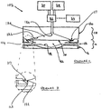
Figure 2 is a representation of a pump according to the present invention; -
Figure 3 is a detailed representation part of the pump ofFigure 2 ; and -
Figure 4 is a representation of the deflection of the membrane within the chamber of the pump ofFigure 2 . - Referring to
Figure 1 ablood pump 2 is shown comprising a disposable pump cartridge 4 comprising a rigid plastic shell 6 having concave recess 8 covered by a flexible membrane 10. The recess 8 and the flexible membrane 10 form a pump cavity 12 having aninlet 14 and anoutlet 16 leading into and out of the cavity respectively. The cartridge 4 abuts apump driver 18 comprising a platen 20 having arecessed surface 22 therein and afluid port 24. In use the platen 20 sealingly engages with the cartridge 4 such that therecessed surface 22 and the flexible membrane 10 form adrive chamber 26. Thefluid port 24 is connectable with a source ofpositive fluid pressure 28 and a source ofnegative fluid pressure 30 via avalve 32, controlled by acontroller 34 to allow fluid to flow into or out of thedrive cavity 26. The positive 28 and negative 30 fluid sources are a pressure pump and a vacuum pump respectively. When thevalve 32 is operated to allow fluid to flow into thedrive chamber 26 from the source ofpositive fluid pressure 28, the membrane 10 is moved towards the recessed surface 8 and any blood that is in the pump cavity 12 is expelled via theoutlet 16. When thevalve 32 is operated to allow fluid to flow out of thedrive chamber 26 to the source ofnegative fluid pressure 30, the membrane 10 is moved away from the recessed surface 8 and towardssurface 22 and blood is drawn into the pump cavity 12 from theinlet 14. - In order to pump blood through the
pump 2 theinlet 14 has an inlet valve (not shown) and theoutlet 16 has an outlet valve (not shown) associated therewith. In operation, when thevalve 32 is operated to allow fluid to flow into thedrive chamber 26 from the source ofpositive fluid pressure 28 the inlet valve is closed and the outlet valve is open so the blood within the pump cavity 12 exits theoutlet 16 via the outlet valve, and when thevalve 32 is operated to allow blood to flow out of thedrive chamber 26 to the source ofnegative fluid pressure 30, the inlet valve is open and the outlet valve is closed such that blood is drawn into the pump cavity 12 through theinlet 14 via the open inlet valve. - Referring to
Figure 2 ablood pump 102 according to the present invention is shown comprising adisposable pump cartridge 114 comprising a rigid plastic shell 116 havingconical recess 118 covered by aflexible membrane 110. Theflexible membrane 110 is attached to a flatupper surface 117 of the rigid shell 116. Theupper surface 117 takes the form of an annular surface which surrounds the circular profile of therecess 118. Therecess 118 and theflexible membrane 110 form apump cavity 112 having aninlet 114 and an outlet 116 leading into and out of the cavity respectively. Thecartridge 114 abuts apump driver 118 comprising a platen 120 having a recessedinner surface 122 therein and afluid port 124. In use the platen 210 sealingly engages with thecartridge 114 such that theinner surface 122 and theflexible membrane 110 form apump chamber 126. Thefluid port 124 is connectable with a source ofpositive fluid pressure 28 and a source ofnegative fluid pressure 30 via avalve 32, controlled by acontroller 34 to allow fluid to flow into or out of thepump chamber 126. Themembrane 110 is operated in a similar way to the prior art device ofFigure 1 . - Referring to
Figure 3 , theupper surface 117 andinner surface 122 are shown in further detail. Theupper surface 117 andinner surface 122 are separated by thetransition surface 123 which is curve so as to provide a smooth transition of themembrane 110 between the upper and inner surfaces upon actuation. The effect of this transition surface is to eliminate the dead spot observed between the membrane 10 and therecessed surface 22 of the prior art pump ofFigure 1 as the membrane is able to deflect in a more controlled manner upon actuation. Furthermore the smooth transition of the membrane reduces the stress observed in themembrane 110. - This process is shown in more detail in
Figure 4 which shows the pump chamber membrane 110 (not to scale for illustrative purposes) in a series of position of increasing actuation from 110A to 110F. This illustrates the gradual folding of the membrane over thetransition surface 123 and theinner surface 122. This provides increased predictability of the pumped volume for a given stroke position, reduces fluid damage and increases the accuracy of the dispensed volume. Additionally the membrane life is improved by a less severe deflection profile, and in particular reduced stress concentration when compared with the part of the prior art membrane situated at the top of therecessed surface 22 of the prior art. - It will be appreciated that the pump of the present invention could be used to pump extracorporeal blood, water, partly or fully formed dialysate solution, or other suitable medical liquid used in dialysis or similar medical processes requiring the control of fluid.
Claims (2)
- A blood pump (102) for a dialysis machine, the blood pump (102) having:a disposable pump cartridge (114) comprising a rigid plastic shell (116) having a conical recess (18);a flexible membrane (110), the flexible membrane (110) being attached to a flat upper surface (117) of the rigid shell (116) to cover the conical recess (18), the upper surface (117) taking the form of an annular surface surrounding the circular profile of the recess (18);the recess (18) and the flexible membrane (110) together defining a pump cavity (112) having an inlet (114) and an outlet (116);wherein, in use the cartridge is arranged to abut a pump driver (118) comprising a platen (120) having a recessed inner surface (122) therein and a fluid port (124),wherein, in use, the platen (210) sealingly engages with the cartridge (114) such that the inner surface (122) and the flexible membrane (110) form a pump chamber (126); andwherein, in use the flexible membrane (110) is actuable between a first position and a second position by fluid pressure to pump a fluid from the pump cavity (112), wherein, in the first position the fluid port (124) of the pump chamber (126) is connected to a source of negative fluid pressure (30) to draw the flexible membrane (110) away from cartridge (114) and against the inner surface (122) of the platen (120), and wherein in the second position the fluid port (124) of the pump chamber (126) is connected to a source of positive fluid pressure (28) to extend the flexible membrane (110) into the pump cavity (112) against the recess (118); andwherein arranged between the flat upper surface (117) and the conical recess (118) is a transition surface (123) which has a curved profile adapted to provide a smooth transition of the flexible membrane (110) within the pump cavity (112) upon actuation of the pump.
- The blood pump (102) of claim 1 wherein the pump cavity (112) is frustoconical.
Applications Claiming Priority (2)
| Application Number | Priority Date | Filing Date | Title |
|---|---|---|---|
| GBGB0915327.1A GB0915327D0 (en) | 2009-09-03 | 2009-09-03 | Pump |
| PCT/GB2010/001667 WO2011027118A1 (en) | 2009-09-03 | 2010-09-03 | Pump |
Publications (2)
| Publication Number | Publication Date |
|---|---|
| EP2501935A1 EP2501935A1 (en) | 2012-09-26 |
| EP2501935B1 true EP2501935B1 (en) | 2019-04-10 |
Family
ID=41203084
Family Applications (1)
| Application Number | Title | Priority Date | Filing Date |
|---|---|---|---|
| EP10763832.2A Active EP2501935B1 (en) | 2009-09-03 | 2010-09-03 | Pump |
Country Status (4)
| Country | Link |
|---|---|
| US (1) | US9482218B2 (en) |
| EP (1) | EP2501935B1 (en) |
| GB (1) | GB0915327D0 (en) |
| WO (1) | WO2011027118A1 (en) |
Families Citing this family (22)
| Publication number | Priority date | Publication date | Assignee | Title |
|---|---|---|---|---|
| US10089443B2 (en) | 2012-05-15 | 2018-10-02 | Baxter International Inc. | Home medical device systems and methods for therapy prescription and tracking, servicing and inventory |
| US8501009B2 (en) | 2010-06-07 | 2013-08-06 | State Of Oregon Acting By And Through The State Board Of Higher Education On Behalf Of Oregon State University | Fluid purification system |
| GB201201330D0 (en) * | 2012-01-26 | 2012-03-14 | Quanta Fluid Solutions Ltd | Dialysis machine |
| CN104254352B (en) * | 2012-02-16 | 2016-12-14 | 宽塔流体解决方案有限公司 | Blood pump |
| GB201305755D0 (en) | 2013-03-28 | 2013-05-15 | Quanta Fluid Solutions Ltd | Re-Use of a Hemodialysis Cartridge |
| GB201305758D0 (en) * | 2013-03-28 | 2013-05-15 | Quanta Fluid Solutions Ltd | Blood Pump |
| GB201314512D0 (en) | 2013-08-14 | 2013-09-25 | Quanta Fluid Solutions Ltd | Dual Haemodialysis and Haemodiafiltration blood treatment device |
| EP3838308A1 (en) | 2014-04-29 | 2021-06-23 | Outset Medical, Inc. | Dialysis system and methods |
| GB201409796D0 (en) | 2014-06-02 | 2014-07-16 | Quanta Fluid Solutions Ltd | Method of heat sanitization of a haemodialysis water circuit using a calculated dose |
| US10697447B2 (en) * | 2014-08-21 | 2020-06-30 | Fenwal, Inc. | Magnet-based systems and methods for transferring fluid |
| GB2544514B (en) * | 2015-11-19 | 2020-12-16 | Quanta Dialysis Technologies Ltd | Dialysis machine with valve clamp arrangement |
| GB201523104D0 (en) | 2015-12-30 | 2016-02-10 | Quanta Fluid Solutions Ltd | Dialysis machine |
| GB2547214A (en) | 2016-02-10 | 2017-08-16 | Quanta Fluid Solutions Ltd | Membrane pump usage condition detection |
| ES2908601T3 (en) | 2016-08-19 | 2022-05-03 | Outset Medical Inc | Peritoneal dialysis system and methods |
| GB201622119D0 (en) | 2016-12-23 | 2017-02-08 | Quanta Dialysis Tech Ltd | Improved valve leak detection system |
| GB201701740D0 (en) | 2017-02-02 | 2017-03-22 | Quanta Dialysis Tech Ltd | Phased convective operation |
| GB201705273D0 (en) | 2017-03-31 | 2017-05-17 | Quanta Dialysis Tech Ltd | Data storage amd exchange by medical device components |
| GB201710546D0 (en) | 2017-06-30 | 2017-08-16 | Quanta Dialysis Tech Ltd | Dialysis systems, devices and methods |
| USD907211S1 (en) | 2017-09-28 | 2021-01-05 | Quanta Dialysis Technologies Ltd. | Dialysis machine |
| JP2021533881A (en) | 2018-08-23 | 2021-12-09 | アウトセット・メディカル・インコーポレイテッドOutset Medical, Inc. | Dialysis system and method |
| BR112021021836A2 (en) | 2019-04-30 | 2022-01-04 | Outset Medical Inc | Methods for calculating blood pressure, for creating dialysate in a dialysis system, for measuring the percentage of rejection in a dialysis system, for collecting and analyzing blood plasma, for removing gas from an extracorporeal circuit of a dialysis system, for inferring a line pressure in an extracorporeal circuit of a dialysis system, to provide extracorporeal and intracorporeal dialysis therapy, to mount a cartridge-style patient tube set in a dialysis machine, and to prepare a dialysis machine for dialysis therapy , air removal and flow chambers, dialysis system, dialysate dispensing subsystem, single-use microbe/endotoxin filter, dialyzer, device for measuring pressure from a dialysis system, and blood tube set |
| GB2584335A (en) | 2019-05-31 | 2020-12-02 | Quanta Dialysis Technologies Ltd | Source container connector |
Citations (2)
| Publication number | Priority date | Publication date | Assignee | Title |
|---|---|---|---|---|
| US5326234A (en) * | 1993-02-17 | 1994-07-05 | Versa-Matic Tool, Inc. | Fluid driven pump |
| US6695593B1 (en) * | 1998-10-05 | 2004-02-24 | Trebor International, Inc. | Fiber optics systems for high purity pump diagnostics |
Family Cites Families (20)
| Publication number | Priority date | Publication date | Assignee | Title |
|---|---|---|---|---|
| US3338171A (en) * | 1965-09-15 | 1967-08-29 | Du Pont | Pneumatically operable diaphragm pumps |
| US3468261A (en) * | 1967-01-23 | 1969-09-23 | Altec Ges Fur Allg Landtechnik | Pump |
| US3606592A (en) * | 1970-05-20 | 1971-09-20 | Bendix Corp | Fluid pump |
| DE2116456A1 (en) * | 1971-04-03 | 1972-10-12 | Pumpenfabrik Urach, 7417 Urach | Diaphragm pump for conveying liquid or gaseous media |
| DE2950381A1 (en) * | 1979-12-14 | 1981-06-19 | Boehringer Mannheim Gmbh, 6800 Mannheim | METHOD AND REAGENT FOR DETERMINING TRIGLYCERIDES |
| ATE10670T1 (en) * | 1980-12-29 | 1984-12-15 | Lewa Herbert Ott Gmbh + Co. | DIAPHRAGM PUMP WITH RELIEVED CLAMPED DIAPHRAGM. |
| US4494912A (en) * | 1982-09-16 | 1985-01-22 | Pauliukonis Richard S | Energy conserving air pump |
| JP2975105B2 (en) | 1988-12-29 | 1999-11-10 | アン・ルイス・チヤング | Diaphragm pump |
| IT1251398B (en) | 1991-09-06 | 1995-05-09 | Nuovopignone Ind Meccaniche Ef | PERFECTED MEMBRANE PUMP, PARTICULARLY SUITABLE FOR FLUIDS CONTAINING GAS. |
| US5476368A (en) * | 1992-08-20 | 1995-12-19 | Ryder International Corporation | Sterile fluid pump diaphragm construction |
| US5385540A (en) * | 1993-05-26 | 1995-01-31 | Quest Medical, Inc. | Cardioplegia delivery system |
| US5957670A (en) | 1997-08-26 | 1999-09-28 | Wilden Pump & Engineering Co. | Air driven diaphragm pump |
| US6497676B1 (en) * | 2000-02-10 | 2002-12-24 | Baxter International | Method and apparatus for monitoring and controlling peritoneal dialysis therapy |
| DE10012904B4 (en) * | 2000-03-16 | 2004-08-12 | Lewa Herbert Ott Gmbh + Co | Membrane clamping with elasticity compensation |
| WO2002081917A1 (en) | 2001-04-09 | 2002-10-17 | Pumping Systems Technologies Pty Limited | Displacement pump and ancillary equipment |
| DE10216146A1 (en) * | 2002-04-12 | 2003-10-30 | Bayer Ag | diaphragm pump |
| US6814547B2 (en) * | 2002-05-24 | 2004-11-09 | Baxter International Inc. | Medical fluid pump |
| US7153286B2 (en) * | 2002-05-24 | 2006-12-26 | Baxter International Inc. | Automated dialysis system |
| US7238164B2 (en) * | 2002-07-19 | 2007-07-03 | Baxter International Inc. | Systems, methods and apparatuses for pumping cassette-based therapies |
| US8038639B2 (en) * | 2004-11-04 | 2011-10-18 | Baxter International Inc. | Medical fluid system with flexible sheeting disposable unit |
-
2009
- 2009-09-03 GB GBGB0915327.1A patent/GB0915327D0/en not_active Ceased
-
2010
- 2010-09-03 WO PCT/GB2010/001667 patent/WO2011027118A1/en not_active Ceased
- 2010-09-03 US US13/394,166 patent/US9482218B2/en active Active
- 2010-09-03 EP EP10763832.2A patent/EP2501935B1/en active Active
Patent Citations (2)
| Publication number | Priority date | Publication date | Assignee | Title |
|---|---|---|---|---|
| US5326234A (en) * | 1993-02-17 | 1994-07-05 | Versa-Matic Tool, Inc. | Fluid driven pump |
| US6695593B1 (en) * | 1998-10-05 | 2004-02-24 | Trebor International, Inc. | Fiber optics systems for high purity pump diagnostics |
Also Published As
| Publication number | Publication date |
|---|---|
| US20120275943A1 (en) | 2012-11-01 |
| EP2501935A1 (en) | 2012-09-26 |
| WO2011027118A1 (en) | 2011-03-10 |
| GB0915327D0 (en) | 2009-10-07 |
| US9482218B2 (en) | 2016-11-01 |
Similar Documents
| Publication | Publication Date | Title |
|---|---|---|
| US9482218B2 (en) | Deformable membrane pump for dialysis machine | |
| EP2180911B1 (en) | Fluid pump with disposable component | |
| EP1099854B1 (en) | Peristaltic pump and cassette | |
| US9220825B2 (en) | Blood pump | |
| CN110088472B (en) | Volumetric pump for medical liquids, blood treatment device and method for controlling same | |
| EP2268338B1 (en) | Blood treatment apparatus | |
| EP3628366A1 (en) | Tube for extra-corporeal circuit | |
| AU616586B2 (en) | Apparatus for processing fluid and method of driving the same | |
| CN104204517B (en) | Reciprocating pump, for supplying by means of reciprocating pump and measuring the device of the fluid for medical object | |
| US4515591A (en) | Disposable syringe cartridge for fluid delivery apparatus | |
| EP2978464B1 (en) | Blood pump | |
| CN104906643A (en) | Blood pumping device | |
| JP2013137034A (en) | System and pump apparatus for processing fluid sample | |
| EP2978466B1 (en) | Blood pump | |
| JP2019068950A (en) | Container for pressure measurement and blood purifier | |
| CN111594420A (en) | Diaphragm pump with suction and lift | |
| US20140213993A1 (en) | Ophthalmic surgical cassette | |
| CN111375095A (en) | Damper using balloon as port for reciprocating pump | |
| CN111379694A (en) | Using Silicone O-Rings in Double-Acting Flushing Pumps | |
| CN214232240U (en) | Syringe and barrel | |
| CN120285431A (en) | A ventricular assist system | |
| CN121910967A (en) | Liquid level detection balancing unit for hemodialysis | |
| CN109821093A (en) | A piezoelectric stack-driven infusion device | |
| CN109185124A (en) | A kind of integrated gear pump | |
| KR20130078155A (en) | Pulsebeat type blood-pump capable of cardiac output adjustment |
Legal Events
| Date | Code | Title | Description |
|---|---|---|---|
| PUAI | Public reference made under article 153(3) epc to a published international application that has entered the european phase |
Free format text: ORIGINAL CODE: 0009012 |
|
| 17P | Request for examination filed |
Effective date: 20120406 |
|
| AK | Designated contracting states |
Kind code of ref document: A1 Designated state(s): AL AT BE BG CH CY CZ DE DK EE ES FI FR GB GR HR HU IE IS IT LI LT LU LV MC MK MT NL NO PL PT RO SE SI SK SM TR |
|
| DAX | Request for extension of the european patent (deleted) | ||
| 17Q | First examination report despatched |
Effective date: 20130503 |
|
| RIN1 | Information on inventor provided before grant (corrected) |
Inventor name: COATES, JAMES Inventor name: BUCKBERRY, CLIVE Inventor name: WALLACE, MARK |
|
| STAA | Information on the status of an ep patent application or granted ep patent |
Free format text: STATUS: EXAMINATION IS IN PROGRESS |
|
| GRAP | Despatch of communication of intention to grant a patent |
Free format text: ORIGINAL CODE: EPIDOSNIGR1 |
|
| STAA | Information on the status of an ep patent application or granted ep patent |
Free format text: STATUS: GRANT OF PATENT IS INTENDED |
|
| RIC1 | Information provided on ipc code assigned before grant |
Ipc: A61M 1/10 20060101ALI20180928BHEP Ipc: F04B 43/06 20060101AFI20180928BHEP Ipc: A61M 1/14 20060101ALI20180928BHEP |
|
| INTG | Intention to grant announced |
Effective date: 20181017 |
|
| RIN1 | Information on inventor provided before grant (corrected) |
Inventor name: COATES, JAMES Inventor name: BUCKBERRY, CLIVE Inventor name: WALLACE, MARK |
|
| RAP1 | Party data changed (applicant data changed or rights of an application transferred) |
Owner name: QUANTA DIALYSIS TECHNOLOGIES LIMITED |
|
| GRAS | Grant fee paid |
Free format text: ORIGINAL CODE: EPIDOSNIGR3 |
|
| GRAA | (expected) grant |
Free format text: ORIGINAL CODE: 0009210 |
|
| STAA | Information on the status of an ep patent application or granted ep patent |
Free format text: STATUS: THE PATENT HAS BEEN GRANTED |
|
| AK | Designated contracting states |
Kind code of ref document: B1 Designated state(s): AL AT BE BG CH CY CZ DE DK EE ES FI FR GB GR HR HU IE IS IT LI LT LU LV MC MK MT NL NO PL PT RO SE SI SK SM TR |
|
| REG | Reference to a national code |
Ref country code: GB Ref legal event code: FG4D |
|
| REG | Reference to a national code |
Ref country code: CH Ref legal event code: EP Ref country code: AT Ref legal event code: REF Ref document number: 1119027 Country of ref document: AT Kind code of ref document: T Effective date: 20190415 |
|
| REG | Reference to a national code |
Ref country code: IE Ref legal event code: FG4D |
|
| REG | Reference to a national code |
Ref country code: DE Ref legal event code: R096 Ref document number: 602010058164 Country of ref document: DE |
|
| REG | Reference to a national code |
Ref country code: SE Ref legal event code: TRGR |
|
| REG | Reference to a national code |
Ref country code: NL Ref legal event code: FP |
|
| REG | Reference to a national code |
Ref country code: LT Ref legal event code: MG4D |
|
| REG | Reference to a national code |
Ref country code: AT Ref legal event code: MK05 Ref document number: 1119027 Country of ref document: AT Kind code of ref document: T Effective date: 20190410 |
|
| PG25 | Lapsed in a contracting state [announced via postgrant information from national office to epo] |
Ref country code: FI Free format text: LAPSE BECAUSE OF FAILURE TO SUBMIT A TRANSLATION OF THE DESCRIPTION OR TO PAY THE FEE WITHIN THE PRESCRIBED TIME-LIMIT Effective date: 20190410 Ref country code: NO Free format text: LAPSE BECAUSE OF FAILURE TO SUBMIT A TRANSLATION OF THE DESCRIPTION OR TO PAY THE FEE WITHIN THE PRESCRIBED TIME-LIMIT Effective date: 20190710 Ref country code: LT Free format text: LAPSE BECAUSE OF FAILURE TO SUBMIT A TRANSLATION OF THE DESCRIPTION OR TO PAY THE FEE WITHIN THE PRESCRIBED TIME-LIMIT Effective date: 20190410 Ref country code: ES Free format text: LAPSE BECAUSE OF FAILURE TO SUBMIT A TRANSLATION OF THE DESCRIPTION OR TO PAY THE FEE WITHIN THE PRESCRIBED TIME-LIMIT Effective date: 20190410 Ref country code: AL Free format text: LAPSE BECAUSE OF FAILURE TO SUBMIT A TRANSLATION OF THE DESCRIPTION OR TO PAY THE FEE WITHIN THE PRESCRIBED TIME-LIMIT Effective date: 20190410 Ref country code: HR Free format text: LAPSE BECAUSE OF FAILURE TO SUBMIT A TRANSLATION OF THE DESCRIPTION OR TO PAY THE FEE WITHIN THE PRESCRIBED TIME-LIMIT Effective date: 20190410 Ref country code: PT Free format text: LAPSE BECAUSE OF FAILURE TO SUBMIT A TRANSLATION OF THE DESCRIPTION OR TO PAY THE FEE WITHIN THE PRESCRIBED TIME-LIMIT Effective date: 20190910 |
|
| PG25 | Lapsed in a contracting state [announced via postgrant information from national office to epo] |
Ref country code: PL Free format text: LAPSE BECAUSE OF FAILURE TO SUBMIT A TRANSLATION OF THE DESCRIPTION OR TO PAY THE FEE WITHIN THE PRESCRIBED TIME-LIMIT Effective date: 20190410 Ref country code: LV Free format text: LAPSE BECAUSE OF FAILURE TO SUBMIT A TRANSLATION OF THE DESCRIPTION OR TO PAY THE FEE WITHIN THE PRESCRIBED TIME-LIMIT Effective date: 20190410 Ref country code: GR Free format text: LAPSE BECAUSE OF FAILURE TO SUBMIT A TRANSLATION OF THE DESCRIPTION OR TO PAY THE FEE WITHIN THE PRESCRIBED TIME-LIMIT Effective date: 20190711 Ref country code: BG Free format text: LAPSE BECAUSE OF FAILURE TO SUBMIT A TRANSLATION OF THE DESCRIPTION OR TO PAY THE FEE WITHIN THE PRESCRIBED TIME-LIMIT Effective date: 20190710 |
|
| PG25 | Lapsed in a contracting state [announced via postgrant information from national office to epo] |
Ref country code: AT Free format text: LAPSE BECAUSE OF FAILURE TO SUBMIT A TRANSLATION OF THE DESCRIPTION OR TO PAY THE FEE WITHIN THE PRESCRIBED TIME-LIMIT Effective date: 20190410 Ref country code: IS Free format text: LAPSE BECAUSE OF FAILURE TO SUBMIT A TRANSLATION OF THE DESCRIPTION OR TO PAY THE FEE WITHIN THE PRESCRIBED TIME-LIMIT Effective date: 20190810 |
|
| REG | Reference to a national code |
Ref country code: DE Ref legal event code: R097 Ref document number: 602010058164 Country of ref document: DE |
|
| PG25 | Lapsed in a contracting state [announced via postgrant information from national office to epo] |
Ref country code: SK Free format text: LAPSE BECAUSE OF FAILURE TO SUBMIT A TRANSLATION OF THE DESCRIPTION OR TO PAY THE FEE WITHIN THE PRESCRIBED TIME-LIMIT Effective date: 20190410 Ref country code: EE Free format text: LAPSE BECAUSE OF FAILURE TO SUBMIT A TRANSLATION OF THE DESCRIPTION OR TO PAY THE FEE WITHIN THE PRESCRIBED TIME-LIMIT Effective date: 20190410 Ref country code: CZ Free format text: LAPSE BECAUSE OF FAILURE TO SUBMIT A TRANSLATION OF THE DESCRIPTION OR TO PAY THE FEE WITHIN THE PRESCRIBED TIME-LIMIT Effective date: 20190410 Ref country code: RO Free format text: LAPSE BECAUSE OF FAILURE TO SUBMIT A TRANSLATION OF THE DESCRIPTION OR TO PAY THE FEE WITHIN THE PRESCRIBED TIME-LIMIT Effective date: 20190410 Ref country code: DK Free format text: LAPSE BECAUSE OF FAILURE TO SUBMIT A TRANSLATION OF THE DESCRIPTION OR TO PAY THE FEE WITHIN THE PRESCRIBED TIME-LIMIT Effective date: 20190410 |
|
| PLBE | No opposition filed within time limit |
Free format text: ORIGINAL CODE: 0009261 |
|
| STAA | Information on the status of an ep patent application or granted ep patent |
Free format text: STATUS: NO OPPOSITION FILED WITHIN TIME LIMIT |
|
| PG25 | Lapsed in a contracting state [announced via postgrant information from national office to epo] |
Ref country code: IT Free format text: LAPSE BECAUSE OF FAILURE TO SUBMIT A TRANSLATION OF THE DESCRIPTION OR TO PAY THE FEE WITHIN THE PRESCRIBED TIME-LIMIT Effective date: 20190410 Ref country code: SM Free format text: LAPSE BECAUSE OF FAILURE TO SUBMIT A TRANSLATION OF THE DESCRIPTION OR TO PAY THE FEE WITHIN THE PRESCRIBED TIME-LIMIT Effective date: 20190410 |
|
| 26N | No opposition filed |
Effective date: 20200113 |
|
| PG25 | Lapsed in a contracting state [announced via postgrant information from national office to epo] |
Ref country code: TR Free format text: LAPSE BECAUSE OF FAILURE TO SUBMIT A TRANSLATION OF THE DESCRIPTION OR TO PAY THE FEE WITHIN THE PRESCRIBED TIME-LIMIT Effective date: 20190410 |
|
| PG25 | Lapsed in a contracting state [announced via postgrant information from national office to epo] |
Ref country code: SI Free format text: LAPSE BECAUSE OF FAILURE TO SUBMIT A TRANSLATION OF THE DESCRIPTION OR TO PAY THE FEE WITHIN THE PRESCRIBED TIME-LIMIT Effective date: 20190410 Ref country code: MC Free format text: LAPSE BECAUSE OF FAILURE TO SUBMIT A TRANSLATION OF THE DESCRIPTION OR TO PAY THE FEE WITHIN THE PRESCRIBED TIME-LIMIT Effective date: 20190410 |
|
| REG | Reference to a national code |
Ref country code: CH Ref legal event code: PL |
|
| PG25 | Lapsed in a contracting state [announced via postgrant information from national office to epo] |
Ref country code: LU Free format text: LAPSE BECAUSE OF NON-PAYMENT OF DUE FEES Effective date: 20190903 Ref country code: IE Free format text: LAPSE BECAUSE OF NON-PAYMENT OF DUE FEES Effective date: 20190903 Ref country code: CH Free format text: LAPSE BECAUSE OF NON-PAYMENT OF DUE FEES Effective date: 20190930 Ref country code: LI Free format text: LAPSE BECAUSE OF NON-PAYMENT OF DUE FEES Effective date: 20190930 |
|
| REG | Reference to a national code |
Ref country code: BE Ref legal event code: MM Effective date: 20190930 |
|
| PG25 | Lapsed in a contracting state [announced via postgrant information from national office to epo] |
Ref country code: BE Free format text: LAPSE BECAUSE OF NON-PAYMENT OF DUE FEES Effective date: 20190930 |
|
| PG25 | Lapsed in a contracting state [announced via postgrant information from national office to epo] |
Ref country code: CY Free format text: LAPSE BECAUSE OF FAILURE TO SUBMIT A TRANSLATION OF THE DESCRIPTION OR TO PAY THE FEE WITHIN THE PRESCRIBED TIME-LIMIT Effective date: 20190410 |
|
| PG25 | Lapsed in a contracting state [announced via postgrant information from national office to epo] |
Ref country code: MT Free format text: LAPSE BECAUSE OF FAILURE TO SUBMIT A TRANSLATION OF THE DESCRIPTION OR TO PAY THE FEE WITHIN THE PRESCRIBED TIME-LIMIT Effective date: 20190410 Ref country code: HU Free format text: LAPSE BECAUSE OF FAILURE TO SUBMIT A TRANSLATION OF THE DESCRIPTION OR TO PAY THE FEE WITHIN THE PRESCRIBED TIME-LIMIT; INVALID AB INITIO Effective date: 20100903 |
|
| PG25 | Lapsed in a contracting state [announced via postgrant information from national office to epo] |
Ref country code: MK Free format text: LAPSE BECAUSE OF FAILURE TO SUBMIT A TRANSLATION OF THE DESCRIPTION OR TO PAY THE FEE WITHIN THE PRESCRIBED TIME-LIMIT Effective date: 20190410 |
|
| PGFP | Annual fee paid to national office [announced via postgrant information from national office to epo] |
Ref country code: SE Payment date: 20230921 Year of fee payment: 14 |
|
| REG | Reference to a national code |
Ref country code: SE Ref legal event code: EUG |
|
| PGFP | Annual fee paid to national office [announced via postgrant information from national office to epo] |
Ref country code: DE Payment date: 20250919 Year of fee payment: 16 |
|
| PG25 | Lapsed in a contracting state [announced via postgrant information from national office to epo] |
Ref country code: SE Free format text: LAPSE BECAUSE OF NON-PAYMENT OF DUE FEES Effective date: 20240904 |
|
| PGFP | Annual fee paid to national office [announced via postgrant information from national office to epo] |
Ref country code: NL Payment date: 20250918 Year of fee payment: 16 |
|
| PGFP | Annual fee paid to national office [announced via postgrant information from national office to epo] |
Ref country code: GB Payment date: 20250917 Year of fee payment: 16 |
|
| PGFP | Annual fee paid to national office [announced via postgrant information from national office to epo] |
Ref country code: FR Payment date: 20250922 Year of fee payment: 16 |