EP2501579B1 - Energy storage system including pressurized reservoir - Google Patents
Energy storage system including pressurized reservoir Download PDFInfo
- Publication number
- EP2501579B1 EP2501579B1 EP10782502.8A EP10782502A EP2501579B1 EP 2501579 B1 EP2501579 B1 EP 2501579B1 EP 10782502 A EP10782502 A EP 10782502A EP 2501579 B1 EP2501579 B1 EP 2501579B1
- Authority
- EP
- European Patent Office
- Prior art keywords
- bladder
- interior chamber
- working fluid
- motor
- pump
- Prior art date
- Legal status (The legal status is an assumption and is not a legal conclusion. Google has not performed a legal analysis and makes no representation as to the accuracy of the status listed.)
- Not-in-force
Links
Images

Classifications
-
- B—PERFORMING OPERATIONS; TRANSPORTING
- B60—VEHICLES IN GENERAL
- B60K—ARRANGEMENT OR MOUNTING OF PROPULSION UNITS OR OF TRANSMISSIONS IN VEHICLES; ARRANGEMENT OR MOUNTING OF PLURAL DIVERSE PRIME-MOVERS IN VEHICLES; AUXILIARY DRIVES FOR VEHICLES; INSTRUMENTATION OR DASHBOARDS FOR VEHICLES; ARRANGEMENTS IN CONNECTION WITH COOLING, AIR INTAKE, GAS EXHAUST OR FUEL SUPPLY OF PROPULSION UNITS IN VEHICLES
- B60K6/00—Arrangement or mounting of plural diverse prime-movers for mutual or common propulsion, e.g. hybrid propulsion systems comprising electric motors and internal combustion engines
- B60K6/08—Prime-movers comprising combustion engines and mechanical or fluid energy storing means
- B60K6/12—Prime-movers comprising combustion engines and mechanical or fluid energy storing means by means of a chargeable fluidic accumulator
-
- Y—GENERAL TAGGING OF NEW TECHNOLOGICAL DEVELOPMENTS; GENERAL TAGGING OF CROSS-SECTIONAL TECHNOLOGIES SPANNING OVER SEVERAL SECTIONS OF THE IPC; TECHNICAL SUBJECTS COVERED BY FORMER USPC CROSS-REFERENCE ART COLLECTIONS [XRACs] AND DIGESTS
- Y02—TECHNOLOGIES OR APPLICATIONS FOR MITIGATION OR ADAPTATION AGAINST CLIMATE CHANGE
- Y02T—CLIMATE CHANGE MITIGATION TECHNOLOGIES RELATED TO TRANSPORTATION
- Y02T10/00—Road transport of goods or passengers
- Y02T10/60—Other road transportation technologies with climate change mitigation effect
- Y02T10/62—Hybrid vehicles
Definitions
- the present invention relates to hybrid drive systems for vehicles and more particularly to hybrid hydraulic drive systems for vehicles.
- a typical vehicle hybrid hydraulic drive system uses a reversible pump/motor to absorb power from and add power to or assist a conventional vehicle drive system.
- the system absorbs power by pumping hydraulic fluid from a low pressure reservoir into a hydraulic energy storage system.
- This hydraulic energy storage system typically includes one or more nitrogen-charged hydraulic accumulators.
- Hybrid hydraulic drive systems typically add power to conventional vehicle drive systems by utilizing the hydraulic energy stored in the hydraulic accumulators to drive the reversible pump/motor as a motor.
- the present invention provides, in one aspect, an energy storage system including a reservoir defining an interior chamber, a collapsible bladder positioned within the interior chamber and having working fluid therein, a one-way valve in fluid communication with the interior chamber and operable to permit entry of replacement air into the interior chamber as working fluid exits the bladder, a reversible pump/motor in fluid communication with the bladder, and an accumulator containing working fluid and gas.
- the accumulator is in selective fluid communication with the reversible pump/motor to deliver pressurized working fluid to the reversible pump/motor when operating as a motor, and to receive pressurized working fluid discharged by the reversible pump/motor when operating as a pump.
- the present invention provides, in another aspect, a method of operating an energy storage system.
- the method includes providing a reservoir defining an interior chamber, positioning a collapsible bladder within the interior chamber, returning working fluid to the collapsible bladder with a reversible pump/motor when operating as a motor, drawing working fluid from the collapsible bladder when the reversible pump/motor is operating as a pump, and permitting replacement air to enter the interior chamber of the reservoir when working fluid is drawn from the collapsible bladder.
- the reversible pump/motor 22 is drivably coupled to a rotating shaft 26 (e.g., an output shaft of an engine, an accessory drive system of the engine, a drive shaft between a transmission and an axle assembly, etc.).
- a rotating shaft 26 e.g., an output shaft of an engine, an accessory drive system of the engine, a drive shaft between a transmission and an axle assembly, etc.
- the pump/motor 22 transfers power to the rotating shaft 26 when operating as a motor, and the pump/motor 22 is driven by the rotating shaft 26 when operating as a pump.
- the system 10 may be utilized in other applications (e.g., a mobile or an industrial hydraulic application, etc.).
- the accumulator 18 includes a first chamber 30 containing a gas (e.g. nitrogen, etc.), a second chamber 34 containing a working fluid (e.g. hydraulic fluid, etc.), and a movable piston 38 separating the chambers 30, 34 (schematically illustrated as a line between the chamber 30 and the chamber 34).
- the accumulator 18 may be configured with a bladder or a diaphragm rather than the piston 38.
- the system 10 also includes an isolation valve 42 in fluid communication with the working fluid chamber 34 in the accumulator 18.
- the isolation valve 42 selectively fluidly communicates the accumulator 18 and the pump/motor 22.
- the isolation valve 42 may be configured as a poppet valve, ball valve, spool valve, gate valve, cartridge valve, needle valve, block valve, etc. Further, the isolation valve 42 is solenoid-actuated to open and spring-biased to close.
- the collapsible, non-elastic bladder 70 defines an interior chamber 72 within which working fluid is contained. Because the bladder 70 is non-elastic, the maximum volume of the interior chamber 72 is a fixed value, in contrast with an elastic bladder defining a variable-volume interior chamber.
- the bladder 70 is also non-rigid, and therefore generally conforms to the particular shape of the interior chamber 66 of the housing 62. In the illustrated construction of the system 10, the bladder 70 is schematically illustrated as assuming a generally rectangular shape as a result of being positioned within the housing 62, which includes a generally rectangular interior chamber 66. Alternatively, the bladder 70 may assume any of a number of different shapes depending upon the particular shape of the housing 62.
- the bladder 70 includes a single inlet/outlet port 74 in fluid communication with the fluid passageway 50 through which working fluid passes to enter or exit the bladder 70.
- the bladder 70 may include separate inlet and outlet ports through which working fluid enters the bladder 70 and exits the bladder 70, respectively.
- the bladder 70 may include an air release valve to facilitate removal of air from the chamber 72 when the bladder 70 is filled with working fluid. As shown in FIG. 1 , all of the working fluid contained within the reservoir 14 during normal operation of the system 10 is located within the bladder 70.
- the bladder 70 functions as a shield or barrier between the working fluid and the atmosphere (i.e., including the air or other gas within the interior chamber 66 of the housing 62) to reduce the risk of any potential contamination of the working fluid from debris in the atmosphere or the interior chamber 66 of the housing 62.
- the bladder 70 may be omitted from the system 10, such that the working fluid is contained directly in the pressurized housing 62.
- the pump/motor 22 operates as a pump to draw working fluid from the bladder 70 in the direction of arrow A, pressurize the working fluid, and pump the pressurized working fluid into the working fluid chamber 34 of the accumulator 18 through the open isolation valve 42.
- the bladder 70 collapses upon itself (shown in phantom in FIG. 1 ), and replacement air is allowed into the interior chamber 66 through the one-way check valve 82.
- the isolation valve 42 is actuated to a closed configuration, and the compressed gas in the gas chamber 30 of the accumulator 18 acts on the piston 38 to maintain the working fluid at a high pressure within the accumulator 18.
- the pressure in the interior chamber 66 is incrementally increased until a positive pressure (i.e., a pressure greater than atmospheric pressure) is exerted on the bladder 70 and the working fluid contained within the bladder 70.
- the pressure in the interior chamber 66 is allowed to build or increase to a predetermined value by which the minimum required working fluid inlet pressure of the pump/motor 22 is satisfied to reduce or substantially prevent cavitation of the pump/motor 22 when operating as a pump.
- the pressure relief check valve 86 would open to relieve the pressure in the interior chamber 66 only when the pressure exceeds this predetermined value beyond a predetermined safety factor.
Landscapes
- Engineering & Computer Science (AREA)
- Chemical & Material Sciences (AREA)
- Combustion & Propulsion (AREA)
- Transportation (AREA)
- Mechanical Engineering (AREA)
- Supply Devices, Intensifiers, Converters, And Telemotors (AREA)
- Arrangement Or Mounting Of Propulsion Units For Vehicles (AREA)
Description
- The present invention relates to hybrid drive systems for vehicles and more particularly to hybrid hydraulic drive systems for vehicles.
- A typical vehicle hybrid hydraulic drive system uses a reversible pump/motor to absorb power from and add power to or assist a conventional vehicle drive system. The system absorbs power by pumping hydraulic fluid from a low pressure reservoir into a hydraulic energy storage system.
- This hydraulic energy storage system typically includes one or more nitrogen-charged hydraulic accumulators. Hybrid hydraulic drive systems typically add power to conventional vehicle drive systems by utilizing the hydraulic energy stored in the hydraulic accumulators to drive the reversible pump/motor as a motor.
-
GB 2 415 757 A - The present invention provides, in one aspect, an energy storage system including a reservoir defining an interior chamber, a collapsible bladder positioned within the interior chamber and having working fluid therein, a one-way valve in fluid communication with the interior chamber and operable to permit entry of replacement air into the interior chamber as working fluid exits the bladder, a reversible pump/motor in fluid communication with the bladder, and an accumulator containing working fluid and gas. The accumulator is in selective fluid communication with the reversible pump/motor to deliver pressurized working fluid to the reversible pump/motor when operating as a motor, and to receive pressurized working fluid discharged by the reversible pump/motor when operating as a pump.
- The present invention provides, in another aspect, a method of operating an energy storage system. The method includes providing a reservoir defining an interior chamber, positioning a collapsible bladder within the interior chamber, returning working fluid to the collapsible bladder with a reversible pump/motor when operating as a motor, drawing working fluid from the collapsible bladder when the reversible pump/motor is operating as a pump, and permitting replacement air to enter the interior chamber of the reservoir when working fluid is drawn from the collapsible bladder.
- Other features and aspects of the invention will become apparent by consideration of the following detailed description and accompanying drawings.
-
-
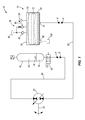
FIG. 1 is a schematic view illustrating an energy storage system according to a first construction of the invention. -
FIG. 2 is a schematic view illustrating an energy storage system according to a second construction of the invention. - Before any embodiments of the invention are explained in detail, it is to be understood that the invention is not limited in its application to the details of construction and the arrangement of components set forth in the following description or illustrated in the following drawings. The invention is capable of other embodiments and of being practiced or of being carried out in various ways. Also, it is to be understood that the phraseology and terminology used herein is for the purpose of description and should not be regarded as limiting.
-
FIG. 1 illustrates a first construction of anenergy storage system 10. Specifically, thesystem 10 is for use with a hybrid vehicle and is configured as a parallel hydraulicregenerative drive system 10 including areservoir 14, anaccumulator 18, and a reversible pump/motor 22 in selective fluid communication with theaccumulator 18 and in fluid communication with thereservoir 14. The reversible pump/motor 22 is configured as a variable displacement, axial-piston, swashplate-design pump/motor 22, such as a Bosch Rexroth Model No. A4VSO variable displacement, axial piston reversible pump/motor 22. Alternatively, the reversible pump/motor 22 may be configured having a constant displacement rather than a variable displacement. The reversible pump/motor 22 is drivably coupled to a rotating shaft 26 (e.g., an output shaft of an engine, an accessory drive system of the engine, a drive shaft between a transmission and an axle assembly, etc.). As is described in more detail below, the pump/motor 22 transfers power to the rotatingshaft 26 when operating as a motor, and the pump/motor 22 is driven by the rotatingshaft 26 when operating as a pump. Alternatively, thesystem 10 may be utilized in other applications (e.g., a mobile or an industrial hydraulic application, etc.). - The
accumulator 18 includes afirst chamber 30 containing a gas (e.g. nitrogen, etc.), asecond chamber 34 containing a working fluid (e.g. hydraulic fluid, etc.), and amovable piston 38 separating thechambers 30, 34 (schematically illustrated as a line between thechamber 30 and the chamber 34). Alternatively, theaccumulator 18 may be configured with a bladder or a diaphragm rather than thepiston 38. Thesystem 10 also includes anisolation valve 42 in fluid communication with theworking fluid chamber 34 in theaccumulator 18. Theisolation valve 42 selectively fluidly communicates theaccumulator 18 and the pump/motor 22. Theisolation valve 42 may be configured as a poppet valve, ball valve, spool valve, gate valve, cartridge valve, needle valve, block valve, etc. Further, theisolation valve 42 is solenoid-actuated to open and spring-biased to close. - With continued reference to
FIG. 1 , thereservoir 14 contains working fluid and is in fluid communication with the reversible pump/motor 22 by afluid passageway 50. A heat exchanger and/or a working fluid filter (not shown) may be situated in thefluid passageway 50 to facilitate cooling and filtering of the working fluid. The reversible pump/motor 22 is in fluid communication with thereservoir 14 to draw low-pressure working fluid (in the direction of arrow A) from thereservoir 14 via thefluid passageway 50 when operating as a pump. The reversible pump/motor 22 is also in fluid communication with thereservoir 14 to return low-pressure working fluid (in the direction of arrow B) to thereservoir 14 via thefluid passageway 50 when operating as a motor. - The reversible pump/
motor 22 is in fluid communication with theaccumulator 18 via afluid passageway 58 to deliver pressurized working fluid (in the direction of arrow A) to theaccumulator 18 when operating as a pump. The reversible pump/motor 22 is also in fluid communication with theaccumulator 18 via thefluid passageway 58 to receive pressurized working fluid (in the direction of arrow B) from theaccumulator 18 when operating as a motor. Theisolation valve 42 is situated in thefluid passageway 58 and blocks the flow of working fluid through thepassageway 58 when in a closed configuration, and permits the flow of working fluid through thepassageway 58 when in an open configuration. - With continued reference to
FIG. 1 , thereservoir 14 includes ahousing 62 defining aninterior chamber 66, and a collapsible,non-elastic bladder 70 positioned within theinterior chamber 66 of thehousing 62. As is discussed in more detail below, thehousing 62 is substantially air-tight and is capable of maintaining pressurized air within thehousing 62. In the illustrated construction of thesystem 10, thehousing 62 is schematically illustrated as having a generally rectangular shape. However, thehousing 62 may be configured having any of a number of different shapes to conform with the structure of a hybrid vehicle within which thehousing 62 is located. In addition, thehousing 62 may be made from any of the number of different materials (e.g., metals, plastics, composite materials, etc.). - The collapsible,
non-elastic bladder 70 defines aninterior chamber 72 within which working fluid is contained. Because thebladder 70 is non-elastic, the maximum volume of theinterior chamber 72 is a fixed value, in contrast with an elastic bladder defining a variable-volume interior chamber. Thebladder 70 is also non-rigid, and therefore generally conforms to the particular shape of theinterior chamber 66 of thehousing 62. In the illustrated construction of thesystem 10, thebladder 70 is schematically illustrated as assuming a generally rectangular shape as a result of being positioned within thehousing 62, which includes a generallyrectangular interior chamber 66. Alternatively, thebladder 70 may assume any of a number of different shapes depending upon the particular shape of thehousing 62. - The
bladder 70 includes a single inlet/outlet port 74 in fluid communication with thefluid passageway 50 through which working fluid passes to enter or exit thebladder 70. Alternatively, thebladder 70 may include separate inlet and outlet ports through which working fluid enters thebladder 70 and exits thebladder 70, respectively. Although not shown, thebladder 70 may include an air release valve to facilitate removal of air from thechamber 72 when thebladder 70 is filled with working fluid. As shown inFIG. 1 , all of the working fluid contained within thereservoir 14 during normal operation of thesystem 10 is located within thebladder 70. Thebladder 70 functions as a shield or barrier between the working fluid and the atmosphere (i.e., including the air or other gas within theinterior chamber 66 of the housing 62) to reduce the risk of any potential contamination of the working fluid from debris in the atmosphere or theinterior chamber 66 of thehousing 62. Alternatively, thebladder 70 may be omitted from thesystem 10, such that the working fluid is contained directly in the pressurizedhousing 62. - The
system 10 also includes abreather assembly 78 in fluid communication with theinterior chamber 66 of thehousing 62 that allows thereservoir 14 to self-pressurize during operation of thesystem 10 and the hybrid vehicle incorporating thesystem 10. As is described in more detail below, pressurization of the reservoir 14 (i.e., pressurization of theinterior chamber 66 of the housing 62) substantially ensures that the pressure of the working fluid at the inlet of the pump/motor 22 is maintained at a level sufficient to substantially prevent cavitation of the pump/motor 22 when operating as a pump. Thebreather assembly 78 includes a springless, one-way check valve 82 in fluid communication with theinterior chamber 66 of thehousing 62 that permits replacement air at atmospheric pressure to enter theinterior chamber 66 as the fluid level in thebladder 70 decreases, but prevents discharge or escape of air from theinterior chamber 66. Alternatively, thecheck valve 82 may include a spring to bias thecheck valve 82 to a closed configuration. - The
breather assembly 78 also includes a spring-biased, one-way pressurerelief check valve 86 in fluid communication with theinterior chamber 66 of thehousing 62 connected in parallel with the one-way check valve 82 to permit discharge of air from theinterior chamber 66 should the pressure in theinterior chamber 66 exceed some predetermined value. Bothvalves common breather 90, which directs replacement air from the atmosphere to thevalve 82, and directs discharged air from thevalve 86 to the atmosphere. - With continued reference to
FIG. 1 , thesystem 10 includes apressure sensor 94 in fluid communication with theinterior chamber 66 of thehousing 62 to detect the pressure in theinterior chamber 66. Thepressure sensor 94 may be employed with a diagnostic function to determine the existence of any leaks in thepressurized housing 62. For example, should the pressure within theinterior chamber 66 fall below some predetermined value during operation of thesystem 10, thepressure sensor 94 may provide a signal to an engine control unit ("ECU") or a separate control unit of the hybrid vehicle within which thesystem 10 is incorporated to cease operation of theregenerative drive system 10 of the hybrid vehicle. The ECU or separate control unit of the hybrid vehicle may also trigger an alarm (e.g., a visual alarm, an audible alarm, etc.) upon the pressure in theinterior chamber 66 falling below the predetermined value to warn the operator of the hybrid vehicle that maintenance is required on thesystem 10. - With continued reference to
FIG. 1 , thehousing 62 includes asump 98 within which any leaked working fluid from thebladder 70 may accumulate. Thesystem 10 may also include aleakage sensor 102 operable to detect any accumulated working fluid in thesump 98. Like thepressure sensor 94, theleakage sensor 102 may be employed with a diagnostic function to determine the existence of any leaks in thebladder 70. For example, upon detection of working fluid in thesump 98, theleakage sensor 102 may provide a signal to the ECU or a separate control unit of the hybrid vehicle within which thesystem 10 is incorporated to cease operation of theregenerative drive system 10 of the hybrid vehicle. The ECU or separate control unit of the hybrid vehicle may also trigger an alarm (e.g., a visual alarm, an audible alarm, etc.) upon detection of working fluid within thesump 98 by theleakage sensor 102 to warn the operator of the hybrid vehicle that maintenance is required on thesystem 10. - In operation, when the
system 10 recovers kinetic energy from the rotatingshaft 26, the pump/motor 22 operates as a pump to draw working fluid from thebladder 70 in the direction of arrow A, pressurize the working fluid, and pump the pressurized working fluid into the workingfluid chamber 34 of theaccumulator 18 through theopen isolation valve 42. As working fluid exits thebladder 70, thebladder 70 collapses upon itself (shown in phantom inFIG. 1 ), and replacement air is allowed into theinterior chamber 66 through the one-way check valve 82. After the kinetic energy of therotating shaft 26 is recovered, theisolation valve 42 is actuated to a closed configuration, and the compressed gas in thegas chamber 30 of theaccumulator 18 acts on thepiston 38 to maintain the working fluid at a high pressure within theaccumulator 18. - When the hybrid vehicle requires propulsion assistance, the
isolation valve 42 is actuated to an open configuration to permit the flow of pressurized working fluid in the direction of arrow B from theaccumulator 18. High-pressure working fluid flows from theaccumulator 18, through thefluid passageway 58, and into the pump/motor 22 to operate the pump/motor 22 as a motor to drive theshaft 26. The pump/motor 22 then returns the low-pressure working fluid to thebladder 70 via thefluid passageway 50. As the fluid level in thebladder 70 increases, the one-way check valve 82 and the pressurerelief check valve 86 remain closed and prevent air from escaping theinterior chamber 66 of thehousing 62. As a result, the pressure of the air in theinterior chamber 66 increases. Subsequent cycles of drawing replacement air into theinterior chamber 66 when the pump/motor 22 operates as a pump to draw working fluid from thebladder 70, and pressurizing the air in theinterior chamber 66 when the pump/motor 22 operates as a motor to return working fluid to thebladder 70, continue during operation of the hybrid vehicle. During each cycle, the pressure in theinterior chamber 66 is incrementally increased until a positive pressure (i.e., a pressure greater than atmospheric pressure) is exerted on thebladder 70 and the working fluid contained within thebladder 70. The pressure in theinterior chamber 66 is allowed to build or increase to a predetermined value by which the minimum required working fluid inlet pressure of the pump/motor 22 is satisfied to reduce or substantially prevent cavitation of the pump/motor 22 when operating as a pump. The pressurerelief check valve 86 would open to relieve the pressure in theinterior chamber 66 only when the pressure exceeds this predetermined value beyond a predetermined safety factor. -
FIG. 2 illustrates a second construction of anenergy storage system 110 for a hybrid vehicle, with like components labeled with like reference numerals. Thesystem 110 ofFIG. 2 is substantially similar to thesystem 10 ofFIG. 1 , with the exception that thesystem 110 ofFIG. 2 includes a source of compressed air or gas (e.g., an on-board pump or compressor 114) to provide an initial or "pre-charge" of air in theinterior chamber 66, prior to operation of the hybrid vehicle, to pressurize theinterior chamber 66 and exert a compressive force on thebladder 70 to meet the minimum required working fluid inlet pressure of the pump/motor 22. Thesystem 110 also includes a solenoid-actuatedisolation valve 118 fluidly connected between thereservoir 14 and thecompressor 114. Alternatively, should thecompressor 114 be dedicated to thesystem 10, theisolation valve 118 may be replaced with a check valve. - In the illustrated construction of the
system 110, thecompressor 114 andvalve 118 are in fluid communication with theinterior chamber 66 in a parallel relationship with thevalve 82. In other words, the pressurized air provided by thecompressor 114, and the atmospheric replacement air passing through thevalve 82, enter theinterior chamber 66 through separate passageways. Alternatively, the outlet of theisolation valve 118 may be fluidly connected to the passageway in which thevalve 82 is situated at a location upstream of thevalve 82, such that the pre-charge of pressurized air provided by thecompressor 114 passes through thevalve 82 before entering theinterior chamber 66. - When the hybrid vehicle incorporating the
system 110 is started, theisolation valve 118 is actuated to an open configuration, and thecompressor 114 is activated to pump pressurized air into theinterior chamber 66 to pressurize theinterior chamber 66 to a predetermined value at which the force exerted on the bladder 70 (and the working fluid contained within the bladder 70) is sufficient to meet the minimum required working fluid inlet pressure of the pump/motor 22. When thepressure sensor 94 detects that the pressure in theinterior chamber 66 has reached this predetermined value, theisolation valve 118 is actuated to a closed configuration and thecompressor 114 is deactivated. As a result, the minimum required working fluid inlet pressure of the pump/motor 22 is satisfied without first requiring repeated cycles of drawing replacement air into theinterior chamber 66 when the pump/motor 22 operates as a pump to draw working fluid from thebladder 70, and pressurizing the air in theinterior chamber 66 when the pump/motor 22 operates as a motor to return working fluid to thebladder 70. However, after the first cycle of drawing replacement air into theinterior chamber 66 when the pump/motor 22 operates as a pump to draw working fluid from thebladder 70, and pressurizing the air in theinterior chamber 66 when the pump/motor 22 operates as a motor to return working fluid to thebladder 70, thesystem 110 operates substantially similarly as thesystem 10 ofFIG. 1 . - Various features of the invention are set forth in the following claims.
Claims (15)
- An energy storage system (10; 110) comprising:a reservoir (14) defining an interior chamber (66);a collapsible bladder (70);a reversible pump/motor (22) in fluid communication with the bladder (70); andan accumulator (18) containing working fluid and gas, the accumulator (18) in selective fluid communication with the reversible pump/motor (22) to deliver pressurized working fluid to the reversible pump/motor (22) when operating as a motor, and to receive pressurized working fluid discharged by the reversible pump/motor (22) when operating as a pump;characterized in that the collapsible bladder (70) is positioned within the interior chamber (66), the bladder (70) having working fluid therein; andin that it comprises a one-way valve (82) in fluid communication with the interior chamber (66) and operable to permit entry of replacement air into the interior chamber (66) as working fluid exits the bladder (70).
- The energy storage system (10; 110) of claim 1, further comprising a pressure relief valve (86) in fluid communication with the interior chamber (66) of the reservoir (18) and operable to prevent ventilation of the replacement air from the interior chamber (66) below a predetermined threshold pressure when working fluid enters the collapsible bladder (70).
- The energy storage system (110) of claim 1, further comprising an air pump (114) in selective fluid communication with the interior chamber (66) of the reservoir (18) and operable to fill the interior chamber (66) with pressurized air to exert a compressive force on the bladder (70).
- The energy storage system (10; 110) of claim 1, further comprising a pressure sensor (94) in fluid communication with the interior chamber (66) of the reservoir (18) to detect the air pressure in the interior chamber (66).
- The energy storage system (10; 110) of claim 1, wherein the reservoir (18) includes a sump (98) positioned below the bladder (70).
- The energy storage system (10; 110) of claim 5, further comprising a sensor (102) operable to detect working fluid in the sump (98) leaked from the bladder (70).
- The energy storage system (10; 110) of claim 1, wherein working fluid is drawn from the bladder (70) by the reversible pump/motor (22) when operating as a pump.
- The energy storage system (10; 110) of claim 1, wherein the bladder (70) defines an interior chamber (72), and wherein the reversible pump/motor (22) is in fluid communication with the interior chamber (72) of the bladder (70).
- The energy storage system (10; 110) of claim 1, wherein the bladder (70) is non-elastic.
- A method of operating an energy storage system (10; 110), the method comprising:providing a reservoir (18) defining an interior chamber (66);positioning a collapsible bladder (70);returning working fluid to the bladder (70) with a reversible pump/motor (22) when operating as a motor; anddrawing working fluid from the collapsible bladder (70) when the reversible pump/motor (22) is operating as a pump;characterized in that the method further comprises:positioning the collapsible bladder (70) within the interior chamber (66); andpermitting replacement air to enter the interior chamber (66) of the reservoir (18) when working fluid is drawn from the collapsible bladder (70).
- The method of claim 10, further comprising preventing ventilation of the replacement air from the interior chamber (66) below a predetermined threshold pressure in the interior chamber (66) when working fluid is returned to the collapsible bladder (70).
- The method of claim 10, further comprising filling the interior chamber (66) with pressurized air before working fluid is drawn from the bladder (70).
- The method of claim 12, wherein filling the interior chamber (66) with pressurized air occurs before working fluid is returned to the collapsible bladder (70).
- The method of claim 10, further comprising monitoring the air pressure in the interior chamber (66) of the reservoir (18).
- The method of claim 10, further comprising:providing a sump (98) below the collapsible bladder (70); andmonitoring the sump (98) for working fluid leaked from the bladder (70) and accumulating in the sump (98).
Applications Claiming Priority (2)
| Application Number | Priority Date | Filing Date | Title |
|---|---|---|---|
| US12/622,880 US8250861B2 (en) | 2009-11-20 | 2009-11-20 | Energy storage system including pressurized reservoir |
| PCT/US2010/057145 WO2011063071A1 (en) | 2009-11-20 | 2010-11-18 | Energy storage system including pressurized reservoir |
Publications (2)
| Publication Number | Publication Date |
|---|---|
| EP2501579A1 EP2501579A1 (en) | 2012-09-26 |
| EP2501579B1 true EP2501579B1 (en) | 2014-06-11 |
Family
ID=43531038
Family Applications (1)
| Application Number | Title | Priority Date | Filing Date |
|---|---|---|---|
| EP10782502.8A Not-in-force EP2501579B1 (en) | 2009-11-20 | 2010-11-18 | Energy storage system including pressurized reservoir |
Country Status (5)
| Country | Link |
|---|---|
| US (1) | US8250861B2 (en) |
| EP (1) | EP2501579B1 (en) |
| CN (1) | CN102612445B (en) |
| CA (1) | CA2781282C (en) |
| WO (1) | WO2011063071A1 (en) |
Families Citing this family (17)
| Publication number | Priority date | Publication date | Assignee | Title |
|---|---|---|---|---|
| RU2444649C1 (en) * | 2010-07-13 | 2012-03-10 | Александр Анатольевич Строганов | Hydraulic energy recovery device |
| US8146559B2 (en) * | 2009-07-21 | 2012-04-03 | International Truck Intellectual Property Company, Llc | Vehicle hybridization system |
| DE102010026092A1 (en) * | 2010-07-05 | 2012-01-05 | Robert Bosch Gmbh | Pressure accumulator device for connection to a hydraulic system |
| US20120273076A1 (en) * | 2011-04-28 | 2012-11-01 | Robert Bosch Gmbh | Compact hydraulic accumulator |
| US8701398B2 (en) * | 2012-03-20 | 2014-04-22 | Robert Bosch Gmbh | Strain energy accumulator |
| FR3012192B1 (en) * | 2013-10-21 | 2015-12-25 | Peugeot Citroen Automobiles Sa | ENERGY STORAGE DEVICE COMPRISING A FLUID |
| US9194284B2 (en) | 2014-02-28 | 2015-11-24 | Deere & Company | Reservoir pressurization |
| GB2524787A (en) * | 2014-04-02 | 2015-10-07 | Eurekagen Ltd | Energy recovery system |
| DE102015206092A1 (en) * | 2015-04-02 | 2016-10-06 | Conti Temic Microelectronic Gmbh | Device for damping pressure fluctuations |
| US10030675B2 (en) * | 2015-04-13 | 2018-07-24 | Caterpillar Inc. | System for stabilizing pressure fluctuations in a hydraulic line of a hydraulic circuit |
| JP6510876B2 (en) * | 2015-05-01 | 2019-05-08 | 株式会社神戸製鋼所 | Compressed air storage power generation method and compressed air storage power generation device |
| CN108778755B (en) * | 2016-05-26 | 2020-11-03 | 惠普发展公司,有限责任合伙企业 | buffer memory |
| US10415469B2 (en) | 2017-08-25 | 2019-09-17 | Savannah River Nuclear Solutions, Llc | Hybrid compressed air/water energy storage system and method |
| CN108357355B (en) * | 2018-01-24 | 2021-08-27 | 南京依维柯汽车有限公司 | Automobile with driving energy storage function |
| CN108799212B (en) * | 2018-07-24 | 2019-08-16 | 吉林大学 | An emergency standby power device for a hydraulic system |
| RU2710109C1 (en) * | 2019-05-16 | 2019-12-24 | Сергей Яковлевич Данилов | Method for secondary use of compressed air in a production process |
| CN116605391B (en) * | 2023-05-17 | 2026-01-13 | 中国船舶集团有限公司第七一九研究所 | Power system and application thereof |
Family Cites Families (27)
| Publication number | Priority date | Publication date | Assignee | Title |
|---|---|---|---|---|
| US3846983A (en) * | 1973-11-19 | 1974-11-12 | Caterpillar Tractor Co | Hydraulic fluid reservoir pressurization arrangement |
| US3976124A (en) * | 1974-11-21 | 1976-08-24 | Pettibone Corporation | Cooling-controlled tank for hydraulic fluid |
| IT1071164B (en) * | 1976-07-28 | 1985-04-02 | Fiat Allis Macch Movi | DEVICE FOR PRESSURIZING A LIQUID IN A TANK..PARTICULARLY FOR HYDRAULIC VEHICLE SYSTEMS |
| US4441573A (en) * | 1980-09-04 | 1984-04-10 | Advanced Energy Systems Inc. | Fuel-efficient energy storage automotive drive system |
| US4566565A (en) * | 1984-04-30 | 1986-01-28 | General Motors Corporation | Self-pressurized damper |
| DE3705642A1 (en) * | 1986-07-02 | 1988-01-14 | Man Nutzfahrzeuge Gmbh | ENERGY STORAGE AND DELIVERY DEVICE |
| US4760697A (en) * | 1986-08-13 | 1988-08-02 | National Research Council Of Canada | Mechanical power regeneration system |
| US4723577A (en) * | 1986-10-22 | 1988-02-09 | Sundstrand Corporation | Thermal expansion reservoir |
| US4784354A (en) * | 1987-09-28 | 1988-11-15 | Tavano John B | Emergency aircraft fuel system |
| US4852765A (en) * | 1988-09-12 | 1989-08-01 | Chrysler Motors Corporation | Fuel tank with bladder |
| WO2000046056A1 (en) * | 1999-02-05 | 2000-08-10 | Powerlight Corporation | Electric vehicle photovoltaic charging system |
| US6834737B2 (en) * | 2000-10-02 | 2004-12-28 | Steven R. Bloxham | Hybrid vehicle and energy storage system and method |
| MXPA03004752A (en) * | 2000-11-28 | 2005-10-18 | Shep Ltd | Hydraulic energy storage systems. |
| US6604795B2 (en) * | 2000-12-28 | 2003-08-12 | Toyota Jidosha Kabushiki Kaisha | Braking system including high-pressure source between master cylinder and brake cylinder |
| US7121304B2 (en) * | 2001-12-19 | 2006-10-17 | The United States Of America As Represented By The Administrator Of The U.S. Environmental Protection Agency | Low permeation hydraulic accumulator |
| US7290389B2 (en) | 2003-07-22 | 2007-11-06 | Eaton Corporation | Hydraulic drive system and improved filter sub-system therefor |
| US7150508B2 (en) * | 2004-04-19 | 2006-12-19 | Kelsey-Hayes Company | Modular regenerative braking |
| US7147239B2 (en) | 2004-07-01 | 2006-12-12 | Ford Global Technologies, Llc | Wheel creep control of hydraulic hybrid vehicle using regenerative braking |
| US7232192B2 (en) * | 2004-07-01 | 2007-06-19 | Ford Global Technologies, Llc | Deadband regenerative braking control for hydraulic hybrid vehicle powertrain |
| US7273122B2 (en) * | 2004-09-30 | 2007-09-25 | Bosch Rexroth Corporation | Hybrid hydraulic drive system with engine integrated hydraulic machine |
| CN1833901A (en) * | 2006-03-10 | 2006-09-20 | 上海交大神舟汽车设计开发有限公司 | Automotive braking force reclaiming economizing and accelerating unit |
| GB0614930D0 (en) | 2006-07-27 | 2006-09-06 | Arternis Intelligent Power Ltd | Hydrostatic regenerative drive system |
| US7843076B2 (en) * | 2006-11-29 | 2010-11-30 | Yshape Inc. | Hydraulic energy accumulator |
| CN201108641Y (en) * | 2007-10-26 | 2008-09-03 | 凌孝民 | Portable intelligent transfusion utensil |
| US8166753B2 (en) * | 2008-11-24 | 2012-05-01 | Robert Bosch Gmbh | Accumulator system and method of monitoring same |
| US8186155B2 (en) * | 2009-01-30 | 2012-05-29 | Robert Bosch Gmbh | Hydraulic energy storage system with accumulator and method of varying charge of same |
| US7913791B2 (en) * | 2009-05-04 | 2011-03-29 | Robert Bosch Gmbh | Energy storage system for a hybrid vehicle |
-
2009
- 2009-11-20 US US12/622,880 patent/US8250861B2/en not_active Expired - Fee Related
-
2010
- 2010-11-18 CA CA2781282A patent/CA2781282C/en not_active Expired - Fee Related
- 2010-11-18 CN CN201080052038.3A patent/CN102612445B/en not_active Expired - Fee Related
- 2010-11-18 EP EP10782502.8A patent/EP2501579B1/en not_active Not-in-force
- 2010-11-18 WO PCT/US2010/057145 patent/WO2011063071A1/en not_active Ceased
Also Published As
| Publication number | Publication date |
|---|---|
| CA2781282C (en) | 2013-01-15 |
| US20110120107A1 (en) | 2011-05-26 |
| CN102612445A (en) | 2012-07-25 |
| CN102612445B (en) | 2015-06-17 |
| WO2011063071A1 (en) | 2011-05-26 |
| US8250861B2 (en) | 2012-08-28 |
| EP2501579A1 (en) | 2012-09-26 |
| CA2781282A1 (en) | 2011-05-26 |
Similar Documents
| Publication | Publication Date | Title |
|---|---|---|
| CA2781282C (en) | Energy storage system including pressurized reservoir | |
| JP4370096B2 (en) | Hydraulic energy storage system | |
| EP2486286B1 (en) | Energy storage system including an expandable accumulator and reservoir assembly | |
| US20100276221A1 (en) | Energy storage system for a hybrid vehicle | |
| US20040050042A1 (en) | Emergercy energy release for hydraulic energy storage systems | |
| US20100192563A1 (en) | Hydraulic energy storage system with accumulator and method of varying charge of same | |
| US20110139285A1 (en) | Combination spring and gas filled accumulator | |
| US8166753B2 (en) | Accumulator system and method of monitoring same | |
| KR20060047333A (en) | Hydraulic Drive System and Improved Filter Subsystem | |
| EP2828536A1 (en) | Strain energy accumulator | |
| CN117795201A (en) | Pump construction including purge valve | |
| CN114278629A (en) | Hydraulic oil tank, hydraulic system and air pressure balancing method of hydraulic oil tank | |
| US20160303962A1 (en) | Hydraulic circuit for a hybrid vehicle comprising a very high pressure circuit and safety means in case of overpressure | |
| AU2002230015B2 (en) | Hydraulic energy storage systems | |
| AU2002230015A1 (en) | Hydraulic energy storage systems | |
| CN108386356B (en) | Movable single-screw compressor | |
| US20050016166A1 (en) | Hydraulic drive system and improved filter sub-system therefor | |
| JPH0569722A (en) | Vehicle suspension device |
Legal Events
| Date | Code | Title | Description |
|---|---|---|---|
| PUAI | Public reference made under article 153(3) epc to a published international application that has entered the european phase |
Free format text: ORIGINAL CODE: 0009012 |
|
| 17P | Request for examination filed |
Effective date: 20120620 |
|
| AK | Designated contracting states |
Kind code of ref document: A1 Designated state(s): AL AT BE BG CH CY CZ DE DK EE ES FI FR GB GR HR HU IE IS IT LI LT LU LV MC MK MT NL NO PL PT RO RS SE SI SK SM TR |
|
| DAX | Request for extension of the european patent (deleted) | ||
| GRAP | Despatch of communication of intention to grant a patent |
Free format text: ORIGINAL CODE: EPIDOSNIGR1 |
|
| INTG | Intention to grant announced |
Effective date: 20140117 |
|
| GRAS | Grant fee paid |
Free format text: ORIGINAL CODE: EPIDOSNIGR3 |
|
| GRAA | (expected) grant |
Free format text: ORIGINAL CODE: 0009210 |
|
| AK | Designated contracting states |
Kind code of ref document: B1 Designated state(s): AL AT BE BG CH CY CZ DE DK EE ES FI FR GB GR HR HU IE IS IT LI LT LU LV MC MK MT NL NO PL PT RO RS SE SI SK SM TR |
|
| REG | Reference to a national code |
Ref country code: GB Ref legal event code: FG4D |
|
| REG | Reference to a national code |
Ref country code: CH Ref legal event code: EP |
|
| REG | Reference to a national code |
Ref country code: IE Ref legal event code: FG4D |
|
| REG | Reference to a national code |
Ref country code: AT Ref legal event code: REF Ref document number: 672074 Country of ref document: AT Kind code of ref document: T Effective date: 20140715 |
|
| REG | Reference to a national code |
Ref country code: DE Ref legal event code: R096 Ref document number: 602010016688 Country of ref document: DE Effective date: 20140724 |
|
| REG | Reference to a national code |
Ref country code: SE Ref legal event code: TRGR |
|
| PG25 | Lapsed in a contracting state [announced via postgrant information from national office to epo] |
Ref country code: LT Free format text: LAPSE BECAUSE OF FAILURE TO SUBMIT A TRANSLATION OF THE DESCRIPTION OR TO PAY THE FEE WITHIN THE PRESCRIBED TIME-LIMIT Effective date: 20140611 Ref country code: FI Free format text: LAPSE BECAUSE OF FAILURE TO SUBMIT A TRANSLATION OF THE DESCRIPTION OR TO PAY THE FEE WITHIN THE PRESCRIBED TIME-LIMIT Effective date: 20140611 Ref country code: NO Free format text: LAPSE BECAUSE OF FAILURE TO SUBMIT A TRANSLATION OF THE DESCRIPTION OR TO PAY THE FEE WITHIN THE PRESCRIBED TIME-LIMIT Effective date: 20140911 Ref country code: GR Free format text: LAPSE BECAUSE OF FAILURE TO SUBMIT A TRANSLATION OF THE DESCRIPTION OR TO PAY THE FEE WITHIN THE PRESCRIBED TIME-LIMIT Effective date: 20140912 |
|
| REG | Reference to a national code |
Ref country code: NL Ref legal event code: VDEP Effective date: 20140611 |
|
| REG | Reference to a national code |
Ref country code: AT Ref legal event code: MK05 Ref document number: 672074 Country of ref document: AT Kind code of ref document: T Effective date: 20140611 |
|
| REG | Reference to a national code |
Ref country code: LT Ref legal event code: MG4D |
|
| PG25 | Lapsed in a contracting state [announced via postgrant information from national office to epo] |
Ref country code: RS Free format text: LAPSE BECAUSE OF FAILURE TO SUBMIT A TRANSLATION OF THE DESCRIPTION OR TO PAY THE FEE WITHIN THE PRESCRIBED TIME-LIMIT Effective date: 20140611 Ref country code: HR Free format text: LAPSE BECAUSE OF FAILURE TO SUBMIT A TRANSLATION OF THE DESCRIPTION OR TO PAY THE FEE WITHIN THE PRESCRIBED TIME-LIMIT Effective date: 20140611 Ref country code: LV Free format text: LAPSE BECAUSE OF FAILURE TO SUBMIT A TRANSLATION OF THE DESCRIPTION OR TO PAY THE FEE WITHIN THE PRESCRIBED TIME-LIMIT Effective date: 20140611 |
|
| PG25 | Lapsed in a contracting state [announced via postgrant information from national office to epo] |
Ref country code: SK Free format text: LAPSE BECAUSE OF FAILURE TO SUBMIT A TRANSLATION OF THE DESCRIPTION OR TO PAY THE FEE WITHIN THE PRESCRIBED TIME-LIMIT Effective date: 20140611 Ref country code: RO Free format text: LAPSE BECAUSE OF FAILURE TO SUBMIT A TRANSLATION OF THE DESCRIPTION OR TO PAY THE FEE WITHIN THE PRESCRIBED TIME-LIMIT Effective date: 20140611 Ref country code: EE Free format text: LAPSE BECAUSE OF FAILURE TO SUBMIT A TRANSLATION OF THE DESCRIPTION OR TO PAY THE FEE WITHIN THE PRESCRIBED TIME-LIMIT Effective date: 20140611 Ref country code: PT Free format text: LAPSE BECAUSE OF FAILURE TO SUBMIT A TRANSLATION OF THE DESCRIPTION OR TO PAY THE FEE WITHIN THE PRESCRIBED TIME-LIMIT Effective date: 20141013 Ref country code: CZ Free format text: LAPSE BECAUSE OF FAILURE TO SUBMIT A TRANSLATION OF THE DESCRIPTION OR TO PAY THE FEE WITHIN THE PRESCRIBED TIME-LIMIT Effective date: 20140611 Ref country code: ES Free format text: LAPSE BECAUSE OF FAILURE TO SUBMIT A TRANSLATION OF THE DESCRIPTION OR TO PAY THE FEE WITHIN THE PRESCRIBED TIME-LIMIT Effective date: 20140611 |
|
| PG25 | Lapsed in a contracting state [announced via postgrant information from national office to epo] |
Ref country code: NL Free format text: LAPSE BECAUSE OF FAILURE TO SUBMIT A TRANSLATION OF THE DESCRIPTION OR TO PAY THE FEE WITHIN THE PRESCRIBED TIME-LIMIT Effective date: 20140611 Ref country code: AT Free format text: LAPSE BECAUSE OF FAILURE TO SUBMIT A TRANSLATION OF THE DESCRIPTION OR TO PAY THE FEE WITHIN THE PRESCRIBED TIME-LIMIT Effective date: 20140611 Ref country code: PL Free format text: LAPSE BECAUSE OF FAILURE TO SUBMIT A TRANSLATION OF THE DESCRIPTION OR TO PAY THE FEE WITHIN THE PRESCRIBED TIME-LIMIT Effective date: 20140611 Ref country code: IS Free format text: LAPSE BECAUSE OF FAILURE TO SUBMIT A TRANSLATION OF THE DESCRIPTION OR TO PAY THE FEE WITHIN THE PRESCRIBED TIME-LIMIT Effective date: 20141011 |
|
| REG | Reference to a national code |
Ref country code: DE Ref legal event code: R097 Ref document number: 602010016688 Country of ref document: DE |
|
| PLBE | No opposition filed within time limit |
Free format text: ORIGINAL CODE: 0009261 |
|
| STAA | Information on the status of an ep patent application or granted ep patent |
Free format text: STATUS: NO OPPOSITION FILED WITHIN TIME LIMIT |
|
| PG25 | Lapsed in a contracting state [announced via postgrant information from national office to epo] |
Ref country code: DK Free format text: LAPSE BECAUSE OF FAILURE TO SUBMIT A TRANSLATION OF THE DESCRIPTION OR TO PAY THE FEE WITHIN THE PRESCRIBED TIME-LIMIT Effective date: 20140611 Ref country code: IT Free format text: LAPSE BECAUSE OF FAILURE TO SUBMIT A TRANSLATION OF THE DESCRIPTION OR TO PAY THE FEE WITHIN THE PRESCRIBED TIME-LIMIT Effective date: 20140611 |
|
| 26N | No opposition filed |
Effective date: 20150312 |
|
| REG | Reference to a national code |
Ref country code: DE Ref legal event code: R097 Ref document number: 602010016688 Country of ref document: DE Effective date: 20150312 |
|
| PG25 | Lapsed in a contracting state [announced via postgrant information from national office to epo] |
Ref country code: BE Free format text: LAPSE BECAUSE OF FAILURE TO SUBMIT A TRANSLATION OF THE DESCRIPTION OR TO PAY THE FEE WITHIN THE PRESCRIBED TIME-LIMIT Effective date: 20140611 Ref country code: MC Free format text: LAPSE BECAUSE OF FAILURE TO SUBMIT A TRANSLATION OF THE DESCRIPTION OR TO PAY THE FEE WITHIN THE PRESCRIBED TIME-LIMIT Effective date: 20140611 Ref country code: LU Free format text: LAPSE BECAUSE OF FAILURE TO SUBMIT A TRANSLATION OF THE DESCRIPTION OR TO PAY THE FEE WITHIN THE PRESCRIBED TIME-LIMIT Effective date: 20141118 |
|
| REG | Reference to a national code |
Ref country code: CH Ref legal event code: PL |
|
| PG25 | Lapsed in a contracting state [announced via postgrant information from national office to epo] |
Ref country code: SI Free format text: LAPSE BECAUSE OF FAILURE TO SUBMIT A TRANSLATION OF THE DESCRIPTION OR TO PAY THE FEE WITHIN THE PRESCRIBED TIME-LIMIT Effective date: 20140611 Ref country code: CH Free format text: LAPSE BECAUSE OF NON-PAYMENT OF DUE FEES Effective date: 20141130 Ref country code: LI Free format text: LAPSE BECAUSE OF NON-PAYMENT OF DUE FEES Effective date: 20141130 |
|
| REG | Reference to a national code |
Ref country code: IE Ref legal event code: MM4A |
|
| PG25 | Lapsed in a contracting state [announced via postgrant information from national office to epo] |
Ref country code: IE Free format text: LAPSE BECAUSE OF NON-PAYMENT OF DUE FEES Effective date: 20141118 |
|
| REG | Reference to a national code |
Ref country code: FR Ref legal event code: PLFP Year of fee payment: 6 |
|
| PG25 | Lapsed in a contracting state [announced via postgrant information from national office to epo] |
Ref country code: SM Free format text: LAPSE BECAUSE OF FAILURE TO SUBMIT A TRANSLATION OF THE DESCRIPTION OR TO PAY THE FEE WITHIN THE PRESCRIBED TIME-LIMIT Effective date: 20140611 |
|
| PGFP | Annual fee paid to national office [announced via postgrant information from national office to epo] |
Ref country code: DE Payment date: 20160126 Year of fee payment: 6 |
|
| PG25 | Lapsed in a contracting state [announced via postgrant information from national office to epo] |
Ref country code: BG Free format text: LAPSE BECAUSE OF FAILURE TO SUBMIT A TRANSLATION OF THE DESCRIPTION OR TO PAY THE FEE WITHIN THE PRESCRIBED TIME-LIMIT Effective date: 20140611 Ref country code: CY Free format text: LAPSE BECAUSE OF FAILURE TO SUBMIT A TRANSLATION OF THE DESCRIPTION OR TO PAY THE FEE WITHIN THE PRESCRIBED TIME-LIMIT Effective date: 20140611 |
|
| PG25 | Lapsed in a contracting state [announced via postgrant information from national office to epo] |
Ref country code: MT Free format text: LAPSE BECAUSE OF FAILURE TO SUBMIT A TRANSLATION OF THE DESCRIPTION OR TO PAY THE FEE WITHIN THE PRESCRIBED TIME-LIMIT Effective date: 20140611 Ref country code: HU Free format text: LAPSE BECAUSE OF FAILURE TO SUBMIT A TRANSLATION OF THE DESCRIPTION OR TO PAY THE FEE WITHIN THE PRESCRIBED TIME-LIMIT; INVALID AB INITIO Effective date: 20101118 Ref country code: TR Free format text: LAPSE BECAUSE OF FAILURE TO SUBMIT A TRANSLATION OF THE DESCRIPTION OR TO PAY THE FEE WITHIN THE PRESCRIBED TIME-LIMIT Effective date: 20140611 |
|
| REG | Reference to a national code |
Ref country code: FR Ref legal event code: PLFP Year of fee payment: 7 |
|
| PGFP | Annual fee paid to national office [announced via postgrant information from national office to epo] |
Ref country code: FR Payment date: 20161124 Year of fee payment: 7 Ref country code: GB Payment date: 20161124 Year of fee payment: 7 |
|
| PGFP | Annual fee paid to national office [announced via postgrant information from national office to epo] |
Ref country code: SE Payment date: 20161124 Year of fee payment: 7 |
|
| REG | Reference to a national code |
Ref country code: DE Ref legal event code: R119 Ref document number: 602010016688 Country of ref document: DE |
|
| PG25 | Lapsed in a contracting state [announced via postgrant information from national office to epo] |
Ref country code: DE Free format text: LAPSE BECAUSE OF NON-PAYMENT OF DUE FEES Effective date: 20170601 |
|
| PG25 | Lapsed in a contracting state [announced via postgrant information from national office to epo] |
Ref country code: MK Free format text: LAPSE BECAUSE OF FAILURE TO SUBMIT A TRANSLATION OF THE DESCRIPTION OR TO PAY THE FEE WITHIN THE PRESCRIBED TIME-LIMIT Effective date: 20140611 |
|
| REG | Reference to a national code |
Ref country code: SE Ref legal event code: EUG |
|
| GBPC | Gb: european patent ceased through non-payment of renewal fee |
Effective date: 20171118 |
|
| PG25 | Lapsed in a contracting state [announced via postgrant information from national office to epo] |
Ref country code: SE Free format text: LAPSE BECAUSE OF NON-PAYMENT OF DUE FEES Effective date: 20171119 |
|
| REG | Reference to a national code |
Ref country code: FR Ref legal event code: ST Effective date: 20180731 |
|
| PG25 | Lapsed in a contracting state [announced via postgrant information from national office to epo] |
Ref country code: FR Free format text: LAPSE BECAUSE OF NON-PAYMENT OF DUE FEES Effective date: 20171130 Ref country code: AL Free format text: LAPSE BECAUSE OF FAILURE TO SUBMIT A TRANSLATION OF THE DESCRIPTION OR TO PAY THE FEE WITHIN THE PRESCRIBED TIME-LIMIT Effective date: 20140611 |
|
| PG25 | Lapsed in a contracting state [announced via postgrant information from national office to epo] |
Ref country code: GB Free format text: LAPSE BECAUSE OF NON-PAYMENT OF DUE FEES Effective date: 20171118 |