EP2501330B1 - Rotating clip orthodontic bracket - Google Patents
Rotating clip orthodontic bracket Download PDFInfo
- Publication number
- EP2501330B1 EP2501330B1 EP10831890.8A EP10831890A EP2501330B1 EP 2501330 B1 EP2501330 B1 EP 2501330B1 EP 10831890 A EP10831890 A EP 10831890A EP 2501330 B1 EP2501330 B1 EP 2501330B1
- Authority
- EP
- European Patent Office
- Prior art keywords
- archwire
- bracket
- rotating clip
- orthodontic bracket
- archwire slot
- Prior art date
- Legal status (The legal status is an assumption and is not a legal conclusion. Google has not performed a legal analysis and makes no representation as to the accuracy of the status listed.)
- Not-in-force
Links
- 239000002184 metal Substances 0.000 claims description 4
- 239000000919 ceramic Substances 0.000 claims description 3
- 238000003780 insertion Methods 0.000 claims description 3
- 230000037431 insertion Effects 0.000 claims description 3
- 239000000463 material Substances 0.000 claims description 3
- 239000004033 plastic Substances 0.000 claims description 3
- 239000003086 colorant Substances 0.000 claims 1
- 238000010079 rubber tapping Methods 0.000 claims 1
- 230000000007 visual effect Effects 0.000 description 4
- 241001315286 Damon Species 0.000 description 2
- 230000004048 modification Effects 0.000 description 2
- 238000012986 modification Methods 0.000 description 2
- 230000000717 retained effect Effects 0.000 description 2
- 210000003484 anatomy Anatomy 0.000 description 1
- 230000001419 dependent effect Effects 0.000 description 1
- 239000013013 elastic material Substances 0.000 description 1
- 230000001815 facial effect Effects 0.000 description 1
- 230000002452 interceptive effect Effects 0.000 description 1
- 230000014759 maintenance of location Effects 0.000 description 1
- 238000004519 manufacturing process Methods 0.000 description 1
- 230000000737 periodic effect Effects 0.000 description 1
- 230000000284 resting effect Effects 0.000 description 1
- 230000008719 thickening Effects 0.000 description 1
Images




Classifications
-
- A—HUMAN NECESSITIES
- A61—MEDICAL OR VETERINARY SCIENCE; HYGIENE
- A61C—DENTISTRY; APPARATUS OR METHODS FOR ORAL OR DENTAL HYGIENE
- A61C7/00—Orthodontics, i.e. obtaining or maintaining the desired position of teeth, e.g. by straightening, evening, regulating, separating, or by correcting malocclusions
- A61C7/12—Brackets; Arch wires; Combinations thereof; Accessories therefor
- A61C7/28—Securing arch wire to bracket
- A61C7/285—Locking by rotation
Definitions
- the present invention is directed to a locking orthodontic bracket that contains a mechanism that rotationally locks an orthodontic archwire within the bracket archwire slot.
- Orthodontic brackets attached to teeth transmit forces, such as produced by an archwire, to move the teeth. Brackets usually contain an archwire slot for reception of the archwire. Orthodontic brackets today are typically bonded to a tooth or welded to an orthodontic band that is cemented to the tooth.
- Brackets commonly use tie wings that project upwardly and downwardly in pairs at the top and bottom of the installed bracket, respectively. These wings permit the archwire to be held within the archwire slot of the bracket by means of a twisted wire (ligature) or an elastomeric o-ring.
- ligature twisted wire
- elastomeric o-ring elastomeric o-ring
- U.S. Pat. No. 5,094,614 to Wildman discloses a sliding closure that engages the front of the archwire.
- the closure is recessed from the front or anterior surfaces of the disclosed bracket.
- These sliding closures are also found in U.S. Pat. No. 2,549,528 to Russell , U.S. Pat. No. 2,671,964 to Russell et al. and in U.S. Pat. No. 3,131,474 to Johnson .
- Sliding closures require the archwire also to be recessed within the archwire slot before the closure can be moved over the archwire making it very difficult for the user to visually confirm that the archwire is properly seated within the archwire slot.
- a conventional bracket has a visual front surface adjacent to the archwire slot making it easy to see if the archwire is seated in the archwire slot. This is not true in the recessed sliding closures. The actual archwire slot surface is beneath the sliding closure. Damon solved this problem in U.S. Pat. Nos. 5,275,557 (Jan. 4, 1994 ), 5,429,500 (Jul. 4, 1995 ) and 5,466,151 (Nov. 14, 1995 ).
- Pletcher U.S. Pat. No. 5,322,435 , discloses a locking slide member that is flat and guided by upright slots formed along both sides of the bracket and spanning the archwire slot thereby obscuring visual access to the critical corners of the archwire slots at the side edges of the bracket. Without this visual access being clear, one installing an archwire within a bracket cannot be certain as to proper seating of an archwire within the archwire slot before the slide cover is moved to a closed position. No tie wings or lugs are included in the illustrated bracket forms.
- brackets There is a modern esthetic requirement that the brackets be small. A drawback of many self-ligating brackets the locking covers increase the size of the bracket.
- a sliding spring cover, a hinged locking cover, a rotary sliding cover, a ball type rotatable cover etc. have been disclosed in different U.S. Patents. "Activa” produced by A Company, “Speed” and “Edgelock” produced by Ormco Corporation, and others are typical examples of ligature-less brackets that are commercially available.
- US 2104192 discloses a locking orthodontic bracket having an orthodontic bracket that contains a rotating clip for locking an orthodontic archwire within the archwire slot of the orthodontic bracket.
- the orthodontic bracket comprises a body containing a slot to receive an archwire, a base that is attachable to an orthodontic band or directly to a tooth surface, and a central recess on the front surface of the body that extends inwardly towards the base of the bracket. Rotation of the clip in one direction leaves the archwire slot open for the insertion or removal of an archwire and rotation in the opposite direction locks the archwire in the archwire slot.
- An orthodontic bracket according to the present invention has a rotating clip comprised of a hollow cylindrical body with wings extending from the body.
- the cylindrical body has a circular base and two opposing vertical walls separated by opposing open sides. The opposing open sides allow for the passage of an archwire through the archwire slot and reduce friction during rotation of the rotating clip.
- the circular body is fitted and mechanically retained within the recess within the orthodontic bracket.
- the bracket recess is shaped and sized to receive the hollow circular body.
- the circular body and bracket recess may contain retentive devices such as circular grooves with matching ridges that also allow rotation of the rotating clip within the bracket recess.
- the wings extend laterally from the vertical cylindrical body over the surface of the orthodontic bracket.
- the tubular body is rotatable within the recess of the orthodontic bracket.
- the rotation moves the wings in a clockwise or counterclockwise motion.
- the bracket clip insertion hole can be slightly skewed from a perfect circle to allow friction grip when the clip is fully open or fully closed.
- the tips of the wings enclose an orthodontic arch wire within the arch wire slot of the orthodontic bracket when the rotating clip is rotated counterclockwise.
- a clockwise rotation of the rotating clip opens the arch wire slot for placement or removal of the orthodontic arch wire.
- the strength transmitted to the wing tip is partially derived from the circular shape of the attached cylindrical body and the intimate fitting of the cylindrical body within the circular recess. The resulting strength is increased allowing the wings to be thinner which is advantageous for patient comfort.
- the underside of the wing in one embodiment, has a bump that actively holds the archwire in the slot, as opposed to passively holding the archwire when the underside of the wing is flat.
- the rotating clip has two sets of wings wherein one pair actively engage the archwire when the rotating clip is rotated in one direction and passively holds the archwire when the rotating clip is rotated in the opposite direction.
- the locking clip wing is shaped to enclose most of the arch wire in the archwire slot.
- the underside of the locking clip wing contains a bevel to push the arch wire into the arch wire slot.
- the underside of the wing contains bumps for active clip design.
- the bracket wall that retains the rotating clip remains open to self cleanse, reducing calculus build up and stuck moving parts. Tooth brush bristles can access the walls of bracket body.
- the bracket body design remains the same for both active and passive and active passive designs. The design allows the clinician to go from passive to active to conventional and back at any point in treatment. Height gauges may be used conventionally.
- the rotating clip does not interfere with anatomical structures, such as gums and other teeth, when in the open position.
- the rotating clip orthodontic bracket may be comprised of metal, plastic or ceramic or combinations thereof. Equivalent materials may be used. MIM technology can be used for the bracket body wherein retention for the clip is built within and there is a potential to use a breakaway design in MIM for one piece bracket body assembly.
- the door design will allow only the mesial or distal aspect of wing to be engaged on severely rotated teeth as the wing door can close around one wing while leaving the wire exiting the center of the bracket.
- the wire can be engaged from both the gingival and the occlusal in door design
- bracket leaves latitude to maintain slot integrity while increasing bulk of metal in body and arms, but allowing slot cover part of clip to be thin for springiness (passive/active). It can be designed with reciprocal open//close doors.
- the designs may be passive, /active, or active/ active /with the same bracket body which can be a stand-alone twin without the rotating clip.
- the wings may be altered for the use of non-binding power chains for closing spaces or rotating teeth.
- Horizontal slots can be added lateral surfaces of the wings.
- Vertical and horizontal channels may be placed for accessories such as hooks and rotators.
- the invention is comprised of a self-ligating orthodontic bracket assembly 1.
- Fig. 1 discloses a bracket body 2 with a back 3 and a front surface 4.
- the bracket body 2 has a left side 5 and right side 6.
- An archwire slot 7 extends from left 8 to right 9 on the front surface 4.
- Attached to the bracket body 2 are tie wings 10 positioned left 11 and right 12.
- the tie wings 10 extend outwardly from the top 13 and bottom 14.
- the front surface 4 of the bracket body 2 contains a cylindrical recess 15 with a circular wall 16 extending from a circular front 17 towards the body 2 back 3 ending in a circular floor.
- the tie wings 10 fit within front surface 4 recesses 19 in order to make the tie wings 10 flush with the bracket front surface 4.
- Fig. 2 shows the bracket body 2 in cross section. Fig.
- FIG. 3 discloses a rotating clip 20 which is attached into the cylindrical recess 15 of Figs. 1 and 2 .
- the rotating clip 20 has a circular base 21 with attached opposing columns 22 extending at right angles to the circular base 21. Between the opposing columns 22 are open opposing sides 23. Attached to each opposing column 22 free end is a c-shaped extension 24.
- the c-shaped extensions 24 each extend horizontally with a free end 25 and an underside 26.
- the attached opposing columns 22 have an outer circular periphery sized to fit the circular walls 16 of the circular recess 15.
- the circular periphery of the columns 22 contains a circular groove 27.
- FIG. 4 is an enlarged view of the circular recess 15 disclosing the recess wall 16 with a circular ring 16A which seats into the circular groove 27 of the rotating clip 20.
- the circular ring 16A circular groove 27 relationship allows the rotating clip 20 to be retained in the circular recess 15 and be free to rotate.
- Fig. 5 discloses the invention in its preferred embodiment.
- the rotating clip 20 is inserted in the cylindrical recess 15 of the bracket body 2 wherein the circular base 21 is seated against the circular floor 17.
- the c-shaped extensions 24 extend left 5 and right 6 on the surface of the front 4 of the bracket body 2.
- the open opposing sides 23 align with the horizontal archwire slot 7 allowing an archwire to o travel continuously from the left end 8 of the archwire slot 7 to the right end 9 of the archwire slot 7.
- Fig. 6 discloses the rotating clip 20 as it sits within the bracket body 2.
- a circular groove 27 is shown horizontally on the outer surface of the attached opposing column 22.
- Figs. 5 and 6 show the rotating clip 20 in the archwire slot opened position wherein the c-shaped extensions 24 do not enclose the archwire slot 7. In this position an archwire may be placed and removed from the archwire slot 7.
- Fig. 7 the rotating clip 20 is rotated counterclockwise wherein the c-shaped extension 24 encloses the archwire slot 7 which would contain an archwire within the archwire slot 7. This is called the archwire slot closed position.
- Fig. 8 discloses the details of the rotating clip 20 as it rests within the bracket body 2.
- the open opposing sides 23 between the opposing columns 22 allow an archwire 30 to go between the left end 8 and right end 9 of the archwire slot 7.
- Fig. 9 discloses the rotating clip orthodontic bracket 1 with the rotating clip 20 in an archwire slot opened position and an archwire 30 in the archwire slot 7.
- Figs. 10A and 10 B are cross sections of Fig. 9 through points A-A.
- the c-shaped extension 24 rests upon the bracket body 2 and has a free end 25 with a beveled leading edge 28 underside 26 wherein the beveled leading edge 28 facilitates the c-shaped extension 24 sliding over the archwire 30 as shown in Fig. 10 B.
- Fig. 10 C is a cross-section of the c-shaped extension 24 with a bottom side 14 that is flat 31. In Fig. 10 B , the flat 31 bottom side 14 holds the archwire 30 passively in the archwire slot 7.
- Fig. 10A and 10 B are cross sections of Fig. 9 through points A-A.
- the c-shaped extension 24 rests upon the bracket body 2 and has a free end 25 with a beveled leading edge 28 underside 26 wherein the beveled leading edge
- FIG. 11 discloses the cross-section of Fig. 9 wherein the bottom 14 of the c-shaped extension 24 has an active bump 33 that holds the archwire 30 actively in the archwire slot 7 as shown in Fig. 11 B .
- the bottom 14 of the c-shaped extension 24 has a retentive bump 33 and a dimple 34 in the bracket body 2.
- the rotating clip 20 is held in a closed position when the retentive bump 33 is seated in the dimple, Fig. 12 B .
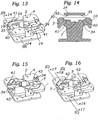
- Fig. 13 discloses recess channels 41 on the front 4 of the bracket body 2 wherein round bumps 35 on the underside of the c-shaped extension 24 guide the rotation of the rotating clip 20.
- Fig. 14 is a cross-section through B-B of Fig. 13 .
- a round bump 35 on the bottom surface of the c-shaped extension 24 fits into the cutout channel 41 of the bracket body 41 and a cutout channel 40 for receiving the free end of the c-shaped extension 24 contains a dimple 34 for receiving the bump 35 on the bottom side of the c-shaped extension 24.
- Fig. 15 discloses a tab 42 on each c-shaped extension 24 extending towards the archwire slot 7. The tab 42 bottom may be smooth or may contain a bump 35.
- Fig. B show a cross-section of Fig. 16 through C-C wherein two dimples, # 1 dimple 43 and # 2 dimple 44, are in the cutout channel 40.
- Fig. 17 A the round bump 35 is in the # 1 dimple 43 which places the flat under side of the c-shaped extension over the archwire 30 that holds the archwire 30 passively.
- Fig. 17 B shows the round bump 35 in the # 2 dimple 44 which places a dimple over the archwire 30 which holds the archwire 30 actively.
- Figs. 18 A and 18 B show Fig. 16 through D-D.
- Fig. 18 A discloses the tab 42 with the smooth underside 26 of the tab 42 above the archwire 30, holding the archwire 30 passively.
- Fig. 18 B shows the tab 42 further advanced over the archwire wherein the underside 26 of the tab 42 has a bump 32 that actively holds the archwire 30.
- Figs. 19 and 20 disclose an index pin 45.
- orthodontic brackets When orthodontic brackets are placed upon teeth they are ideally positioned with the bracket slot a predetermined distance from the incisal edge or occlusal surface of the tooth.
- the horizontal direction of the orthodontic bracket is placed at a right angle to the long axis of the tooth.
- the index pin 45 is a pin vertically attached to the orthodontic bracket that helps visualize the correct long axis placement of the orthodontic bracket during its placement.
- Fig. 19 shows the index pin 45 attached to the self-ligating orthodontic assembly 1 in seats 46 between the left 11 and right 12 tie wings 10.
- Fig. 20 is a cross section through E-E of Fig. 19 .
- a measuring notch 47 shows the position of the underlying archwire slot 7 that is helpful in the vertical positioning of the orthodontic bracket.
- Figs. 21-33 disclose another preferred embodiment of the invention wherein there is a second pair of c-shaped extensions.
- Fig. 21 shows the self-ligating orthodontic bracket assembly 1 in an archwire slot opened position.
- the first c-shaped extensions 49 have a bump 35 on the under side and the second c-shaped extensions have a flat underside 25 a.
- Fig. 22 shows the rotating clip 20 rotated counterclockwise wherein the underside bumps 35 engage and hold the archwire 30 actively.
- Fig. 23 shows the rotating clip 20 rotated clockwise wherein the second c-shaped extensions 48 have a flat undersides 25 a that engage and hold the archwire 30 passively.
- Fig. 21 shows the self-ligating orthodontic bracket assembly 1 in an archwire slot opened position.
- the first c-shaped extensions 49 have a bump 35 on the under side and the second c-shaped extensions have a flat underside 25 a.
- Fig. 22 shows the rotating clip 20 rotated counterclockwise wherein the underside bumps 35
- Elastomeric chains 51 are a series of connected islets made from an elastic material.
- the elastomeric chains 51 are normally used to close spaces between teeth rotate teeth and maintain the lack of spacing between teeth.
- the elastomeric chains 51 normally circle all four bracket wings 10 and secure the archwire 30 in the archwire slot 7. In the present invention, the elastomeric chain 51 does not enclose the archwire.
- the elastomeric chain 51 can be changed without disturbing the archwire 30 or, conversely, the archwire 30 can be changed without disturbing the elastomeric chain 51.
- the invention may include integral hooks for rubber band wear by the patient.
- channels may be placed in the invention to receive removable hooks for rubber band and other attachments.
Landscapes
- Health & Medical Sciences (AREA)
- Oral & Maxillofacial Surgery (AREA)
- Dentistry (AREA)
- Epidemiology (AREA)
- Life Sciences & Earth Sciences (AREA)
- Animal Behavior & Ethology (AREA)
- General Health & Medical Sciences (AREA)
- Public Health (AREA)
- Veterinary Medicine (AREA)
- Dental Tools And Instruments Or Auxiliary Dental Instruments (AREA)
Description
- The present invention is directed to a locking orthodontic bracket that contains a mechanism that rotationally locks an orthodontic archwire within the bracket archwire slot.
- Orthodontic brackets attached to teeth transmit forces, such as produced by an archwire, to move the teeth. Brackets usually contain an archwire slot for reception of the archwire. Orthodontic brackets today are typically bonded to a tooth or welded to an orthodontic band that is cemented to the tooth.
- Brackets commonly use tie wings that project upwardly and downwardly in pairs at the top and bottom of the installed bracket, respectively. These wings permit the archwire to be held within the archwire slot of the bracket by means of a twisted wire (ligature) or an elastomeric o-ring.
Currently there are varieties of brackets that are self-ligating. These self-ligating brackets have taken several forms. -
U.S. Pat. No. 5,094,614 to Wildman, issued Mar. 10, 1992 , discloses a sliding closure that engages the front of the archwire. The closure is recessed from the front or anterior surfaces of the disclosed bracket. These sliding closures are also found inU.S. Pat. No. 2,549,528 to Russell ,U.S. Pat. No. 2,671,964 to Russell et al. and inU.S. Pat. No. 3,131,474 to Johnson . Sliding closures require the archwire also to be recessed within the archwire slot before the closure can be moved over the archwire making it very difficult for the user to visually confirm that the archwire is properly seated within the archwire slot. A conventional bracket has a visual front surface adjacent to the archwire slot making it easy to see if the archwire is seated in the archwire slot. This is not true in the recessed sliding closures. The actual archwire slot surface is beneath the sliding closure. Damon solved this problem inU.S. Pat. Nos. 5,275,557 (Jan. 4, 1994 ),5,429,500 (Jul. 4, 1995 ) and5,466,151 (Nov. 14, 1995 ). - An achievement of these patents is a ligating slide within a bracket that maintains the normal features of protruding tie wings or lugs and a closure in the form of a ligating slide that can complete a continuous tube surrounding the archwire when the closure is in a closed position. This can be achieved in a Siamese or twin bracket configuration without covering or interfering with projecting extensions on the bracket.
- Pletcher,
U.S. Pat. No. 5,322,435 , discloses a locking slide member that is flat and guided by upright slots formed along both sides of the bracket and spanning the archwire slot thereby obscuring visual access to the critical corners of the archwire slots at the side edges of the bracket. Without this visual access being clear, one installing an archwire within a bracket cannot be certain as to proper seating of an archwire within the archwire slot before the slide cover is moved to a closed position. No tie wings or lugs are included in the illustrated bracket forms. - There is a modern esthetic requirement that the brackets be small. A drawback of many self-ligating brackets the locking covers increase the size of the bracket.
- Damon,
US Pat. 6,071,118 , discloses a sliding cover which gives visual access to the archwire slot, but have achieved the enclosure of the sliding cover by thickening the bracket in the gingival area - A sliding spring cover, a hinged locking cover, a rotary sliding cover, a ball type rotatable cover etc. have been disclosed in different U.S. Patents. "Activa" produced by A Company, "Speed" and "Edgelock" produced by Ormco Corporation, and others are typical examples of ligature-less brackets that are commercially available.
- Of all these different locking means a sliding closure has been considered desirable because it can be easily manipulated and it reduces the time required for opening and closing of the arch wire slot during periodic adjustments of the archwire and provides more precise control of the archwire:. There are other means that are more complex and difficult and expensive to manufacture. Springs used as locking means are not strong enough to hold the arch wire into the slot.
-
US 2104192 (Ford ) discloses a locking orthodontic bracket having an orthodontic bracket that contains a rotating clip for locking an orthodontic archwire within the archwire slot of the orthodontic bracket. The orthodontic bracket comprises a body containing a slot to receive an archwire, a base that is attachable to an orthodontic band or directly to a tooth surface, and a central recess on the front surface of the body that extends inwardly towards the base of the bracket. Rotation of the clip in one direction leaves the archwire slot open for the insertion or removal of an archwire and rotation in the opposite direction locks the archwire in the archwire slot. - The present invention is defined in
claim 1. Optional features are defined in the dependent claims. An orthodontic bracket according to the present invention has a rotating clip comprised of a hollow cylindrical body with wings extending from the body. The cylindrical body has a circular base and two opposing vertical walls separated by opposing open sides. The opposing open sides allow for the passage of an archwire through the archwire slot and reduce friction during rotation of the rotating clip. The circular body is fitted and mechanically retained within the recess within the orthodontic bracket. The bracket recess is shaped and sized to receive the hollow circular body. The circular body and bracket recess may contain retentive devices such as circular grooves with matching ridges that also allow rotation of the rotating clip within the bracket recess. The wings extend laterally from the vertical cylindrical body over the surface of the orthodontic bracket. The tubular body is rotatable within the recess of the orthodontic bracket. The rotation moves the wings in a clockwise or counterclockwise motion. The bracket clip insertion hole can be slightly skewed from a perfect circle to allow friction grip when the clip is fully open or fully closed. - In a preferred embodiment, the tips of the wings enclose an orthodontic arch wire within the arch wire slot of the orthodontic bracket when the rotating clip is rotated counterclockwise. A clockwise rotation of the rotating clip opens the arch wire slot for placement or removal of the orthodontic arch wire. The strength transmitted to the wing tip is partially derived from the circular shape of the attached cylindrical body and the intimate fitting of the cylindrical body within the circular recess. The resulting strength is increased allowing the wings to be thinner which is advantageous for patient comfort. The underside of the wing, in one embodiment, has a bump that actively holds the archwire in the slot, as opposed to passively holding the archwire when the underside of the wing is flat. In another embodiment the rotating clip has two sets of wings wherein one pair actively engage the archwire when the rotating clip is rotated in one direction and passively holds the archwire when the rotating clip is rotated in the opposite direction. In another preferred embodiment, the locking clip wing is shaped to enclose most of the arch wire in the archwire slot. In another preferred embodiment, the underside of the locking clip wing contains a bevel to push the arch wire into the arch wire slot. In a further embodiment, the underside of the wing contains bumps for active clip design.
- The bracket wall that retains the rotating clip remains open to self cleanse, reducing calculus build up and stuck moving parts. Tooth brush bristles can access the walls of bracket body. The bracket body design remains the same for both active and passive and active passive designs. The design allows the clinician to go from passive to active to conventional and back at any point in treatment. Height gauges may be used conventionally. The rotating clip does not interfere with anatomical structures, such as gums and other teeth, when in the open position. The rotating clip orthodontic bracket may be comprised of metal, plastic or ceramic or combinations thereof. Equivalent materials may be used. MIM technology can be used for the bracket body wherein retention for the clip is built within and there is a potential to use a breakaway design in MIM for one piece bracket body assembly. The door design will allow only the mesial or distal aspect of wing to be engaged on severely rotated teeth as the wing door can close around one wing while leaving the wire exiting the center of the bracket. The wire can be engaged from both the gingival and the occlusal in door design
- There is an ability to cut out the facial aspect of the bracket leaves latitude to maintain slot integrity while increasing bulk of metal in body and arms, but allowing slot cover part of clip to be thin for springiness (passive/active). It can be designed with reciprocal open//close doors. There are many designs in the clip. The designs may be passive, /active, or active/ active /with the same bracket body which can be a stand-alone twin without the rotating clip. The wings may be altered for the use of non-binding power chains for closing spaces or rotating teeth. Horizontal slots can be added lateral surfaces of the wings. Vertical and horizontal channels may be placed for accessories such as hooks and rotators.
-
-
FIG. 1 is a top perspective view the body of the self-ligating orthodontic bracket; -
FIG. 2 is a side view of the body of the self-ligating orthodontic bracket; -
FIG. 3 is a perspective view of the rotating clip of the self-ligating orthodontic bracket; -
FIG. 4 is a top perspective cutaway view of the body recess of the self-ligating orthodontic bracket; -
FIG. 5 is a top perspective view of the self-ligating orthodontic bracket in an open position; -
FIG. 6 is a top perspective internal view of the rotating clip resting within a cutout view of the body of the self-ligating orthodontic bracket; -
FIG. 7 is a top perspective view of the self-ligating orthodontic bracket with the rotating clip in a closed position; -
FIG. 8 is a top perspective internal view of the self-ligating orthodontic bracket with the rotating clip in a closed position; -
FIG. 9 is a top perspective view of the self-ligating orthodontic bracket with an archwire; -
FIGS. 10A, 10B and 10C are fragmentary side views of the self-ligating orthodontic bracket ofFIG. 9 through A-A with beveled ends of the rotating clip arms; -
FIGS. 11A and 11B are fragmentary side views of the self-ligating orthodontic bracket ofFIG. 9 through A-A with active bumps underside the clip arm end; -
FIGS. 12A and 12B are fragmentary side views of the self-ligating orthodontic bracket ofFIG. 9 through A-A with retentive bumps underside the clip arm end; -
FIG. 13 is a top perspective view of the self-ligating orthodontic bracket with cutout channels; -
FIG. 14 is a cross-sectional view of the self-ligating orthodontic bracket ofFIG. 13 through B-B; -
FIG. 15 is a top perspective view of the self-ligating orthodontic bracket with extension tabs in an open position; -
FIG. 16 is a top perspective view of the self-ligating orthodontic bracket with extension tabs in a closed position; -
FIGS. 17A and 17B are cross-sectional views ofFIG. 16 through C-C; -
FIGS. 18A and 18B are cross-sectional views ofFIG. 16 through D-D; -
FIG. 19 is a top perspective view of the self-ligating orthodontic bracket with an index pin; -
FIG. 20 is a cross-sectional view of the self-ligating orthodontic bracket ofFIG.19 through E-E; -
FIG. 21 is a top perspective view of the self-ligating orthodontic bracket with a second pair of C-shaped extensions, all extensions in the open position; -
FIG. 22 is a top perspective view of the self-ligating orthodontic bracket with a second pair of C-shaped extensions wherein the rotating clip is turned counterclockwise into a closed position; -
FIG. 23 is a top perspective view of the self-ligating orthodontic bracket with a second pair of C-shaped extensions wherein the rotating clip is turned clockwise into a closed position; -
FIG. 24 is top perspective views of a pair of self-ligating orthodontic brackets with notches and attached elastomeric chains; -
FIG. 25 is a top perspective view of the self-ligating orthodontic bracket with a n attachable clip; and -
FIG. 26 is a top perspective view of the self-ligating orthodontic bracket with an attachable clip and anti-rotation notches. - The invention is comprised of a self-ligating
orthodontic bracket assembly 1.Fig. 1 discloses abracket body 2 with aback 3 and afront surface 4. Thebracket body 2 has aleft side 5 andright side 6. Anarchwire slot 7 extends from left 8 to right 9 on thefront surface 4. Attached to thebracket body 2 aretie wings 10 positioned left 11 and right 12. Thetie wings 10 extend outwardly from the top 13 and bottom 14. Thefront surface 4 of thebracket body 2 contains acylindrical recess 15 with acircular wall 16 extending from acircular front 17 towards thebody 2 back 3 ending in a circular floor. Thetie wings 10 fit withinfront surface 4recesses 19 in order to make thetie wings 10 flush with the bracketfront surface 4.Fig. 2 shows thebracket body 2 in cross section.Fig. 3 discloses arotating clip 20 which is attached into thecylindrical recess 15 ofFigs. 1 and 2 . The rotatingclip 20 has acircular base 21 with attached opposingcolumns 22 extending at right angles to thecircular base 21. Between the opposingcolumns 22 are open opposing sides 23. Attached to each opposingcolumn 22 free end is a c-shapedextension 24. The c-shapedextensions 24 each extend horizontally with afree end 25 and anunderside 26. The attached opposingcolumns 22 have an outer circular periphery sized to fit thecircular walls 16 of thecircular recess 15. The circular periphery of thecolumns 22 contains acircular groove 27.Fig. 4 is an enlarged view of thecircular recess 15 disclosing therecess wall 16 with acircular ring 16A which seats into thecircular groove 27 of therotating clip 20. Thecircular ring 16Acircular groove 27 relationship allows the rotatingclip 20 to be retained in thecircular recess 15 and be free to rotate.Fig. 5 discloses the invention in its preferred embodiment. The rotatingclip 20 is inserted in thecylindrical recess 15 of thebracket body 2 wherein thecircular base 21 is seated against thecircular floor 17. The c-shapedextensions 24 extend left 5 and right 6 on the surface of thefront 4 of thebracket body 2. The open opposingsides 23 align with thehorizontal archwire slot 7 allowing an archwire to o travel continuously from theleft end 8 of thearchwire slot 7 to theright end 9 of thearchwire slot 7.Fig. 6 discloses therotating clip 20 as it sits within thebracket body 2. Acircular groove 27 is shown horizontally on the outer surface of the attached opposingcolumn 22.Figs. 5 and 6 show therotating clip 20 in the archwire slot opened position wherein the c-shapedextensions 24 do not enclose thearchwire slot 7. In this position an archwire may be placed and removed from thearchwire slot 7. InFig. 7 the rotatingclip 20 is rotated counterclockwise wherein the c-shapedextension 24 encloses thearchwire slot 7 which would contain an archwire within thearchwire slot 7. This is called the archwire slot closed position.Fig. 8 discloses the details of therotating clip 20 as it rests within thebracket body 2. The open opposingsides 23 between the opposingcolumns 22 allow anarchwire 30 to go between theleft end 8 andright end 9 of thearchwire slot 7. -
Fig. 9 discloses the rotating cliporthodontic bracket 1 with therotating clip 20 in an archwire slot opened position and anarchwire 30 in thearchwire slot 7.Figs. 10A and 10B are cross sections ofFig. 9 through points A-A. The c-shapedextension 24 rests upon thebracket body 2 and has afree end 25 with a beveled leadingedge 28underside 26 wherein the beveled leadingedge 28 facilitates the c-shapedextension 24 sliding over thearchwire 30 as shown inFig. 10B. Fig. 10C is a cross-section of the c-shapedextension 24 with abottom side 14 that is flat 31. InFig. 10B , the flat 31bottom side 14 holds thearchwire 30 passively in thearchwire slot 7.Fig. 11 discloses the cross-section ofFig. 9 wherein the bottom 14 of the c-shapedextension 24 has anactive bump 33 that holds thearchwire 30 actively in thearchwire slot 7 as shown inFig. 11B . InFig. 12A , the bottom 14 of the c-shapedextension 24 has aretentive bump 33 and adimple 34 in thebracket body 2. The rotatingclip 20 is held in a closed position when theretentive bump 33 is seated in the dimple,Fig. 12B .Fig. 13 disclosesrecess channels 41 on thefront 4 of thebracket body 2 wherein round bumps 35 on the underside of the c-shapedextension 24 guide the rotation of therotating clip 20. -
Fig. 14 is a cross-section through B-B ofFig. 13 . Around bump 35 on the bottom surface of the c-shapedextension 24 fits into thecutout channel 41 of thebracket body 41 and acutout channel 40 for receiving the free end of the c-shapedextension 24 contains adimple 34 for receiving thebump 35 on the bottom side of the c-shapedextension 24.Fig. 15 discloses atab 42 on each c-shapedextension 24 extending towards thearchwire slot 7. Thetab 42 bottom may be smooth or may contain abump 35.Figs. 17A and -
Fig. B show a cross-section ofFig. 16 through C-C wherein two dimples, #1dimple 43 and #2dimple 44, are in thecutout channel 40. - In
Fig. 17A , theround bump 35 is in the #1dimple 43 which places the flat under side of the c-shaped extension over thearchwire 30 that holds thearchwire 30 passively.Fig. 17B shows theround bump 35 in the #2dimple 44 which places a dimple over thearchwire 30 which holds thearchwire 30 actively. -
Figs. 18A and 18B showFig. 16 through D-D.Fig. 18A discloses thetab 42 with thesmooth underside 26 of thetab 42 above thearchwire 30, holding thearchwire 30 passively.Fig. 18B shows thetab 42 further advanced over the archwire wherein theunderside 26 of thetab 42 has abump 32 that actively holds thearchwire 30.Figs. 19 and 20 disclose anindex pin 45. When orthodontic brackets are placed upon teeth they are ideally positioned with the bracket slot a predetermined distance from the incisal edge or occlusal surface of the tooth. In addition, the horizontal direction of the orthodontic bracket is placed at a right angle to the long axis of the tooth. Theindex pin 45 is a pin vertically attached to the orthodontic bracket that helps visualize the correct long axis placement of the orthodontic bracket during its placement.Fig. 19 shows theindex pin 45 attached to the self-ligatingorthodontic assembly 1 inseats 46 between the left 11 and right 12tie wings 10.Fig.20 is a cross section through E-E ofFig. 19 . In addition, a measuringnotch 47 shows the position of theunderlying archwire slot 7 that is helpful in the vertical positioning of the orthodontic bracket. -
Figs. 21-33 disclose another preferred embodiment of the invention wherein there is a second pair of c-shaped extensions.Fig.21 shows the self-ligatingorthodontic bracket assembly 1 in an archwire slot opened position. The first c-shapedextensions 49 have abump 35 on the under side and the second c-shaped extensions have aflat underside 25a.Fig. 22 shows therotating clip 20 rotated counterclockwise wherein the underside bumps 35 engage and hold thearchwire 30 actively.Fig. 23 shows therotating clip 20 rotated clockwise wherein the second c-shapedextensions 48 have aflat undersides 25a that engage and hold thearchwire 30 passively.Fig. 24 discloses a modification of the bracket wings wherein the upper and lower left wings have horizontal notches extending to the body center from the left of the bracket and the upper and lower right wings havehorizontal notches 50 extending to thecenter 4 of thebracket body 2, thenotches 50 allow attachment of orthodonticelastomeric power chains 51 to theupper wings 13 only or to thelower wings 14 only.Elastomeric chains 51 are a series of connected islets made from an elastic material. Theelastomeric chains 51 are normally used to close spaces between teeth rotate teeth and maintain the lack of spacing between teeth. Theelastomeric chains 51 normally circle all fourbracket wings 10 and secure thearchwire 30 in thearchwire slot 7. In the present invention, theelastomeric chain 51 does not enclose the archwire. Theelastomeric chain 51 can be changed without disturbing the archwire 30 or, conversely, thearchwire 30 can be changed without disturbing theelastomeric chain 51. - The invention may include integral hooks for rubber band wear by the patient. In the alternative, channels may be placed in the invention to receive removable hooks for rubber band and other attachments.
- The invention, as described, is not limited to the specific embodiments described as these are preferred embodiments. The invention is claimed in any of its modifications within the proper scope of its claims.
Claims (14)
- A rotating clip orthodontic bracket (1) comprising:an orthodontic bracket comprising a body (2), the body having a back (3), a front (4) with a center, left (5) and right (6) sides, a top (13) and a bottom (14), the body front containing an archwire slot (7) extending horizontally from left (8) to right (9) and shaped to receive an orthodontic archwire (30) with right and left ends, left (11) and right (12) tie wings (10) at the top and bottom of the body for tie wires or elastomeric ties (51) for securing an archwire within the archwire slot;a cylindrical recess (15) with walls (16) in the center of the body front of the orthodontic bracket wherein the cylindrical recess is open on the body front and extends towards the body back wherein the cylindrical recess ends with a circular floor; anda rotating clip (20) within the cylindrical recess for securing orthodontic archwires comprised of a circular base (21), two attached opposing columns (22) separated by open opposing sides (23) which allow the passage of an archwire through the archwire slot, each column supporting a c-shaped extension (24) with a free end (25) and an underside (26) facing the bracket body front (4) wherein the circular base is fitted to the wall adjacent to the circular floor, the opposing columns are fitted to the cylindrical recess walls and the c-shaped extensions extend on the bracket front in opposing directions, the clip is fitted in the cylindrical recess, wherein the clip is rotatable in one rotational direction to an archwire slot opened position in which the bracket slot is open allowing the insertion and removal of an archwire and is rotatable in an opposite rotational direction to an archwire slot closed position in which the c-shaped extensions are configured to retain the archwire within the archwire slot at the right and left ends of the archwire slot.
- The rotating clip orthodontic bracket (1) of claim 1 further comprising top and bottom index pin notches (46) in the center of the front (4) of the bracket between the left and right tie wings (11, 12), the top and bottom index pin notches (46) being configured to receive an index pin (45) with a measuring notch (47) for guiding the placement of the orthodontic bracket on a tooth.
- The rotating clip orthodontic bracket (1) of claim 1 wherein the undersides (26) of the c-shaped extensions (24) at the free ends (25) each contain a bump (35) projecting downwards towards the front (4) of the body (2) of the orthodontic bracket, the front of the body contains dimples (34) shaped to receive the respective bumps, the dimples (34) are placed to receive the respective bumps (35) and lock the c-shaped extension in the archwire slot closed position and lock the c-shaped extension in the archwire slot opened position.
- The rotating clip orthodontic bracket clip of claim 1 wherein the free ends (25) of the c-shaped extensions (24) each have a surface facing the front (4) of the body (2) of the orthodontic bracket, this surface is beveled tapered (28) towards the c-shaped extension free end (25) which facilitates sliding the c-shaped extension free end (25) over an orthodontic archwire (30) that has been placed in the archwire slot (7).
- The rotating clip orthodontic bracket (1) of claim 1 wherein the c-shaped extensions (24) have flat (31) undersides (26) which enclose the archwire passively in the archwire slot (7) when the rotating clip (20) is rotated to the archwire slot closed position.
- The rotating clip orthodontic bracket (1) of claim 1 wherein the c-shaped extensions (24) have round bumps (35) extruding from their undersides (26) near their free ends (25) which press down and hold the archwire (30) actively in the archwire slot when the rotating clip (20) is rotated to the archwire slot closed position.
- The rotating clip orthodontic bracket (1) of claim 1 wherein the bracket body face has cutouts (40) adjacent to the archwire slot (7) shaped to receive the free ends (25) of the c-shaped extensions (24) which have underside bumps (35) in their free ends and middles and a channel (41) on the bracket body face under each c-shaped extension to guide the middle underside bumps during the rotation of the rotating clip (20).
- The rotating clip orthodontic bracket (1) of claim 1 wherein there are four c-shaped extensions (24), two c-shaped opposing extensions (48) with flat undersides (25a) which enclose the archwire (30) passively when the rotating clip (20) is rotated in a first direction to a first archwire slot closed position and two c-shaped extensions (49) with underside bumps (35) which enclose the archwire actively in the archwire slot (7) when the rotating clip is rotated in a direction opposite to the first direction to a second archwire slot closed position.
- The rotating clip orthodontic bracket (1) of claim 1 wherein the c-shaped extensions (24) each have a middle which contain an extension tab (42) which projects towards the archwire slot (7), the extension tab encloses the archwire (30) when the rotating clip (20) is in the archwire slot closed position thus increasing the closure of the archwire in the archwire slot.
- The rotating clip orthodontic bracket (1) of claim 1 wherein the top and bottom left wings (11) have horizontal notches (50) extending to the body center from the left of the bracket and the top and bottom right wings (12) have horizontal notches (50) extending to the body center from the right of the bracket, the notches being configured to allow attachment of orthodontic elastomeric power chains (51) to the top wings only or to the bottom wings only which prevents the elastomeric chains from contacting and binding the archwire (30) and allows the archwire to be placed or removed without removing the elastomeric chain.
- The rotating clip orthodontic bracket (1) of claim 1 wherein there are upper and lower index pin notches (46) positioned between adjacent tie wings (10) to receive an index pin (45) with a horizontal measuring notch (47) for positioning the orthodontic bracket upon a tooth
- The rotating clip orthodontic bracket (1) of claim 1 wherein the cylindrical wall (16) has a circular ring (16A), and the attached columns (22) of the rotating clip (20) have a circular groove (27), wherein when the circular ring (16A) is seated in the circular groove (27) the rotating clip is allowed to rotate without being unseated from the cylindrical recess (15).
- The rotating clip orthodontic bracket (1) of claim 1 which is comprised of a variety of materials such as metal, plastic and ceramic and the rotating clip (20) has an attachable clip (55) comprised of a variety of materials such as metal, plastic and ceramic and decorative forms such as a variety of colors, glow-in-the-dark and LED lights which may be activated by the patient tapping their teeth together.
- The rotating clip orthodontic bracket (1) of claim 1 wherein the bracket body front (4) has cutout channels (40) adjacent to the archwire slot (7) shaped to receive the free ends (25) of the c-shaped extensions (24) in a closed position.
Applications Claiming Priority (2)
| Application Number | Priority Date | Filing Date | Title |
|---|---|---|---|
| US12/592,078 US8162660B2 (en) | 2009-11-20 | 2009-11-20 | Rotating clip orthodontic bracket |
| PCT/US2010/001823 WO2011062603A1 (en) | 2009-11-20 | 2010-06-25 | Rotating clip orthodontic bracket |
Publications (3)
| Publication Number | Publication Date |
|---|---|
| EP2501330A1 EP2501330A1 (en) | 2012-09-26 |
| EP2501330A4 EP2501330A4 (en) | 2014-12-24 |
| EP2501330B1 true EP2501330B1 (en) | 2018-08-15 |
Family
ID=44059884
Family Applications (1)
| Application Number | Title | Priority Date | Filing Date |
|---|---|---|---|
| EP10831890.8A Not-in-force EP2501330B1 (en) | 2009-11-20 | 2010-06-25 | Rotating clip orthodontic bracket |
Country Status (4)
| Country | Link |
|---|---|
| US (3) | US8162660B2 (en) |
| EP (1) | EP2501330B1 (en) |
| JP (1) | JP5716171B2 (en) |
| WO (1) | WO2011062603A1 (en) |
Families Citing this family (32)
| Publication number | Priority date | Publication date | Assignee | Title |
|---|---|---|---|---|
| US7695277B1 (en) | 2004-10-28 | 2010-04-13 | Rmo, Inc. | Orthodontic bracket with frangible cover mechanism |
| US20110287378A1 (en) * | 2002-10-29 | 2011-11-24 | Rmo, Inc. | Orthodontic appliance with encoded information formed in the base |
| US7704072B2 (en) | 2006-04-19 | 2010-04-27 | Ormco Corporation | Orthodontic bracket |
| US9554875B2 (en) | 2006-09-07 | 2017-01-31 | Rmo, Inc. | Method for producing a customized orthodontic appliance |
| WO2008031060A2 (en) | 2006-09-07 | 2008-03-13 | Rmo, Inc. | Reduced-friction buccal tube and method of use |
| US8979528B2 (en) | 2006-09-07 | 2015-03-17 | Rmo, Inc. | Customized orthodontic appliance method and system |
| WO2010107567A1 (en) | 2009-03-16 | 2010-09-23 | Rmo, Inc. | Orthodontic bracket having an archwire channel and archwire retaining mechanism |
| US11219507B2 (en) | 2009-03-16 | 2022-01-11 | Orthoamerica Holdings, Llc | Customized orthodontic appliance and method |
| US8162660B2 (en) | 2009-11-20 | 2012-04-24 | Robert T Rudman | Rotating clip orthodontic bracket |
| USD660435S1 (en) * | 2011-05-13 | 2012-05-22 | Rmo, Inc. | Orthodontic bracket |
| US20120315593A1 (en) * | 2011-06-13 | 2012-12-13 | Asociacion Metropolitana Para La Educacion | Adjustable orthodontic bracket |
| USD847349S1 (en) | 2011-09-22 | 2019-04-30 | Rmo, Inc. | Orthodontic lock with flange |
| US9220241B2 (en) * | 2012-05-15 | 2015-12-29 | Radio Systems Corporation | Collar strap attachment mechanism |
| US8550814B1 (en) | 2012-08-16 | 2013-10-08 | Monte Collins | Multi-component orthodontic bracket assembly |
| USD726318S1 (en) | 2013-01-17 | 2015-04-07 | Rmo, Inc. | Dental instrument for a self-ligating orthodontic clip |
| US9532853B2 (en) | 2013-03-15 | 2017-01-03 | Ormco Corporation | Self-ligating orthodontic bracket and method of using the same |
| RU2664158C2 (en) * | 2013-06-14 | 2018-08-15 | Ормко Корпорейшн | Self-ligating orthodontic bracket with rotatable closure member |
| USD721811S1 (en) | 2013-10-29 | 2015-01-27 | Rmo, Inc. | Orthodontic bracket |
| US9943383B2 (en) | 2014-12-19 | 2018-04-17 | Ormco Corporation | Biased pivoting slide orthodontic bracket |
| US20160175072A1 (en) | 2014-12-19 | 2016-06-23 | Ormco Corporation | Self-ligating orthodontic bracket with rotatable closure member |
| US20170000588A1 (en) * | 2015-07-01 | 2017-01-05 | Ormco Corporation | Self-ligating orthodontic bracket with an external rotatable closure member |
| US10085824B2 (en) | 2015-10-30 | 2018-10-02 | Ortho Organizers, Inc. | Self ligating orthodontic bracket |
| US11731566B2 (en) | 2016-03-04 | 2023-08-22 | Joseph E. Kovarik | Snowboard carrier for a vehicle |
| US10239465B2 (en) | 2016-03-04 | 2019-03-26 | Joseph E. Kovarik | Method and system for carrying a bicycle on a vehicle |
| DE102018115871A1 (en) * | 2018-06-29 | 2020-01-02 | Bernhard Förster Gmbh | Self-ligating bracket for orthodontics |
| US11273013B2 (en) | 2020-05-05 | 2022-03-15 | Ortho Solutions, LC | Twist-lock orthodontic post |
| USD940878S1 (en) | 2020-05-05 | 2022-01-11 | Ortho Solutions, LC | Orthodontic post |
| US11324573B2 (en) | 2020-07-03 | 2022-05-10 | Aadvance Technologies, Llc | Orthodontic device |
| US11202692B1 (en) | 2020-11-30 | 2021-12-21 | King Abdulaziz University | Hamad bi-slot orthodontic bracket |
| CN113729995B (en) * | 2021-09-14 | 2025-01-28 | 北京大学口腔医学院 | Self-ligating brackets, double-wing adjustable brackets and dental braces |
| CN116211503B (en) * | 2021-12-06 | 2025-07-25 | 广州欧欧医疗科技有限责任公司 | Orthodontic appliance and orthodontic system |
| WO2023161952A1 (en) * | 2022-02-26 | 2023-08-31 | Benoy Mathew | Spherical dome shaped lingual orthodontic bracket with a shape memory alloy based self-ligation lock |
Family Cites Families (80)
| Publication number | Priority date | Publication date | Assignee | Title |
|---|---|---|---|---|
| US1240731A (en) * | 1916-12-29 | 1917-09-18 | John James Kinehan | Orthodontic appliance. |
| US2011575A (en) | 1933-01-28 | 1935-08-20 | James W Ford | Orthodontic appliance |
| US2104192A (en) * | 1935-08-19 | 1938-01-04 | James W Ford | Orthodontic appliance |
| US2959856A (en) * | 1959-09-15 | 1960-11-15 | Orthodontic Specialties Inc | Orthodontic device |
| US3084437A (en) | 1960-04-07 | 1963-04-09 | Neger Milton | Orthodontic appliance |
| US3158934A (en) | 1961-02-21 | 1964-12-01 | Waldman David | Orthodontic appliances |
| US3238619A (en) | 1963-04-29 | 1966-03-08 | Rocky Mouutain Dental Products | Arch wire locking device for orthodontic bracket |
| US3469315A (en) | 1967-02-08 | 1969-09-30 | Patrick C Russ | Orthodontic appliance |
| US3633277A (en) | 1970-06-24 | 1972-01-11 | Myron Reichel | Orthodontic uprighting springs for tipping and uprighting teeth |
| US3793730A (en) | 1972-05-05 | 1974-02-26 | Tp Labor Inc | Lock spring pin appliance |
| CH613110A5 (en) | 1976-05-20 | 1979-09-14 | Foerster Bernhard Fa | |
| US4077126A (en) | 1976-07-06 | 1978-03-07 | Pletcher Erwin Carroll | Orthodontic bracket |
| DE2744283C3 (en) * | 1977-10-01 | 1981-09-17 | Bernhard Förster GmbH, 7530 Pforzheim | Tensioning device for orthodontic archwires |
| CH619611A5 (en) * | 1977-01-17 | 1980-10-15 | Foerster Bernhard Fa | |
| US4198753A (en) | 1977-03-26 | 1980-04-22 | Firma Bernhard Forster | Dental fixing element |
| US4664626A (en) | 1985-03-19 | 1987-05-12 | Kesling Peter C | System for automatically preventing overtipping and/or overuprighting in the begg technique |
| US4597739A (en) | 1985-05-21 | 1986-07-01 | Farel Rosenberg | Tow element bracket system for true straight wire orthodontics |
| US4712999A (en) * | 1986-09-10 | 1987-12-15 | Farel Rosenberg | Convertible, self-ligating, archwire positioning orthodontic bracket |
| US4859179A (en) | 1986-11-26 | 1989-08-22 | Tp Orthodontics, Inc. | Edgewise bracket with Sved shaped slot and control means |
| US4698017A (en) | 1986-12-10 | 1987-10-06 | Hanson Gustaf H | Orthodontic brackets |
| GB2200847B (en) | 1987-01-29 | 1991-01-02 | Robert Andrew Parker | Orthodontic bracket |
| US4917602A (en) | 1988-09-12 | 1990-04-17 | Broussard Garfford J | Adjustable orthodontic bracket assembly |
| US5474445A (en) * | 1994-03-07 | 1995-12-12 | John Voudouris | Self-engaging twin edge-wise orthodontic bracket with pivotal latch |
| US5857850A (en) * | 1994-03-07 | 1999-01-12 | Voudouris; John C. | Orthodontic appliance |
| US6257883B1 (en) | 1994-03-07 | 2001-07-10 | John C. Voudouris | Orthodontic bracket |
| JPH08112293A (en) * | 1994-10-18 | 1996-05-07 | Tomy Kk | Orthodontic bracket |
| US5607301A (en) * | 1994-11-01 | 1997-03-04 | Lancer Orthodontics | Orthodontic bracket and method of mounting |
| US5685711A (en) * | 1995-12-06 | 1997-11-11 | Hanson; G. Herbert | Self-ligating orthodontic brackets |
| US5823771A (en) | 1997-05-27 | 1998-10-20 | Nord; Philip J. | Vertical straight wire orthodontic aplliance having interchangeable anchor components |
| US6071118A (en) * | 1998-02-17 | 2000-06-06 | Damon Family Limited Partnership | Self-ligating orthodontic bracket |
| US6071119A (en) | 1998-12-22 | 2000-06-06 | 3M Innovative Properties Company | Dual mode self-ligating orthodontic bracket |
| JP4444410B2 (en) | 1999-10-08 | 2010-03-31 | トミー株式会社 | Orthodontic brackets and tools for orthodontic brackets |
| DE10011596B4 (en) | 2000-03-10 | 2007-12-27 | Norbert Dr. Abels | Orthodontic bracket |
| US6247923B1 (en) * | 2000-05-24 | 2001-06-19 | Nikhil Shankarlal Vashi | Self-locking orthodontic bracket |
| US6506049B2 (en) | 2000-09-20 | 2003-01-14 | Augusta Developments Inc. | Orthodontic brackets and convertible buccal tubes |
| BR0116897A (en) | 2001-02-15 | 2004-06-15 | Norbert Abels | Self-ligating orthodontic brackets including a prone binding cover towards an open or closed position |
| WO2002064051A1 (en) | 2001-02-15 | 2002-08-22 | Norbert Abels | Self-ligating orthodontic brackets having a rigid bracket base and deformable ligation cover |
| JP4659991B2 (en) | 2001-02-28 | 2011-03-30 | トミー株式会社 | Orthodontic bracket |
| JP4411573B2 (en) | 2001-08-24 | 2010-02-10 | トミー株式会社 | Orthodontic bracket |
| US6932597B2 (en) | 2001-09-12 | 2005-08-23 | Norbert Abels | Self-ligating orthodontic brackets including a metal ligation cover hingedly connected to a bracket base |
| JP3886796B2 (en) * | 2001-12-17 | 2007-02-28 | 独立行政法人科学技術振興機構 | Orthodontic bracket |
| US6682345B2 (en) | 2002-03-25 | 2004-01-27 | Tp Orthodontics, Inc. | Orthodontic bracket |
| US6846178B2 (en) | 2002-10-29 | 2005-01-25 | Rmo, Inc. | Orthodontic bracket base apparatus and method of manufacture |
| US7959437B2 (en) | 2002-10-29 | 2011-06-14 | Rmo, Inc. | Orthodontic appliance with encoded information formed in the base |
| US7695277B1 (en) | 2004-10-28 | 2010-04-13 | Rmo, Inc. | Orthodontic bracket with frangible cover mechanism |
| US20110287378A1 (en) | 2002-10-29 | 2011-11-24 | Rmo, Inc. | Orthodontic appliance with encoded information formed in the base |
| US20060051721A1 (en) * | 2002-11-26 | 2006-03-09 | Luis Carriere Lluch | Improvements to orthodontic supports applicable to teeth |
| US7621743B2 (en) | 2002-11-26 | 2009-11-24 | Orthodontic Research And Development, S.L. | Orthodontic bracket |
| JP4233949B2 (en) | 2002-12-09 | 2009-03-04 | トミー株式会社 | Orthodontic bracket and grip release tool |
| EP1452148B1 (en) | 2003-02-27 | 2009-04-15 | Heiser, Wolfgang, Dr. med. | Bracket |
| US6960081B2 (en) | 2003-03-04 | 2005-11-01 | Norbert Abels | Orthodontic brackets with elongate film hinge |
| US6866505B2 (en) * | 2003-05-14 | 2005-03-15 | Self-engaging orthodontic bracket | |
| US20050019718A1 (en) * | 2003-07-22 | 2005-01-27 | Hanson G. Herbert | Orthodontic devices for use with arch wires |
| TWI304633B (en) | 2003-08-25 | 2008-12-21 | Promos Technologies Inc | Semiconductor device and fabricating method thereof |
| US7186114B2 (en) | 2004-03-30 | 2007-03-06 | Navarro Carlos F | Self-ligating lingual orthodontic bracket |
| US7234935B2 (en) | 2004-04-29 | 2007-06-26 | Norbert Abels | Orthodontic bracket system comprising multiple brackets having multiple aligned slots |
| US7094052B2 (en) | 2004-04-30 | 2006-08-22 | Norbert Abels | Orthodontic brackets with temporarily visible marking features |
| US7063531B2 (en) | 2004-07-16 | 2006-06-20 | Rolf Maijer | Orthodontic bracket system |
| DE102004056167A1 (en) | 2004-11-18 | 2006-06-01 | Bernhard Förster Gmbh | Self-ligating bracket for orthodontics |
| US7214057B2 (en) | 2005-03-10 | 2007-05-08 | Ceramic Sciences Incorporated | Self-ligating orthodontic bracket |
| US7335020B2 (en) | 2005-04-08 | 2008-02-26 | Lancer Orthodontics | Low profile self-ligating bracket assembly and method of use |
| US20070009849A1 (en) * | 2005-07-11 | 2007-01-11 | Wool Arthur L | Self-locking orthodontic bracket |
| JP4505815B2 (en) | 2005-07-20 | 2010-07-21 | チカミミルテック株式会社 | Orthodontic appliance |
| EP1942823A4 (en) * | 2005-09-28 | 2012-02-29 | American Orthodontics Corp | AUTOLIGATORY BRACKET SYSTEM |
| US7674110B2 (en) * | 2006-03-23 | 2010-03-09 | Ormco Corporation | Low profile self-ligating orthodontic brackets and methods of using such orthodontic brackets |
| US20070243497A1 (en) * | 2006-04-18 | 2007-10-18 | Ceramic Sciences Incorporated | Orthodontic bracket assembly |
| US7585171B2 (en) * | 2006-05-04 | 2009-09-08 | World Class Technology Corporation | Orthodontic bracket with rotary ligating cover |
| US7780443B2 (en) | 2006-05-04 | 2010-08-24 | World Class Technology Corporation | Self-ligating bracket with rotary cover |
| US20070269763A1 (en) * | 2006-05-18 | 2007-11-22 | Claus Schendell-Groling | Orthodontic bracket |
| DE102006027130B4 (en) | 2006-06-02 | 2012-04-26 | Bernhard Förster Gmbh | Self-ligating bracket and its use for orthodontics |
| US7306458B1 (en) | 2006-07-14 | 2007-12-11 | Yu-Hua Lu | Adjustable orthodontic bracket |
| JP5000954B2 (en) * | 2006-09-07 | 2012-08-15 | 哲也 下田 | Orthodontic bracket |
| CN201085695Y (en) | 2007-07-16 | 2008-07-16 | 秦德川 | Novel torque former |
| US7845940B2 (en) * | 2007-11-02 | 2010-12-07 | Mark Minium | Orthodontic apparatus with self-ligating bracket and locking device |
| US8246348B2 (en) * | 2007-12-27 | 2012-08-21 | Wolfgang Heiser | Self-ligating orthodontic bracket |
| US7963768B2 (en) * | 2008-09-05 | 2011-06-21 | Jack Keith Hilliard | Self-ligating orthodontic bracket assembly |
| US20100151403A1 (en) * | 2008-12-12 | 2010-06-17 | Tuneberg Lee H | Bracket with improved arch wire slot liner |
| DE102009029834A1 (en) * | 2009-06-17 | 2010-12-23 | Bernhard Förster Gmbh | Series of brackets for orthodontics |
| US20110081622A1 (en) | 2009-10-05 | 2011-04-07 | Cameron Mashouf | Self-ligating bracket with universal application |
| US8162660B2 (en) | 2009-11-20 | 2012-04-24 | Robert T Rudman | Rotating clip orthodontic bracket |
-
2009
- 2009-11-20 US US12/592,078 patent/US8162660B2/en not_active Ceased
-
2010
- 2010-06-25 JP JP2012539863A patent/JP5716171B2/en not_active Expired - Fee Related
- 2010-06-25 EP EP10831890.8A patent/EP2501330B1/en not_active Not-in-force
- 2010-06-25 WO PCT/US2010/001823 patent/WO2011062603A1/en not_active Ceased
-
2014
- 2014-04-22 US US14/258,944 patent/USRE45904E1/en not_active Expired - Fee Related
-
2016
- 2016-02-19 US US15/048,519 patent/USRE46646E1/en not_active Expired - Fee Related
Non-Patent Citations (1)
| Title |
|---|
| None * |
Also Published As
| Publication number | Publication date |
|---|---|
| JP5716171B2 (en) | 2015-05-13 |
| US20110123942A1 (en) | 2011-05-26 |
| USRE46646E1 (en) | 2017-12-26 |
| US8162660B2 (en) | 2012-04-24 |
| USRE45904E1 (en) | 2016-03-01 |
| JP2013511327A (en) | 2013-04-04 |
| WO2011062603A1 (en) | 2011-05-26 |
| EP2501330A4 (en) | 2014-12-24 |
| EP2501330A1 (en) | 2012-09-26 |
Similar Documents
| Publication | Publication Date | Title |
|---|---|---|
| USRE46646E1 (en) | Rotating clip orthodontic bracket | |
| US12048609B2 (en) | Self-ligating orthodontic bracket | |
| CN101662995B (en) | Self-ligating bracket with rotary cover | |
| US9744004B2 (en) | Orthodontic bracket | |
| AU2006202089B2 (en) | Improved orthodontic bracket | |
| EP1679048B1 (en) | Self-ligating orthodontic bracket | |
| US8246347B2 (en) | Low profile self-ligating orthodontic brackets and methods of using such orthodontic brackets | |
| KR101307190B1 (en) | Orthodontic bracket with rotary ligating cover | |
| US20190090987A1 (en) | Orthodontic bracket | |
| US20090155734A1 (en) | Orthodontic bracket | |
| US20100203463A1 (en) | Self-ligating orthodontic bracket | |
| US20110081622A1 (en) | Self-ligating bracket with universal application | |
| CN108430381A (en) | self-locking bracket | |
| EP0955937A1 (en) | Alignable, self-ligating orthodontic brackets | |
| HK1141432B (en) | Self-ligating bracket with rotary cover |
Legal Events
| Date | Code | Title | Description |
|---|---|---|---|
| PUAI | Public reference made under article 153(3) epc to a published international application that has entered the european phase |
Free format text: ORIGINAL CODE: 0009012 |
|
| 17P | Request for examination filed |
Effective date: 20120613 |
|
| AK | Designated contracting states |
Kind code of ref document: A1 Designated state(s): AL AT BE BG CH CY CZ DE DK EE ES FI FR GB GR HR HU IE IS IT LI LT LU LV MC MK MT NL NO PL PT RO SE SI SK SM TR |
|
| RAP1 | Party data changed (applicant data changed or rights of an application transferred) |
Owner name: ORMCO CORPORATION |
|
| RIN1 | Information on inventor provided before grant (corrected) |
Inventor name: RUDMAN, ROBERT T. |
|
| TPAC | Observations filed by third parties |
Free format text: ORIGINAL CODE: EPIDOSNTIPA |
|
| REG | Reference to a national code |
Ref country code: DE Ref legal event code: R079 Ref document number: 602010052846 Country of ref document: DE Free format text: PREVIOUS MAIN CLASS: A61D0005000000 Ipc: A61C0007280000 |
|
| A4 | Supplementary search report drawn up and despatched |
Effective date: 20141124 |
|
| RIC1 | Information provided on ipc code assigned before grant |
Ipc: A61C 7/28 20060101AFI20141118BHEP |
|
| STAA | Information on the status of an ep patent application or granted ep patent |
Free format text: STATUS: EXAMINATION IS IN PROGRESS |
|
| 17Q | First examination report despatched |
Effective date: 20161117 |
|
| GRAP | Despatch of communication of intention to grant a patent |
Free format text: ORIGINAL CODE: EPIDOSNIGR1 |
|
| STAA | Information on the status of an ep patent application or granted ep patent |
Free format text: STATUS: GRANT OF PATENT IS INTENDED |
|
| INTG | Intention to grant announced |
Effective date: 20180308 |
|
| GRAS | Grant fee paid |
Free format text: ORIGINAL CODE: EPIDOSNIGR3 |
|
| GRAA | (expected) grant |
Free format text: ORIGINAL CODE: 0009210 |
|
| STAA | Information on the status of an ep patent application or granted ep patent |
Free format text: STATUS: THE PATENT HAS BEEN GRANTED |
|
| AK | Designated contracting states |
Kind code of ref document: B1 Designated state(s): AL AT BE BG CH CY CZ DE DK EE ES FI FR GB GR HR HU IE IS IT LI LT LU LV MC MK MT NL NO PL PT RO SE SI SK SM TR |
|
| REG | Reference to a national code |
Ref country code: CH Ref legal event code: EP Ref country code: GB Ref legal event code: FG4D Ref country code: AT Ref legal event code: REF Ref document number: 1028852 Country of ref document: AT Kind code of ref document: T Effective date: 20180815 |
|
| REG | Reference to a national code |
Ref country code: IE Ref legal event code: FG4D |
|
| REG | Reference to a national code |
Ref country code: DE Ref legal event code: R096 Ref document number: 602010052846 Country of ref document: DE |
|
| REG | Reference to a national code |
Ref country code: NL Ref legal event code: MP Effective date: 20180815 |
|
| REG | Reference to a national code |
Ref country code: LT Ref legal event code: MG4D |
|
| REG | Reference to a national code |
Ref country code: AT Ref legal event code: MK05 Ref document number: 1028852 Country of ref document: AT Kind code of ref document: T Effective date: 20180815 |
|
| PG25 | Lapsed in a contracting state [announced via postgrant information from national office to epo] |
Ref country code: LT Free format text: LAPSE BECAUSE OF FAILURE TO SUBMIT A TRANSLATION OF THE DESCRIPTION OR TO PAY THE FEE WITHIN THE PRESCRIBED TIME-LIMIT Effective date: 20180815 Ref country code: FI Free format text: LAPSE BECAUSE OF FAILURE TO SUBMIT A TRANSLATION OF THE DESCRIPTION OR TO PAY THE FEE WITHIN THE PRESCRIBED TIME-LIMIT Effective date: 20180815 Ref country code: NL Free format text: LAPSE BECAUSE OF FAILURE TO SUBMIT A TRANSLATION OF THE DESCRIPTION OR TO PAY THE FEE WITHIN THE PRESCRIBED TIME-LIMIT Effective date: 20180815 Ref country code: SE Free format text: LAPSE BECAUSE OF FAILURE TO SUBMIT A TRANSLATION OF THE DESCRIPTION OR TO PAY THE FEE WITHIN THE PRESCRIBED TIME-LIMIT Effective date: 20180815 Ref country code: BG Free format text: LAPSE BECAUSE OF FAILURE TO SUBMIT A TRANSLATION OF THE DESCRIPTION OR TO PAY THE FEE WITHIN THE PRESCRIBED TIME-LIMIT Effective date: 20181115 Ref country code: GR Free format text: LAPSE BECAUSE OF FAILURE TO SUBMIT A TRANSLATION OF THE DESCRIPTION OR TO PAY THE FEE WITHIN THE PRESCRIBED TIME-LIMIT Effective date: 20181116 Ref country code: IS Free format text: LAPSE BECAUSE OF FAILURE TO SUBMIT A TRANSLATION OF THE DESCRIPTION OR TO PAY THE FEE WITHIN THE PRESCRIBED TIME-LIMIT Effective date: 20181215 Ref country code: NO Free format text: LAPSE BECAUSE OF FAILURE TO SUBMIT A TRANSLATION OF THE DESCRIPTION OR TO PAY THE FEE WITHIN THE PRESCRIBED TIME-LIMIT Effective date: 20181115 Ref country code: AT Free format text: LAPSE BECAUSE OF FAILURE TO SUBMIT A TRANSLATION OF THE DESCRIPTION OR TO PAY THE FEE WITHIN THE PRESCRIBED TIME-LIMIT Effective date: 20180815 |
|
| PG25 | Lapsed in a contracting state [announced via postgrant information from national office to epo] |
Ref country code: HR Free format text: LAPSE BECAUSE OF FAILURE TO SUBMIT A TRANSLATION OF THE DESCRIPTION OR TO PAY THE FEE WITHIN THE PRESCRIBED TIME-LIMIT Effective date: 20180815 Ref country code: AL Free format text: LAPSE BECAUSE OF FAILURE TO SUBMIT A TRANSLATION OF THE DESCRIPTION OR TO PAY THE FEE WITHIN THE PRESCRIBED TIME-LIMIT Effective date: 20180815 Ref country code: LV Free format text: LAPSE BECAUSE OF FAILURE TO SUBMIT A TRANSLATION OF THE DESCRIPTION OR TO PAY THE FEE WITHIN THE PRESCRIBED TIME-LIMIT Effective date: 20180815 |
|
| PG25 | Lapsed in a contracting state [announced via postgrant information from national office to epo] |
Ref country code: CZ Free format text: LAPSE BECAUSE OF FAILURE TO SUBMIT A TRANSLATION OF THE DESCRIPTION OR TO PAY THE FEE WITHIN THE PRESCRIBED TIME-LIMIT Effective date: 20180815 Ref country code: RO Free format text: LAPSE BECAUSE OF FAILURE TO SUBMIT A TRANSLATION OF THE DESCRIPTION OR TO PAY THE FEE WITHIN THE PRESCRIBED TIME-LIMIT Effective date: 20180815 Ref country code: IT Free format text: LAPSE BECAUSE OF FAILURE TO SUBMIT A TRANSLATION OF THE DESCRIPTION OR TO PAY THE FEE WITHIN THE PRESCRIBED TIME-LIMIT Effective date: 20180815 Ref country code: EE Free format text: LAPSE BECAUSE OF FAILURE TO SUBMIT A TRANSLATION OF THE DESCRIPTION OR TO PAY THE FEE WITHIN THE PRESCRIBED TIME-LIMIT Effective date: 20180815 Ref country code: PL Free format text: LAPSE BECAUSE OF FAILURE TO SUBMIT A TRANSLATION OF THE DESCRIPTION OR TO PAY THE FEE WITHIN THE PRESCRIBED TIME-LIMIT Effective date: 20180815 Ref country code: ES Free format text: LAPSE BECAUSE OF FAILURE TO SUBMIT A TRANSLATION OF THE DESCRIPTION OR TO PAY THE FEE WITHIN THE PRESCRIBED TIME-LIMIT Effective date: 20180815 |
|
| REG | Reference to a national code |
Ref country code: DE Ref legal event code: R097 Ref document number: 602010052846 Country of ref document: DE |
|
| PG25 | Lapsed in a contracting state [announced via postgrant information from national office to epo] |
Ref country code: SK Free format text: LAPSE BECAUSE OF FAILURE TO SUBMIT A TRANSLATION OF THE DESCRIPTION OR TO PAY THE FEE WITHIN THE PRESCRIBED TIME-LIMIT Effective date: 20180815 Ref country code: DK Free format text: LAPSE BECAUSE OF FAILURE TO SUBMIT A TRANSLATION OF THE DESCRIPTION OR TO PAY THE FEE WITHIN THE PRESCRIBED TIME-LIMIT Effective date: 20180815 Ref country code: SM Free format text: LAPSE BECAUSE OF FAILURE TO SUBMIT A TRANSLATION OF THE DESCRIPTION OR TO PAY THE FEE WITHIN THE PRESCRIBED TIME-LIMIT Effective date: 20180815 |
|
| PLBE | No opposition filed within time limit |
Free format text: ORIGINAL CODE: 0009261 |
|
| STAA | Information on the status of an ep patent application or granted ep patent |
Free format text: STATUS: NO OPPOSITION FILED WITHIN TIME LIMIT |
|
| REG | Reference to a national code |
Ref country code: DE Ref legal event code: R082 Ref document number: 602010052846 Country of ref document: DE Representative=s name: HASELTINE LAKE KEMPNER LLP, DE Ref country code: DE Ref legal event code: R081 Ref document number: 602010052846 Country of ref document: DE Owner name: RUDMAN, ROBERT T., DENVER, US Free format text: FORMER OWNER: ORMCO CORP., ORANGE, CALIF., US Ref country code: DE Ref legal event code: R082 Ref document number: 602010052846 Country of ref document: DE Representative=s name: HL KEMPNER PATENTANWALT, RECHTSANWALT, SOLICIT, DE |
|
| 26N | No opposition filed |
Effective date: 20190516 |
|
| PG25 | Lapsed in a contracting state [announced via postgrant information from national office to epo] |
Ref country code: SI Free format text: LAPSE BECAUSE OF FAILURE TO SUBMIT A TRANSLATION OF THE DESCRIPTION OR TO PAY THE FEE WITHIN THE PRESCRIBED TIME-LIMIT Effective date: 20180815 |
|
| REG | Reference to a national code |
Ref country code: GB Ref legal event code: 732E Free format text: REGISTERED BETWEEN 20190808 AND 20190814 |
|
| PG25 | Lapsed in a contracting state [announced via postgrant information from national office to epo] |
Ref country code: MC Free format text: LAPSE BECAUSE OF FAILURE TO SUBMIT A TRANSLATION OF THE DESCRIPTION OR TO PAY THE FEE WITHIN THE PRESCRIBED TIME-LIMIT Effective date: 20180815 |
|
| REG | Reference to a national code |
Ref country code: CH Ref legal event code: PL |
|
| REG | Reference to a national code |
Ref country code: BE Ref legal event code: MM Effective date: 20190630 |
|
| PG25 | Lapsed in a contracting state [announced via postgrant information from national office to epo] |
Ref country code: TR Free format text: LAPSE BECAUSE OF FAILURE TO SUBMIT A TRANSLATION OF THE DESCRIPTION OR TO PAY THE FEE WITHIN THE PRESCRIBED TIME-LIMIT Effective date: 20180815 |
|
| PG25 | Lapsed in a contracting state [announced via postgrant information from national office to epo] |
Ref country code: IE Free format text: LAPSE BECAUSE OF NON-PAYMENT OF DUE FEES Effective date: 20190625 |
|
| PG25 | Lapsed in a contracting state [announced via postgrant information from national office to epo] |
Ref country code: CH Free format text: LAPSE BECAUSE OF NON-PAYMENT OF DUE FEES Effective date: 20190630 Ref country code: LI Free format text: LAPSE BECAUSE OF NON-PAYMENT OF DUE FEES Effective date: 20190630 Ref country code: LU Free format text: LAPSE BECAUSE OF NON-PAYMENT OF DUE FEES Effective date: 20190625 Ref country code: BE Free format text: LAPSE BECAUSE OF NON-PAYMENT OF DUE FEES Effective date: 20190630 |
|
| PG25 | Lapsed in a contracting state [announced via postgrant information from national office to epo] |
Ref country code: PT Free format text: LAPSE BECAUSE OF FAILURE TO SUBMIT A TRANSLATION OF THE DESCRIPTION OR TO PAY THE FEE WITHIN THE PRESCRIBED TIME-LIMIT Effective date: 20181215 |
|
| REG | Reference to a national code |
Ref country code: DE Ref legal event code: R082 Ref document number: 602010052846 Country of ref document: DE Representative=s name: HL KEMPNER PATENTANWAELTE, SOLICITORS (ENGLAND, DE Ref country code: DE Ref legal event code: R082 Ref document number: 602010052846 Country of ref document: DE Representative=s name: HL KEMPNER PATENTANWALT, RECHTSANWALT, SOLICIT, DE |
|
| PG25 | Lapsed in a contracting state [announced via postgrant information from national office to epo] |
Ref country code: CY Free format text: LAPSE BECAUSE OF FAILURE TO SUBMIT A TRANSLATION OF THE DESCRIPTION OR TO PAY THE FEE WITHIN THE PRESCRIBED TIME-LIMIT Effective date: 20180815 |
|
| PG25 | Lapsed in a contracting state [announced via postgrant information from national office to epo] |
Ref country code: HU Free format text: LAPSE BECAUSE OF FAILURE TO SUBMIT A TRANSLATION OF THE DESCRIPTION OR TO PAY THE FEE WITHIN THE PRESCRIBED TIME-LIMIT; INVALID AB INITIO Effective date: 20100625 Ref country code: MT Free format text: LAPSE BECAUSE OF FAILURE TO SUBMIT A TRANSLATION OF THE DESCRIPTION OR TO PAY THE FEE WITHIN THE PRESCRIBED TIME-LIMIT Effective date: 20180815 |
|
| PG25 | Lapsed in a contracting state [announced via postgrant information from national office to epo] |
Ref country code: MK Free format text: LAPSE BECAUSE OF FAILURE TO SUBMIT A TRANSLATION OF THE DESCRIPTION OR TO PAY THE FEE WITHIN THE PRESCRIBED TIME-LIMIT Effective date: 20180815 |
|
| P01 | Opt-out of the competence of the unified patent court (upc) registered |
Effective date: 20230530 |
|
| PGFP | Annual fee paid to national office [announced via postgrant information from national office to epo] |
Ref country code: FR Payment date: 20230626 Year of fee payment: 14 Ref country code: DE Payment date: 20230626 Year of fee payment: 14 |
|
| PGFP | Annual fee paid to national office [announced via postgrant information from national office to epo] |
Ref country code: GB Payment date: 20230627 Year of fee payment: 14 |
|
| REG | Reference to a national code |
Ref country code: DE Ref legal event code: R119 Ref document number: 602010052846 Country of ref document: DE |
|
| GBPC | Gb: european patent ceased through non-payment of renewal fee |
Effective date: 20240625 |
|
| PG25 | Lapsed in a contracting state [announced via postgrant information from national office to epo] |
Ref country code: DE Free format text: LAPSE BECAUSE OF NON-PAYMENT OF DUE FEES Effective date: 20250101 |
|
| PG25 | Lapsed in a contracting state [announced via postgrant information from national office to epo] |
Ref country code: FR Free format text: LAPSE BECAUSE OF NON-PAYMENT OF DUE FEES Effective date: 20240630 |
|
| PG25 | Lapsed in a contracting state [announced via postgrant information from national office to epo] |
Ref country code: GB Free format text: LAPSE BECAUSE OF NON-PAYMENT OF DUE FEES Effective date: 20240625 |