EP2501210A2 - Power distribution unit and method of distributing high density power - Google Patents
Power distribution unit and method of distributing high density power Download PDFInfo
- Publication number
- EP2501210A2 EP2501210A2 EP20120159698 EP12159698A EP2501210A2 EP 2501210 A2 EP2501210 A2 EP 2501210A2 EP 20120159698 EP20120159698 EP 20120159698 EP 12159698 A EP12159698 A EP 12159698A EP 2501210 A2 EP2501210 A2 EP 2501210A2
- Authority
- EP
- European Patent Office
- Prior art keywords
- solid state
- state power
- power
- power module
- module
- Prior art date
- Legal status (The legal status is an assumption and is not a legal conclusion. Google has not performed a legal analysis and makes no representation as to the accuracy of the status listed.)
- Ceased
Links
- 238000000034 method Methods 0.000 title claims description 15
- 239000007787 solid Substances 0.000 claims abstract description 69
- 238000004806 packaging method and process Methods 0.000 claims description 10
- 238000004891 communication Methods 0.000 claims description 8
- 230000004224 protection Effects 0.000 description 8
- 238000010586 diagram Methods 0.000 description 4
- 230000004075 alteration Effects 0.000 description 3
- 238000010438 heat treatment Methods 0.000 description 1
- 238000009434 installation Methods 0.000 description 1
- 238000012544 monitoring process Methods 0.000 description 1
- 230000008707 rearrangement Effects 0.000 description 1
- 239000000523 sample Substances 0.000 description 1
- 238000006467 substitution reaction Methods 0.000 description 1
Images


Classifications
-
- H—ELECTRICITY
- H05—ELECTRIC TECHNIQUES NOT OTHERWISE PROVIDED FOR
- H05K—PRINTED CIRCUITS; CASINGS OR CONSTRUCTIONAL DETAILS OF ELECTRIC APPARATUS; MANUFACTURE OF ASSEMBLAGES OF ELECTRICAL COMPONENTS
- H05K7/00—Constructional details common to different types of electric apparatus
- H05K7/14—Mounting supporting structure in casing or on frame or rack
- H05K7/1438—Back panels or connecting means therefor; Terminals; Coding means to avoid wrong insertion
- H05K7/1457—Power distribution arrangements
Definitions
- the present invention relates to power distribution systems, and more particularly to high density power systems and methods of high density power distribution.
- An example of such an application is a vehicle, such as an aircraft.
- the limited space available for system components drives the requirement for high density power distribution.
- the power distribution system must be sufficiently compact, while still being adequately configured to distribute power to typically several loads.
- the loads include various types of protection against over-current, over and under-frequency, arc fault, and ground fault, to name a few potential sources of disruptions to load functionality.
- Circuit breaker panels are sized to attempt to fit into the space constrained areas, which are often unavailable during flight and are difficult to access on the ground, in the case of an aircraft.
- a power distribution unit includes a first solid state power module comprising a first plurality of solid state power controllers, where the first solid state power module comprises a first set of power characteristics. Also included is a second solid state power module comprising a second plurality of solid state power controllers. The second solid state power module comprises a second set of power characteristics. Also, the first solid state power module and the second solid state power module are interchangeably coupled to a first location of a common chassis.
- a method of distributing high density power includes packaging a first plurality of solid state power controllers to form a first solid state power module, where the first solid state power module comprises a first set of power characteristics. Also included is packaging a second plurality of solid state power controllers to form a second solid state power module, where the second solid state power module comprises a second set of power characteristics. Further included is selectively placing one of the first solid state power module and the second solid state power module within a first position of a chassis, where the first solid state power module and the second solid state power module are interchangeable. Yet further included is controlling one of the first solid state power module and the second solid state power module with a control interface.
- FIG. 1 schematically illustrates a power distribution unit having a logic section and a power section
- FIG. 2 illustrates a block diagram of a plurality of solid state power modules
- FIG. 3 illustrates a block diagram of a power block arranged in a first configuration
- FIG. 4 illustrates a block diagram of the power block arranged in a second configuration
- FIG. 5 is a flow diagram illustrating a method of distributing high density power.
- a power distribution unit is generally schematically illustrated with reference numeral 10.
- the power distribution unit 10 may be employed in a variety of applications, such as an aircraft or another vehicle (not illustrated), for example.
- the vehicle includes a plurality of powered vehicle systems 12, 14, 16.
- the power distribution unit 10 provides power to the powered vehicle systems 12, 14, 16 and is supplied power by a power supply 18.
- the power distribution unit 10 comprises a logic section 20 and a power section 22, with the power section 22 being made up, at least in part, by one or more solid state power modules (SSPMs) 24, each having a plurality of solid state power controllers (SSPCs) 26.
- the SSPCs 26 employ transistors to provide a switching function and use electronics to provide a circuit breaker function to protect wiring associated with the power vehicle systems 12, 14, 16.
- the SSPMs 24, based on the composition of SSPCs 26, provide a variety of system protections including, but not limited to, integrated current sensing, over-current, and over-temperature protection, to name simply a few illustrative examples.
- the SSPCs 26 function as arc fault protection, ground fault protection, and when used as part of a larger protection network, provide differential current protection.
- Each of the SSPCs 26 includes a power supply (not shown) that facilitates operation of the SSPCs 26.
- the SSPMs 24 include a first side and a second side and the SSPCs 26 are configured to mount to either the first side or the second side of the SSPMs 24, thereby providing a more compact packaging of the SSPCs 26 and making more efficient use of limited space provided for the power distribution unit 10.
- the plurality of SSPCs 26 that are mounted to, or packaged as, each SSPM 24 comprise a specific set of power characteristics for each SSPM 24.
- the power characteristics vary between distinct SSPMs 24 and provide various functionalities, depending on the assembly of SSPCs 26.
- the logic section 20 senses current at various locations proximate the SSPCs 26 to determine if appropriate functionality is occurring. In the event of a disruptive condition, the SSPCs 26 may be switched to an "off" condition.
- the logic section 20 and the SSPCs 26 may include various components that are configured to receive and transmit data related to operation of the SSPCs 26, among other things. Such components may include microcontrollers and communications interfaces.
- one or more SSPMs 24 are placed within a common chassis 30 and a common backplane 32.
- SSPMs 24 having a variety of power characteristics are available for assembly and can be interchangeably used at various locations within the power distribution unit 10 ( FIG. 1 ), and more specifically within the power section 22 ( FIG. 1 ).
- the ability to selectively configure the SSPMs 24 having various power characteristics provides assembling flexibility and a more diverse set of power characteristics to employ in the power distribution unit 10. It is to be appreciated that the SSPMs 24 are reusable clusters that may be installed in various configurations on the common chassis 30 and the common backplane 32.
- first SSPM family 40 and a second SSPM family 42 are illustrated and it is shown that the first SSPM family 40 and the second SSPM family 42 each include distinct SSPMs 24 that are interchangeable, such that a first SSPM 24 could be positioned in replacement of a second SSPM 24, if an alteration of power characteristics for a particular application was desired.
- a consistent communication control interface is employed. By providing consistent communication control, regardless of the specific SSPM 24 arrangement, greater assembly flexibility is available without requiring rearrangement or alteration of the control interface. It is to be understood that the illustrated embodiments include two SSPMs, however, any number of SSPMs may be employed to comprise the SSPM family.
- the SSPM families 40, 42 may be part of a power block that provides functionality within the power distribution unit 10.
- the term "power block” conceptually refers to hardware structure that functionally monitors and protects at least one load, but typically a plurality of load circuits. Nominally, this may include solid state power controllers (SSPCs), control logic, processing logic, internal communications busses, and power supplies to power various control elements.
- the protected load is any device that consumes power. This can be as simple as a resistive heating element in an air data probe, a light bulb disposed in the application, such as an aircraft, or as complex as a motor controller used to drive a hydraulic pump.
- the SSPCs 26 By monitoring and controlling operating conditions that loads and power distribution units are encountering, the SSPCs 26 have the ability to quickly and flexibly switch power sources and limit or disrupt power to selected loads in the event of harmful operating conditions.
- the power distribution unit 10 also includes a combination of remote data concentration modules and remote power control modules that are not in direct contact with the power distribution unit 10, but are in operable communication with the power distribution unit.
- the remote data concentration modules and the remote power control modules are configured to facilitate remote control of the various circuit protections that the power distribution unit 10 provides. This is particularly useful in applications such as the instant case, where the spaces in which the power distribution unit 10 is disposed may be difficult to access, or even completely inaccessible during operation.
- the power distribution unit 10 has been previously described and specific components need not be described in further detail.
- the method includes packaging a first plurality of SSPCs 50 to form a first SSPM.
- the specific SSPCs packaged to form the first SSPM provides a first set of power characteristics.
- packaging a second plurality of SSPCs 52 to form a second SSPM provides a second set of power characteristics. Based on the application of use, at least one of the first SSPM and the second SSPM is selectively placed 54 within the chassis to form a power block.
- the method includes controlling 56 a SSPM family with a control interface that provides consistent communication control. Additionally, the SSPM may be remotely controlled 58 with a remote data module and/or a remote power control module.
- the previously described packaging scheme for the power distribution unit 10 adequately addresses tight spatial constraints imposed in certain applications, while also providing a consistent communication control with the control interface that communicates with the power block.
Landscapes
- Engineering & Computer Science (AREA)
- Power Engineering (AREA)
- Microelectronics & Electronic Packaging (AREA)
- Remote Monitoring And Control Of Power-Distribution Networks (AREA)
- Charge And Discharge Circuits For Batteries Or The Like (AREA)
Abstract
Description
- The present invention relates to power distribution systems, and more particularly to high density power systems and methods of high density power distribution.
- Applications requiring power distribution often have severe space constraints for power distribution system components. An example of such an application is a vehicle, such as an aircraft. The limited space available for system components drives the requirement for high density power distribution. The power distribution system must be sufficiently compact, while still being adequately configured to distribute power to typically several loads. The loads include various types of protection against over-current, over and under-frequency, arc fault, and ground fault, to name a few potential sources of disruptions to load functionality. Circuit breaker panels are sized to attempt to fit into the space constrained areas, which are often unavailable during flight and are difficult to access on the ground, in the case of an aircraft.
- According to one embodiment, a power distribution unit includes a first solid state power module comprising a first plurality of solid state power controllers, where the first solid state power module comprises a first set of power characteristics. Also included is a second solid state power module comprising a second plurality of solid state power controllers. The second solid state power module comprises a second set of power characteristics. Also, the first solid state power module and the second solid state power module are interchangeably coupled to a first location of a common chassis.
- According to another embodiment, a method of distributing high density power is provided. The method includes packaging a first plurality of solid state power controllers to form a first solid state power module, where the first solid state power module comprises a first set of power characteristics. Also included is packaging a second plurality of solid state power controllers to form a second solid state power module, where the second solid state power module comprises a second set of power characteristics. Further included is selectively placing one of the first solid state power module and the second solid state power module within a first position of a chassis, where the first solid state power module and the second solid state power module are interchangeable. Yet further included is controlling one of the first solid state power module and the second solid state power module with a control interface.
- The subject matter which is regarded as the invention is particularly pointed out and distinctly claimed in the claims at the conclusion of the specification. The foregoing and other features and advantages of the invention are apparent from the following detailed description taken in conjunction with the accompanying drawings in which:
-
FIG. 1 schematically illustrates a power distribution unit having a logic section and a power section; -
FIG. 2 illustrates a block diagram of a plurality of solid state power modules; -
FIG. 3 illustrates a block diagram of a power block arranged in a first configuration; -
FIG. 4 illustrates a block diagram of the power block arranged in a second configuration; and -
FIG. 5 is a flow diagram illustrating a method of distributing high density power. - Referring to
FIG. 1 , a power distribution unit is generally schematically illustrated withreference numeral 10. Thepower distribution unit 10 may be employed in a variety of applications, such as an aircraft or another vehicle (not illustrated), for example. The vehicle includes a plurality of poweredvehicle systems power distribution unit 10 provides power to the poweredvehicle systems power supply 18. - The
power distribution unit 10 comprises alogic section 20 and apower section 22, with thepower section 22 being made up, at least in part, by one or more solid state power modules (SSPMs) 24, each having a plurality of solid state power controllers (SSPCs) 26. The SSPCs 26 employ transistors to provide a switching function and use electronics to provide a circuit breaker function to protect wiring associated with thepower vehicle systems SSPCs 26, provide a variety of system protections including, but not limited to, integrated current sensing, over-current, and over-temperature protection, to name simply a few illustrative examples. Individually, the SSPCs 26 function as arc fault protection, ground fault protection, and when used as part of a larger protection network, provide differential current protection. Each of theSSPCs 26 includes a power supply (not shown) that facilitates operation of theSSPCs 26. The SSPMs 24 include a first side and a second side and the SSPCs 26 are configured to mount to either the first side or the second side of theSSPMs 24, thereby providing a more compact packaging of theSSPCs 26 and making more efficient use of limited space provided for thepower distribution unit 10. The plurality ofSSPCs 26 that are mounted to, or packaged as, each SSPM 24 comprise a specific set of power characteristics for each SSPM 24. The power characteristics vary betweendistinct SSPMs 24 and provide various functionalities, depending on the assembly ofSSPCs 26. In operation, thelogic section 20 senses current at various locations proximate theSSPCs 26 to determine if appropriate functionality is occurring. In the event of a disruptive condition, theSSPCs 26 may be switched to an "off" condition. Specifically, thelogic section 20 and theSSPCs 26 may include various components that are configured to receive and transmit data related to operation of theSSPCs 26, among other things. Such components may include microcontrollers and communications interfaces. - Referring to
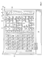
FIG. 2 , one ormore SSPMs 24 are placed within acommon chassis 30 and acommon backplane 32. As described above, SSPMs 24 having a variety of power characteristics are available for assembly and can be interchangeably used at various locations within the power distribution unit 10 (FIG. 1 ), and more specifically within the power section 22 (FIG. 1 ). The ability to selectively configure theSSPMs 24 having various power characteristics provides assembling flexibility and a more diverse set of power characteristics to employ in thepower distribution unit 10. It is to be appreciated that the SSPMs 24 are reusable clusters that may be installed in various configurations on thecommon chassis 30 and thecommon backplane 32. - Referring to
FIGS. 3 and 4 , afirst SSPM family 40 and asecond SSPM family 42 are illustrated and it is shown that thefirst SSPM family 40 and thesecond SSPM family 42 each includedistinct SSPMs 24 that are interchangeable, such that afirst SSPM 24 could be positioned in replacement of asecond SSPM 24, if an alteration of power characteristics for a particular application was desired. Irrespective of the particular installation configuration of theSSPMs 24, a consistent communication control interface is employed. By providing consistent communication control, regardless of thespecific SSPM 24 arrangement, greater assembly flexibility is available without requiring rearrangement or alteration of the control interface. It is to be understood that the illustrated embodiments include two SSPMs, however, any number of SSPMs may be employed to comprise the SSPM family. - The SSPM
families power distribution unit 10. The term "power block" conceptually refers to hardware structure that functionally monitors and protects at least one load, but typically a plurality of load circuits. Nominally, this may include solid state power controllers (SSPCs), control logic, processing logic, internal communications busses, and power supplies to power various control elements. The protected load is any device that consumes power. This can be as simple as a resistive heating element in an air data probe, a light bulb disposed in the application, such as an aircraft, or as complex as a motor controller used to drive a hydraulic pump. By monitoring and controlling operating conditions that loads and power distribution units are encountering, theSSPCs 26 have the ability to quickly and flexibly switch power sources and limit or disrupt power to selected loads in the event of harmful operating conditions. - The
power distribution unit 10 also includes a combination of remote data concentration modules and remote power control modules that are not in direct contact with thepower distribution unit 10, but are in operable communication with the power distribution unit. The remote data concentration modules and the remote power control modules are configured to facilitate remote control of the various circuit protections that thepower distribution unit 10 provides. This is particularly useful in applications such as the instant case, where the spaces in which thepower distribution unit 10 is disposed may be difficult to access, or even completely inaccessible during operation. - Referring to
FIG. 5 , a method of distributing high density power is illustrated. Thepower distribution unit 10 has been previously described and specific components need not be described in further detail. The method includes packaging a first plurality ofSSPCs 50 to form a first SSPM. As described above, the specific SSPCs packaged to form the first SSPM provides a first set of power characteristics. Similarly, packaging a second plurality ofSSPCs 52 to form a second SSPM provides a second set of power characteristics. Based on the application of use, at least one of the first SSPM and the second SSPM is selectively placed 54 within the chassis to form a power block. Irrespective of whether the first SSPM or the second SSPM is placed on a particular location of the chassis, the method includes controlling 56 a SSPM family with a control interface that provides consistent communication control. Additionally, the SSPM may be remotely controlled 58 with a remote data module and/or a remote power control module. - Accordingly, the previously described packaging scheme for the
power distribution unit 10 adequately addresses tight spatial constraints imposed in certain applications, while also providing a consistent communication control with the control interface that communicates with the power block. - While the invention has been described in detail in connection with only a limited number of embodiments, it should be readily understood that the invention is not limited to such disclosed embodiments. Rather, the invention can be modified to incorporate any number of variations, alterations, substitutions or equivalent arrangements not heretofore described, but which are commensurate with the scope of the invention, which is defined by the claims. Additionally, while various embodiments of the invention have been described, it is to be understood that aspects of the invention may include only some of the described embodiments. Accordingly, the invention is not to be seen as limited by the foregoing description, but is only limited by the scope of the appended claims.
Claims (15)
- A power distribution unit comprising:a first solid state power module comprising a first plurality of solid state power controllers, wherein the first solid state power module comprises a first set of power characteristics; anda second solid state power module comprising a second plurality of solid state power controllers, wherein the second solid state power module comprises a second set of power characteristics, wherein the first solid state power module and the second solid state power module are interchangeably coupled to a first location of a common chassis.
- The power distribution unit of claim 1, further comprising a control interface in operable communication with the power distribution unit, wherein the control interface is configured to control the first solid state power module and the second solid state power module.
- The power distribution unit of claim 2, further comprising a plurality of remote data concentration modules and a plurality of remote power control modules.
- The power distribution unit of claim 3, wherein the control interface is configured to control the plurality of remote data concentration modules and the plurality of remote power control modules.
- The power distribution unit of claim 1, 2, 3 or 4, wherein the solid state power module comprises a common backplane.
- The power distribution unit of claim 5, wherein the first solid state power module includes a first side having at least one first side mounting component and a second side having at least one second side mounting component, wherein the first plurality of solid state power controllers are configured to mount to the first side and the second side.
- The power distribution unit of claim 6, wherein the first solid state power module is mounted to the common chassis and the common backplane.
- The power distribution unit of any preceding claim, further comprising a plurality of common chassis locations; preferably
wherein a plurality of interchangeable solid state power modules are interchangeably coupled to the plurality of common chassis locations. - A method of distributing high density power comprising:packaging a first plurality of solid state power controllers to form a first solid state power module, wherein the first solid state power module comprises a first set of power characteristics;packaging a second plurality of solid state power controllers to form a second solid state power module, wherein the second solid state power module comprises a second set of power characteristics;selectively placing one of the first solid state power module and the second solid state power module within a first position of a chassis, wherein the first solid state power module and the second solid state power module are interchangeable; andcontrolling one of the first solid state power module and the second solid state power module with a control interface.
- The method of claim 9, wherein packaging the first plurality of solid state power controllers further comprises mounting a first solid state power controller to a first side of the first solid state power module and a second solid state power controller to a second side of the second solid state power module.
- The method of claim 9 or 10, further comprising interchanging at least one alternate solid state power controllers with at least one of the first plurality of solid state power controllers.
- The method of claim 9, 10 or 11, further comprising selectively packaging a plurality of solid state power modules to form a solid state power module family, wherein the solid state power module family comprises a plurality of alternative configurations.
- The method of claim 12, further comprising controlling the power block with the control interface.
- The method of any of claims 9 to 13, further comprising integrating at least one remote data module and at least one remote power control module.
- The method of claim 14, further comprising controlling the at least one remote data module and the at least one remote power control module with the control interface.
Applications Claiming Priority (1)
| Application Number | Priority Date | Filing Date | Title |
|---|---|---|---|
| US201161453249P | 2011-03-16 | 2011-03-16 |
Publications (2)
| Publication Number | Publication Date |
|---|---|
| EP2501210A2 true EP2501210A2 (en) | 2012-09-19 |
| EP2501210A3 EP2501210A3 (en) | 2017-04-26 |
Family
ID=46027548
Family Applications (1)
| Application Number | Title | Priority Date | Filing Date |
|---|---|---|---|
| EP12159698.5A Ceased EP2501210A3 (en) | 2011-03-16 | 2012-03-15 | Power distribution unit and method of distributing high density power |
Country Status (2)
| Country | Link |
|---|---|
| US (1) | US9271423B2 (en) |
| EP (1) | EP2501210A3 (en) |
Families Citing this family (8)
| Publication number | Priority date | Publication date | Assignee | Title |
|---|---|---|---|---|
| TWI547052B (en) | 2015-12-08 | 2016-08-21 | 台達電子工業股份有限公司 | Power distribution unit and fault detecting method |
| US10202088B2 (en) | 2016-01-15 | 2019-02-12 | Hamilton Sundstrand Corporation | Combined remote sensing, processing, and solid state power control system |
| GB2568720B (en) | 2017-11-24 | 2020-05-13 | Ge Aviat Systems Ltd | Method and apparatus for initializing a power distribution circuit |
| GB2568721B (en) | 2017-11-24 | 2020-05-13 | Ge Aviat Systems Ltd | Method and apparatus for initalizing a power distribution circuit |
| GB2568725B (en) | 2017-11-24 | 2021-08-18 | Ge Aviat Systems Ltd | Method and apparatus for initializing a controller module |
| US10524377B2 (en) | 2018-01-31 | 2019-12-31 | Eaton Intelligent Power Limited | Power distribution unit with interior busbars |
| US10826782B2 (en) | 2018-10-30 | 2020-11-03 | Ge Aviation Systems Limited | Method and apparatus for initializing a controller module |
| US12617298B2 (en) | 2022-08-15 | 2026-05-05 | Hamilton Sundstrand Corporation | Power district architecture for a vehicle |
Citations (2)
| Publication number | Priority date | Publication date | Assignee | Title |
|---|---|---|---|---|
| US20030133319A1 (en) * | 2002-01-16 | 2003-07-17 | Radosevich Lawrence D. | Compact fluid cooled power converter supporting multiple circuit boards |
| US6856045B1 (en) * | 2002-01-29 | 2005-02-15 | Hamilton Sundstrand Corporation | Power distribution assembly with redundant architecture |
Family Cites Families (12)
| Publication number | Priority date | Publication date | Assignee | Title |
|---|---|---|---|---|
| US3300686A (en) * | 1963-07-30 | 1967-01-24 | Ibm | Compatible packaging of miniaturized circuit modules |
| US3721890A (en) * | 1972-03-27 | 1973-03-20 | Electric Regulator Corp | Power supply for a.c. and d.c. drive |
| JP2001188817A (en) * | 1999-12-28 | 2001-07-10 | Toshiba Corp | Logic synthesis apparatus, logic synthesis method, computer-readable recording medium storing logic synthesis program, and circuit manufacturing method |
| US6344912B1 (en) * | 2000-05-26 | 2002-02-05 | Versatile Optical Networks | Hybrid and scalable opto-electronic processing in a wavelength-division multiplexed system |
| US7389411B2 (en) * | 2003-08-29 | 2008-06-17 | Sun Microsystems, Inc. | Secure transfer of host identities |
| US7665071B1 (en) * | 2003-12-11 | 2010-02-16 | Sun Microsystems, Inc. | Management object model for performing management of a computer system |
| US7583507B2 (en) * | 2006-03-31 | 2009-09-01 | Spectra Logic Corporation | High density array system having multiple storage units with active movable media drawers |
| US7492604B2 (en) * | 2006-04-21 | 2009-02-17 | Motorola, Inc. | Electronic module interconnection apparatus |
| US7805204B2 (en) * | 2007-03-21 | 2010-09-28 | Honeywell International Inc. | Integrated electrical power distribution system using common building blocks |
| US20090020608A1 (en) * | 2007-04-05 | 2009-01-22 | Bennett Jon C R | Universal memory socket and card and system for using the same |
| US20100195289A1 (en) * | 2009-01-30 | 2010-08-05 | Dialogic Corporation | Modular front-panel connectivity on standard architecture server appliances |
| US8738268B2 (en) * | 2011-03-10 | 2014-05-27 | The Boeing Company | Vehicle electrical power management and distribution |
-
2012
- 2012-03-15 US US13/421,233 patent/US9271423B2/en not_active Expired - Fee Related
- 2012-03-15 EP EP12159698.5A patent/EP2501210A3/en not_active Ceased
Patent Citations (2)
| Publication number | Priority date | Publication date | Assignee | Title |
|---|---|---|---|---|
| US20030133319A1 (en) * | 2002-01-16 | 2003-07-17 | Radosevich Lawrence D. | Compact fluid cooled power converter supporting multiple circuit boards |
| US6856045B1 (en) * | 2002-01-29 | 2005-02-15 | Hamilton Sundstrand Corporation | Power distribution assembly with redundant architecture |
Also Published As
| Publication number | Publication date |
|---|---|
| US20120235496A1 (en) | 2012-09-20 |
| US9271423B2 (en) | 2016-02-23 |
| EP2501210A3 (en) | 2017-04-26 |
Similar Documents
| Publication | Publication Date | Title |
|---|---|---|
| US9271423B2 (en) | Power distribution unit and method of distributing high density power | |
| US8704574B2 (en) | SSPC distribution system and control strategy | |
| US10721834B2 (en) | Method and apparatus for modular power distribution | |
| US6737763B2 (en) | Intelligent load sharing with power limiting scheme for multiple power supplies connected to a common load | |
| US9270113B2 (en) | Power distribution cabinet | |
| US6661119B2 (en) | System and method for distributed power supply supporting high currents with redundancy | |
| US20160322802A1 (en) | Modular power distribution system and methods | |
| EP2442425B1 (en) | Electrical power control system for a vehicle. | |
| EP3018788B1 (en) | Low voltage dc distribution system for charging passenger devices | |
| RU2434789C2 (en) | System and method of electric power distribution inside aircraft | |
| CA2740239A1 (en) | Power switching arrangement | |
| EP2679486A1 (en) | Heated floor panel for an aircraft and aircraft having a heated floor panel | |
| US20070271403A1 (en) | Method and apparatus for hot swap of line replaceable modules for AC and DC electric power systems | |
| US20150148995A1 (en) | Aircraft Power Management System And Method For Managing Power Supply In An Aircraft | |
| KR20150063393A (en) | System and method for supplying power to surveillance video cameras and protection cases for such video cameras | |
| US7671490B2 (en) | System for high reliability power distribution within an electronics equipment cabinet | |
| US7928607B2 (en) | Aircraft power system and apparatus for supplying power to an aircraft electrical system | |
| EP2860837A1 (en) | Virtual circuit breaker | |
| US20140117774A1 (en) | Power feed entry circuit for telecommunication applications | |
| EP3972194B1 (en) | Redundant power supply unit | |
| CA3042983C (en) | Heated electrical distribution system | |
| JP2015050814A (en) | Power supply unit and power supply device using the same | |
| KR20140083812A (en) | Protection Switch of Power Distribution of Vehicles Battery |
Legal Events
| Date | Code | Title | Description |
|---|---|---|---|
| PUAI | Public reference made under article 153(3) epc to a published international application that has entered the european phase |
Free format text: ORIGINAL CODE: 0009012 |
|
| AK | Designated contracting states |
Kind code of ref document: A2 Designated state(s): AL AT BE BG CH CY CZ DE DK EE ES FI FR GB GR HR HU IE IS IT LI LT LU LV MC MK MT NL NO PL PT RO RS SE SI SK SM TR |
|
| AX | Request for extension of the european patent |
Extension state: BA ME |
|
| PUAL | Search report despatched |
Free format text: ORIGINAL CODE: 0009013 |
|
| AK | Designated contracting states |
Kind code of ref document: A3 Designated state(s): AL AT BE BG CH CY CZ DE DK EE ES FI FR GB GR HR HU IE IS IT LI LT LU LV MC MK MT NL NO PL PT RO RS SE SI SK SM TR |
|
| AX | Request for extension of the european patent |
Extension state: BA ME |
|
| RIC1 | Information provided on ipc code assigned before grant |
Ipc: H05K 7/14 20060101AFI20170320BHEP |
|
| STAA | Information on the status of an ep patent application or granted ep patent |
Free format text: STATUS: REQUEST FOR EXAMINATION WAS MADE |
|
| 17P | Request for examination filed |
Effective date: 20171026 |
|
| RBV | Designated contracting states (corrected) |
Designated state(s): AL AT BE BG CH CY CZ DE DK EE ES FI FR GB GR HR HU IE IS IT LI LT LU LV MC MK MT NL NO PL PT RO RS SE SI SK SM TR |
|
| STAA | Information on the status of an ep patent application or granted ep patent |
Free format text: STATUS: EXAMINATION IS IN PROGRESS |
|
| 17Q | First examination report despatched |
Effective date: 20180710 |
|
| STAA | Information on the status of an ep patent application or granted ep patent |
Free format text: STATUS: THE APPLICATION HAS BEEN REFUSED |
|
| 18R | Application refused |
Effective date: 20200629 |