EP2501115A1 - Compound electronic device and method for displaying image data - Google Patents
Compound electronic device and method for displaying image data Download PDFInfo
- Publication number
- EP2501115A1 EP2501115A1 EP11188510A EP11188510A EP2501115A1 EP 2501115 A1 EP2501115 A1 EP 2501115A1 EP 11188510 A EP11188510 A EP 11188510A EP 11188510 A EP11188510 A EP 11188510A EP 2501115 A1 EP2501115 A1 EP 2501115A1
- Authority
- EP
- European Patent Office
- Prior art keywords
- mobile device
- sub
- image
- image data
- displaying
- Prior art date
- Legal status (The legal status is an assumption and is not a legal conclusion. Google has not performed a legal analysis and makes no representation as to the accuracy of the status listed.)
- Granted
Links
Images





Classifications
-
- G—PHYSICS
- G06—COMPUTING OR CALCULATING; COUNTING
- G06F—ELECTRIC DIGITAL DATA PROCESSING
- G06F1/00—Details not covered by groups G06F3/00 - G06F13/00 and G06F21/00
- G06F1/16—Constructional details or arrangements
- G06F1/1613—Constructional details or arrangements for portable computers
- G06F1/1626—Constructional details or arrangements for portable computers with a single-body enclosure integrating a flat display, e.g. Personal Digital Assistants [PDAs]
-
- G—PHYSICS
- G06—COMPUTING OR CALCULATING; COUNTING
- G06F—ELECTRIC DIGITAL DATA PROCESSING
- G06F1/00—Details not covered by groups G06F3/00 - G06F13/00 and G06F21/00
- G06F1/16—Constructional details or arrangements
- G06F1/1613—Constructional details or arrangements for portable computers
- G06F1/1633—Constructional details or arrangements of portable computers not specific to the type of enclosures covered by groups G06F1/1615 - G06F1/1626
- G06F1/1637—Details related to the display arrangement, including those related to the mounting of the display in the housing
-
- G—PHYSICS
- G06—COMPUTING OR CALCULATING; COUNTING
- G06F—ELECTRIC DIGITAL DATA PROCESSING
- G06F3/00—Input arrangements for transferring data to be processed into a form capable of being handled by the computer; Output arrangements for transferring data from processing unit to output unit, e.g. interface arrangements
- G06F3/14—Digital output to display device ; Cooperation and interconnection of the display device with other functional units
- G06F3/1423—Digital output to display device ; Cooperation and interconnection of the display device with other functional units controlling a plurality of local displays, e.g. CRT and flat panel display
- G06F3/1446—Digital output to display device ; Cooperation and interconnection of the display device with other functional units controlling a plurality of local displays, e.g. CRT and flat panel display display composed of modules, e.g. video walls
-
- H—ELECTRICITY
- H04—ELECTRIC COMMUNICATION TECHNIQUE
- H04M—TELEPHONIC COMMUNICATION
- H04M1/00—Substation equipment, e.g. for use by subscribers
- H04M1/72—Mobile telephones; Cordless telephones, i.e. devices for establishing wireless links to base stations without route selection
- H04M1/724—User interfaces specially adapted for cordless or mobile telephones
- H04M1/72403—User interfaces specially adapted for cordless or mobile telephones with means for local support of applications that increase the functionality
- H04M1/72409—User interfaces specially adapted for cordless or mobile telephones with means for local support of applications that increase the functionality by interfacing with external accessories
-
- G—PHYSICS
- G09—EDUCATION; CRYPTOGRAPHY; DISPLAY; ADVERTISING; SEALS
- G09G—ARRANGEMENTS OR CIRCUITS FOR CONTROL OF INDICATING DEVICES USING STATIC MEANS TO PRESENT VARIABLE INFORMATION
- G09G2356/00—Detection of the display position w.r.t. other display screens
-
- G—PHYSICS
- G09—EDUCATION; CRYPTOGRAPHY; DISPLAY; ADVERTISING; SEALS
- G09G—ARRANGEMENTS OR CIRCUITS FOR CONTROL OF INDICATING DEVICES USING STATIC MEANS TO PRESENT VARIABLE INFORMATION
- G09G2370/00—Aspects of data communication
- G09G2370/16—Use of wireless transmission of display information
-
- H—ELECTRICITY
- H04—ELECTRIC COMMUNICATION TECHNIQUE
- H04M—TELEPHONIC COMMUNICATION
- H04M2250/00—Details of telephonic subscriber devices
- H04M2250/12—Details of telephonic subscriber devices including a sensor for measuring a physical value, e.g. temperature or motion
-
- H—ELECTRICITY
- H04—ELECTRIC COMMUNICATION TECHNIQUE
- H04M—TELEPHONIC COMMUNICATION
- H04M2250/00—Details of telephonic subscriber devices
- H04M2250/16—Details of telephonic subscriber devices including more than one display unit
Definitions
- the disclosure generally relates to a compound electronic device, and more particularly, relates to a compound electronic device which combines a plurality of mobile devices together.
- Personal mobile electronic devices e.g., mobile phones, tablet PCs, PDA (personal digital assistant), and notebooks
- PDA personal digital assistant
- notebooks have become a necessity in modern daily life.
- Personal mobile electronic devices are expected to be compact in size for convenience.
- some personal mobile electronic devices with monitors can not provide large and clear images due to the small size limitations. For instance, a mobile phone can be utilized for playing movies, but a user would prefer viewing movies on a TV or PC, due to the small screen of the mobile phone.
- the disclosure is directed to a compound electronic device, comprising: a first mobile device, comprising: a first electromagnet, generating a first magnetic pole; and a first monitor; a second mobile device, comprising: a sensor, detecting the first magnetic pole, and generating an enable signal according to the first magnetic pole; a second electromagnetic, generating a second magnetic pole opposite to the first magnetic pole according to the enable signal; and a second monitor, wherein the first mobile device is coupled to the second mobile device via attraction of the first and second magnetic poles.
- the disclosure is directed to an image displaying method, comprising the steps of: generating a first magnetic pole via a first mobile device; detecting the first magnetic pole and generating an enable signal according to the first magnetic pole via a second mobile device; and generating a second magnetic pole opposite to the first magnetic pole according to the enable signal via the second mobile device, wherein the first mobile device is coupled to the second mobile device via attraction of the first and second magnetic poles in order to display image data together.
- FIG. 1 is a diagram illustrating a compound electronic device according to an embodiment of the invention
- FIG. 2 is a diagram illustrating displaying an image data together according to an embodiment of the invention
- FIG. 3 is a diagram illustrating a compound electronic device according to an embodiment of the invention.
- FIG. 4 is a diagram illustrating a compound electronic device according to an embodiment of the invention.
- FIG. 5 is a diagram illustrating a compound electronic device according to an embodiment of the invention.
- FIG. 6 is a diagram illustrating a compound electronic device according to an embodiment of the invention.
- FIG. 7 is a diagram illustrating a compound electronic device according to an embodiment of the invention.
- FIG. 8A is a diagram illustrating a compound electronic device according to an embodiment of the invention.
- FIG. 8B is a diagram illustrating a compound electronic device according to an embodiment of the invention.
- FIG. 9 is a flow chart illustrating an image displaying method according to an embodiment of the invention.
- FIG. 1 is a diagram illustrating a compound electronic device 100 according to an embodiment of the invention.
- the compound electronic device 100 comprises mobile devices 110, 120 that may be mobile phones, tablet PCs, PDAs, notebooks, or other portable electronic devices with monitors.
- the mobile device 110 may comprise: an electromagnet 112, a monitor 116, and a storage device 118.
- the mobile device 120 may comprise: an electromagnet 122, a sensor 124, a monitor 126, and a processor 128.
- the processor 128 is coupled to the sensor 124 and the electromagnet 122.
- the electromagnets 112, 122 may consist of coils and an iron core, or only coils.
- the sensor 124 may be a hall sensor to detect nearby magnetic poles or magnetic fields.
- the monitors 116, 126 may be LCD (liquid crystal display) monitors.
- the storage device 118 may be a memory, a hard disc, or DVD
- the electromagnet 112 of the mobile device 110 generates a first magnetic pole, N pole or S pole. It is noted that an electromagnetic must generate two magnetic poles at two ends concurrently, and the first magnetic pole means a magnetic pole of the electromagnet 112 that generates a magnetic field toward the outside of the mobile device 110.
- the sensor 124 can detect near by magnetic fields, determine whether the first magnetic pole is an N pole or S pole, and generate an enable signal A1 according to the detection.
- the processor 128 of the mobile device 120 can determine a current direction of the electromagnet 122 to generate a second magnetic pole opposite to the first magnetic pole according to the enable signal A1.
- the mobile device 110 is coupled to the mobile device 120 via attraction of the electromagnets 112, 122.
- each of the mobile devices 110, 120 generates a vibration alert to inform a user.
- the mobile device 110 can also comprise another sensor and processor and be coupled to the mobile device 120 in the same way.
- the mobile devices 110, 120 can share data, e.g., video or music files, wirelessly via Bluetooth or Wi-Fi connection.
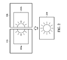
- FIG. 2 is a diagram illustrating displaying an image data together according to an embodiment of the invention.
- the storage device 118 is configured to store image data 210.
- Each of mobile devices 110, 120 may comprise an application program.
- the mobile devices 110, 120 may share the image data 210 wirelessly via the application programs concurrently.
- the image data 210 may be a movie, a TV program, or a picture. As shown in FIG. 2 , the image data can be divided up into sub-images 210a, 210b.
- each of the monitors 116, 126 may display part of the image data 210, e.g., the monitors 116, 126 display sub-images 210a, 210b, respectively, to constitute a complete image data 210.
- the compound electronic device 100 may comprise 4, 9, or more mobile devices that display one image data together via attraction of the electromagnets.
- FIG. 3 is a diagram illustrating a compound electronic device according to an embodiment of the invention.
- a server 310 of an online game is coupled to the mobile devices 110, 120 in a wired or wireless way, and transmits commands B1, B2 to the mobile devices 110, 120, respectively.
- the monitor 116 of the mobile device 110 and the monitor 126 of the mobile device 120 may display frames 320a, 320b of the online game according to the commands B1, B2, respectively.
- the frame 320a is a background
- the frame 320b is a map thumbnail of the online game.
- the frames 320a, 320b may be combined to constitute another background of the online game.
- FIG. 4 is a diagram illustrating a compound electronic device according to an embodiment of the invention.
- a server 410 is coupled to the mobile device 120 in a wired or wireless way, and transmits a control command C1.
- the electromagnet 122 of the mobile device 120 may comprise a plurality of the sub-electromagnets 122a, 122b, 122c, 122d that are disposed on four sides of the mobile device 120, respectively. Although there are only 4 sub-electromagnets disposed on the 4 sides as shown in FIG. 4 , there may be different number of the sub-electromagnets, e.g., 2 sub-electromagnets disposed on 2 sides of the mobile device 120, respectively.
- the mobile device 120 may receive the control command C1 and select one of the plurality of sub-electromagnets according to the control command C 1 in order to attract the electromagnet 112 of the mobile device 110.
- the processor (not shown) of the mobile device 120 will command the sub-electromagnet 122a to generate a second magnetic pole with a polarity that is opposite to a polarity of a first magnetic pole of the electromagnet 112.
- the other sub-electromagnets 122b, 122c, 122d can have no power and can be non-magnetic. Therefore, the mobile device 120 can be coupled to the electromagnet 112 of the mobile device 110 through the sub-electromagnet 122a selected by the server 410.
- FIG. 5 is a diagram illustrating a compound electronic device according to an embodiment of the invention.
- the electromagnet 122 of the mobile device 120 may comprise a plurality of the sub-electromagnets 122a, 122b, 122c, 122d that are disposed on four sides of the mobile device 120, respectively. Although there are only 4 sub-electromagnets disposed on the 4 sides as shown in FIG. 5 , there may be different number of the sub-electromagnets, e.g., 2 sub-electromagnets disposed on 2 sides of the mobile device 120, respectively.
- the sensor 124 of the mobile device 120 may comprise a plurality of sub-sensors 124a, 124b, 124c, 124d that are disposed on four sides of the mobile device 120, respectively. Although there are only 4 sub-sensors disposed on the 4 sides as shown in FIG. 5 , there may be different number of sub-sensors, e.g., 2 sub-sensors disposed on 2 sides of the mobile device 120, respectively.
- the sub-sensors 124a, 124b, 124c, 124d detect distances d1, d2, d3, d4 between the electromagnet 112 and the sub-electromagnets 122a, 122b, 122c, 122d, respectively.
- the processor (not shown) of the mobile device 120 may determine which one is the shortest among distances d1, d2, d3, d4 and select one of the sub-electromagnets 122a, 122b, 122c, 122d that has the shortest distance of all detected distances d1, d2, d3, d4. For example, if the processor determines that the distance d1 is the shortest, it will command the sub-electromagnet 122a to generate a second magnetic pole with a polarity that is opposite to a polarity of a first magnetic pole of the electromagnet 112.
- the other sub-electromagnets 122b, 122c, 122d can have no power and can be non-magnetic. Therefore, the mobile device 120 can be coupled to the electromagnet 112 of the mobile device 110 through the nearest sub-electromagnet 122a.
- FIG. 6 is a diagram illustrating a compound electronic device according to an embodiment of the invention.
- the electromagnet 122 of the mobile device 120 may comprise a plurality of the sub-electromagnets 122a, 122b that are disposed on two sides of the mobile device 120, respectively. Although there are only 2 sub-electromagnets disposed on the 2 sides as shown in FIG. 6 , there may be different number of the sub-electromagnets, e.g., 4 sub-electromagnets disposed on 4 sides of the mobile device 120, respectively.
- the storage device 118 of the mobile device 110 is configured to store image data 210. Each of the mobile devices comprises an application program.
- the mobile devices 110, 120 may share the image data 210.
- the image data 210 may be a movie, a TV program, or a picture.
- the image data 210 may be divided up into sub-images 210a, 210b.
- the mobile device 110 is coupled to the mobile device 120, and both display the image data 210 together.
- the mobile devices 110, 120 are separated from each other, and each of the monitors 116, 126 displays a part of the image data 210, e.g., the monitor 116 displays the sub-image 210a, and the monitor 126 displays the sub-image 210b.
- a processor (not shown) of the mobile device 120 will select one of the sub-electromagnets 122a, 122b to be coupled to the electromagnet 112 of the mobile device 110 in order to combine the sub-images 210a, 210b into the complete data image 210.
- the processor of the mobile device 120 must command the sub-electromagnet 122a to generate a second magnetic pole with a polarity that is opposite to a polarity of a first magnetic pole of the electromagnet 112.
- the other sub-electromagnet 122b can have no power and can be non-magnetic. Therefore, a wrong combination of mobile devices and a wrong display can be avoided.
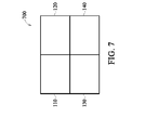
- FIG. 7 is a diagram illustrating a compound electronic device according to an embodiment of the invention.
- the mobile devices 110, 120, 130, 140 are combined into a compound electronic device 700 via attraction of the sub-electromagnets disposed on four sides of each of the mobile devices 110, 120, 130, 140.
- there are only 4 mobile devices combined as shown in FIG.7 there may be 6, 8, 9, or more mobile devices combined into one compound electronic device shaped like a rectangular.
- FIG. 8A is a diagram illustrating a compound electronic device according to an embodiment of the invention.
- the mobile devices 110, 120, 130 are combined into a compound electronic device 800a via attraction of the sub-electromagnets disposed on four sides of each of the mobile devices 110, 120, 130.
- there are only 3 mobile devices combined as shown in FIG. 8 there may be 3, 5, 7, or more mobile devices combined into one compound electronic device shaped like a non-rectangle.
- FIG. 8B is a diagram illustrating a compound electronic device according to an embodiment of the invention. As shown in FIG. 8B , the mobile devices 150, 160 having different sizes can be combined into a compound electronic device 800b via attraction of the sub-electromagnets disposed on four sides of each of the mobile devices 150, 160.
- FIG. 9 is a flow chart 900 illustrating an image displaying method according to an embodiment of the invention.
- a first magnetic pole via a first mobile device is generated.
- the first magnetic pole is detected and an enable signal is generated according to the first magnetic pole via a second mobile device.
- a second magnetic pole opposite to the first magnetic pole is generated according to the enable signal via the second mobile device.
- the first and second mobile devices are combined via attraction of the first and second magnetic poles in order to display image data together, to end the flow chart.
- the way to display the image data is shown in FIG. 2 , 3 , and 6 .
- polarity of an electromagnet can be adjusted in order to combine a plurality of mobile devices easily.
- the sensor can reduce power consumption of the plurality of electromagnets.
Landscapes
- Engineering & Computer Science (AREA)
- Theoretical Computer Science (AREA)
- Human Computer Interaction (AREA)
- Computer Hardware Design (AREA)
- Physics & Mathematics (AREA)
- General Engineering & Computer Science (AREA)
- General Physics & Mathematics (AREA)
- Computer Networks & Wireless Communication (AREA)
- Signal Processing (AREA)
- Multimedia (AREA)
- Controls And Circuits For Display Device (AREA)
Abstract
Description
- This Application claims priority of Taiwan Patent Application No.
100108678 filed on March 15, 2011 - The disclosure generally relates to a compound electronic device, and more particularly, relates to a compound electronic device which combines a plurality of mobile devices together.
- Personal mobile electronic devices, e.g., mobile phones, tablet PCs, PDA (personal digital assistant), and notebooks, have become a necessity in modern daily life. Personal mobile electronic devices are expected to be compact in size for convenience. However, some personal mobile electronic devices with monitors can not provide large and clear images due to the small size limitations. For instance, a mobile phone can be utilized for playing movies, but a user would prefer viewing movies on a TV or PC, due to the small screen of the mobile phone.
- To solve above problem, a compound electronic device which quickly combines a plurality of mobile devices together is desired.
- In one exemplary embodiment, the disclosure is directed to a compound electronic device, comprising: a first mobile device, comprising: a first electromagnet, generating a first magnetic pole; and a first monitor; a second mobile device, comprising: a sensor, detecting the first magnetic pole, and generating an enable signal according to the first magnetic pole; a second electromagnetic, generating a second magnetic pole opposite to the first magnetic pole according to the enable signal; and a second monitor, wherein the first mobile device is coupled to the second mobile device via attraction of the first and second magnetic poles.
- In another exemplary embodiment, the disclosure is directed to an image displaying method, comprising the steps of: generating a first magnetic pole via a first mobile device; detecting the first magnetic pole and generating an enable signal according to the first magnetic pole via a second mobile device; and generating a second magnetic pole opposite to the first magnetic pole according to the enable signal via the second mobile device, wherein the first mobile device is coupled to the second mobile device via attraction of the first and second magnetic poles in order to display image data together.
- The invention can be more fully understood by reading the subsequent detailed description and examples with references made to the accompanying drawings, wherein:
-
FIG. 1 is a diagram illustrating a compound electronic device according to an embodiment of the invention; -
FIG. 2 is a diagram illustrating displaying an image data together according to an embodiment of the invention; -
FIG. 3 is a diagram illustrating a compound electronic device according to an embodiment of the invention; -
FIG. 4 is a diagram illustrating a compound electronic device according to an embodiment of the invention; -
FIG. 5 is a diagram illustrating a compound electronic device according to an embodiment of the invention; -
FIG. 6 is a diagram illustrating a compound electronic device according to an embodiment of the invention; -
FIG. 7 is a diagram illustrating a compound electronic device according to an embodiment of the invention; -
FIG. 8A is a diagram illustrating a compound electronic device according to an embodiment of the invention; -
FIG. 8B is a diagram illustrating a compound electronic device according to an embodiment of the invention; -
FIG. 9 is a flow chart illustrating an image displaying method according to an embodiment of the invention. -
FIG. 1 is a diagram illustrating a compoundelectronic device 100 according to an embodiment of the invention. As shown inFIG. 1 , the compoundelectronic device 100 comprisesmobile devices mobile device 110 may comprise: anelectromagnet 112, amonitor 116, and astorage device 118. Themobile device 120 may comprise: anelectromagnet 122, asensor 124, amonitor 126, and aprocessor 128. Theprocessor 128 is coupled to thesensor 124 and theelectromagnet 122. Theelectromagnets sensor 124 may be a hall sensor to detect nearby magnetic poles or magnetic fields. Themonitors storage device 118 may be a memory, a hard disc, or DVD - To begin, the
electromagnet 112 of themobile device 110 generates a first magnetic pole, N pole or S pole. It is noted that an electromagnetic must generate two magnetic poles at two ends concurrently, and the first magnetic pole means a magnetic pole of theelectromagnet 112 that generates a magnetic field toward the outside of themobile device 110. When a distance between themobile devices sensor 124 can detect near by magnetic fields, determine whether the first magnetic pole is an N pole or S pole, and generate an enable signal A1 according to the detection. Theprocessor 128 of themobile device 120 can determine a current direction of theelectromagnet 122 to generate a second magnetic pole opposite to the first magnetic pole according to the enable signal A1. For example, if the first magnetic pole is an N pole, the second magnetic pole is an S pole; and if the first magnetic pole is an S pole, the second magnetic pole is an N pole. Finally, theelectromagnets mobile device 110 is coupled to themobile device 120 via attraction of theelectromagnets mobile device 110 is coupled to themobile device 120, each of themobile devices sensor 124 of themobile device 120 detects nearby magnetic fields as shown inFIG. 1 , themobile device 110 can also comprise another sensor and processor and be coupled to themobile device 120 in the same way. Themobile devices -
FIG. 2 is a diagram illustrating displaying an image data together according to an embodiment of the invention. Thestorage device 118 is configured to storeimage data 210. Each ofmobile devices mobile devices image data 210 wirelessly via the application programs concurrently. Theimage data 210 may be a movie, a TV program, or a picture. As shown inFIG. 2 , the image data can be divided up intosub-images mobile device 110 is coupled to themobile device 120, each of themonitors image data 210, e.g., themonitors display sub-images complete image data 210. Although there are only two mobile devices as shown inFIG. 2 , the compoundelectronic device 100 may comprise 4, 9, or more mobile devices that display one image data together via attraction of the electromagnets. -
FIG. 3 is a diagram illustrating a compound electronic device according to an embodiment of the invention. As shown inFIG. 3 , aserver 310 of an online game is coupled to themobile devices mobile devices monitor 116 of themobile device 110 and themonitor 126 of themobile device 120 may displayframes frame 320a is a background, and theframe 320b is a map thumbnail of the online game. In another embodiment, theframes mobile devices -
FIG. 4 is a diagram illustrating a compound electronic device according to an embodiment of the invention. As shown inFIG. 4 , aserver 410 is coupled to themobile device 120 in a wired or wireless way, and transmits a control command C1. Theelectromagnet 122 of themobile device 120 may comprise a plurality of thesub-electromagnets mobile device 120, respectively. Although there are only 4 sub-electromagnets disposed on the 4 sides as shown inFIG. 4 , there may be different number of the sub-electromagnets, e.g., 2 sub-electromagnets disposed on 2 sides of themobile device 120, respectively. During the connection, themobile device 120 may receive the control command C1 and select one of the plurality of sub-electromagnets according to the control command C 1 in order to attract theelectromagnet 112 of themobile device 110. For example, if the control command C1 indicates the sub-electromagnet 122a, the processor (not shown) of themobile device 120 will command the sub-electromagnet 122a to generate a second magnetic pole with a polarity that is opposite to a polarity of a first magnetic pole of theelectromagnet 112. The other sub-electromagnets 122b, 122c, 122d can have no power and can be non-magnetic. Therefore, themobile device 120 can be coupled to theelectromagnet 112 of themobile device 110 through the sub-electromagnet 122a selected by theserver 410. -
FIG. 5 is a diagram illustrating a compound electronic device according to an embodiment of the invention. As shown inFIG. 5 , theelectromagnet 122 of themobile device 120 may comprise a plurality of the sub-electromagnets 122a, 122b, 122c, 122d that are disposed on four sides of themobile device 120, respectively. Although there are only 4 sub-electromagnets disposed on the 4 sides as shown inFIG. 5 , there may be different number of the sub-electromagnets, e.g., 2 sub-electromagnets disposed on 2 sides of themobile device 120, respectively. Thesensor 124 of themobile device 120 may comprise a plurality of sub-sensors 124a, 124b, 124c, 124d that are disposed on four sides of themobile device 120, respectively. Although there are only 4 sub-sensors disposed on the 4 sides as shown inFIG. 5 , there may be different number of sub-sensors, e.g., 2 sub-sensors disposed on 2 sides of themobile device 120, respectively. The sub-sensors 124a, 124b, 124c, 124d detect distances d1, d2, d3, d4 between theelectromagnet 112 and the sub-electromagnets 122a, 122b, 122c, 122d, respectively. The processor (not shown) of themobile device 120 may determine which one is the shortest among distances d1, d2, d3, d4 and select one of the sub-electromagnets 122a, 122b, 122c, 122d that has the shortest distance of all detected distances d1, d2, d3, d4. For example, if the processor determines that the distance d1 is the shortest, it will command the sub-electromagnet 122a to generate a second magnetic pole with a polarity that is opposite to a polarity of a first magnetic pole of theelectromagnet 112. The other sub-electromagnets 122b, 122c, 122d can have no power and can be non-magnetic. Therefore, themobile device 120 can be coupled to theelectromagnet 112 of themobile device 110 through thenearest sub-electromagnet 122a. -
FIG. 6 is a diagram illustrating a compound electronic device according to an embodiment of the invention. As shown inFIG. 6 , theelectromagnet 122 of themobile device 120 may comprise a plurality of the sub-electromagnets 122a, 122b that are disposed on two sides of themobile device 120, respectively. Although there are only 2 sub-electromagnets disposed on the 2 sides as shown inFIG. 6 , there may be different number of the sub-electromagnets, e.g., 4 sub-electromagnets disposed on 4 sides of themobile device 120, respectively. Thestorage device 118 of themobile device 110 is configured to storeimage data 210. Each of the mobile devices comprises an application program. Through wireless connection and the application program, themobile devices image data 210. Theimage data 210 may be a movie, a TV program, or a picture. Theimage data 210 may be divided up into sub-images 210a, 210b. To begin, themobile device 110 is coupled to themobile device 120, and both display theimage data 210 together. Next, themobile devices monitors image data 210, e.g., themonitor 116 displays the sub-image 210a, and themonitor 126 displays the sub-image 210b. If a user wants to combine themobile devices mobile device 120 will select one of the sub-electromagnets 122a, 122b to be coupled to theelectromagnet 112 of themobile device 110 in order to combine the sub-images 210a, 210b into thecomplete data image 210. For example, the processor of themobile device 120 must command the sub-electromagnet 122a to generate a second magnetic pole with a polarity that is opposite to a polarity of a first magnetic pole of theelectromagnet 112. The other sub-electromagnet 122b can have no power and can be non-magnetic. Therefore, a wrong combination of mobile devices and a wrong display can be avoided. -
FIG. 7 is a diagram illustrating a compound electronic device according to an embodiment of the invention. As shown inFIG. 7 , themobile devices electronic device 700 via attraction of the sub-electromagnets disposed on four sides of each of themobile devices FIG.7 , there may be 6, 8, 9, or more mobile devices combined into one compound electronic device shaped like a rectangular. -
FIG. 8A is a diagram illustrating a compound electronic device according to an embodiment of the invention. As shown inFIG. 8A , themobile devices electronic device 800a via attraction of the sub-electromagnets disposed on four sides of each of themobile devices FIG. 8 , there may be 3, 5, 7, or more mobile devices combined into one compound electronic device shaped like a non-rectangle. -
FIG. 8B is a diagram illustrating a compound electronic device according to an embodiment of the invention. As shown inFIG. 8B , themobile devices electronic device 800b via attraction of the sub-electromagnets disposed on four sides of each of themobile devices -
FIG. 9 is aflow chart 900 illustrating an image displaying method according to an embodiment of the invention. To begin, in step S902, a first magnetic pole via a first mobile device is generated. In step S904, the first magnetic pole is detected and an enable signal is generated according to the first magnetic pole via a second mobile device. In step S906, a second magnetic pole opposite to the first magnetic pole is generated according to the enable signal via the second mobile device. Finally, in step S908, the first and second mobile devices are combined via attraction of the first and second magnetic poles in order to display image data together, to end the flow chart.. The way to display the image data is shown inFIG. 2 ,3 , and6 . - In prior art, permanent magnets are usually utilized which combines a plurality of apparatuses. According to the invention, polarity of an electromagnet can be adjusted in order to combine a plurality of mobile devices easily. Moreover, the sensor can reduce power consumption of the plurality of electromagnets.
- It will be apparent to those skilled in the art that various modifications and variations can be made in the invention. It is intended that the standard and examples be considered as exemplary only, with a true scope of the disclosed embodiments being indicated by the following claims and their equivalents.
Claims (15)
- A compound electronic device, comprising:a first mobile device, comprising:a first electromagnet, arranged for generating a first magnetic pole; anda first monitor; anda second mobile device, comprising:a sensor, arranged for detecting the first magnetic pole, and generating an enable signal according to the first magnetic pole;a second electromagnetic, arranged for generating a second magnetic pole opposite to the first magnetic pole according to the enable signal; anda second monitor,wherein the first mobile device is coupled to the second mobile device via attraction of the first and second magnetic poles.
- The compound electronic device as claimed in claim 1, wherein when the first mobile device is coupled to the second mobile device, each of the first and second mobile devices generates a vibration alert.
- The compound electronic device as claimed in claim 1, wherein when the first mobile device is coupled to the second mobile device, the first monitor is arranged for displaying a first sub-image of an image data, the second monitor is arranged for displaying a second sub-image of the image data, and the first and second sub-images constitute the complete image data.
- The compound electronic device as claimed in claim 3, wherein each of the first and second mobile devices comprises an application program, and shares the image data via the application program.
- The compound electronic device as claimed in claim 1, wherein:the first mobile device receives a first command from a server, and the second mobile device receives a second command from the server;the first monitor is arranged for displaying a first frame of an online game according to the first command; andthe second monitor is arranged for displaying a second frame of the online game according to the second command.
- The compound electronic device as claimed in claim 1, wherein:the second electromagnet comprises a plurality of sub-electromagnets, and each of which is disposed on each of sides of the second mobile device; andthe second mobile device is arranged for determining a polarity of one of the plurality of sub-electromagnets according to a control command from a server in order to attract the first electromagnet.
- The compound electronic device as claimed in claim 1, wherein:the second electromagnet comprises a plurality of sub-electromagnets, and each of which is disposed on each of sides of the second mobile device;the sensor comprises a plurality of sub-sensors, each of which is disposed on each of the sides of the second mobile device and configured to detect a distance between each of the plurality of sub-electromagnets and the first electromagnet; andthe second mobile device is arranged for determining the polarity of one of the plurality of sub-electromagnets that has the shortest detected distance in order to attract the first electromagnet.
- The compound electronic device as claimed in claim 1, wherein:the second electromagnet comprises a plurality of sub-electromagnets, and each of which is disposed on each of sides of the second mobile device;the first monitor is arranged for displaying a first sub-image of an image data;the second monitor is arranged for displaying a second sub-image of the image data; andthe second mobile device is arranged for determining a polarity of one of the plurality of sub-electromagnets according to the first and second sub-images in order to attract the first electromagnet and combine the first and second sub-images into the complete image data.
- An image displaying method, comprising the steps of:generating a first magnetic pole via a first mobile device;detecting the first magnetic pole and generating an enable signal according to the first magnetic pole via a second mobile device;generating a second magnetic pole opposite to the first magnetic pole according to the enable signal via the second mobile device; and combining the first and second mobile devices via attraction of the first and second magnetic poles in order to display image data together.
- The image displaying method as claimed in claim 9, wherein when the first and second mobile devices are combined together, each of the first and second mobile devices generates a vibration alert.
- The image displaying method as claimed in claim 9, wherein when the first and second mobile devices are combined together, the method further comprises:displaying a first sub-image of an image data via the first mobile device; anddisplaying a second sub-image of the image data via the second mobile device,wherein the first and second sub-images constitute the complete image data.
- The image displaying method as claimed in claim 9, further comprising the steps of:receiving a first command and a second command via the first and second mobile devices, respectively, from a server;displaying a first frame of an online game according to the first command via the first mobile device; anddisplaying a second frame of the online game according to the second command via the second mobile device.
- The compound electronic device as claimed in claim 5 or the image displaying method as claimed in claim 12, wherein the first frame is a background of the online game, and the second frame is a map thumbnail of the online game.
- The image displaying method as claimed in claim 9, wherein the second mobile device comprises a plurality of the sub-electromagnets, each of which is disposed on each side of the second mobile device, and the image displaying method further comprises the steps of:detecting, via the second mobile device, a distance between each of the plurality of the sub-electromagnets and the first electromagnet; and determining, via the second mobile device, the polarity of one of the plurality of the sub-electromagnets that has the shortest detected distance in order for connection to the first mobile device.
- The image displaying method as claimed in claim 9, wherein the second mobile device comprises a plurality of the sub-electromagnets, each of which is disposed on each side of the second mobile device, and the image displaying method further comprises the steps of:displaying a first sub-image of the image data via the first mobile device; anddisplaying a second sub-image of the image data via the second mobile device,wherein the second mobile device determines the polarity of one of the plurality of the sub-electromagnets according to the first and second sub-images in order for connection to the first mobile device and combines the first and second sub-images into the complete image data.
Applications Claiming Priority (1)
| Application Number | Priority Date | Filing Date | Title |
|---|---|---|---|
| TW100108678A TW201237740A (en) | 2011-03-15 | 2011-03-15 | Compound electrical devices and methods for displaying image data |
Publications (2)
| Publication Number | Publication Date |
|---|---|
| EP2501115A1 true EP2501115A1 (en) | 2012-09-19 |
| EP2501115B1 EP2501115B1 (en) | 2013-12-25 |
Family
ID=45002671
Family Applications (1)
| Application Number | Title | Priority Date | Filing Date |
|---|---|---|---|
| EP11188510.9A Not-in-force EP2501115B1 (en) | 2011-03-15 | 2011-11-09 | Compound electronic device and method for displaying image data |
Country Status (3)
| Country | Link |
|---|---|
| US (1) | US20120235776A1 (en) |
| EP (1) | EP2501115B1 (en) |
| TW (1) | TW201237740A (en) |
Cited By (3)
| Publication number | Priority date | Publication date | Assignee | Title |
|---|---|---|---|---|
| GB2506923A (en) * | 2012-10-15 | 2014-04-16 | Renergy Sarl | Releasably joining a mobile communication device to another portable electronic device to provide a larger, substantially seamless display screen |
| EP2816464A1 (en) * | 2013-06-17 | 2014-12-24 | Samsung Electronics Co., Ltd | Display system and control method thereof |
| WO2019240384A1 (en) | 2018-06-14 | 2019-12-19 | Samsung Electronics Co., Ltd. | Modular display apparatus and method for controlling thereof |
Families Citing this family (2)
| Publication number | Priority date | Publication date | Assignee | Title |
|---|---|---|---|---|
| TWI456234B (en) * | 2012-09-17 | 2014-10-11 | Nat Chengchi University | Method and device for determining relative position between mobile devices |
| KR102363605B1 (en) * | 2015-10-20 | 2022-02-17 | 오리온디스플레이 주식회사 | Method for setting a identification mark of a individual display device in a multi display system |
Citations (4)
| Publication number | Priority date | Publication date | Assignee | Title |
|---|---|---|---|---|
| US20060088277A1 (en) * | 2004-10-26 | 2006-04-27 | Pantech & Curitel Communications, Inc. | Image/audio playback device of mobile communication terminal |
| US20070213093A1 (en) * | 2006-03-06 | 2007-09-13 | Samsung Electronics Co., Ltd. | Mobile terminal having wide viewing function digital broadcasting |
| US20090034209A1 (en) * | 2007-08-03 | 2009-02-05 | Samsung Electronics Co., Ltd. | Multi-module combination type portable electronic device |
| US20090189829A1 (en) * | 2008-01-30 | 2009-07-30 | Kabushiki Kaisha Toshiba | Information processing apparatus |
Family Cites Families (4)
| Publication number | Priority date | Publication date | Assignee | Title |
|---|---|---|---|---|
| TWI285305B (en) * | 2005-11-07 | 2007-08-11 | High Tech Comp Corp | Auto-aligning and connecting structure between electronic device and accessory |
| WO2007062268A2 (en) * | 2005-11-28 | 2007-05-31 | University Of Florida Research Foundation, Inc. | Method and structure for magnetically-directed, self-assembly of three-dimensional structures |
| KR101181385B1 (en) * | 2007-01-18 | 2012-09-20 | 삼성테크윈 주식회사 | Magnetic levitation sliding structure |
| US8264310B2 (en) * | 2010-09-17 | 2012-09-11 | Apple Inc. | Accessory device for peek mode |
-
2011
- 2011-03-15 TW TW100108678A patent/TW201237740A/en unknown
- 2011-09-23 US US13/242,636 patent/US20120235776A1/en not_active Abandoned
- 2011-11-09 EP EP11188510.9A patent/EP2501115B1/en not_active Not-in-force
Patent Citations (4)
| Publication number | Priority date | Publication date | Assignee | Title |
|---|---|---|---|---|
| US20060088277A1 (en) * | 2004-10-26 | 2006-04-27 | Pantech & Curitel Communications, Inc. | Image/audio playback device of mobile communication terminal |
| US20070213093A1 (en) * | 2006-03-06 | 2007-09-13 | Samsung Electronics Co., Ltd. | Mobile terminal having wide viewing function digital broadcasting |
| US20090034209A1 (en) * | 2007-08-03 | 2009-02-05 | Samsung Electronics Co., Ltd. | Multi-module combination type portable electronic device |
| US20090189829A1 (en) * | 2008-01-30 | 2009-07-30 | Kabushiki Kaisha Toshiba | Information processing apparatus |
Cited By (5)
| Publication number | Priority date | Publication date | Assignee | Title |
|---|---|---|---|---|
| GB2506923A (en) * | 2012-10-15 | 2014-04-16 | Renergy Sarl | Releasably joining a mobile communication device to another portable electronic device to provide a larger, substantially seamless display screen |
| EP2816464A1 (en) * | 2013-06-17 | 2014-12-24 | Samsung Electronics Co., Ltd | Display system and control method thereof |
| US9535648B2 (en) | 2013-06-17 | 2017-01-03 | Samsung Electronics Co., Ltd. | Display system and control method thereof |
| WO2019240384A1 (en) | 2018-06-14 | 2019-12-19 | Samsung Electronics Co., Ltd. | Modular display apparatus and method for controlling thereof |
| EP3752907A4 (en) * | 2018-06-14 | 2021-06-23 | Samsung Electronics Co., Ltd. | MODULAR DISPLAY DEVICE AND ASSOCIATED CONTROL PROCESS |
Also Published As
| Publication number | Publication date |
|---|---|
| TW201237740A (en) | 2012-09-16 |
| US20120235776A1 (en) | 2012-09-20 |
| EP2501115B1 (en) | 2013-12-25 |
Similar Documents
| Publication | Publication Date | Title |
|---|---|---|
| US8810512B2 (en) | Methods of launching applications responsive to device orientation and related electronic devices | |
| KR102049075B1 (en) | Method and apparatus for displaying information on wireless charging pad in electronic device | |
| US10942558B2 (en) | User interface adaptation based on detected user location | |
| US20220057984A1 (en) | Music playing method, device, terminal and storage medium | |
| US8199960B2 (en) | Integrated speaker and display | |
| AU2016324578B2 (en) | Camera module including multi-lens and electronic device having the same | |
| US8340695B2 (en) | Mobile terminal and method of controlling the operation of the mobile terminal | |
| US9134949B2 (en) | Head mount display and method for controlling output of the same | |
| EP2501115B1 (en) | Compound electronic device and method for displaying image data | |
| EP3376366A1 (en) | Content display using multiple display devices | |
| US11303591B2 (en) | Management system for audio and visual content | |
| US20120040720A1 (en) | Mobile terminal, display device and controlling method thereof | |
| US20120038541A1 (en) | Mobile terminal, display device and controlling method thereof | |
| US20160170709A1 (en) | Device and method for controlling sound output | |
| US10061551B2 (en) | Device configuration including a master communications device with a slave device extension | |
| KR20140113361A (en) | Apparatus and method controlling display | |
| JP2015060457A (en) | Distribution device, distribution method, and distribution program | |
| WO2012120346A1 (en) | Electronic apparatus use environment detecting method, electronic apparatus performance optimizing method and electronic apparatus | |
| EP3851947A1 (en) | Method and apparatus for control of orientation of information presented based upon device use state | |
| WO2014034256A1 (en) | Display control apparatus, display control system, and display control method | |
| US20200296457A1 (en) | Attention based media control | |
| CN106503124A (en) | The method and apparatus of multimedia file positioning in the page | |
| CN112911337A (en) | Method and device for configuring video cover pictures of terminal equipment | |
| JP2012010212A (en) | Image display device and program | |
| US9319775B2 (en) | Electronic apparatus, and method of providing of sound |
Legal Events
| Date | Code | Title | Description |
|---|---|---|---|
| PUAI | Public reference made under article 153(3) epc to a published international application that has entered the european phase |
Free format text: ORIGINAL CODE: 0009012 |
|
| AK | Designated contracting states |
Kind code of ref document: A1 Designated state(s): AL AT BE BG CH CY CZ DE DK EE ES FI FR GB GR HR HU IE IS IT LI LT LU LV MC MK MT NL NO PL PT RO RS SE SI SK SM TR |
|
| AX | Request for extension of the european patent |
Extension state: BA ME |
|
| 17P | Request for examination filed |
Effective date: 20120905 |
|
| GRAP | Despatch of communication of intention to grant a patent |
Free format text: ORIGINAL CODE: EPIDOSNIGR1 |
|
| INTG | Intention to grant announced |
Effective date: 20130625 |
|
| GRAS | Grant fee paid |
Free format text: ORIGINAL CODE: EPIDOSNIGR3 |
|
| GRAA | (expected) grant |
Free format text: ORIGINAL CODE: 0009210 |
|
| AK | Designated contracting states |
Kind code of ref document: B1 Designated state(s): AL AT BE BG CH CY CZ DE DK EE ES FI FR GB GR HR HU IE IS IT LI LT LU LV MC MK MT NL NO PL PT RO RS SE SI SK SM TR |
|
| REG | Reference to a national code |
Ref country code: GB Ref legal event code: FG4D |
|
| REG | Reference to a national code |
Ref country code: CH Ref legal event code: EP |
|
| REG | Reference to a national code |
Ref country code: AT Ref legal event code: REF Ref document number: 647109 Country of ref document: AT Kind code of ref document: T Effective date: 20140115 |
|
| REG | Reference to a national code |
Ref country code: IE Ref legal event code: FG4D |
|
| REG | Reference to a national code |
Ref country code: DE Ref legal event code: R096 Ref document number: 602011004341 Country of ref document: DE Effective date: 20140220 |
|
| PG25 | Lapsed in a contracting state [announced via postgrant information from national office to epo] |
Ref country code: SE Free format text: LAPSE BECAUSE OF FAILURE TO SUBMIT A TRANSLATION OF THE DESCRIPTION OR TO PAY THE FEE WITHIN THE PRESCRIBED TIME-LIMIT Effective date: 20131225 Ref country code: FI Free format text: LAPSE BECAUSE OF FAILURE TO SUBMIT A TRANSLATION OF THE DESCRIPTION OR TO PAY THE FEE WITHIN THE PRESCRIBED TIME-LIMIT Effective date: 20131225 Ref country code: HR Free format text: LAPSE BECAUSE OF FAILURE TO SUBMIT A TRANSLATION OF THE DESCRIPTION OR TO PAY THE FEE WITHIN THE PRESCRIBED TIME-LIMIT Effective date: 20131225 Ref country code: NO Free format text: LAPSE BECAUSE OF FAILURE TO SUBMIT A TRANSLATION OF THE DESCRIPTION OR TO PAY THE FEE WITHIN THE PRESCRIBED TIME-LIMIT Effective date: 20140325 Ref country code: LT Free format text: LAPSE BECAUSE OF FAILURE TO SUBMIT A TRANSLATION OF THE DESCRIPTION OR TO PAY THE FEE WITHIN THE PRESCRIBED TIME-LIMIT Effective date: 20131225 |
|
| REG | Reference to a national code |
Ref country code: NL Ref legal event code: VDEP Effective date: 20131225 |
|
| REG | Reference to a national code |
Ref country code: AT Ref legal event code: MK05 Ref document number: 647109 Country of ref document: AT Kind code of ref document: T Effective date: 20131225 |
|
| REG | Reference to a national code |
Ref country code: LT Ref legal event code: MG4D |
|
| PG25 | Lapsed in a contracting state [announced via postgrant information from national office to epo] |
Ref country code: RS Free format text: LAPSE BECAUSE OF FAILURE TO SUBMIT A TRANSLATION OF THE DESCRIPTION OR TO PAY THE FEE WITHIN THE PRESCRIBED TIME-LIMIT Effective date: 20131225 Ref country code: LV Free format text: LAPSE BECAUSE OF FAILURE TO SUBMIT A TRANSLATION OF THE DESCRIPTION OR TO PAY THE FEE WITHIN THE PRESCRIBED TIME-LIMIT Effective date: 20131225 |
|
| PG25 | Lapsed in a contracting state [announced via postgrant information from national office to epo] |
Ref country code: EE Free format text: LAPSE BECAUSE OF FAILURE TO SUBMIT A TRANSLATION OF THE DESCRIPTION OR TO PAY THE FEE WITHIN THE PRESCRIBED TIME-LIMIT Effective date: 20131225 Ref country code: IS Free format text: LAPSE BECAUSE OF FAILURE TO SUBMIT A TRANSLATION OF THE DESCRIPTION OR TO PAY THE FEE WITHIN THE PRESCRIBED TIME-LIMIT Effective date: 20140425 Ref country code: BE Free format text: LAPSE BECAUSE OF FAILURE TO SUBMIT A TRANSLATION OF THE DESCRIPTION OR TO PAY THE FEE WITHIN THE PRESCRIBED TIME-LIMIT Effective date: 20131225 |
|
| PG25 | Lapsed in a contracting state [announced via postgrant information from national office to epo] |
Ref country code: CZ Free format text: LAPSE BECAUSE OF FAILURE TO SUBMIT A TRANSLATION OF THE DESCRIPTION OR TO PAY THE FEE WITHIN THE PRESCRIBED TIME-LIMIT Effective date: 20131225 Ref country code: CY Free format text: LAPSE BECAUSE OF FAILURE TO SUBMIT A TRANSLATION OF THE DESCRIPTION OR TO PAY THE FEE WITHIN THE PRESCRIBED TIME-LIMIT Effective date: 20131225 Ref country code: PT Free format text: LAPSE BECAUSE OF FAILURE TO SUBMIT A TRANSLATION OF THE DESCRIPTION OR TO PAY THE FEE WITHIN THE PRESCRIBED TIME-LIMIT Effective date: 20140428 Ref country code: ES Free format text: LAPSE BECAUSE OF FAILURE TO SUBMIT A TRANSLATION OF THE DESCRIPTION OR TO PAY THE FEE WITHIN THE PRESCRIBED TIME-LIMIT Effective date: 20131225 Ref country code: AT Free format text: LAPSE BECAUSE OF FAILURE TO SUBMIT A TRANSLATION OF THE DESCRIPTION OR TO PAY THE FEE WITHIN THE PRESCRIBED TIME-LIMIT Effective date: 20131225 Ref country code: SK Free format text: LAPSE BECAUSE OF FAILURE TO SUBMIT A TRANSLATION OF THE DESCRIPTION OR TO PAY THE FEE WITHIN THE PRESCRIBED TIME-LIMIT Effective date: 20131225 Ref country code: RO Free format text: LAPSE BECAUSE OF FAILURE TO SUBMIT A TRANSLATION OF THE DESCRIPTION OR TO PAY THE FEE WITHIN THE PRESCRIBED TIME-LIMIT Effective date: 20131225 Ref country code: NL Free format text: LAPSE BECAUSE OF FAILURE TO SUBMIT A TRANSLATION OF THE DESCRIPTION OR TO PAY THE FEE WITHIN THE PRESCRIBED TIME-LIMIT Effective date: 20131225 |
|
| REG | Reference to a national code |
Ref country code: DE Ref legal event code: R097 Ref document number: 602011004341 Country of ref document: DE |
|
| PG25 | Lapsed in a contracting state [announced via postgrant information from national office to epo] |
Ref country code: DK Free format text: LAPSE BECAUSE OF FAILURE TO SUBMIT A TRANSLATION OF THE DESCRIPTION OR TO PAY THE FEE WITHIN THE PRESCRIBED TIME-LIMIT Effective date: 20131225 |
|
| PLBE | No opposition filed within time limit |
Free format text: ORIGINAL CODE: 0009261 |
|
| STAA | Information on the status of an ep patent application or granted ep patent |
Free format text: STATUS: NO OPPOSITION FILED WITHIN TIME LIMIT |
|
| PG25 | Lapsed in a contracting state [announced via postgrant information from national office to epo] |
Ref country code: PL Free format text: LAPSE BECAUSE OF FAILURE TO SUBMIT A TRANSLATION OF THE DESCRIPTION OR TO PAY THE FEE WITHIN THE PRESCRIBED TIME-LIMIT Effective date: 20131225 |
|
| 26N | No opposition filed |
Effective date: 20140926 |
|
| REG | Reference to a national code |
Ref country code: DE Ref legal event code: R097 Ref document number: 602011004341 Country of ref document: DE Effective date: 20140926 |
|
| PG25 | Lapsed in a contracting state [announced via postgrant information from national office to epo] |
Ref country code: SI Free format text: LAPSE BECAUSE OF FAILURE TO SUBMIT A TRANSLATION OF THE DESCRIPTION OR TO PAY THE FEE WITHIN THE PRESCRIBED TIME-LIMIT Effective date: 20131225 |
|
| PG25 | Lapsed in a contracting state [announced via postgrant information from national office to epo] |
Ref country code: LU Free format text: LAPSE BECAUSE OF FAILURE TO SUBMIT A TRANSLATION OF THE DESCRIPTION OR TO PAY THE FEE WITHIN THE PRESCRIBED TIME-LIMIT Effective date: 20141109 Ref country code: MC Free format text: LAPSE BECAUSE OF FAILURE TO SUBMIT A TRANSLATION OF THE DESCRIPTION OR TO PAY THE FEE WITHIN THE PRESCRIBED TIME-LIMIT Effective date: 20131225 |
|
| REG | Reference to a national code |
Ref country code: CH Ref legal event code: PL |
|
| PG25 | Lapsed in a contracting state [announced via postgrant information from national office to epo] |
Ref country code: LI Free format text: LAPSE BECAUSE OF NON-PAYMENT OF DUE FEES Effective date: 20141130 Ref country code: CH Free format text: LAPSE BECAUSE OF NON-PAYMENT OF DUE FEES Effective date: 20141130 |
|
| REG | Reference to a national code |
Ref country code: IE Ref legal event code: MM4A |
|
| REG | Reference to a national code |
Ref country code: FR Ref legal event code: PLFP Year of fee payment: 5 |
|
| PG25 | Lapsed in a contracting state [announced via postgrant information from national office to epo] |
Ref country code: IE Free format text: LAPSE BECAUSE OF NON-PAYMENT OF DUE FEES Effective date: 20141109 |
|
| PG25 | Lapsed in a contracting state [announced via postgrant information from national office to epo] |
Ref country code: SM Free format text: LAPSE BECAUSE OF FAILURE TO SUBMIT A TRANSLATION OF THE DESCRIPTION OR TO PAY THE FEE WITHIN THE PRESCRIBED TIME-LIMIT Effective date: 20131225 |
|
| PG25 | Lapsed in a contracting state [announced via postgrant information from national office to epo] |
Ref country code: IT Free format text: LAPSE BECAUSE OF FAILURE TO SUBMIT A TRANSLATION OF THE DESCRIPTION OR TO PAY THE FEE WITHIN THE PRESCRIBED TIME-LIMIT Effective date: 20131225 Ref country code: GR Free format text: LAPSE BECAUSE OF FAILURE TO SUBMIT A TRANSLATION OF THE DESCRIPTION OR TO PAY THE FEE WITHIN THE PRESCRIBED TIME-LIMIT Effective date: 20140326 Ref country code: BG Free format text: LAPSE BECAUSE OF FAILURE TO SUBMIT A TRANSLATION OF THE DESCRIPTION OR TO PAY THE FEE WITHIN THE PRESCRIBED TIME-LIMIT Effective date: 20131225 |
|
| PG25 | Lapsed in a contracting state [announced via postgrant information from national office to epo] |
Ref country code: TR Free format text: LAPSE BECAUSE OF FAILURE TO SUBMIT A TRANSLATION OF THE DESCRIPTION OR TO PAY THE FEE WITHIN THE PRESCRIBED TIME-LIMIT Effective date: 20131225 Ref country code: MT Free format text: LAPSE BECAUSE OF FAILURE TO SUBMIT A TRANSLATION OF THE DESCRIPTION OR TO PAY THE FEE WITHIN THE PRESCRIBED TIME-LIMIT Effective date: 20131225 Ref country code: HU Free format text: LAPSE BECAUSE OF FAILURE TO SUBMIT A TRANSLATION OF THE DESCRIPTION OR TO PAY THE FEE WITHIN THE PRESCRIBED TIME-LIMIT; INVALID AB INITIO Effective date: 20111109 |
|
| REG | Reference to a national code |
Ref country code: FR Ref legal event code: PLFP Year of fee payment: 6 |
|
| REG | Reference to a national code |
Ref country code: FR Ref legal event code: PLFP Year of fee payment: 7 |
|
| PG25 | Lapsed in a contracting state [announced via postgrant information from national office to epo] |
Ref country code: MK Free format text: LAPSE BECAUSE OF FAILURE TO SUBMIT A TRANSLATION OF THE DESCRIPTION OR TO PAY THE FEE WITHIN THE PRESCRIBED TIME-LIMIT Effective date: 20131225 |
|
| REG | Reference to a national code |
Ref country code: FR Ref legal event code: PLFP Year of fee payment: 8 |
|
| PG25 | Lapsed in a contracting state [announced via postgrant information from national office to epo] |
Ref country code: AL Free format text: LAPSE BECAUSE OF FAILURE TO SUBMIT A TRANSLATION OF THE DESCRIPTION OR TO PAY THE FEE WITHIN THE PRESCRIBED TIME-LIMIT Effective date: 20131225 |
|
| PGFP | Annual fee paid to national office [announced via postgrant information from national office to epo] |
Ref country code: GB Payment date: 20231006 Year of fee payment: 13 |
|
| PGFP | Annual fee paid to national office [announced via postgrant information from national office to epo] |
Ref country code: FR Payment date: 20231009 Year of fee payment: 13 Ref country code: DE Payment date: 20231010 Year of fee payment: 13 |
|
| REG | Reference to a national code |
Ref country code: DE Ref legal event code: R119 Ref document number: 602011004341 Country of ref document: DE |
|
| GBPC | Gb: european patent ceased through non-payment of renewal fee |
Effective date: 20241109 |
|
| PG25 | Lapsed in a contracting state [announced via postgrant information from national office to epo] |
Ref country code: DE Free format text: LAPSE BECAUSE OF NON-PAYMENT OF DUE FEES Effective date: 20250603 |
|
| PG25 | Lapsed in a contracting state [announced via postgrant information from national office to epo] |
Ref country code: GB Free format text: LAPSE BECAUSE OF NON-PAYMENT OF DUE FEES Effective date: 20241109 |
|
| PG25 | Lapsed in a contracting state [announced via postgrant information from national office to epo] |
Ref country code: FR Free format text: LAPSE BECAUSE OF NON-PAYMENT OF DUE FEES Effective date: 20241130 |