EP2500899A2 - Image displaying apparatus and image display program - Google Patents
Image displaying apparatus and image display program Download PDFInfo
- Publication number
- EP2500899A2 EP2500899A2 EP12171736A EP12171736A EP2500899A2 EP 2500899 A2 EP2500899 A2 EP 2500899A2 EP 12171736 A EP12171736 A EP 12171736A EP 12171736 A EP12171736 A EP 12171736A EP 2500899 A2 EP2500899 A2 EP 2500899A2
- Authority
- EP
- European Patent Office
- Prior art keywords
- image
- pixels
- monochrome
- display
- lcd
- Prior art date
- Legal status (The legal status is an assumption and is not a legal conclusion. Google has not performed a legal analysis and makes no representation as to the accuracy of the status listed.)
- Granted
Links
Images



Classifications
-
- G—PHYSICS
- G09—EDUCATION; CRYPTOGRAPHY; DISPLAY; ADVERTISING; SEALS
- G09G—ARRANGEMENTS OR CIRCUITS FOR CONTROL OF INDICATING DEVICES USING STATIC MEANS TO PRESENT VARIABLE INFORMATION
- G09G5/00—Control arrangements or circuits for visual indicators common to cathode-ray tube indicators and other visual indicators
- G09G5/20—Function-generator circuits, e.g. circle generators line or curve smoothing circuits
-
- G—PHYSICS
- G06—COMPUTING OR CALCULATING; COUNTING
- G06T—IMAGE DATA PROCESSING OR GENERATION, IN GENERAL
- G06T3/00—Geometric image transformations in the plane of the image
- G06T3/40—Scaling of whole images or parts thereof, e.g. expanding or contracting
- G06T3/4007—Scaling of whole images or parts thereof, e.g. expanding or contracting based on interpolation, e.g. bilinear interpolation
-
- G—PHYSICS
- G09—EDUCATION; CRYPTOGRAPHY; DISPLAY; ADVERTISING; SEALS
- G09G—ARRANGEMENTS OR CIRCUITS FOR CONTROL OF INDICATING DEVICES USING STATIC MEANS TO PRESENT VARIABLE INFORMATION
- G09G2340/00—Aspects of display data processing
- G09G2340/04—Changes in size, position or resolution of an image
- G09G2340/0457—Improvement of perceived resolution by subpixel rendering
-
- G—PHYSICS
- G09—EDUCATION; CRYPTOGRAPHY; DISPLAY; ADVERTISING; SEALS
- G09G—ARRANGEMENTS OR CIRCUITS FOR CONTROL OF INDICATING DEVICES USING STATIC MEANS TO PRESENT VARIABLE INFORMATION
- G09G2380/00—Specific applications
- G09G2380/08—Biomedical applications
-
- G—PHYSICS
- G09—EDUCATION; CRYPTOGRAPHY; DISPLAY; ADVERTISING; SEALS
- G09G—ARRANGEMENTS OR CIRCUITS FOR CONTROL OF INDICATING DEVICES USING STATIC MEANS TO PRESENT VARIABLE INFORMATION
- G09G3/00—Control arrangements or circuits, of interest only in connection with visual indicators other than cathode-ray tubes
- G09G3/20—Control arrangements or circuits, of interest only in connection with visual indicators other than cathode-ray tubes for presentation of an assembly of a number of characters, e.g. a page, by composing the assembly by combination of individual elements arranged in a matrix no fixed position being assigned to or needed to be assigned to the individual characters or partial characters
- G09G3/34—Control arrangements or circuits, of interest only in connection with visual indicators other than cathode-ray tubes for presentation of an assembly of a number of characters, e.g. a page, by composing the assembly by combination of individual elements arranged in a matrix no fixed position being assigned to or needed to be assigned to the individual characters or partial characters by control of light from an independent source
- G09G3/36—Control arrangements or circuits, of interest only in connection with visual indicators other than cathode-ray tubes for presentation of an assembly of a number of characters, e.g. a page, by composing the assembly by combination of individual elements arranged in a matrix no fixed position being assigned to or needed to be assigned to the individual characters or partial characters by control of light from an independent source using liquid crystals
- G09G3/3611—Control of matrices with row and column drivers
Definitions
- the present invention relates to an image displaying apparatus and an image display program and more particularly to an image displaying apparatus and an image display program arranged for driving the sub pixels independently in its LCD (liquid crystal display) to improve the resolution along the major axis of the LCD and displaying a reduced image while maintaining the aspect ratio of an original image.
- LCD liquid crystal display
- An image reducing method for reducing a great number of pixels in an image through simple sampling or operation sampling to produce an image of a small number of pixels (See Patent Citation 1).
- a medical image of 4096x3328 pixels produced by the FPD is reduced to an image of 1477x1200 which can thus be displayed on the LCD of 1600 ⁇ 1200 pixel type.
- the number of pixels along the minor axis in the reduced image is set to 1200 because it corresponds to the number of pixels along the minor axis on the LCD.
- the number of pixels along the major axis in the reduced image is set to 1477 because the aspect ratio of the original image has to be maintained.
- the FPD has a desired degree of the resolution.
- Each pixel on the LCD of the monochrome liquid crystal display consists of three sub pixels aligned along the major axis of the LCD.
- the resolution along the major axis on the LCD can thus be improved by driving independently the three sub pixels such as in the display of Patent Citation 2.
- an image displaying apparatus comprising: an image converting means for reducing and converting an original monochrome image which consists of an array, m rows and n columns, of pixels into a display image which consists of an array, q rows and (3*n*q/m) columns, of pixels where m, n, q, and P are natural numbers and m ⁇ n, q ⁇ P, n/m ⁇ P/q, and m>q are given; and a monochrome liquid crystal display provided with a monochrome LCD, which is composed mainly of an array, q rows and P columns, of pixels for driving the sub pixels independently aligned along the rows of the monochrome LCD to display the display image on the LCD.
- the image displaying apparatus of the first aspect reduces and converts the original monochrome image which consists of an array, m rows and n columns, of pixels into a display image which consists of an array, q rows and (3*n*q/m) columns, of pixels.
- the number of pixels along the row of the original monochrome image is (n*q/m) at the aspect ratio (n/m)
- the number of pixels along the row in the display image is three times greater than that of the original monochrome image at the aspect ratio (n/m) of the original monochrome image.
- the resolution along the row is hence three times higher than that when the sub pixels are driven not independently.
- an image display program for displaying an original monochrome image which consists of an array, m rows and n columns, of pixels on a monochrome LCD, which is composed of an array, q rows and P columns, of pixels, of a monochrome liquid crystal display where m, n, q, and P are natural numbers and m ⁇ n, q ⁇ P, n/m ⁇ P/q, and m>q are given, is provided allowing a computer to act as an original monochrome image inputting means for inputting the original monochrome image from the outside, an image converting means for reducing and converting the original monochrome image into a display image which consists of an array, q rows and (3*n*q/m) columns, of pixels, and a display image outputting means for outputting the display image to the monochrome liquid crystal display in order to display the display image through independently driving the sub pixels of the monochrome LCD.
- the image display program of the second aspect reduces and converts the original monochrome image which consists of an array, m rows and n columns, of pixels into a display image which consists of an array, q rows and (3*n*q/m) columns, of pixels.
- the number of pixels of the original monochrome Image is (n*q/m) at the aspect ratio (n/m)
- the number of pixels along the row in the display image is three times greater than that of the original monochrome image.
- the aspect ratio of the original image can be maintained.
- the resolution along the row is hence three times higher than that when the sub pixels are driven not independently.
- the image displaying apparatus and the image display program according to the present invention allow the image to be reduced from an original image with the aspect ratio remaining unchanged and displayed on the LCD while the resolution along the major axis is improved.
- Fig. 1 is a schematic view of a medical image displaying apparatus 1 illustrating Embodiment 1.
- the medical image displaying apparatus 1 comprises a personal computer 3 for carrying out a medical image viewer program 31 where, when m ⁇ n, q ⁇ P, n/m ⁇ P/q, and m>q where m, n, q, and P are natural numbers, a monochrome medical image data A(i, j) which consists of an array, m rows and n columns, of pixels is entered and converted into a display image data M(k, L) which consists of a reduced array, q rows and
- a monochrome liquid crystal display 4 equipped with a monochrome LCD panel which Is composed mainly of an array, q rows and P columns, of pixels for displaying the display image data M(k, L) through independently driving the sub pixels aligned along the rows of the monochrome LCD panel.
- the monochrome medical image data A(i, j) has been recorded with an FPD in a medical imaging apparatus F which consists of an array, m rows and n columns, of pixels and saved in a medical image data server D.
- the major axis of the medical image data A(i, j) is commonly determined to extend along the up-and-down direction of a subject to be examined thus allowing the major axis of the LCD to extend along the up-and-down direction. It is however assumed for ease of the description that both the medical image data A(i, j) and the LCD are extended longer along the horizontal direction.
- Fig. 3 is an explanatory view showing the relationship between the LCD and the display image data M(k, L).
- the monochrome medical image data A(i, j) is reduced so that the minor axis of the LCD extends along the minor axis of the display image data M(k, L).
- the aspect ratio n/m of the monochrome medical image data A(i, j) is maintained, the number p of pixels along the major axis of the display image data M(k, L) becomes smaller than the number P of pixels along the major axis of the LCD.
- each pixel U in the LCD consists of three sub pixels u1, u2, and u3 aligned along the major axis of the LCD. Since the pixel U is arranged of a square shape, the shape of the sub pixels u1, u2, and u3 is rectangular.
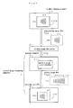
- Figs. 5 and 6 are flowcharts showing procedures of a medical image viewer process of the medical image view program 31 in the personal computer 3.
- the monochrome medical image data A(i, j) comprising an array, m rows and n columns, of pixels is read out from the medical image data server 2.
- a weighted average image data A'(i, j) which is a result of weighted averaging the medical image data A(i, j) along the minor axis is calculated from the medical image data A(i, j) and the minor axially weighted average weight b so that all the pixels of the medical image data A(i, j) appear in the display image.
- Fig. 7 illustrates structural concepts of the medical image data A(i, j) and the minor axially weighted average Image data A'(i, j).
- a ⁇ i ⁇ j A ⁇ i , j - 1 * b + A i ⁇ j * 1 - 2 * b + A ⁇ i , j + 1 * b
- the minor axially weighted average image data A'(i, j) Is calculated by weighted averaging the adjacent medical image data A(i,j-g),..., A(i, j+g).
- the minor axially weighted average weight may be determined depending on g.
- Step S4 the image column coordinate i is initialized to zero.
- Step S5 the LCD minor axial coordinate L is initialized to zero.
- a minor axially interpolated intermediate image data C(i, L) is calculated by linearly interpolating the minor axially weighted average image data A'(i, j) and the minor axial interpolation weight Wy(L) as shown in Fig. 9 and the following equation.
- C i ⁇ L A ⁇ i ⁇ jq * 1 - Wy L + A ⁇ ⁇ i , jq + 1 * Wy L
- Steps S9 and S10 the action at the steps 56 to S8 is repeated until L reaches (q-1).
- Steps S11 and S12 the action at the steps S5 to S10 is repeated until i reaches (n-1).
- the minor axially weighted average image data A'(i, j) is converted into the minor axially interpolated intermediate image data C(i, L).
- Step S15 the LCD major axial coordinate k is initialized to zero.
- Step S18 the LCD minor axial coordinate L Is initialized to zero.
- a display image data M'(k, L) is calculated by linearly interpolating the minor axially interpolated intermediate image data C(i, L) with the major axial interpolation weight Wx(k) as shown in Fig. 11 and the following equation.
- M ⁇ k ⁇ L C ip ⁇ L * 1 - Wx k + C ⁇ ip + 1 , L * Wx k
- Step S19 the action at Step S19 is repeated until L reaches (q-1) before the procedure advances to Step S22.
- Steps S22 and S23 the action at the steps S16 to S21 is repeated until k reaches (p*3-1) before the procedure advances to Step S24. Accordingly, as shown in Fig. 12 , the display image data M'(k, L) is obtained.
- the display image data M'(k, L) is subjected to the frequency enhancing process by weighted calculation at three points for improving the resolution along the minor axis, thus calculating the final display image data M(k, L). Accordingly, the final display image data M(k, L) is obtained as shown in Fig. 13 .
- M k ⁇ L M ⁇ ⁇ k , L - 1 * e + M ⁇ k ⁇ L * 1 - 2 * e + M ⁇ ⁇ k , L + 1 * e
- M(k, 0) M'(k, 0)
- M(k, q-1) M'(k, q-1)
- k 0, 1,..., p*3-1
- L 0, 1,..., q-1.
- e is a weighted factor for use In the frequency enhancing process as ranging, for example, from -0.1 to -0.2 in view of the balance with the direction of the major axis and the impression of a displayed image.
- the display image data M(k, L) is transferred from the personal computer 3 to the monochrome liquid crystal display 4.
- the monochrome liquid crystal display 4 drives the sub pixels of the LCD independently to display the display image data M(k, L) as shown in Fig. 14 .
- the image displaying apparatus and the image display program according to the present invention can favorably be used for increasing the efficiency of the action of doctors examining various medical photos including X-ray images, CT images, and MR images for diagnostic purposes.
Landscapes
- Engineering & Computer Science (AREA)
- Physics & Mathematics (AREA)
- General Physics & Mathematics (AREA)
- Theoretical Computer Science (AREA)
- Computer Hardware Design (AREA)
- Image Processing (AREA)
- Liquid Crystal Display Device Control (AREA)
Abstract
Description
- The present invention relates to an image displaying apparatus and an image display program and more particularly to an image displaying apparatus and an image display program arranged for driving the sub pixels independently in its LCD (liquid crystal display) to improve the resolution along the major axis of the LCD and displaying a reduced image while maintaining the aspect ratio of an original image.
- An image reducing method is known for reducing a great number of pixels in an image through simple sampling or operation sampling to produce an image of a small number of pixels (See Patent Citation 1).
- Meanwhile, a displaying apparatus is known which drives the three sub pixels of each pixel independently in its LCD (See Patent Citation 2).
- Patent Citation 1:
JP (Helsei)10-327402A - Patent Citation 2:
JP 2003-228337A - There is a demand, for example, for displaying a medical image recorded with an FPD (flat panel detector) of 4096x3328 pixel type on an LCD of 1600×1200 pixel type.
- Using the image reduction method of Patent Citation 1, a medical image of 4096x3328 pixels produced by the FPD is reduced to an image of 1477x1200 which can thus be displayed on the LCD of 1600×1200 pixel type. The number of pixels along the minor axis in the reduced image is set to 1200 because it corresponds to the number of pixels along the minor axis on the LCD. The number of pixels along the major axis in the reduced image is set to 1477 because the aspect ratio of the original image has to be maintained.
- Unfortunately, since the original image along either of the major axis and the minor axis is reduced from 2.774 (=4096/1477/1200) pixels to one pixel for the LCD, its resolution will significantly be declined.
- More specifically, it is essential for the diagnosis of breast cancer to identify a tiny pathological sign such as calcopherite of not greater than 100 µm. As the pitch of its pixels is generally 70 µm, the FPD has a desired degree of the resolution. However, since the pitch of pixels on LCD is equivalent to 194 (=70*2.774) µm of the pitch of pixels on the FPD, a desired degree of the resolution will hardly be maintained.
- Each pixel on the LCD of the monochrome liquid crystal display consists of three sub pixels aligned along the major axis of the LCD. The resolution along the major axis on the LCD can thus be improved by driving independently the three sub pixels such as in the display of
Patent Citation 2. - However, while the sub pixels are commonly rectangular in the shape, the image reducing method of Patent Citation 1 of which the shape of the pixels is square or circular falls to maintain the aspect ratio of the original image at the display.
- It is hence an object of the present invention to provide an image displaying apparatus and an image display program arranged for driving the sub pixels independently in the LCD to improve the resolution along the major axis of the LCD and displaying a reduced image while maintaining the aspect ratio of an original image.
- As a first aspect of the present invention, an image displaying apparatus is provided comprising: an image converting means for reducing and converting an original monochrome image which consists of an array, m rows and n columns, of pixels into a display image which consists of an array, q rows and (3*n*q/m) columns, of pixels where m, n, q, and P are natural numbers and m≤n, q<P, n/m<P/q, and m>q are given; and a monochrome liquid crystal display provided with a monochrome LCD, which is composed mainly of an array, q rows and P columns, of pixels for driving the sub pixels independently aligned along the rows of the monochrome LCD to display the display image on the LCD.
- The image displaying apparatus of the first aspect reduces and converts the original monochrome image which consists of an array, m rows and n columns, of pixels into a display image which consists of an array, q rows and (3*n*q/m) columns, of pixels. As the number of pixels along the row of the original monochrome image is (n*q/m) at the aspect ratio (n/m), the number of pixels along the row in the display image is three times greater than that of the original monochrome image at the aspect ratio (n/m) of the original monochrome image. With the three sub pixels of each pixel on the monochrome LCD aligned along the row and driven independently to display the display image, the number of pixels along the row on the monochrome LCD is expressed by (3*n*q/m)/3=(n*q/m). Accordingly, the aspect ratio of the display image is (n*q/m)/q=(n/m). In other words, the aspect ratio of the original image can be maintained.
- The resolution along the row is hence three times higher than that when the sub pixels are driven not independently. The pitch of the sub pixels on the LCD is equal at the conversion to n/(3*n*q/m)=m/(3*q) times greater than the pitch of the pixels on the FPD in view of the conversion into the pitch of pixels on the FPD. When the pitch of the pixels on the FPD is 70 µm with m=3328 and q=1200, for example, the pitch of the sub pixels on the LCD is equal to 65(=70*3328/(3*1200)) µm for the pitch of the pixels on the FPD in view of the conversion. Accordingly, the resolution of 100 µm needed for examining breast cancers can be achieved.
- As a second aspect of the present invention, an image display program for displaying an original monochrome image which consists of an array, m rows and n columns, of pixels on a monochrome LCD, which is composed of an array, q rows and P columns, of pixels, of a monochrome liquid crystal display where m, n, q, and P are natural numbers and m≤n, q<P, n/m<P/q, and m>q are given, is provided allowing a computer to act as an original monochrome image inputting means for inputting the original monochrome image from the outside, an image converting means for reducing and converting the original monochrome image into a display image which consists of an array, q rows and (3*n*q/m) columns, of pixels, and a display image outputting means for outputting the display image to the monochrome liquid crystal display in order to display the display image through independently driving the sub pixels of the monochrome LCD.
- The image display program of the second aspect reduces and converts the original monochrome image which consists of an array, m rows and n columns, of pixels into a display image which consists of an array, q rows and (3*n*q/m) columns, of pixels. As the number of pixels of the original monochrome Image is (n*q/m) at the aspect ratio (n/m), the number of pixels along the row in the display image is three times greater than that of the original monochrome image. With the three sub pixels of each pixel on the monochrome LCD aligned along the row and driven independently to display the display Image, the number of pixels along the row on the monochrome LCD is expressed by (3*n*q/m)/3=(n*q/m). Accordingly, the aspect ratio of the display image is (n*q/m)/q=(n/m). In other words, the aspect ratio of the original image can be maintained.
- The resolution along the row is hence three times higher than that when the sub pixels are driven not independently. The pitch of the sub pixels on the LCD is equal to n/(3*n*q/m)=m/(3*q) times greater than the pitch of the pixels on the FPD in view of the conversion into the pitch of pixels on the FPD. When the pitch of the pixels on the FPD is 70 µm with m=3328 and q=1200, for example, the pitch of the sub pixels on the LCD is equal to 65(=70*3328/(3*1200)) µm for the pitch of the pixels on the FPD in view of the conversion. Accordingly, the resolution of 100 µm needed for examining breast cancers can be achieved.
- The image displaying apparatus and the image display program according to the present invention allow the image to be reduced from an original image with the aspect ratio remaining unchanged and displayed on the LCD while the resolution along the major axis is improved.
- The present invention will be described in more detail referring to one preferred embodiment shown in the relevant drawings. It would be understood that the present invention is not limited to the embodiments.
-
Fig. 1 is a schematic view of a medicalimage displaying apparatus 1 illustratingEmbodiment 1. - The medical
image displaying apparatus 1 comprises apersonal computer 3 for carrying out a medical image viewer program 31 where, when m≤n, q<P, n/m<P/q, and m>q where m, n, q, and P are natural numbers, a monochrome medical image data A(i, j) which consists of an array, m rows and n columns, of pixels is entered and converted into a display image data M(k, L) which consists of a reduced array, q rows and - (3*n*q/m) columns, of pixels and a monochrome
liquid crystal display 4 equipped with a monochrome LCD panel which Is composed mainly of an array, q rows and P columns, of pixels for displaying the display image data M(k, L) through independently driving the sub pixels aligned along the rows of the monochrome LCD panel. - The monochrome medical image data A(i, j) has been recorded with an FPD in a medical imaging apparatus F which consists of an array, m rows and n columns, of pixels and saved in a medical image data server D.
- When m<n, the major axis of the medical image data A(i, j) is commonly determined to extend along the up-and-down direction of a subject to be examined thus allowing the major axis of the LCD to extend along the up-and-down direction. It is however assumed for ease of the description that both the medical image data A(i, j) and the LCD are extended longer along the horizontal direction.
-
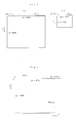
Fig. 2(a) illustrates a numerical example of the monochrome medical image data A(i, j) where m=3328 and n=4096. -
Fig. 2(b) illustrates a numerical example of the LCD where q=1200 and P=1600. -
Fig. 3 is an explanatory view showing the relationship between the LCD and the display image data M(k, L). - As n/m<P/q is given, the monochrome medical image data A(i, j) is reduced so that the minor axis of the LCD extends along the minor axis of the display image data M(k, L). When the aspect ratio n/m of the monochrome medical image data A(i, j) is maintained, the number p of pixels along the major axis of the display image data M(k, L) becomes smaller than the number P of pixels along the major axis of the LCD.
- For example, with m=3328, n=4096, q=1200, and P=1600, p=4096*1200/3328=1477 is established.
- As shown in
Fig. 4 , each pixel U in the LCD consists of three sub pixels u1, u2, and u3 aligned along the major axis of the LCD. Since the pixel U is arranged of a square shape, the shape of the sub pixels u1, u2, and u3 is rectangular. -
Figs. 5 and6 are flowcharts showing procedures of a medical image viewer process of the medical image view program 31 in thepersonal computer 3. - At Step S0, the monochrome medical image data A(i, j) comprising an array, m rows and n columns, of pixels is read out from the medical
image data server 2. - At Step S1, a reduction rate ry=m/q along the minor axis is calculated from the number m of pixels along the minor axis of the monochrome medical Image data A(i, j) and the number q of pixels along the minor axis on the LCD. For example, ry=2.774 is given with m=3328 and q=1200.
- At Step S2, a minor axially weighted average weight b=(ry-1)*B is calculated from the reduction rate ry along the minor axis and an adjusting factor B. For example, b=0.2129 is given when ry=2.774 and B=0.12. This allows an operator to control the appearance (with image noises) of the display image through adjusting the adjusting factor B.
- At Step S3, a weighted average image data A'(i, j) which is a result of weighted averaging the medical image data A(i, j) along the minor axis is calculated from the medical image data A(i, j) and the minor axially weighted average weight b so that all the pixels of the medical image data A(i, j) appear in the display image.
-
Fig. 7 illustrates structural concepts of the medical image data A(i, j) and the minor axially weighted average Image data A'(i, j). - As apparent from
Fig. 8 and the following equation, the minor axially weighted average image data A'(i, j) is calculated by weighted averaging the three adjacent medical image data A(i, j-1), A(i, j), and A(i, j+1), because the minimum integer which is greater than the reduction rate ry=2.774 along the minor axis is 3.
where A'(i, 0)=A(i, 0) and A'(i, m-1)=A(i, m-1).
i=0, 1,..., n-1, j=0, 1,..., m-1. - In common, when the integer which is greater than the reduction rate ry along the minor axis is (2*g+1), the minor axially weighted average image data A'(i, j) Is calculated by weighted averaging the adjacent medical image data A(i,j-g),..., A(i, j+g). The minor axially weighted average weight may be determined depending on g.
- At Step S4, the image column coordinate i is initialized to zero.
- At Step S5, the LCD minor axial coordinate L is initialized to zero.
- At Step S6, an image reference coordinates jq=int(L*ry) along the minor axis is calculated with the LCD minor axial coordinate L,
- At Step S7, a minor axial interpolation weight Wy(L)=(L*ry)-jq is calculated.
- At Step S8, a minor axially interpolated intermediate image data C(i, L) is calculated by linearly interpolating the minor axially weighted average image data A'(i, j) and the minor axial interpolation weight Wy(L) as shown in
Fig. 9 and the following equation.
- At Steps S9 and S10, the action at the steps 56 to S8 is repeated until L reaches (q-1).
- At Steps S11 and S12, the action at the steps S5 to S10 is repeated until i reaches (n-1).
- As described and shown in
Fig. 10 , the minor axially weighted average image data A'(i, j) is converted into the minor axially interpolated intermediate image data C(i, L). - Referring to
Fig. 6 , at Step S13, the number p=n/ry of pixels along the major axis of the LCD used for actually displaying along the major axis on the LCD is calculated. For example, p=1477 is established when n=4096 and ry=2.774. - At Step S14, a reduction rate rx=n/(p*3) along the major axis is calculated from the number (p*3) of sub pixels which is a result of multiplying the number p of pixels by three for independently driving the three sub pixels along the major axis in each pixel of the LCD. For example, rx=0.9244 is established when n=4096 and p=1477.
- At Step S15, the LCD major axial coordinate k is initialized to zero.
- At Step S16, a major axial image reference coordinate ip=int(k*rx) corresponding to the major axial LCD coordinate k is calculated.
- At Step S17, a major axial interpolation weight Wx(k)=(k*rx)-ip is calculated.
- At Step S18, the LCD minor axial coordinate L Is initialized to zero.
- At Step 519, a display image data M'(k, L) is calculated by linearly interpolating the minor axially interpolated intermediate image data C(i, L) with the major axial interpolation weight Wx(k) as shown in
Fig. 11 and the following equation.
- At Steps S20 and S21, the action at Step S19 is repeated until L reaches (q-1) before the procedure advances to Step S22.
- At Steps S22 and S23, the action at the steps S16 to S21 is repeated until k reaches (p*3-1) before the procedure advances to Step S24. Accordingly, as shown in
Fig. 12 , the display image data M'(k, L) is obtained. - At Step S24, the display image data M'(k, L) is subjected to the frequency enhancing process by weighted calculation at three points for improving the resolution along the minor axis, thus calculating the final display image data M(k, L). Accordingly, the final display image data M(k, L) is obtained as shown in
Fig. 13 .
where M(k, 0)=M'(k, 0), M(k, q-1)=M'(k, q-1), k=0, 1,..., p*3-1 and L=0, 1,..., q-1. Also, e is a weighted factor for use In the frequency enhancing process as ranging, for example, from -0.1 to -0.2 in view of the balance with the direction of the major axis and the impression of a displayed image. - At Step S25, the display image data M(k, L) is transferred from the
personal computer 3 to the monochromeliquid crystal display 4. - The monochrome
liquid crystal display 4 drives the sub pixels of the LCD independently to display the display image data M(k, L) as shown inFig. 14 . - The advantages of the medical
image displaying apparatus 1 with the medical image viewer program 31 ofEmbodiment 1 are as follows. - (1) The number of the sub pixels along the major axis of the LCD to be actually used for display is (p*3) which is equivalent to the number (n*q/m) of the pixels in view of the conversion into the number of pixels. Accordingly, the aspect ratio of the display image is expressed by (n*q/m)/q=(n/m). More particularly, the aspect ratio of the medical image data A(i, j) can be maintained.
- (2) The resolution along the major axis is three times greater than that when the sub pixels are driven not independently. The pitch of the sub pixels on the LCD Is equal at the conversion to n/(3*n*q/m)=m/(3*q) times greater than the pitch of the pixels on the FPD in view of the conversion into the pitch of pixels on the FPD. For example, when the pitch of the pixels on the FPD is 70 µm with m=3328 and q=1200, the pitch of the sub pixels on the LCD is equal to 65 (=70*3328/(3*1200)) µm for the pitch of the pixels on the FPD In view of the conversion. Accordingly, the resolution of 100 µm needed for examining breast cancers can be achieved.
- The image displaying apparatus and the image display program according to the present invention can favorably be used for increasing the efficiency of the action of doctors examining various medical photos including X-ray images, CT images, and MR images for diagnostic purposes.
-
-
Fig. 1 is a schematic explanatory view of a medical image displayingapparatus showing Embodiment 1 of the present invention; -
Fig. 2 is an explanatory view showing an array of pixels in a medical image data and an array of pixels on an LCD; -
Fig. 3 is an explanatory view showing a reduced image on the LCD; -
Fig. 4 is a partially enlarged view of sub pixels in the LCD; -
Fig. 5 is a flowchart of steps of a medical image viewer processing action according toEmbodiment 1; -
Fig. 6 is a flowchart following that ofFig. 5 ; -
Fig. 7 is an explanatory view showing an array of pixels in a medical image data and an array of pixels in its minor axially weighted average image; -
Fig. 8 is an explanatory view of an action of calculating the minor axially weighted average; -
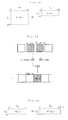
Fig. 9 is an explanatory view of a minor axially linear interpolating action; -
Fig. 10 is an explanatory view showing an array of pixels in the minor axially weighted average image and an array of pixels in its minor axially interpolated intermediate image; -
Fig. 11 is an explanatory view of a major axially linear interpolating action; -
Fig. 12 is an explanatory view showing an array of pixels in the minor axially interpolated intermediate image and an array of pixels in the display image; -
Fig. 13 is an explanatory view of an action of frequency enhancing the display image; and -
Fig. 14 is an explanatory view showing an array of pixels in the display image and its actual display on the display screen. - 1: Medical image displaying apparatus, 3: Personal computer, 4: Monochrome liquid crystal display, 31: Medical image viewer program.
- Additional features of the invention are discussed in the following clauses:
- 1. An image displaying apparatus comprising:
- an image converting means for reducing and converting an original monochrome image which consists of an array, m rows and n columns, of pixels into a display image which consists of an array, q rows and (3*n*q/m) columns, of pixels where m, n, q, and P are natural numbers and m≤n, q<P, n/m<P/q, and m>q are given; and
- a monochrome liquid crystal display provided with a monochrome LCD composed of an array, q rows and P columns, of pixels for driving the sub pixels independently aligned along the row of the monochrome LCD to display the display image on the LCD.
- 2. An image display program for displaying an original monochrome image which consists of an array, m rows and n columns, of pixels on a monochrome LCD of a monochrome liquid crystal display which is composed of an array, q rows and P columns, of pixels where m, n, q, and P are natural numbers and m≤n, q<P, n/m<P/q, and m>q are given, allowing a computer to act as:
- an original monochrome image inputting means for inputting the original monochrome image from the outside;
- an image converting means for reducing and converting the original monochrome image into a display image which consists of an array, q rows and (3*n*q/m) columns, of pixels; and
- a display image outputting means for outputting the display image to the monochrome liquid crystal display in order to display the display image through independently driving the sub pixels of the monochrome LCD.
Claims (2)
- An image displaying apparatus, which maintains the aspect ratio of an original monochrome image, comprising:an image converting means adapted to convert the original monochrome image which consists of an array, m rows and n columns, of pixels into a display image which consists of an array, q rows and (3*n*q/m) columns, of pixels where m, n, q, and P are natural numbers and m≤n,q<P,n/m<P/q, and m>q are given; anda monochrome liquid crystal display provided with a monochrome LCD composed of an array, q rows and P columns, of pixels of square shape, each pixel consisting of three rectangular sub pixels aligned along the row of monochrome LCD, for driving the sub pixels independently to display the display image on the LCD.
- An image display program, which maintains the aspect ratio of an original monochrome image, for displaying the original monochrome image which consists of an array, m rows and n columns, of pixels on a monochrome LCD of a monochrome liquid crystal display which is composed of an array, q rows and P columns, of pixels of square shape, each pixel consisting of three rectangular sub pixels aligned along the row of monochrome LCD for driving the sub pixels independently to display the display image on the LCD where m,n,q, and P are natural numbers and m≤n,q<P,n/m<P/q, and m>q are given, allowing a computer to act as:an original monochrome image inputting means for inputting the original monochrome image from the outside;an image converting means for converting the original monochrome image into a display image which consists of an array, q rows and (3*n*q/m) columns, of pixels; anda display image outputting means for outputting the display image to the monochrome liquid crystal display in order to display the display image through independently driving the sub pixels of the monochrome LCD.
Priority Applications (1)
| Application Number | Priority Date | Filing Date | Title |
|---|---|---|---|
| EP12171736.7A EP2500899B1 (en) | 2006-08-30 | 2006-08-30 | Image displaying apparatus and image display program |
Applications Claiming Priority (2)
| Application Number | Priority Date | Filing Date | Title |
|---|---|---|---|
| EP06797016A EP2058793A4 (en) | 2006-08-30 | 2006-08-30 | IMAGE DISPLAY DEVICE AND IMAGE DISPLAY PROGRAM |
| EP12171736.7A EP2500899B1 (en) | 2006-08-30 | 2006-08-30 | Image displaying apparatus and image display program |
Related Parent Applications (1)
| Application Number | Title | Priority Date | Filing Date |
|---|---|---|---|
| EP06797016A Division EP2058793A4 (en) | 2006-08-30 | 2006-08-30 | IMAGE DISPLAY DEVICE AND IMAGE DISPLAY PROGRAM |
Publications (3)
| Publication Number | Publication Date |
|---|---|
| EP2500899A2 true EP2500899A2 (en) | 2012-09-19 |
| EP2500899A3 EP2500899A3 (en) | 2015-04-01 |
| EP2500899B1 EP2500899B1 (en) | 2017-11-08 |
Family
ID=46705104
Family Applications (1)
| Application Number | Title | Priority Date | Filing Date |
|---|---|---|---|
| EP12171736.7A Active EP2500899B1 (en) | 2006-08-30 | 2006-08-30 | Image displaying apparatus and image display program |
Country Status (1)
| Country | Link |
|---|---|
| EP (1) | EP2500899B1 (en) |
Family Cites Families (3)
| Publication number | Priority date | Publication date | Assignee | Title |
|---|---|---|---|---|
| JP3742167B2 (en) * | 1996-12-18 | 2006-02-01 | 株式会社東芝 | Image display control device |
| US20020122049A1 (en) * | 2001-03-02 | 2002-09-05 | Eastman Kodak Company | Light-producing display having spaced apart tiles |
| JP2005062833A (en) * | 2003-07-29 | 2005-03-10 | Seiko Epson Corp | Color filter, color image display device, and electronic apparatus |
-
2006
- 2006-08-30 EP EP12171736.7A patent/EP2500899B1/en active Active
Non-Patent Citations (1)
| Title |
|---|
| None |
Also Published As
| Publication number | Publication date |
|---|---|
| EP2500899A3 (en) | 2015-04-01 |
| EP2500899B1 (en) | 2017-11-08 |
Similar Documents
| Publication | Publication Date | Title |
|---|---|---|
| US8144191B2 (en) | Endoscope visual imaging and processing apparatus | |
| JP5038304B2 (en) | Ultrasonic diagnostic equipment | |
| KR20140103171A (en) | Image processing device, image processing system, image processing method, and image processing program | |
| US8594466B2 (en) | Image data converting device, method for converting image data, program and storage medium | |
| JP2010039445A (en) | Multiple image display device and image processor | |
| US6704463B1 (en) | Interpolation/decimation apparatus, interpolation/decimation method and image display apparatus | |
| KR20140107469A (en) | Image processing device, image processing system, image processing method, and image processing program | |
| JP2012205619A (en) | Image processor, control device, endoscope apparatus, image processing method, and image processing program | |
| JP2016057990A (en) | Display panel driver, display device, image processing device, and image processing method | |
| EP2058793A1 (en) | Image display device and image display program | |
| WO2009122863A1 (en) | Image display system and image display program | |
| CN114677268A (en) | X-ray image processing device and X-ray image processing method | |
| EP1833036A2 (en) | Image display apparatus and method, program therefor, and recording medium having recorded thereon the same | |
| EP2500899B1 (en) | Image displaying apparatus and image display program | |
| EP3235418A1 (en) | Display control device and endoscope system | |
| DE69315377T2 (en) | Method and device for displaying multiple images on a display unit by performing filtering | |
| Harris et al. | Display and analysis of tomographic volumetric images utilizing a vari-focal mirror | |
| JP2011235107A (en) | Medical image display device and medical image display program | |
| JP6855333B2 (en) | Image processing equipment and computer programs | |
| Ichikawa et al. | A new resolution enhancement technology using the independent sub-pixel driving for the medical liquid crystal displays | |
| JPWO2010087264A1 (en) | Image display system and image display program | |
| JP2007190208A (en) | Comparative interpretation support device | |
| Ichikawa et al. | Development of a new resolution enhancement technology for medical liquid crystal displays | |
| JP2006079590A (en) | Image processor | |
| JPH07134576A (en) | Image enlarging device |
Legal Events
| Date | Code | Title | Description |
|---|---|---|---|
| PUAI | Public reference made under article 153(3) epc to a published international application that has entered the european phase |
Free format text: ORIGINAL CODE: 0009012 |
|
| 17P | Request for examination filed |
Effective date: 20120727 |
|
| AC | Divisional application: reference to earlier application |
Ref document number: 2058793 Country of ref document: EP Kind code of ref document: P |
|
| AK | Designated contracting states |
Kind code of ref document: A2 Designated state(s): DE FR GB |
|
| RAP1 | Party data changed (applicant data changed or rights of an application transferred) |
Owner name: NATIONAL UNIVERSITY CORPORATION NAGOYA UNIVERSITY Owner name: JVC KENWOOD CORPORATION |
|
| PUAL | Search report despatched |
Free format text: ORIGINAL CODE: 0009013 |
|
| AK | Designated contracting states |
Kind code of ref document: A3 Designated state(s): DE FR GB |
|
| RIC1 | Information provided on ipc code assigned before grant |
Ipc: G09G 3/36 20060101AFI20150220BHEP Ipc: H04N 5/66 20060101ALI20150220BHEP Ipc: G09G 5/391 20060101ALI20150220BHEP Ipc: G09G 5/20 20060101ALI20150220BHEP Ipc: G06T 3/40 20060101ALI20150220BHEP Ipc: H04N 1/387 20060101ALI20150220BHEP Ipc: G02F 1/13 20060101ALI20150220BHEP Ipc: G09G 3/20 20060101ALI20150220BHEP Ipc: G09G 5/00 20060101ALI20150220BHEP |
|
| GRAP | Despatch of communication of intention to grant a patent |
Free format text: ORIGINAL CODE: EPIDOSNIGR1 |
|
| INTG | Intention to grant announced |
Effective date: 20170524 |
|
| GRAS | Grant fee paid |
Free format text: ORIGINAL CODE: EPIDOSNIGR3 |
|
| GRAA | (expected) grant |
Free format text: ORIGINAL CODE: 0009210 |
|
| AC | Divisional application: reference to earlier application |
Ref document number: 2058793 Country of ref document: EP Kind code of ref document: P |
|
| AK | Designated contracting states |
Kind code of ref document: B1 Designated state(s): DE FR GB |
|
| REG | Reference to a national code |
Ref country code: GB Ref legal event code: FG4D |
|
| REG | Reference to a national code |
Ref country code: DE Ref legal event code: R096 Ref document number: 602006054084 Country of ref document: DE |
|
| REG | Reference to a national code |
Ref country code: FR Ref legal event code: PLFP Year of fee payment: 13 |
|
| REG | Reference to a national code |
Ref country code: DE Ref legal event code: R097 Ref document number: 602006054084 Country of ref document: DE |
|
| PLBE | No opposition filed within time limit |
Free format text: ORIGINAL CODE: 0009261 |
|
| STAA | Information on the status of an ep patent application or granted ep patent |
Free format text: STATUS: NO OPPOSITION FILED WITHIN TIME LIMIT |
|
| 26N | No opposition filed |
Effective date: 20180809 |
|
| PGFP | Annual fee paid to national office [announced via postgrant information from national office to epo] |
Ref country code: DE Payment date: 20250702 Year of fee payment: 20 |
|
| PGFP | Annual fee paid to national office [announced via postgrant information from national office to epo] |
Ref country code: GB Payment date: 20250703 Year of fee payment: 20 |
|
| PGFP | Annual fee paid to national office [announced via postgrant information from national office to epo] |
Ref country code: FR Payment date: 20250703 Year of fee payment: 20 |