EP2500743B1 - System and method for three-dimensional geolocation of emitters based on energy measurements - Google Patents
System and method for three-dimensional geolocation of emitters based on energy measurements Download PDFInfo
- Publication number
- EP2500743B1 EP2500743B1 EP12159186.1A EP12159186A EP2500743B1 EP 2500743 B1 EP2500743 B1 EP 2500743B1 EP 12159186 A EP12159186 A EP 12159186A EP 2500743 B1 EP2500743 B1 EP 2500743B1
- Authority
- EP
- European Patent Office
- Prior art keywords
- signal strength
- emitter
- locations
- location
- strength measurements
- Prior art date
- Legal status (The legal status is an assumption and is not a legal conclusion. Google has not performed a legal analysis and makes no representation as to the accuracy of the status listed.)
- Not-in-force
Links
- 238000005259 measurement Methods 0.000 title claims description 88
- 238000000034 method Methods 0.000 title claims description 41
- 238000012545 processing Methods 0.000 claims description 11
- 230000000694 effects Effects 0.000 claims description 8
- 238000005562 fading Methods 0.000 claims description 6
- 230000008569 process Effects 0.000 claims description 6
- 239000011159 matrix material Substances 0.000 description 24
- 238000004891 communication Methods 0.000 description 17
- 239000013598 vector Substances 0.000 description 12
- 238000004088 simulation Methods 0.000 description 8
- 230000006870 function Effects 0.000 description 7
- 230000000295 complement effect Effects 0.000 description 2
- 238000012986 modification Methods 0.000 description 2
- 230000004048 modification Effects 0.000 description 2
- 230000003287 optical effect Effects 0.000 description 2
- 238000005307 time correlation function Methods 0.000 description 2
- 238000000342 Monte Carlo simulation Methods 0.000 description 1
- 230000001413 cellular effect Effects 0.000 description 1
- 238000004590 computer program Methods 0.000 description 1
- 238000007796 conventional method Methods 0.000 description 1
- 238000001514 detection method Methods 0.000 description 1
- 238000010586 diagram Methods 0.000 description 1
- 238000005516 engineering process Methods 0.000 description 1
- 230000006855 networking Effects 0.000 description 1
Images


Classifications
-
- G—PHYSICS
- G01—MEASURING; TESTING
- G01S—RADIO DIRECTION-FINDING; RADIO NAVIGATION; DETERMINING DISTANCE OR VELOCITY BY USE OF RADIO WAVES; LOCATING OR PRESENCE-DETECTING BY USE OF THE REFLECTION OR RERADIATION OF RADIO WAVES; ANALOGOUS ARRANGEMENTS USING OTHER WAVES
- G01S11/00—Systems for determining distance or velocity not using reflection or reradiation
- G01S11/02—Systems for determining distance or velocity not using reflection or reradiation using radio waves
- G01S11/06—Systems for determining distance or velocity not using reflection or reradiation using radio waves using intensity measurements
-
- G—PHYSICS
- G01—MEASURING; TESTING
- G01S—RADIO DIRECTION-FINDING; RADIO NAVIGATION; DETERMINING DISTANCE OR VELOCITY BY USE OF RADIO WAVES; LOCATING OR PRESENCE-DETECTING BY USE OF THE REFLECTION OR RERADIATION OF RADIO WAVES; ANALOGOUS ARRANGEMENTS USING OTHER WAVES
- G01S5/00—Position-fixing by co-ordinating two or more direction or position line determinations; Position-fixing by co-ordinating two or more distance determinations
- G01S5/02—Position-fixing by co-ordinating two or more direction or position line determinations; Position-fixing by co-ordinating two or more distance determinations using radio waves
- G01S5/0249—Determining position using measurements made by a non-stationary device other than the device whose position is being determined
-
- G—PHYSICS
- G01—MEASURING; TESTING
- G01S—RADIO DIRECTION-FINDING; RADIO NAVIGATION; DETERMINING DISTANCE OR VELOCITY BY USE OF RADIO WAVES; LOCATING OR PRESENCE-DETECTING BY USE OF THE REFLECTION OR RERADIATION OF RADIO WAVES; ANALOGOUS ARRANGEMENTS USING OTHER WAVES
- G01S5/00—Position-fixing by co-ordinating two or more direction or position line determinations; Position-fixing by co-ordinating two or more distance determinations
- G01S5/02—Position-fixing by co-ordinating two or more direction or position line determinations; Position-fixing by co-ordinating two or more distance determinations using radio waves
- G01S5/0284—Relative positioning
- G01S5/0289—Relative positioning of multiple transceivers, e.g. in ad hoc networks
Definitions
- the present invention embodiments pertain to determining locations of emitters.
- the present invention embodiments pertain to determining locations of radio frequency (RF) emitters in a three-dimensional space based on energy or received signal strength (RSS) measurements of the emitters at various locations.
- RF radio frequency
- RSS received signal strength
- RSS-based techniques for geolocation of a radio frequency (RF) emitter are commonly based on measurements of a received signal strength (RSS) of signals transmitted from the emitter. Accordingly, this RSS-based technique may also be referred to as an energy-based technique.
- the received signal strength (RSS) is usually integrated over the duration of the transmitted signal in order to obtain a signal energy measurement and enhance signal to noise ratio. Since the transmitted radio frequency (RF) signal attenuates during propagation through space, the received signal strength (RSS) of the signal may be used to estimate the distance from the receiver to the emitter.
- this technique may not be very accurate due to multipath fading and shadowing effects that may significantly distort the expected received signal strength (RSS).
- the received signal strength (RSS) or energy-based geolocation technique may employ a radio frequency (RF) propagation map of the environment.
- the map is basically a database with information created from known terrain data and learned from observed energy measurements at different combinations of emitter and receiver locations.
- the improved geolocation technique determines the best fit in the energy space to potential emitter locations based on the radio frequency (RF) propagation map.
- RF radio frequency
- US 5 767 804 A discloses an integrated radio direction finding and GPS receiver tracking system.
- a transceiver device is attached to an object to be located.
- the transceiver device transmits a signal.
- the transmitted signal is received by a tracking unit.
- the tracking unit uses the received signal to determine the range and bearing of the object from the tracking unit.
- a position generating system is attached to the tracking unit to generate the position information of the tracking unit.
- the range and bearing of the object from the tracking unit and the position information of the tracking unit are transmitted from the tracking unit to a base station.
- the base station processes the range and bearing of the transceiver device from the tracking unit and the position information of the tracking unit to calculate the position of the object to be located.
- WO 2007/063,537 A1 discloses a method and system for locating an unknown emitter.
- the method for locating an unknown emitter comprises launching from a platform a vehicle equipped with an RF receiver/transmitter; and gathering measurements of electromagnetic signal emitted by the unknown emitter and collected by said platform and said vehicle, thereby enabling Time-of-Arrival processing of said measurements for deriving the location of the unknown emitter.
- US 6 141 558 A discloses that after determining a distressed mobile subscriber communication unit is within a communication coverage area of a base transceiver station, a mobile positioned at a first location uses a rotating directional antenna to force mobile subscriber communication units including the mobile subscriber communication unit to hand off communication.
- a first direction of the directional antenna is noted.
- the same procedure is repeated at another location and a second direction of the directional antenna is noted.
- a triangulation process using the first and second direction of the directional antenna and the first and second locations, reveal the location of the mobile subscriber communication unit.
- An embodiment of the present invention pertains to a three-dimensional (3-D) energy-based emitter geolocation technique that determines the geolocation of a radio frequency (RF) emitter based on energy or received signal strength (RSS) of transmitted signals.
- the technique may be employed with small unmanned air vehicles (UAV), and obtains reliable geolocation estimates of radio frequency (RF) emitters of interest.
- UAV small unmanned air vehicles
- the invention also includes a program product apparatus comprising a computer readable medium with computer program logic recorded thereon for locating an emitter within an area, said program product apparatus further comprising a location module to process measurements of signals transmitted by said emitter and obtained at a plurality of different locations within said area and to determine a three-dimensional location of said emitter within said area based on relationships of distances between said emitter and each of said plurality of locations, wherein said measurements are proportional to said distances.
- the location module includes a variable module to determine said three-dimensional location by solving a set of simultaneous equations relating to said distances, wherein said set of simultaneous equations includes unknown variables representing coordinates of said three-dimensional location of said emitter within said area.
- the variable module can solve said set of simultaneous equations using a Least Mean Square technique.
- the measurements can include energy measurements of said signals transmitted by said emitter.
- the measurements can also include a received signal strength of said signals transmitted by said emitter.
- the location module can includes a parameter module to determine a parameter for said set of simultaneous equations based on said energy measurements.
- the parameter can be based on a ratio of said energy measurements.
- the technique of present invention embodiments provides the simplicity and the performance robustness required by a low-cost, compact system.
- UAV small unmanned air vehicle
- RSS received signal strength
- RF radio frequency
- LOS Line-of-Sight
- Each RSS measurement that feeds the geolocation algorithm is the measurement with the maximum signal to noise ratio selected from a block of consecutive RSS data (which is referred to herein as the maximum signal to noise ratio (MSNR) rule).
- MSNR maximum signal to noise ratio
- the block size can be determined using the assessment of the spaced-frequency spaced-time correlation function of the propagation channel.
- the MSNR rule further enhances the quality of the RSS measurements used by the geolocation algorithm.
- UAV unmanned air vehicle
- Embodiments of the present invention pertain to a three-dimensional (3-D) energy-based geolocation technique that obtains reliable geolocation estimates of a radio frequency (RF) emitter based on energy or received signal strength (RSS) of transmitted signals.
- RF radio frequency
- the geolocation of a radio frequency (RF) emitter is a critical need for many applications.
- the technique of present invention embodiments may be employed with unmanned air vehicles (UAV) that are usually small, utilized for low altitudes, and employ typical guidance technologies for operation (e.g., following pre-planned or manually provided paths or waypoints). These types of vehicles are well suited for enabling three-dimensional (3-D) geolocation of radio frequency (RF) emitters of interest.
- UAV unmanned air vehicles
- a radio frequency (RF) emitter 120 An example environment for determining the geolocation of a radio frequency (RF) emitter in a three-dimensional space is illustrated in Fig. 1 .
- the environment includes a radio frequency (RF) emitter 120, and a mobile sensor 100 (e.g., an unmanned air vehicle (UAV) or other platform with a radio frequency (RF) sensor, etc.).
- the mobile sensor travels along a pre-planned path 110 (e.g., a pre-planned flight path in the case of an unmanned air vehicle (UAV)).
- Mobile sensor 100 includes an antenna 130 that receives signals from radio frequency (RF) emitter 120 in order to measure the strength of those signals as described below.
- the radio frequency (RF) emitter and mobile sensor are located within a three-dimensional space of the environment (e.g., defined by X, Y, and Z axes as illustrated in Fig. 1 ). Locations within the three-dimensional space may be represented by coordinates that indicate a position along each of the respective X, Y, and Z axes.
- radio frequency (RF) emitter 120 is positioned at an unknown location (x, y, z) within the three-dimensional space, while mobile sensor 100 receives signals transmitted from the radio frequency (RF) emitter at known locations along path 110 within the three-dimensional space (e.g., locations (xo, y 0 , zo), (x 1 , y 1 , z 1 ), and (x 2 , y 2 , z 2 ) as viewed in Fig. 1 ).
- the Z axis represents the height or altitude, and indicates the offset between the mobile sensor and pre-planned path 110 (e.g., distances z 0 , z 1 , z 2 as viewed in Fig. 1 ).
- Mobile sensor 100 measures at selected locations (e.g., (x 0 , y 0 , z 0 ), (x 1 , y 1 , z 1 ), and (x 2 , y 2 , z 2 ) as viewed in Fig. 1 ) the received signal strength (RSS) (e.g., p 0 , p 1 , p 2 as viewed in Fig. 1 ) of radio frequency (RF) signals emitted by emitter 120.
- the received signal strength (RSS) at each location is proportional to the distance (e.g., r 0 , r 1 , r 2 as viewed in Fig. 1 ) between that location and radio frequency (RF) emitter 120.
- the received signal strength (RSS) measurement can be viewed as a special case of the signal energy in which only a single signal sample is used for the measurement at each location.
- Each RSS measurement that feeds the geolocation algorithm is the measurement with the maximum signal to noise ratio selected from a block of consecutive RSS data (which is referred to herein as the maximum signal to noise ratio (MSNR) rule).
- MSNR maximum signal to noise ratio
- the block size can be determined using the assessment of the spaced-frequency spaced-time correlation function of the propagation channel.
- the received signal strength (RSS) measurements may be collected by using an unmanned air vehicle (UAV) or other platform along a flight or other pre-planned path, or by using plural unmanned air vehicles (UAV) or other platforms each collecting a measurement at one or more locations along that path.
- UAV unmanned air vehicle
- UAV unmanned air vehicle
- UAV unmanned air vehicles
- measurements from plural locations may be ascertained via a single platform traveling to different locations, or via plural platforms each positioned at different locations and networking or otherwise sharing the collected data for the geolocation determination.
- a Least Mean Square (LMS) technique is preferably employed to determine the location of radio frequency (RF) emitter 120 as described below.
- RF radio frequency
- Fig. 1 indicates measurements at certain locations (e.g., (x 0 , y 0 , z 0 ), (x 1 , y 1 , z 1 ), and (x 2 , y 2 , z 2 ) as viewed in Fig.
- RSS received signal strength
- Present invention embodiments resolve the location of radio frequency (RF) emitter 120 by estimating the energy or received signal strength (RSS) of signals emitted from emitter 120 via the received signal strength (RSS) measurements ascertained from plural locations (e.g., p 0 , p 1 , p 2 measured at locations (x 0 , y 0 , z 0 ), (x 1 , y 1 , z 1 ), and (x 2 , y 2 , z 2 ) as viewed in Fig. 1 ) along path 110.
- p 0 , p 1 , p 2 measured at locations (x 0 , y 0 , z 0 ), (x 1 , y 1 , z 1 ), and (x 2 , y 2 , z 2 ) as viewed in Fig. 1 ) along path 110.
- the received signal strength (RSS) measurements are each proportional to the distance between the location of that measurement and radio frequency (RF) emitter 120 (e.g., r 0 , r 1 , r 2 as viewed in Fig. 1 ) as described above.
- the measurements are utilized in a set of simultaneous equations to determine the location of the radio frequency (RF) emitter within the three-dimensional space as described below.
- An example system 200 for determining the geolocation of a radio frequency (RF) emitter according to an embodiment of the present invention is illustrated in Fig. 2 .
- system 200 preferably resides on mobile sensor 100 ( Fig. 1 ) to measure the received signal strength (RSS) and determine the geolocation of the radio frequency (RF) emitter.
- system 200 may be remote from the mobile sensor and receive the received signal strength (RSS) measurements for the geolocation determination.
- system 200 includes antenna 130, a receiver 210, and a processing device 230.
- Antenna 130 is preferably implemented by an omni-directional antenna, and directs received signals into receiver 210.
- the antenna may be implemented by any conventional or other antenna configurable to receive the signals emitted from radio frequency (RF) emitter 120.
- Receiver 210 includes a radiometer or energy detector 220 that provides an energy measure (e.g., received signal strength (RSS)) of the signals received from antenna 130.
- RSS received signal strength
- the receiver may be implemented by any conventional or other receiving device capable of receiving the emitted radio frequency (RF) signals, while the radiometer may be implemented by any conventional or other device to measure the energy or received signal strength (RSS) of a received signal. Based on the MSNR rule, the selected, received signal strength (RSS) measurements are provided to processing device 230 to determine the geolocation of radio frequency (RF) emitter 120 as described below.
- Processing device 230 may include a processor 250, a memory 260, and an interface unit 270.
- Processor 250 determines the geolocation of radio frequency (RF) emitter 120 based on the measurements received from receiver 210 and provides corresponding geolocation data 240.
- the processor includes one or more location modules to determine the location of radio frequency (RF) emitter 120 from a set of simultaneous equations incorporating a Least Mean Square (LMS) technique as described below.
- the processor may be implemented by any conventional or other computer or processing unit (e.g., a microprocessor, a microcontroller, systems on a chip (SOCs), fixed or programmable logic, etc.), where the one or more location modules may be implemented by any combination of any quantity of software and/or hardware modules or units.
- Memory 260 may be included within or external of processor 250, and may be implemented by any conventional or other memory unit with any type of memory (e.g., random access memory (RAM), read only memory (ROM), etc.).
- the memory may store the one or more location modules for execution by processor 250, and data for performing the geolocation technique of present invention embodiments.
- Interface unit 270 enables communication between system 200 and other devices or systems, and may be implemented by any conventional or other communications device (e.g., wireless communications device, etc.).
- processor 250 determines the geolocation of a radio frequency (RF) emitter based on received signal strength (RSS) at various locations.
- RF radio frequency
- RSS received signal strength
- one or more mobile sensors 100 measure received signal strength (RSS) of signals emitted from radio frequency (RF) emitter 120 at one or more locations (e.g., a quantity of locations from 0 through N as described below) along path 110 at step 300.
- RSS received signal strength
- a set of simultaneous equations to determine the geolocation of the radio frequency (RF) emitter based on the received signal strength (RSS) measurements are determined, and converted into matrix form.
- the location of radio frequency (RF) emitter 120 within the three-dimensional space may be represented by the coordinates (x, y, z), while the position of mobile sensor 100 ascertaining a measurement at an i th location along path 110 may be represented by the coordinates (x i , y i , z i ).
- the terms of the above equation (Equation 4) may be converted to matrix form and employ the parameter, ⁇ i (from Equation 5).
- the determined values for x, y, and z represent the coordinates (or location) of radio frequency (RF) emitter 120 within the three-dimensional space, while the determined value for r 0 2 represents the square of the distance between radio frequency (RF) emitter 120 and the known reference location (e.g., at coordinates x 0 , y 0 , and z 0 within the three-dimensional space) of mobile sensor 100.
- the parameter, ⁇ i , of matrix P may be estimated based on the measurements of received signal strength (RSS) obtained by mobile sensor 100.
- RSS received signal strength
- the received signal power, p i , at the i th location along path 110 is inversely proportional to the square law of the distance, r i , between the mobile sensor (e.g., unmanned air vehicle (UAV)) and the radio frequency (RF) emitter.
- At least four independent equations are required to determine the four unknown variables (e.g., r 0 2 , x, y, and z) and, hence, the location of radio frequency (RF) emitter 120.
- RF radio frequency
- the applied values within matrices P and R are utilized in Equation 7 to determine the values for the unknown variables (e.g., r 0 2 , x, y, and z) in the solution matrix at step 304.
- Equations 1 - 7 Since there are path loss model errors, signal fading and/or shadowing effects, noise, interference, and implementation errors that impact the measurement, the above determination (Equations 1 - 7) is formulated to provide a Least Mean Square (LMS) solution for the variables in the solution matrix.
- LMS Least Mean Square
- the determined Least Mean Square (LMS) values for x, y, and z within the solution matrix represent the coordinates of radio frequency (RF) emitter 120 within the three-dimensional space, and are utilized to provide the Least Mean Square (LMS) location of the radio frequency (RF) emitter within that space at step 306.
- the determined location of the radio frequency (RF) emitter may be used for various applications at step 308.
- the location information may be processed by processor 230 or forwarded to another system via interface unit 270.
- the location information may be processed to direct or control a vehicle or other platform to an emitter at a location of interest (e.g., to provide assistance at that location, etc.). Further, the location information may be utilized to generate an image of the area and indicate the emitter locations.
- the values for the solved variables e.g., r 0 2 , x, y, and z are utilized to determine the error vector.
- the Least Mean Square (LMS) solution vector, X o must satisfy the orthogonal property, which may be expressed as follows based on the above equations (Equations 10 and 11):
- the geolocation technique of a present invention embodiment employing small unmanned air vehicles (UAV) has been modeled and simulated using Matlab tools available from The Mathworks, Inc. of Natick, Massachusetts.
- a graphical illustration of the simulation results providing the relationship between geolocation error and the quantity of locations for received signal strength (RSS) measurements is illustrated in Fig. 4 .
- the locations of an unmanned air vehicle (UAV) were randomly generated, and the following conditions were assumed: the signal to noise ratio (SNR) was 10dB; the emitter power remained constant during the measurements; the variance of Lognormal shadow varied from 0 to 5dB; and the path loss follows the line of sight (LOS) law.
- SNR signal to noise ratio
- LOS line of sight
- a Root Mean Square (RMS) error of the geolocation estimates (e.g., derived from the error vector of Equation 14) for a radio frequency (RF) emitter converges to a robust level with eight or more measuring locations.
- the geolocation estimates perform well for the variance of Lognormal shadowing less than 2dB, which is achievable with a line of sight (LOS) path loss condition offered by the unmanned air vehicle (UAV).
- LOS line of sight
- UAV unmanned air vehicle
- Two samples of results of a Monte Carlo simulation conducted for various operating scenarios and randomized parameter variations are illustrated in Fig. 5 .
- the simulations provide the geolocation characteristics for eight measuring locations (e.g., indicators 10 as viewed in Fig. 5 ) and one emitter location (e.g., indicator 20 as viewed in Fig.
- the simulation was performed for 100 randomized paths with a signal to noise ratio (SNR) of 10dB, and a variance of Lognormal Shadow of 0 or 2dB.
- SNR signal to noise ratio
- the simulation shows that the geolocation technique of present invention embodiments provides an unbiased three-dimensional geolocation estimate (e.g., where the geolocation estimates are shown by indicators 30, and the averaged estimate is shown by indicator 40 as viewed in Fig. 5 ).
- the simulation results indicate that the present invention geolocation technique is compatible with small unmanned air vehicles (UAV), and provides geolocation estimates of radio frequency (RF) emitters with enhanced reliability.
- UAV small unmanned air vehicles
- RF radio frequency
- the environment of the present invention embodiments may include any quantity of mobile sensors, and emitters.
- the emitters may be implemented by any quantity of any conventional or other devices emitting radio frequency (RF) or any other suitable energy signals (e.g., energy signals in any suitable bands (e.g., infrared, microwave, optical, etc.)).
- the emitters may be located at any quantity of any desired locations within the three-dimensional space of the environment.
- the mobile sensors may be implemented by any quantity of any conventional or other mobile or stationary vehicle or platform (e.g., unmanned air vehicle (UAV), air vehicle, ground vehicle, platform or structure mounted at a location or on a vehicle, etc.), and may include any quantity of any conventional or other sensing device (e.g., RF or other sensor, etc.).
- the mobile sensors may each measure any desired characteristics of emitted signals at any one or more locations within the environment.
- the pre-planned path may traverse any desired locations within the environment, where any quantity of measurements may be obtained during traversal of the path. Further, measurements may be obtained at any locations residing within a specified offset or range from the pre-planned path. Alternatively, the path may be determined in random fashion.
- the antenna may be implemented by any conventional or other antenna (e.g., omni-directional, directional, etc.) configurable to receive the signals emitted from the one or more emitters.
- the receiver may be implemented by any conventional or other receiving device capable of receiving the emitted radio frequency (RF) or other energy signals.
- the radiometer may be implemented by any conventional or other device to measure the energy or received signal strength (RSS) or other characteristics of a received signal. The radiometer may be included within or separate from the receiver.
- the processor may be implemented by any quantity of any conventional or other computer systems or processing units (e.g., a microprocessor, a microcontroller, systems on a chip (SOCs), fixed or programmable logic, etc.), and may include any commercially available or custom software (e.g., communications software, location modules, etc.).
- a microprocessor e.g., a microcontroller, systems on a chip (SOCs), fixed or programmable logic, etc.
- SOCs systems on a chip
- fixed or programmable logic e.g., programmable logic, etc.
- any commercially available or custom software e.g., communications software, location modules, etc.
- the software e.g., location modules, etc.
- the processor of the present invention embodiments may be implemented in any desired computer language and could be developed by one of ordinary skill in the computer arts based on the functional descriptions contained in the specification and flow charts illustrated in the drawings. Further, any references herein of software performing various functions generally refer to computer systems or processors performing those functions under software control.
- the processor of the present invention embodiments may alternatively be implemented by any type of hardware and/or other processing circuitry.
- the various functions of the processor may be distributed in any manner among any quantity of software modules or units, processing or computer systems and/or circuitry, where the computer or processing systems may be disposed locally or remotely of each other and communicate via any suitable communications medium (e.g., LAN, WAN, Intranet, Internet, hardwire, modem connection, wireless, etc.).
- any suitable communications medium e.g., LAN, WAN, Intranet, Internet, hardwire, modem connection, wireless, etc.
- the functions of the present invention embodiments may be distributed in any manner among the processor, receiver, and/or external devices.
- the software and/or algorithms described above and illustrated in the flow charts may be modified in any manner that accomplishes the functions described herein.
- the functions in the flow charts or description may be performed in any order that accomplishes a desired operation.
- the software of the present invention embodiments may be available on a program product apparatus or device including a recordable or computer usable medium (e.g., magnetic or optical mediums, magneto-optic mediums, floppy diskettes, CD-ROM, DVD, memory devices, etc.) for use on stand-alone systems or systems connected by a network or other communications medium, and/or may be downloaded (e.g., in the form of carrier waves, packets, etc.) to systems via a network or other communications medium.
- a recordable or computer usable medium e.g., magnetic or optical mediums, magneto-optic mediums, floppy diskettes, CD-ROM, DVD, memory devices, etc.
- tangible recordable or computer usable medium may be encoded with instructions or logic to perform the functions described herein (e.g., embedded logic such as an application specific integrated circuit (ASIC), digital signal processor (DSP) instructions, software that is executed by a processor, etc.).
- embedded logic such as an application specific integrated circuit (ASIC), digital signal processor (DSP) instructions, software that is executed by a processor, etc.
- the memory may be included within or external of the processor, and may be implemented by any conventional or other memory unit with any suitable storage capacity and any type of memory (e.g., random access memory (RAM), read only memory (ROM), etc.).
- the memory may store any desired information for performing the geolocation technique of present invention embodiments (e.g., location modules, data, etc.).
- the interface unit may be implemented by any quantity of any conventional or other communications device (e.g., wireless communications device, wired communication device, etc.), and may be configured for communication over any desired network (e.g., wireless, cellular, LAN, WAN, Internet, Intranet, VPN, etc.).
- Present invention embodiments may employ any quantity of variables or equations to determine the estimated location of one or more emitters, provided that the quantity of equations is greater than or equal to the quantity of unknown variables. Further, any conventional or other techniques may be employed to produce the location estimate with minimal error (e.g., Least Mean Square (LMS), etc.).
- LMS Least Mean Square
- the equations may be represented in any desired form (e.g., matrix form, vectors, scalars, etc.), and be solved in any desired fashion to enable determination of the emitter location.
- the location estimate may be produced and/or converted to any desired form, and may be provided with respect to any desired reference (e.g., coordinates within the space, longitude and latitude indications, GPS coordinates, etc.).
- the resulting location estimate may be utilized for any suitable applications (e.g., generation of a map image of the area, vehicle or other platform guidance systems to direct the vehicle or platform toward or away from areas, radar or other detection systems, etc.).
- indices are preferably integers, but may be any types of numbers with any suitable numeric ranges. It is to be understood that the terms “top”, “bottom”, “front”, “rear”, “side”, “height”, “length”, “width”, “upper”, “lower”, “vertical” and the like are used herein merely to describe points of reference and do not limit the present invention to any particular orientation or configuration.
- the invention makes available a novel system and method for three-dimensional geolocation of emitters based on energy or received signal strength (RSS) measurements, wherein locations of radio frequency (RF) emitters in a three-dimensional space are determined based on energy or received signal strength (RSS) measurements of the emitters at various locations.
- RSS received signal strength
Landscapes
- Physics & Mathematics (AREA)
- Engineering & Computer Science (AREA)
- General Physics & Mathematics (AREA)
- Radar, Positioning & Navigation (AREA)
- Remote Sensing (AREA)
- Position Fixing By Use Of Radio Waves (AREA)
Description
- The present invention embodiments pertain to determining locations of emitters. In particular, the present invention embodiments pertain to determining locations of radio frequency (RF) emitters in a three-dimensional space based on energy or received signal strength (RSS) measurements of the emitters at various locations.
- Conventional techniques for geolocation of a radio frequency (RF) emitter are commonly based on measurements of a received signal strength (RSS) of signals transmitted from the emitter. Accordingly, this RSS-based technique may also be referred to as an energy-based technique. The received signal strength (RSS) is usually integrated over the duration of the transmitted signal in order to obtain a signal energy measurement and enhance signal to noise ratio. Since the transmitted radio frequency (RF) signal attenuates during propagation through space, the received signal strength (RSS) of the signal may be used to estimate the distance from the receiver to the emitter. However, this technique may not be very accurate due to multipath fading and shadowing effects that may significantly distort the expected received signal strength (RSS).
- In order to improve the accuracy, the received signal strength (RSS) or energy-based geolocation technique may employ a radio frequency (RF) propagation map of the environment. The map is basically a database with information created from known terrain data and learned from observed energy measurements at different combinations of emitter and receiver locations. The improved geolocation technique determines the best fit in the energy space to potential emitter locations based on the radio frequency (RF) propagation map. However, this improved technique requires a large number of real-time measurements and/or terrain modeling. Thus, this technique can only be used in applications in which the radio frequency (RF) propagation map is available, and sufficient computing capacity exists to process the large amount of data.
-
US 5 767 804 A discloses an integrated radio direction finding and GPS receiver tracking system. In one embodiment, a transceiver device is attached to an object to be located. The transceiver device transmits a signal. The transmitted signal is received by a tracking unit. The tracking unit uses the received signal to determine the range and bearing of the object from the tracking unit. A position generating system is attached to the tracking unit to generate the position information of the tracking unit. The range and bearing of the object from the tracking unit and the position information of the tracking unit are transmitted from the tracking unit to a base station. The base station processes the range and bearing of the transceiver device from the tracking unit and the position information of the tracking unit to calculate the position of the object to be located.WO 2007/063,537 A1 discloses a method and system for locating an unknown emitter. According to an embodiment of the invention, the method for locating an unknown emitter comprises launching from a platform a vehicle equipped with an RF receiver/transmitter; and gathering measurements of electromagnetic signal emitted by the unknown emitter and collected by said platform and said vehicle, thereby enabling Time-of-Arrival processing of said measurements for deriving the location of the unknown emitter.US 6 141 558 A discloses that after determining a distressed mobile subscriber communication unit is within a communication coverage area of a base transceiver station, a mobile positioned at a first location uses a rotating directional antenna to force mobile subscriber communication units including the mobile subscriber communication unit to hand off communication. When the mobile detects the subscriber ID associated with the mobile subscriber communication unit during handoff, a first direction of the directional antenna is noted. The same procedure is repeated at another location and a second direction of the directional antenna is noted. A triangulation process using the first and second direction of the directional antenna and the first and second locations, reveal the location of the mobile subscriber communication unit. - An embodiment of the present invention pertains to a three-dimensional (3-D) energy-based emitter geolocation technique that determines the geolocation of a radio frequency (RF) emitter based on energy or received signal strength (RSS) of transmitted signals. The technique may be employed with small unmanned air vehicles (UAV), and obtains reliable geolocation estimates of radio frequency (RF) emitters of interest.
- The invention also includes a program product apparatus comprising a computer readable medium with computer program logic recorded thereon for locating an emitter within an area, said program product apparatus further comprising a location module to process measurements of signals transmitted by said emitter and obtained at a plurality of different locations within said area and to determine a three-dimensional location of said emitter within said area based on relationships of distances between said emitter and each of said plurality of locations, wherein said measurements are proportional to said distances. Preferably the location module includes a variable module to determine said three-dimensional location by solving a set of simultaneous equations relating to said distances, wherein said set of simultaneous equations includes unknown variables representing coordinates of said three-dimensional location of said emitter within said area. The variable module can solve said set of simultaneous equations using a Least Mean Square technique. The measurements can include energy measurements of said signals transmitted by said emitter. The measurements can also include a received signal strength of said signals transmitted by said emitter. The location module can includes a parameter module to determine a parameter for said set of simultaneous equations based on said energy measurements. The parameter can be based on a ratio of said energy measurements. The set of simultaneous equations can include:

where

and wherein x, y, z represent said coordinates of said three-dimensional location of said emitter within said area, r02 represents a square of a distance between said emitter and a reference location, xi, yi, zi (for i = 0 to N) represent coordinates of said locations for obtaining said measurements, di2 (for i = 0 to N) represents a square of a distance between a reference origin in said area and said locations for obtaining said measurements, pi (for i = 0 to N) represents an energy measurement at said locations for obtaining said measurements, and N represents a quantity of said locations for obtaining said measurements. The signals transmitted by said emitter can include radio frequency signals. - Present invention embodiments provide several advantages. For example, the technique of present invention embodiments provides the simplicity and the performance robustness required by a low-cost, compact system. The use of a small unmanned air vehicle (UAV) provides a cost-effective manner to reliably measure received signal strength (RSS) data generated from the radio frequency (RF) emitter of interest. Further, a Line-of-Sight (LOS) condition offered by the unmanned air vehicle (UAV) minimizes errors from path loss modeling and the effects from signal fading and shadowing. Each RSS measurement that feeds the geolocation algorithm is the measurement with the maximum signal to noise ratio selected from a block of consecutive RSS data (which is referred to herein as the maximum signal to noise ratio (MSNR) rule). The block size can be determined using the assessment of the spaced-frequency spaced-time correlation function of the propagation channel. The MSNR rule further enhances the quality of the RSS measurements used by the geolocation algorithm. In addition, the combination of the technique with the use of an unmanned air vehicle (UAV) enables an overall system to be small, compact, flexible, reliable, and of low-cost.
The above and still further features and advantages of present invention embodiments will become apparent upon consideration of the following detailed description of example embodiments thereof, particularly when taken in conjunction with the accompanying drawings wherein like reference numerals in the various figures are utilized to designate like components. -
-
Fig. 1 is a diagrammatic illustration of an example environment for determining geolocation of a radio frequency (RF) emitter according to an embodiment of the present invention. -
Fig. 2 is a block diagram of a system for determining geolocation of a radio frequency (RF) emitter according to an embodiment of the present invention. -
Fig. 3 is a procedural flow chart illustrating a manner in which to determine geolocation of a radio frequency (RF) emitter according to an embodiment of the present invention. -
Fig. 4 is a graphical representation of simulation results for an embodiment of the present invention illustrating the relationship between geolocation error and the quantity of locations for received signal strength (RSS) measurements. -
Fig. 5 illustrates representations of simulation results for an embodiment of the present invention showing determined geolocations for a radio frequency (RF) emitter under various conditions. - Embodiments of the present invention pertain to a three-dimensional (3-D) energy-based geolocation technique that obtains reliable geolocation estimates of a radio frequency (RF) emitter based on energy or received signal strength (RSS) of transmitted signals. The geolocation of a radio frequency (RF) emitter is a critical need for many applications. The technique of present invention embodiments may be employed with unmanned air vehicles (UAV) that are usually small, utilized for low altitudes, and employ typical guidance technologies for operation (e.g., following pre-planned or manually provided paths or waypoints). These types of vehicles are well suited for enabling three-dimensional (3-D) geolocation of radio frequency (RF) emitters of interest.
An example environment for determining the geolocation of a radio frequency (RF) emitter in a three-dimensional space is illustrated inFig. 1 . Specifically, the environment includes a radio frequency (RF)emitter 120, and a mobile sensor 100 (e.g., an unmanned air vehicle (UAV) or other platform with a radio frequency (RF) sensor, etc.). The mobile sensor travels along a pre-planned path 110 (e.g., a pre-planned flight path in the case of an unmanned air vehicle (UAV)).Mobile sensor 100 includes anantenna 130 that receives signals from radio frequency (RF)emitter 120 in order to measure the strength of those signals as described below. The radio frequency (RF) emitter and mobile sensor are located within a three-dimensional space of the environment (e.g., defined by X, Y, and Z axes as illustrated inFig. 1 ). Locations within the three-dimensional space may be represented by coordinates that indicate a position along each of the respective X, Y, and Z axes. By way of example, radio frequency (RF) emitter 120 is positioned at an unknown location (x, y, z) within the three-dimensional space, whilemobile sensor 100 receives signals transmitted from the radio frequency (RF) emitter at known locations alongpath 110 within the three-dimensional space (e.g., locations (xo, y0, zo), (x1, y1, z1), and (x2, y2, z2) as viewed inFig. 1 ). The Z axis represents the height or altitude, and indicates the offset between the mobile sensor and pre-planned path 110 (e.g., distances z0, z1, z2 as viewed inFig. 1 ). -
Mobile sensor 100 measures at selected locations (e.g., (x0, y0, z0), (x1, y1, z1), and (x2, y2, z2) as viewed inFig. 1 ) the received signal strength (RSS) (e.g., p0, p1, p2 as viewed inFig. 1 ) of radio frequency (RF) signals emitted byemitter 120. The received signal strength (RSS) at each location is proportional to the distance (e.g., r0, r1, r2 as viewed inFig. 1 ) between that location and radio frequency (RF)emitter 120. The received signal strength (RSS) measurement can be viewed as a special case of the signal energy in which only a single signal sample is used for the measurement at each location. Each RSS measurement that feeds the geolocation algorithm is the measurement with the maximum signal to noise ratio selected from a block of consecutive RSS data (which is referred to herein as the maximum signal to noise ratio (MSNR) rule). The block size can be determined using the assessment of the spaced-frequency spaced-time correlation function of the propagation channel. - Once
mobile sensor 100 collects the received signal strength (RSS) measurements, the geolocation estimate of radio frequency (RF) emitter 120 is determined based on those measurements as described below. The received signal strength (RSS) measurements may be collected by using an unmanned air vehicle (UAV) or other platform along a flight or other pre-planned path, or by using plural unmanned air vehicles (UAV) or other platforms each collecting a measurement at one or more locations along that path. In other words, measurements from plural locations may be ascertained via a single platform traveling to different locations, or via plural platforms each positioned at different locations and networking or otherwise sharing the collected data for the geolocation determination. Since measurement errors exist due to path loss modeling, signal fading, shadowing effects, noise/interference, antenna pattern effects, time-varying channel and transmit power effects, and implementation errors, a Least Mean Square (LMS) technique is preferably employed to determine the location of radio frequency (RF) emitter 120 as described below. AlthoughFig. 1 , by way of example only, indicates measurements at certain locations (e.g., (x0, y0, z0), (x1, y1, z1), and (x2, y2, z2) as viewed inFig. 1 ), any quantity of received signal strength (RSS) measurements (e.g., pi, where i = 0 to N) may be collected at any corresponding locations ((xi, yi, zi), where i = 0 to N) within the three-dimensional space.
Present invention embodiments resolve the location of radio frequency (RF) emitter 120 by estimating the energy or received signal strength (RSS) of signals emitted fromemitter 120 via the received signal strength (RSS) measurements ascertained from plural locations (e.g., p0, p1, p2 measured at locations (x0, y0, z0), (x1, y1, z1), and (x2, y2, z2) as viewed inFig. 1 ) alongpath 110. The received signal strength (RSS) measurements are each proportional to the distance between the location of that measurement and radio frequency (RF) emitter 120 (e.g., r0, r1, r2 as viewed inFig. 1 ) as described above. The measurements are utilized in a set of simultaneous equations to determine the location of the radio frequency (RF) emitter within the three-dimensional space as described below.
Anexample system 200 for determining the geolocation of a radio frequency (RF) emitter according to an embodiment of the present invention is illustrated inFig. 2 . Initially,system 200 preferably resides on mobile sensor 100 (Fig. 1 ) to measure the received signal strength (RSS) and determine the geolocation of the radio frequency (RF) emitter. However, the processing and one or more other portions ofsystem 200 may be remote from the mobile sensor and receive the received signal strength (RSS) measurements for the geolocation determination. In particular,system 200 includesantenna 130, areceiver 210, and aprocessing device 230.Antenna 130 is preferably implemented by an omni-directional antenna, and directs received signals intoreceiver 210. The antenna may be implemented by any conventional or other antenna configurable to receive the signals emitted from radio frequency (RF)emitter 120.
Receiver 210 includes a radiometer orenergy detector 220 that provides an energy measure (e.g., received signal strength (RSS)) of the signals received fromantenna 130. The receiver may be implemented by any conventional or other receiving device capable of receiving the emitted radio frequency (RF) signals, while the radiometer may be implemented by any conventional or other device to measure the energy or received signal strength (RSS) of a received signal. Based on the MSNR rule, the selected, received signal strength (RSS) measurements are provided toprocessing device 230 to determine the geolocation of radio frequency (RF) emitter 120 as described below.
Processing device 230 may include aprocessor 250, amemory 260, and aninterface unit 270.Processor 250 determines the geolocation of radio frequency (RF) emitter 120 based on the measurements received fromreceiver 210 and providescorresponding geolocation data 240. The processor includes one or more location modules to determine the location of radio frequency (RF) emitter 120 from a set of simultaneous equations incorporating a Least Mean Square (LMS) technique as described below. The processor may be implemented by any conventional or other computer or processing unit (e.g., a microprocessor, a microcontroller, systems on a chip (SOCs), fixed or programmable logic, etc.), where the one or more location modules may be implemented by any combination of any quantity of software and/or hardware modules or units.Memory 260 may be included within or external ofprocessor 250, and may be implemented by any conventional or other memory unit with any type of memory (e.g., random access memory (RAM), read only memory (ROM), etc.). The memory may store the one or more location modules for execution byprocessor 250, and data for performing the geolocation technique of present invention embodiments.Interface unit 270 enables communication betweensystem 200 and other devices or systems, and may be implemented by any conventional or other communications device (e.g., wireless communications device, etc.). - The manner in which processor 250 (e.g., via one or more location modules) determines the geolocation of a radio frequency (RF) emitter based on received signal strength (RSS) at various locations is illustrated in
Figs. 1 and3 . Initially, one or moremobile sensors 100 measure received signal strength (RSS) of signals emitted from radio frequency (RF) emitter 120 at one or more locations (e.g., a quantity of locations from 0 through N as described below) alongpath 110 atstep 300. A set of simultaneous equations to determine the geolocation of the radio frequency (RF) emitter based on the received signal strength (RSS) measurements are determined, and converted into matrix form. In particular, the location of radio frequency (RF) emitter 120 within the three-dimensional space may be represented by the coordinates (x, y, z), while the position ofmobile sensor 100 ascertaining a measurement at an ith location alongpath 110 may be represented by the coordinates (xi, yi, zi). The distance (e.g., ri as viewed inFig. 1 ) in the three-dimensional space between the location of the radio (RF) frequency emitter (e.g., (x, y, z) as viewed inFig. 1 ) and the ith measuring location (e.g., (xi, yi, zi)), may be expressed as the following:
The distance (e.g., di, for i = 0 to N) between a reference origin in the three-dimensional space (e.g., (0, 0, 0)) and a location of mobile sensor 100 (e.g., (xi, yi, zi)) may be expressed as the following:
The difference of the square of the distances (e.g., ri 2 - r0 2) for the ith measuring location (e.g., (xi, yi, zi)) and an arbitrary reference location of mobile sensor 100 (e.g., (x0, y0, z0)) may be expressed (based on Equations 1 and 2) as the following:
where this equation (Equation 3) may be equivalently expressed as the following equation:
The above equation (Equation 4) may be simplified by employing a parameter, βi, which corresponds to the ith measuring location, and may be expressed as follows:
In addition, the terms of the above equation (Equation 4) may be converted to matrix form and employ the parameter, βi (from Equation 5). The equation terms may be expressed by matrices P (e.g., representing terms on the left side of the equal sign in Equation 4) and R (e.g., representing terms on the right side of the equal sign in Equation 4) as follows: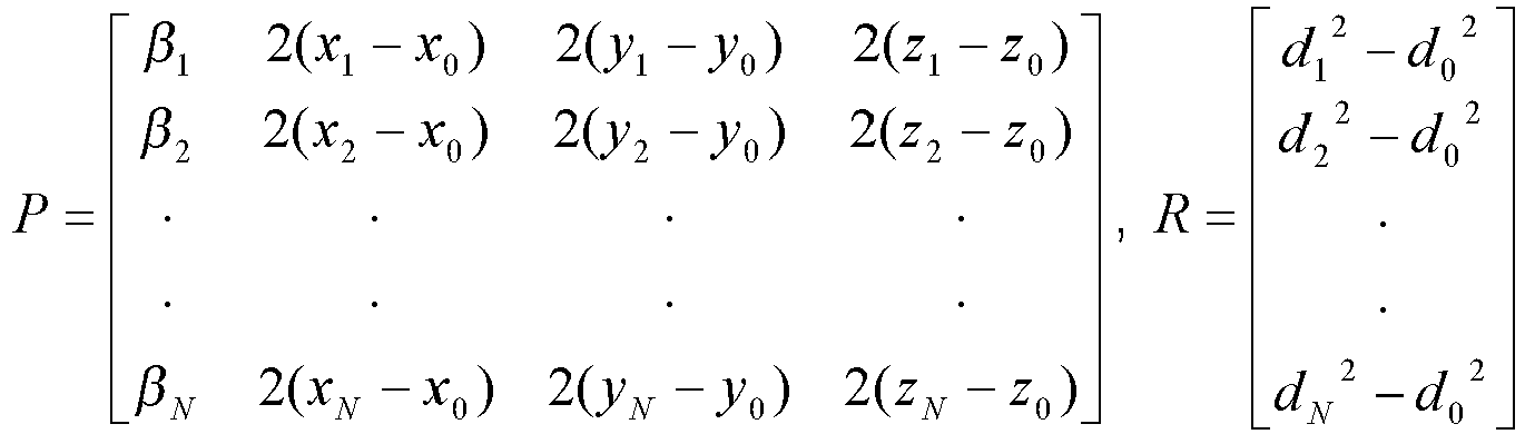
The overall equation (Equation 4) may be represented by the following matrix equation:
The terms xi, yi, zi, (for i = 0 to N) within matrix P represent the known positions or coordinates in the three-dimensional space wheremobile sensor 100 ascertains the received signal strength (RSS) measurements, while the terms r0 2, x, y, and z in the solution matrix are unknown and to be solved by the above equation (Equation 6). The determined values for x, y, and z represent the coordinates (or location) of radio frequency (RF) emitter 120 within the three-dimensional space, while the determined value for r0 2 represents the square of the distance between radio frequency (RF) emitter 120 and the known reference location (e.g., at coordinates x0, y0, and z0 within the three-dimensional space) ofmobile sensor 100.
The values for the unknown variables (e.g., r0 2, x, y, and z) indicating the location of radio frequency (RF) emitter 120 may be determined by solving for these variables inEquation 6, thereby providing the following expression:
where PT represents the transpose of matrix P, and (PTP)-1 represents the inverse of the product of matrix P and the transpose of matrix P. - In order to determine the unknown variables (e.g., r0 2, x, y, and z) indicating the location of radio frequency (RF) emitter 120 in the above equation (Equation 7), the parameter, β i , of matrix P may be estimated based on the measurements of received signal strength (RSS) obtained by
mobile sensor 100. Considering the line of sight (LOS) propagation loss between mobile sensor 100 (e.g., unmanned air vehicle (UAV)) and radio frequency (RF) emitter 120, the received signal power, pi, at the ith location alongpath 110 is inversely proportional to the square law of the distance, ri, between the mobile sensor (e.g., unmanned air vehicle (UAV)) and the radio frequency (RF) emitter. Assuming the power of radio frequency (RF) emitter 120 remains constant during the measurements of received signal strength (RSS) alongpath 110, the parameter, β i , may be estimated based on the received signal strength (RSS) or power measurements as follows:
- At least four independent equations (or at least four rows of matrices P and R) are required to determine the four unknown variables (e.g., r0 2, x, y, and z) and, hence, the location of radio frequency (RF)
emitter 120. However, measurements from at least five locations are required to provide estimates for the parameter, β i (e.g., a reference measurement for p0, and a measurement for each pi, for i = 1 to 4). - The estimates for the parameter, βi (for i = 1 to N), and the various terms that can be derived from the known measuring locations of mobile sensor 100 (e.g., xi, yi, zi (for i = 0 to N); di 2 (for i = 0 to N), etc.) are applied to matrices P and R at
step 302. The applied values within matrices P and R are utilized inEquation 7 to determine the values for the unknown variables (e.g., r0 2, x, y, and z) in the solution matrix atstep 304. Since there are path loss model errors, signal fading and/or shadowing effects, noise, interference, and implementation errors that impact the measurement, the above determination (Equations 1 - 7) is formulated to provide a Least Mean Square (LMS) solution for the variables in the solution matrix. - The determined Least Mean Square (LMS) values for x, y, and z within the solution matrix (derived from Equation 7) represent the coordinates of radio frequency (RF) emitter 120 within the three-dimensional space, and are utilized to provide the Least Mean Square (LMS) location of the radio frequency (RF) emitter within that space at
step 306. The determined location of the radio frequency (RF) emitter may be used for various applications atstep 308. For example, the location information may be processed byprocessor 230 or forwarded to another system viainterface unit 270. The location information may be processed to direct or control a vehicle or other platform to an emitter at a location of interest (e.g., to provide assistance at that location, etc.). Further, the location information may be utilized to generate an image of the area and indicate the emitter locations. - In order to assess the accuracy of the Least Mean Square (LMS) solution, an error vector, ξ, representing the error for the Least Mean Square (LMS) solution may be expressed by the following relationship:

The values for the solved variables (e.g., r0 2, x, y, and z) are utilized to determine the error vector. If a vector, Xo , provided Least Mean Square (LMS) values for the unknown variables (e.g., r0 2, x, y, and z), the Least Mean Square (LMS) error vector, ξo, may be expressed as follows:
The transpose of the P matrix must be orthogonal to the Least Mean Square (LMS) error vector, ξo, thereby providing the following expression:
Accordingly, the Least Mean Square (LMS) solution vector, Xo , must satisfy the orthogonal property, which may be expressed as follows based on the above equations (Equations 10 and 11):
Therefore, the Least Mean Square (LMS) solution vector, Xo , may expressed as follows:
Substituting the Least Mean Square (LMS) solution vector, Xo , into the error equation (Equation 10) gives the following expression for the error vector (e.g., indicating the error of the Least Mean Square (LMS) solution (e.g., values for variables r0 2, x, y, and z from Equation 7) for each of the measuring locations of mobile sensor 100):
where I is the identity matrix, (P TP)-1 PT is a projection matrix that projects the matrix R onto the column space of matrix P, and [(PTP)-1 PT-I] is a projection matrix that projects the matrix R onto the orthogonal complement of the column space of matrix P. Geometrically, the projection of the matrix R onto the orthogonal complement of the column space of matrix P assures the orthogonally between the error vector and the column space of matrix P that provides the Least Mean Square (LMS) solution. - The geolocation technique of a present invention embodiment employing small unmanned air vehicles (UAV) has been modeled and simulated using Matlab tools available from The Mathworks, Inc. of Natick, Massachusetts. A graphical illustration of the simulation results providing the relationship between geolocation error and the quantity of locations for received signal strength (RSS) measurements is illustrated in
Fig. 4 . In the simulation, the locations of an unmanned air vehicle (UAV) were randomly generated, and the following conditions were assumed: the signal to noise ratio (SNR) was 10dB; the emitter power remained constant during the measurements; the variance of Lognormal shadow varied from 0 to 5dB; and the path loss follows the line of sight (LOS) law. - As viewed in
Figure 4 , a Root Mean Square (RMS) error of the geolocation estimates (e.g., derived from the error vector of Equation 14) for a radio frequency (RF) emitter converges to a robust level with eight or more measuring locations. The geolocation estimates perform well for the variance of Lognormal shadowing less than 2dB, which is achievable with a line of sight (LOS) path loss condition offered by the unmanned air vehicle (UAV). Two samples of results of a Monte Carlo simulation conducted for various operating scenarios and randomized parameter variations are illustrated inFig. 5 . The simulations provide the geolocation characteristics for eight measuring locations (e.g.,indicators 10 as viewed inFig. 5 ) and one emitter location (e.g.,indicator 20 as viewed inFig. 5 ). The simulation was performed for 100 randomized paths with a signal to noise ratio (SNR) of 10dB, and a variance of Lognormal Shadow of 0 or 2dB. The simulation shows that the geolocation technique of present invention embodiments provides an unbiased three-dimensional geolocation estimate (e.g., where the geolocation estimates are shown byindicators 30, and the averaged estimate is shown byindicator 40 as viewed inFig. 5 ). The simulation results indicate that the present invention geolocation technique is compatible with small unmanned air vehicles (UAV), and provides geolocation estimates of radio frequency (RF) emitters with enhanced reliability. - It will be appreciated that the embodiments described above and illustrated in the drawings represent only a few of the many ways of implementing a system and method for three-dimensional geolocation of emitters based on energy or received signal strength (RSS) measurements.
- The environment of the present invention embodiments may include any quantity of mobile sensors, and emitters. The emitters may be implemented by any quantity of any conventional or other devices emitting radio frequency (RF) or any other suitable energy signals (e.g., energy signals in any suitable bands (e.g., infrared, microwave, optical, etc.)). The emitters may be located at any quantity of any desired locations within the three-dimensional space of the environment. The mobile sensors may be implemented by any quantity of any conventional or other mobile or stationary vehicle or platform (e.g., unmanned air vehicle (UAV), air vehicle, ground vehicle, platform or structure mounted at a location or on a vehicle, etc.), and may include any quantity of any conventional or other sensing device (e.g., RF or other sensor, etc.). The mobile sensors may each measure any desired characteristics of emitted signals at any one or more locations within the environment.
- The pre-planned path may traverse any desired locations within the environment, where any quantity of measurements may be obtained during traversal of the path. Further, measurements may be obtained at any locations residing within a specified offset or range from the pre-planned path. Alternatively, the path may be determined in random fashion.
The antenna may be implemented by any conventional or other antenna (e.g., omni-directional, directional, etc.) configurable to receive the signals emitted from the one or more emitters. The receiver may be implemented by any conventional or other receiving device capable of receiving the emitted radio frequency (RF) or other energy signals. The radiometer may be implemented by any conventional or other device to measure the energy or received signal strength (RSS) or other characteristics of a received signal. The radiometer may be included within or separate from the receiver. - The processor may be implemented by any quantity of any conventional or other computer systems or processing units (e.g., a microprocessor, a microcontroller, systems on a chip (SOCs), fixed or programmable logic, etc.), and may include any commercially available or custom software (e.g., communications software, location modules, etc.).
- It is to be understood that the software (e.g., location modules, etc.) for the processor of the present invention embodiments may be implemented in any desired computer language and could be developed by one of ordinary skill in the computer arts based on the functional descriptions contained in the specification and flow charts illustrated in the drawings. Further, any references herein of software performing various functions generally refer to computer systems or processors performing those functions under software control. The processor of the present invention embodiments may alternatively be implemented by any type of hardware and/or other processing circuitry. The various functions of the processor may be distributed in any manner among any quantity of software modules or units, processing or computer systems and/or circuitry, where the computer or processing systems may be disposed locally or remotely of each other and communicate via any suitable communications medium (e.g., LAN, WAN, Intranet, Internet, hardwire, modem connection, wireless, etc.). For example, the functions of the present invention embodiments may be distributed in any manner among the processor, receiver, and/or external devices. The software and/or algorithms described above and illustrated in the flow charts may be modified in any manner that accomplishes the functions described herein. In addition, the functions in the flow charts or description may be performed in any order that accomplishes a desired operation.
- The software of the present invention embodiments (e.g., location modules, etc.) may be available on a program product apparatus or device including a recordable or computer usable medium (e.g., magnetic or optical mediums, magneto-optic mediums, floppy diskettes, CD-ROM, DVD, memory devices, etc.) for use on stand-alone systems or systems connected by a network or other communications medium, and/or may be downloaded (e.g., in the form of carrier waves, packets, etc.) to systems via a network or other communications medium. Further, the tangible recordable or computer usable medium may be encoded with instructions or logic to perform the functions described herein (e.g., embedded logic such as an application specific integrated circuit (ASIC), digital signal processor (DSP) instructions, software that is executed by a processor, etc.).
- The memory may be included within or external of the processor, and may be implemented by any conventional or other memory unit with any suitable storage capacity and any type of memory (e.g., random access memory (RAM), read only memory (ROM), etc.). The memory may store any desired information for performing the geolocation technique of present invention embodiments (e.g., location modules, data, etc.). The interface unit may be implemented by any quantity of any conventional or other communications device (e.g., wireless communications device, wired communication device, etc.), and may be configured for communication over any desired network (e.g., wireless, cellular, LAN, WAN, Internet, Intranet, VPN, etc.).
- Present invention embodiments may employ any quantity of variables or equations to determine the estimated location of one or more emitters, provided that the quantity of equations is greater than or equal to the quantity of unknown variables. Further, any conventional or other techniques may be employed to produce the location estimate with minimal error (e.g., Least Mean Square (LMS), etc.). The equations may be represented in any desired form (e.g., matrix form, vectors, scalars, etc.), and be solved in any desired fashion to enable determination of the emitter location. The location estimate may be produced and/or converted to any desired form, and may be provided with respect to any desired reference (e.g., coordinates within the space, longitude and latitude indications, GPS coordinates, etc.).
- The resulting location estimate may be utilized for any suitable applications (e.g., generation of a map image of the area, vehicle or other platform guidance systems to direct the vehicle or platform toward or away from areas, radar or other detection systems, etc.).
- The various indices (e.g., i, N, etc.) are preferably integers, but may be any types of numbers with any suitable numeric ranges.
It is to be understood that the terms "top", "bottom", "front", "rear", "side", "height", "length", "width", "upper", "lower", "vertical" and the like are used herein merely to describe points of reference and do not limit the present invention to any particular orientation or configuration.
From the foregoing description, it will be appreciated that the invention makes available a novel system and method for three-dimensional geolocation of emitters based on energy or received signal strength (RSS) measurements, wherein locations of radio frequency (RF) emitters in a three-dimensional space are determined based on energy or received signal strength (RSS) measurements of the emitters at various locations. - Having described example embodiments of a new and improved system and method for three-dimensional geolocation of emitters based on energy or received signal strength (RSS) measurements, it is believed that other modifications, variations and changes will be suggested to those skilled in the art in view of the teachings set forth herein. It is therefore to be understood that all such variations, modifications and changes are believed to fall within the scope of the present invention as defined by the appended claims.
Claims (8)
- A system (200) for locating an emitter (120) within an area comprising:an unmanned air vehicle (UAV) that traverses a pre-planned path (110) through said area to obtain signal strength measurements at a plurality of locations within said area with a line of sight condition that reduces effects from signal fading and shadowing, wherein said unmanned air vehicle (UAV) includes a receiver (210) to receive signals, including radio signals, transmitted by said emitter (120) and obtain a series of measurements of signal strength for said received signals at each of said plurality of different locations within said area; anda processor (250) to process said signal strength measurements to locate said emitter (120) within said area, wherein said processor (250) includes:a location module to process said signal strength measurements and select for each location the signal strength measurement with a maximum signal to noise ratio from the series of signal strength measurements for that location, and determine a three-dimensional location of said emitter (120) within said area based on relationships of distances between said emitter (120) and each of said plurality of locations, wherein said distances are unknown, said selected signal strength measurements are proportional to said unknown distances, and said location module includes:a variable module to determine said three-dimensional location by solving a set of simultaneous equations relating to said distances, wherein said set of simultaneous equations includes a set of variables representing said unknown distances between said emitter (120) and said plurality of locations, and said unknown variables representing coordinates of said three-dimensional location of said emitter (120) within said area, and wherein said set of variables representing said unknown distances within said set of simultaneous equations includes values that are approximated by corresponding selected signal strength measurements to solve for said unknown variables and determine said three-dimensional location.
- The system of claim 1, wherein said variable module in particular solves said set of simultaneous equations using a Least Mean Square technique.
- The system of claim 1, wherein said location module includes:a parameter module to determine a parameter for said set of simultaneous equations based on said selected signal strength measurements, wherein said parameter in particular is based on a ratio of said selected signal strength measurements.
- The system of claim 1, wherein said set of simultaneous equations includes:

where

and wherein x, y, z represent said coordinates of said three-dimensional location of said emitter (120) within said area, r0 2 represents a square of a distance between said emitter (120) and a reference location, xi, yi, zi (for i = 0 to N) represent coordinates of said locations for obtaining said signal strength measurements, di 2 (for i = 0 to N) represents a square of a distance between a reference origin in said area and said locations for obtaining said signal strength measurements, pi (for i = 0 to N) represents a selected signal strength measurement at said locations, and N represents a quantity of said locations for obtaining said signal strength measurements. - A method for locating an emitter (120) within an area comprising:(a) receiving signals, including radio signals, transmitted by said emitter (120) via a receiver (210) and obtaining a series of measurements of signal strength for said received signals at each of a plurality of different locations within said area, wherein said receiver (210) is mounted on an unmanned air vehicle (UAV), and step (a) further includes:(a.1) traversing a pre-planned path (110) through said area with said unmanned air vehicle (UAV) to obtain said signal strength measurements at said plurality of locations with a line of sight condition that reduces effects from signal fading and shadowing ; and(b) processing said signal strength measurements, via a processor (250), and selecting for each location the signal strength measurement with a maximum signal to noise ratio from the series of said signal strength measurements for that location, and determining a three-dimensional location of said emitter (120) within said area based on relationships of distances between said emitter (120) and each of said plurality of locations, wherein said distances are unknown, said selected signal strength measurements are proportional to said unknown distances, and step (b) further includes:(b.1) determining said three-dimensional location by solving a set of simultaneous equations relating to said distances, wherein said set of simultaneous equations includes a set of variables representing said unknown distances between said emitter (120) and said plurality of locations, and said unknown variables representing coordinates of said three-dimensional location of said emitter (120) within said area, and wherein said set of variables representing said unknown distances within said set of simultaneous equations includes values that are approximated by corresponding selected signal strength measurements to solve for said unknown variables and determine said three-dimensional location.
- The method of claim 5, wherein step (b.1) in particular further includes:(b.1.1) solving said set of simultaneous equations using a Least Mean Square technique.
- The method of claim 5, wherein step (b) further includes:determining a parameter for said set of simultaneous equations based on said selected signal strength measurements, wherein said parameter in particular is based on a ratio of said selected signal strength measurements.
- The method of claim 5, wherein said set of simultaneous equations includes:

where

and wherein x, y, z represent said coordinates of said three-dimensional location of said emitter (120) within said area, r0 2 represents a square of a distance between said emitter (120) and a reference location, xi, yi, zi (for i = 0 to N) represent coordinates of said locations for obtaining said signal strength measurements, di 2 (for i = 0 to N) represents a square of a distance between a reference origin in said area and said locations for obtaining said signal strength measurements, pi (for i = 0 to N) represents a selected signal strength measurement at said locations, and N represents a quantity of said locations for obtaining said signal strength measurements.
Applications Claiming Priority (1)
| Application Number | Priority Date | Filing Date | Title |
|---|---|---|---|
| US13/049,443 US8878726B2 (en) | 2011-03-16 | 2011-03-16 | System and method for three-dimensional geolocation of emitters based on energy measurements |
Publications (2)
| Publication Number | Publication Date |
|---|---|
| EP2500743A1 EP2500743A1 (en) | 2012-09-19 |
| EP2500743B1 true EP2500743B1 (en) | 2016-02-24 |
Family
ID=45954315
Family Applications (1)
| Application Number | Title | Priority Date | Filing Date |
|---|---|---|---|
| EP12159186.1A Not-in-force EP2500743B1 (en) | 2011-03-16 | 2012-03-13 | System and method for three-dimensional geolocation of emitters based on energy measurements |
Country Status (3)
| Country | Link |
|---|---|
| US (1) | US8878726B2 (en) |
| EP (1) | EP2500743B1 (en) |
| IL (1) | IL218675A (en) |
Families Citing this family (177)
| Publication number | Priority date | Publication date | Assignee | Title |
|---|---|---|---|---|
| US8878725B2 (en) | 2011-05-19 | 2014-11-04 | Exelis Inc. | System and method for geolocation of multiple unknown radio frequency signal sources |
| US8615190B2 (en) | 2011-05-31 | 2013-12-24 | Exelis Inc. | System and method for allocating jamming energy based on three-dimensional geolocation of emitters |
| US8723730B2 (en) | 2011-07-27 | 2014-05-13 | Exelis Inc. | System and method for direction finding and geolocation of emitters based on line-of-bearing intersections |
| KR101984504B1 (en) * | 2012-02-29 | 2019-09-03 | 삼성전자주식회사 | System and Method for estimating 3D position and orientation accurately |
| US9113347B2 (en) | 2012-12-05 | 2015-08-18 | At&T Intellectual Property I, Lp | Backhaul link for distributed antenna system |
| US10009065B2 (en) | 2012-12-05 | 2018-06-26 | At&T Intellectual Property I, L.P. | Backhaul link for distributed antenna system |
| US9525524B2 (en) | 2013-05-31 | 2016-12-20 | At&T Intellectual Property I, L.P. | Remote distributed antenna system |
| US9999038B2 (en) | 2013-05-31 | 2018-06-12 | At&T Intellectual Property I, L.P. | Remote distributed antenna system |
| US8897697B1 (en) | 2013-11-06 | 2014-11-25 | At&T Intellectual Property I, Lp | Millimeter-wave surface-wave communications |
| US9209902B2 (en) | 2013-12-10 | 2015-12-08 | At&T Intellectual Property I, L.P. | Quasi-optical coupler |
| US20150358936A1 (en) * | 2014-06-05 | 2015-12-10 | AthenTek Incorporated | Method of estimating a position of a signal source, and server and mobile device utilizing the same |
| US9692101B2 (en) | 2014-08-26 | 2017-06-27 | At&T Intellectual Property I, L.P. | Guided wave couplers for coupling electromagnetic waves between a waveguide surface and a surface of a wire |
| US9768833B2 (en) | 2014-09-15 | 2017-09-19 | At&T Intellectual Property I, L.P. | Method and apparatus for sensing a condition in a transmission medium of electromagnetic waves |
| US10063280B2 (en) | 2014-09-17 | 2018-08-28 | At&T Intellectual Property I, L.P. | Monitoring and mitigating conditions in a communication network |
| US20160088498A1 (en) * | 2014-09-18 | 2016-03-24 | King Fahd University Of Petroleum And Minerals | Unmanned aerial vehicle for antenna radiation characterization |
| US9615269B2 (en) | 2014-10-02 | 2017-04-04 | At&T Intellectual Property I, L.P. | Method and apparatus that provides fault tolerance in a communication network |
| US9685992B2 (en) | 2014-10-03 | 2017-06-20 | At&T Intellectual Property I, L.P. | Circuit panel network and methods thereof |
| US9503189B2 (en) | 2014-10-10 | 2016-11-22 | At&T Intellectual Property I, L.P. | Method and apparatus for arranging communication sessions in a communication system |
| US9973299B2 (en) | 2014-10-14 | 2018-05-15 | At&T Intellectual Property I, L.P. | Method and apparatus for adjusting a mode of communication in a communication network |
| US9762289B2 (en) | 2014-10-14 | 2017-09-12 | At&T Intellectual Property I, L.P. | Method and apparatus for transmitting or receiving signals in a transportation system |
| US10301018B2 (en) | 2014-10-17 | 2019-05-28 | Tyco Fire & Security Gmbh | Fixed drone visualization in security systems |
| US9769020B2 (en) | 2014-10-21 | 2017-09-19 | At&T Intellectual Property I, L.P. | Method and apparatus for responding to events affecting communications in a communication network |
| US9312919B1 (en) | 2014-10-21 | 2016-04-12 | At&T Intellectual Property I, Lp | Transmission device with impairment compensation and methods for use therewith |
| US9627768B2 (en) | 2014-10-21 | 2017-04-18 | At&T Intellectual Property I, L.P. | Guided-wave transmission device with non-fundamental mode propagation and methods for use therewith |
| US9653770B2 (en) | 2014-10-21 | 2017-05-16 | At&T Intellectual Property I, L.P. | Guided wave coupler, coupling module and methods for use therewith |
| US9520945B2 (en) | 2014-10-21 | 2016-12-13 | At&T Intellectual Property I, L.P. | Apparatus for providing communication services and methods thereof |
| US9577306B2 (en) | 2014-10-21 | 2017-02-21 | At&T Intellectual Property I, L.P. | Guided-wave transmission device and methods for use therewith |
| US9780834B2 (en) | 2014-10-21 | 2017-10-03 | At&T Intellectual Property I, L.P. | Method and apparatus for transmitting electromagnetic waves |
| US10243784B2 (en) | 2014-11-20 | 2019-03-26 | At&T Intellectual Property I, L.P. | System for generating topology information and methods thereof |
| US9461706B1 (en) | 2015-07-31 | 2016-10-04 | At&T Intellectual Property I, Lp | Method and apparatus for exchanging communication signals |
| US9680670B2 (en) | 2014-11-20 | 2017-06-13 | At&T Intellectual Property I, L.P. | Transmission device with channel equalization and control and methods for use therewith |
| US10340573B2 (en) | 2016-10-26 | 2019-07-02 | At&T Intellectual Property I, L.P. | Launcher with cylindrical coupling device and methods for use therewith |
| US9997819B2 (en) | 2015-06-09 | 2018-06-12 | At&T Intellectual Property I, L.P. | Transmission medium and method for facilitating propagation of electromagnetic waves via a core |
| US9654173B2 (en) | 2014-11-20 | 2017-05-16 | At&T Intellectual Property I, L.P. | Apparatus for powering a communication device and methods thereof |
| US9954287B2 (en) | 2014-11-20 | 2018-04-24 | At&T Intellectual Property I, L.P. | Apparatus for converting wireless signals and electromagnetic waves and methods thereof |
| US9544006B2 (en) | 2014-11-20 | 2017-01-10 | At&T Intellectual Property I, L.P. | Transmission device with mode division multiplexing and methods for use therewith |
| US9800327B2 (en) | 2014-11-20 | 2017-10-24 | At&T Intellectual Property I, L.P. | Apparatus for controlling operations of a communication device and methods thereof |
| US9742462B2 (en) | 2014-12-04 | 2017-08-22 | At&T Intellectual Property I, L.P. | Transmission medium and communication interfaces and methods for use therewith |
| US10009067B2 (en) | 2014-12-04 | 2018-06-26 | At&T Intellectual Property I, L.P. | Method and apparatus for configuring a communication interface |
| US10144036B2 (en) | 2015-01-30 | 2018-12-04 | At&T Intellectual Property I, L.P. | Method and apparatus for mitigating interference affecting a propagation of electromagnetic waves guided by a transmission medium |
| US9876570B2 (en) | 2015-02-20 | 2018-01-23 | At&T Intellectual Property I, Lp | Guided-wave transmission device with non-fundamental mode propagation and methods for use therewith |
| US10089887B2 (en) | 2015-03-06 | 2018-10-02 | Timothy Just | Drone encroachment avoidance monitor |
| US10665117B2 (en) | 2015-03-06 | 2020-05-26 | Timothy Just | Drone encroachment avoidance monitor |
| US9749013B2 (en) | 2015-03-17 | 2017-08-29 | At&T Intellectual Property I, L.P. | Method and apparatus for reducing attenuation of electromagnetic waves guided by a transmission medium |
| US9705561B2 (en) | 2015-04-24 | 2017-07-11 | At&T Intellectual Property I, L.P. | Directional coupling device and methods for use therewith |
| US10224981B2 (en) | 2015-04-24 | 2019-03-05 | At&T Intellectual Property I, Lp | Passive electrical coupling device and methods for use therewith |
| US9948354B2 (en) | 2015-04-28 | 2018-04-17 | At&T Intellectual Property I, L.P. | Magnetic coupling device with reflective plate and methods for use therewith |
| US9793954B2 (en) | 2015-04-28 | 2017-10-17 | At&T Intellectual Property I, L.P. | Magnetic coupling device and methods for use therewith |
| US9871282B2 (en) | 2015-05-14 | 2018-01-16 | At&T Intellectual Property I, L.P. | At least one transmission medium having a dielectric surface that is covered at least in part by a second dielectric |
| US9748626B2 (en) | 2015-05-14 | 2017-08-29 | At&T Intellectual Property I, L.P. | Plurality of cables having different cross-sectional shapes which are bundled together to form a transmission medium |
| US9490869B1 (en) | 2015-05-14 | 2016-11-08 | At&T Intellectual Property I, L.P. | Transmission medium having multiple cores and methods for use therewith |
| US10650940B2 (en) | 2015-05-15 | 2020-05-12 | At&T Intellectual Property I, L.P. | Transmission medium having a conductive material and methods for use therewith |
| US20170329351A1 (en) * | 2015-05-22 | 2017-11-16 | Qualcomm Incorporated | Apparatus-assisted sensor data collection |
| US9917341B2 (en) | 2015-05-27 | 2018-03-13 | At&T Intellectual Property I, L.P. | Apparatus and method for launching electromagnetic waves and for modifying radial dimensions of the propagating electromagnetic waves |
| US9866309B2 (en) | 2015-06-03 | 2018-01-09 | At&T Intellectual Property I, Lp | Host node device and methods for use therewith |
| US10812174B2 (en) | 2015-06-03 | 2020-10-20 | At&T Intellectual Property I, L.P. | Client node device and methods for use therewith |
| US10103801B2 (en) | 2015-06-03 | 2018-10-16 | At&T Intellectual Property I, L.P. | Host node device and methods for use therewith |
| US9912381B2 (en) | 2015-06-03 | 2018-03-06 | At&T Intellectual Property I, Lp | Network termination and methods for use therewith |
| US9913139B2 (en) | 2015-06-09 | 2018-03-06 | At&T Intellectual Property I, L.P. | Signal fingerprinting for authentication of communicating devices |
| US10142086B2 (en) | 2015-06-11 | 2018-11-27 | At&T Intellectual Property I, L.P. | Repeater and methods for use therewith |
| US9608692B2 (en) | 2015-06-11 | 2017-03-28 | At&T Intellectual Property I, L.P. | Repeater and methods for use therewith |
| US9820146B2 (en) | 2015-06-12 | 2017-11-14 | At&T Intellectual Property I, L.P. | Method and apparatus for authentication and identity management of communicating devices |
| US9667317B2 (en) | 2015-06-15 | 2017-05-30 | At&T Intellectual Property I, L.P. | Method and apparatus for providing security using network traffic adjustments |
| US9509415B1 (en) | 2015-06-25 | 2016-11-29 | At&T Intellectual Property I, L.P. | Methods and apparatus for inducing a fundamental wave mode on a transmission medium |
| US9640850B2 (en) | 2015-06-25 | 2017-05-02 | At&T Intellectual Property I, L.P. | Methods and apparatus for inducing a non-fundamental wave mode on a transmission medium |
| US9865911B2 (en) | 2015-06-25 | 2018-01-09 | At&T Intellectual Property I, L.P. | Waveguide system for slot radiating first electromagnetic waves that are combined into a non-fundamental wave mode second electromagnetic wave on a transmission medium |
| US10148016B2 (en) | 2015-07-14 | 2018-12-04 | At&T Intellectual Property I, L.P. | Apparatus and methods for communicating utilizing an antenna array |
| US9628116B2 (en) | 2015-07-14 | 2017-04-18 | At&T Intellectual Property I, L.P. | Apparatus and methods for transmitting wireless signals |
| US9836957B2 (en) | 2015-07-14 | 2017-12-05 | At&T Intellectual Property I, L.P. | Method and apparatus for communicating with premises equipment |
| US10170840B2 (en) | 2015-07-14 | 2019-01-01 | At&T Intellectual Property I, L.P. | Apparatus and methods for sending or receiving electromagnetic signals |
| US9847566B2 (en) | 2015-07-14 | 2017-12-19 | At&T Intellectual Property I, L.P. | Method and apparatus for adjusting a field of a signal to mitigate interference |
| US10044409B2 (en) | 2015-07-14 | 2018-08-07 | At&T Intellectual Property I, L.P. | Transmission medium and methods for use therewith |
| US10033107B2 (en) | 2015-07-14 | 2018-07-24 | At&T Intellectual Property I, L.P. | Method and apparatus for coupling an antenna to a device |
| US9853342B2 (en) | 2015-07-14 | 2017-12-26 | At&T Intellectual Property I, L.P. | Dielectric transmission medium connector and methods for use therewith |
| US9722318B2 (en) | 2015-07-14 | 2017-08-01 | At&T Intellectual Property I, L.P. | Method and apparatus for coupling an antenna to a device |
| US10341142B2 (en) | 2015-07-14 | 2019-07-02 | At&T Intellectual Property I, L.P. | Apparatus and methods for generating non-interfering electromagnetic waves on an uninsulated conductor |
| US10320586B2 (en) | 2015-07-14 | 2019-06-11 | At&T Intellectual Property I, L.P. | Apparatus and methods for generating non-interfering electromagnetic waves on an insulated transmission medium |
| US10033108B2 (en) | 2015-07-14 | 2018-07-24 | At&T Intellectual Property I, L.P. | Apparatus and methods for generating an electromagnetic wave having a wave mode that mitigates interference |
| US10205655B2 (en) | 2015-07-14 | 2019-02-12 | At&T Intellectual Property I, L.P. | Apparatus and methods for communicating utilizing an antenna array and multiple communication paths |
| US9882257B2 (en) | 2015-07-14 | 2018-01-30 | At&T Intellectual Property I, L.P. | Method and apparatus for launching a wave mode that mitigates interference |
| US10090606B2 (en) | 2015-07-15 | 2018-10-02 | At&T Intellectual Property I, L.P. | Antenna system with dielectric array and methods for use therewith |
| US9793951B2 (en) | 2015-07-15 | 2017-10-17 | At&T Intellectual Property I, L.P. | Method and apparatus for launching a wave mode that mitigates interference |
| US9608740B2 (en) | 2015-07-15 | 2017-03-28 | At&T Intellectual Property I, L.P. | Method and apparatus for launching a wave mode that mitigates interference |
| US9948333B2 (en) | 2015-07-23 | 2018-04-17 | At&T Intellectual Property I, L.P. | Method and apparatus for wireless communications to mitigate interference |
| US9871283B2 (en) | 2015-07-23 | 2018-01-16 | At&T Intellectual Property I, Lp | Transmission medium having a dielectric core comprised of plural members connected by a ball and socket configuration |
| US9749053B2 (en) | 2015-07-23 | 2017-08-29 | At&T Intellectual Property I, L.P. | Node device, repeater and methods for use therewith |
| US10784670B2 (en) | 2015-07-23 | 2020-09-22 | At&T Intellectual Property I, L.P. | Antenna support for aligning an antenna |
| US9912027B2 (en) | 2015-07-23 | 2018-03-06 | At&T Intellectual Property I, L.P. | Method and apparatus for exchanging communication signals |
| US10020587B2 (en) | 2015-07-31 | 2018-07-10 | At&T Intellectual Property I, L.P. | Radial antenna and methods for use therewith |
| US9735833B2 (en) | 2015-07-31 | 2017-08-15 | At&T Intellectual Property I, L.P. | Method and apparatus for communications management in a neighborhood network |
| US9967173B2 (en) | 2015-07-31 | 2018-05-08 | At&T Intellectual Property I, L.P. | Method and apparatus for authentication and identity management of communicating devices |
| US9904535B2 (en) | 2015-09-14 | 2018-02-27 | At&T Intellectual Property I, L.P. | Method and apparatus for distributing software |
| US10009063B2 (en) | 2015-09-16 | 2018-06-26 | At&T Intellectual Property I, L.P. | Method and apparatus for use with a radio distributed antenna system having an out-of-band reference signal |
| US10136434B2 (en) | 2015-09-16 | 2018-11-20 | At&T Intellectual Property I, L.P. | Method and apparatus for use with a radio distributed antenna system having an ultra-wideband control channel |
| US10009901B2 (en) | 2015-09-16 | 2018-06-26 | At&T Intellectual Property I, L.P. | Method, apparatus, and computer-readable storage medium for managing utilization of wireless resources between base stations |
| US10079661B2 (en) | 2015-09-16 | 2018-09-18 | At&T Intellectual Property I, L.P. | Method and apparatus for use with a radio distributed antenna system having a clock reference |
| US9769128B2 (en) | 2015-09-28 | 2017-09-19 | At&T Intellectual Property I, L.P. | Method and apparatus for encryption of communications over a network |
| US9729197B2 (en) | 2015-10-01 | 2017-08-08 | At&T Intellectual Property I, L.P. | Method and apparatus for communicating network management traffic over a network |
| US9876264B2 (en) | 2015-10-02 | 2018-01-23 | At&T Intellectual Property I, Lp | Communication system, guided wave switch and methods for use therewith |
| US9882277B2 (en) | 2015-10-02 | 2018-01-30 | At&T Intellectual Property I, Lp | Communication device and antenna assembly with actuated gimbal mount |
| US10665942B2 (en) | 2015-10-16 | 2020-05-26 | At&T Intellectual Property I, L.P. | Method and apparatus for adjusting wireless communications |
| US10355367B2 (en) | 2015-10-16 | 2019-07-16 | At&T Intellectual Property I, L.P. | Antenna structure for exchanging wireless signals |
| KR20170079673A (en) * | 2015-12-30 | 2017-07-10 | 주식회사 남성 | System and method for controlling automatic flight of unmanned drones |
| EP3246723A1 (en) * | 2016-05-19 | 2017-11-22 | Sony Mobile Communications Inc | Method for setting up a positioning system |
| US10330769B1 (en) | 2016-06-06 | 2019-06-25 | The Boeing Company | Method and apparatus for geolocating emitters in a multi-emitter environment |
| WO2018011792A1 (en) * | 2016-07-12 | 2018-01-18 | Daniel Aljadeff | Methods and systems for the location and monitoring of mobile units |
| US9912419B1 (en) | 2016-08-24 | 2018-03-06 | At&T Intellectual Property I, L.P. | Method and apparatus for managing a fault in a distributed antenna system |
| US9860075B1 (en) | 2016-08-26 | 2018-01-02 | At&T Intellectual Property I, L.P. | Method and communication node for broadband distribution |
| US10291311B2 (en) | 2016-09-09 | 2019-05-14 | At&T Intellectual Property I, L.P. | Method and apparatus for mitigating a fault in a distributed antenna system |
| US11032819B2 (en) | 2016-09-15 | 2021-06-08 | At&T Intellectual Property I, L.P. | Method and apparatus for use with a radio distributed antenna system having a control channel reference signal |
| US10340600B2 (en) | 2016-10-18 | 2019-07-02 | At&T Intellectual Property I, L.P. | Apparatus and methods for launching guided waves via plural waveguide systems |
| US10135146B2 (en) | 2016-10-18 | 2018-11-20 | At&T Intellectual Property I, L.P. | Apparatus and methods for launching guided waves via circuits |
| US10135147B2 (en) | 2016-10-18 | 2018-11-20 | At&T Intellectual Property I, L.P. | Apparatus and methods for launching guided waves via an antenna |
| US10374316B2 (en) | 2016-10-21 | 2019-08-06 | At&T Intellectual Property I, L.P. | System and dielectric antenna with non-uniform dielectric |
| US9876605B1 (en) | 2016-10-21 | 2018-01-23 | At&T Intellectual Property I, L.P. | Launcher and coupling system to support desired guided wave mode |
| US10811767B2 (en) | 2016-10-21 | 2020-10-20 | At&T Intellectual Property I, L.P. | System and dielectric antenna with convex dielectric radome |
| US9991580B2 (en) | 2016-10-21 | 2018-06-05 | At&T Intellectual Property I, L.P. | Launcher and coupling system for guided wave mode cancellation |
| US10312567B2 (en) | 2016-10-26 | 2019-06-04 | At&T Intellectual Property I, L.P. | Launcher with planar strip antenna and methods for use therewith |
| US10225025B2 (en) | 2016-11-03 | 2019-03-05 | At&T Intellectual Property I, L.P. | Method and apparatus for detecting a fault in a communication system |
| US10291334B2 (en) | 2016-11-03 | 2019-05-14 | At&T Intellectual Property I, L.P. | System for detecting a fault in a communication system |
| US10224634B2 (en) | 2016-11-03 | 2019-03-05 | At&T Intellectual Property I, L.P. | Methods and apparatus for adjusting an operational characteristic of an antenna |
| US10498044B2 (en) | 2016-11-03 | 2019-12-03 | At&T Intellectual Property I, L.P. | Apparatus for configuring a surface of an antenna |
| US10090594B2 (en) | 2016-11-23 | 2018-10-02 | At&T Intellectual Property I, L.P. | Antenna system having structural configurations for assembly |
| US10340601B2 (en) | 2016-11-23 | 2019-07-02 | At&T Intellectual Property I, L.P. | Multi-antenna system and methods for use therewith |
| US10535928B2 (en) | 2016-11-23 | 2020-01-14 | At&T Intellectual Property I, L.P. | Antenna system and methods for use therewith |
| US10340603B2 (en) | 2016-11-23 | 2019-07-02 | At&T Intellectual Property I, L.P. | Antenna system having shielded structural configurations for assembly |
| US10178445B2 (en) | 2016-11-23 | 2019-01-08 | At&T Intellectual Property I, L.P. | Methods, devices, and systems for load balancing between a plurality of waveguides |
| US10305190B2 (en) | 2016-12-01 | 2019-05-28 | At&T Intellectual Property I, L.P. | Reflecting dielectric antenna system and methods for use therewith |
| US10361489B2 (en) | 2016-12-01 | 2019-07-23 | At&T Intellectual Property I, L.P. | Dielectric dish antenna system and methods for use therewith |
| US10020844B2 (en) | 2016-12-06 | 2018-07-10 | T&T Intellectual Property I, L.P. | Method and apparatus for broadcast communication via guided waves |
| US10727599B2 (en) | 2016-12-06 | 2020-07-28 | At&T Intellectual Property I, L.P. | Launcher with slot antenna and methods for use therewith |
| US9927517B1 (en) | 2016-12-06 | 2018-03-27 | At&T Intellectual Property I, L.P. | Apparatus and methods for sensing rainfall |
| US10326494B2 (en) | 2016-12-06 | 2019-06-18 | At&T Intellectual Property I, L.P. | Apparatus for measurement de-embedding and methods for use therewith |
| US10819035B2 (en) | 2016-12-06 | 2020-10-27 | At&T Intellectual Property I, L.P. | Launcher with helical antenna and methods for use therewith |
| US10694379B2 (en) | 2016-12-06 | 2020-06-23 | At&T Intellectual Property I, L.P. | Waveguide system with device-based authentication and methods for use therewith |
| US10439675B2 (en) | 2016-12-06 | 2019-10-08 | At&T Intellectual Property I, L.P. | Method and apparatus for repeating guided wave communication signals |
| US10755542B2 (en) | 2016-12-06 | 2020-08-25 | At&T Intellectual Property I, L.P. | Method and apparatus for surveillance via guided wave communication |
| US10637149B2 (en) | 2016-12-06 | 2020-04-28 | At&T Intellectual Property I, L.P. | Injection molded dielectric antenna and methods for use therewith |
| US10135145B2 (en) | 2016-12-06 | 2018-11-20 | At&T Intellectual Property I, L.P. | Apparatus and methods for generating an electromagnetic wave along a transmission medium |
| US10382976B2 (en) | 2016-12-06 | 2019-08-13 | At&T Intellectual Property I, L.P. | Method and apparatus for managing wireless communications based on communication paths and network device positions |
| US10359749B2 (en) | 2016-12-07 | 2019-07-23 | At&T Intellectual Property I, L.P. | Method and apparatus for utilities management via guided wave communication |
| US10389029B2 (en) | 2016-12-07 | 2019-08-20 | At&T Intellectual Property I, L.P. | Multi-feed dielectric antenna system with core selection and methods for use therewith |
| US10547348B2 (en) | 2016-12-07 | 2020-01-28 | At&T Intellectual Property I, L.P. | Method and apparatus for switching transmission mediums in a communication system |
| US10243270B2 (en) | 2016-12-07 | 2019-03-26 | At&T Intellectual Property I, L.P. | Beam adaptive multi-feed dielectric antenna system and methods for use therewith |
| US10168695B2 (en) | 2016-12-07 | 2019-01-01 | At&T Intellectual Property I, L.P. | Method and apparatus for controlling an unmanned aircraft |
| US10446936B2 (en) | 2016-12-07 | 2019-10-15 | At&T Intellectual Property I, L.P. | Multi-feed dielectric antenna system and methods for use therewith |
| US10139820B2 (en) | 2016-12-07 | 2018-11-27 | At&T Intellectual Property I, L.P. | Method and apparatus for deploying equipment of a communication system |
| US10027397B2 (en) | 2016-12-07 | 2018-07-17 | At&T Intellectual Property I, L.P. | Distributed antenna system and methods for use therewith |
| US9893795B1 (en) | 2016-12-07 | 2018-02-13 | At&T Intellectual Property I, Lp | Method and repeater for broadband distribution |
| US10264467B2 (en) | 2016-12-08 | 2019-04-16 | At&T Intellectual Property I, L.P. | Method and apparatus for collecting data associated with wireless communications |
| US10411356B2 (en) | 2016-12-08 | 2019-09-10 | At&T Intellectual Property I, L.P. | Apparatus and methods for selectively targeting communication devices with an antenna array |
| US10530505B2 (en) | 2016-12-08 | 2020-01-07 | At&T Intellectual Property I, L.P. | Apparatus and methods for launching electromagnetic waves along a transmission medium |
| US10777873B2 (en) | 2016-12-08 | 2020-09-15 | At&T Intellectual Property I, L.P. | Method and apparatus for mounting network devices |
| US10601494B2 (en) | 2016-12-08 | 2020-03-24 | At&T Intellectual Property I, L.P. | Dual-band communication device and method for use therewith |
| US10326689B2 (en) | 2016-12-08 | 2019-06-18 | At&T Intellectual Property I, L.P. | Method and system for providing alternative communication paths |
| US10938108B2 (en) | 2016-12-08 | 2021-03-02 | At&T Intellectual Property I, L.P. | Frequency selective multi-feed dielectric antenna system and methods for use therewith |
| US9911020B1 (en) | 2016-12-08 | 2018-03-06 | At&T Intellectual Property I, L.P. | Method and apparatus for tracking via a radio frequency identification device |
| US10389037B2 (en) | 2016-12-08 | 2019-08-20 | At&T Intellectual Property I, L.P. | Apparatus and methods for selecting sections of an antenna array and use therewith |
| US9998870B1 (en) | 2016-12-08 | 2018-06-12 | At&T Intellectual Property I, L.P. | Method and apparatus for proximity sensing |
| US10069535B2 (en) | 2016-12-08 | 2018-09-04 | At&T Intellectual Property I, L.P. | Apparatus and methods for launching electromagnetic waves having a certain electric field structure |
| US10103422B2 (en) | 2016-12-08 | 2018-10-16 | At&T Intellectual Property I, L.P. | Method and apparatus for mounting network devices |
| US10916969B2 (en) | 2016-12-08 | 2021-02-09 | At&T Intellectual Property I, L.P. | Method and apparatus for providing power using an inductive coupling |
| US10340983B2 (en) | 2016-12-09 | 2019-07-02 | At&T Intellectual Property I, L.P. | Method and apparatus for surveying remote sites via guided wave communications |
| US10264586B2 (en) | 2016-12-09 | 2019-04-16 | At&T Mobility Ii Llc | Cloud-based packet controller and methods for use therewith |
| US9838896B1 (en) | 2016-12-09 | 2017-12-05 | At&T Intellectual Property I, L.P. | Method and apparatus for assessing network coverage |
| US9973940B1 (en) | 2017-02-27 | 2018-05-15 | At&T Intellectual Property I, L.P. | Apparatus and methods for dynamic impedance matching of a guided wave launcher |
| US10298293B2 (en) | 2017-03-13 | 2019-05-21 | At&T Intellectual Property I, L.P. | Apparatus of communication utilizing wireless network devices |
| EP3603225B1 (en) * | 2017-03-23 | 2022-07-27 | Interdigital Patent Holdings, Inc. | Method and system for altitude path-loss based power control for aerial vehicles |
| TWI650973B (en) * | 2017-03-30 | 2019-02-11 | 財團法人電信技術中心 | Wireless communication based method for collecting data |
| US10823842B2 (en) | 2017-08-06 | 2020-11-03 | Regulus Cyber Ltd. | System and method for generating a temporal map of radio frequency (RF) signals |
| FR3072180B1 (en) | 2017-10-06 | 2019-11-01 | Commissariat A L'energie Atomique Et Aux Energies Alternatives | METHOD FOR LOCATING A TERMINAL OF ACCESS TO A COMMUNICATION NETWORK |
| US11054843B2 (en) * | 2018-03-12 | 2021-07-06 | Nec Corporation | Self-configuring long term evolution radio access network on unmanned autonomous vehicles |
| CN115372889A (en) * | 2018-06-29 | 2022-11-22 | 海丰通航科技有限公司 | Method for over-the-air radio monitoring |
| TWI718450B (en) | 2018-12-10 | 2021-02-11 | 財團法人工業技術研究院 | A method and system of measuring radio wave distribution of a radio signal source and estimating corresponding radio characteristics by using a flying vehicle |
| US20240118372A1 (en) * | 2022-07-28 | 2024-04-11 | The United States Of America, As Represented By The Secretary Of The Navy | Methods and apparatus for ascertaining locations of unknown radio frequency emitters using software defined radio (sdr) amplitude measurements |
| CN116582140A (en) * | 2023-05-26 | 2023-08-11 | 泰斗微电子科技有限公司 | Signal transmitting method, device, antenna and storage medium |
| CN117156394B (en) * | 2023-11-01 | 2024-02-02 | 航天晨光股份有限公司 | Tank car remote positioning monitoring system and method |
Family Cites Families (43)
| Publication number | Priority date | Publication date | Assignee | Title |
|---|---|---|---|---|
| IT8448723A0 (en) | 1983-08-13 | 1984-02-13 | British Aerospace | IF IN CORRESPONDENCE TO A SERIES SYSTEM FOR ALLOCATION OF RESOURCES REQUESTS AND METHOD FOR DETERMINING THE OPTIMAL DISTRIBUTION OF RESOURCES |
| US5055851A (en) * | 1988-05-16 | 1991-10-08 | Trackmobile, Inc. | Vehicle location system |
| US5767804A (en) | 1995-06-15 | 1998-06-16 | Trimble Navigation Limited | Integrated radio direction finding and GPS receiver tracking system |
| AU708274B2 (en) * | 1995-09-20 | 1999-07-29 | Kratos Integral Holdings, Llc | Locating the source of an unknown signal |
| US5883598A (en) * | 1995-12-15 | 1999-03-16 | Signatron Technology Corporation | Position location system and method |
| US5987329A (en) | 1997-07-30 | 1999-11-16 | Ericsson Inc | System and method for mobile telephone location measurement using a hybrid technique |
| US6414634B1 (en) * | 1997-12-04 | 2002-07-02 | Lucent Technologies Inc. | Detecting the geographical location of wireless units |
| US6141558A (en) | 1998-05-07 | 2000-10-31 | Motorola, Inc. | Method and apparatus for locating a subscriber unit in a communication system |
| US6453168B1 (en) * | 1999-08-02 | 2002-09-17 | Itt Manufacturing Enterprises, Inc | Method and apparatus for determining the position of a mobile communication device using low accuracy clocks |
| GB0203621D0 (en) | 2002-02-15 | 2002-04-03 | Bae Systems Defence Sysytems L | Emitter location system |
| US6711528B2 (en) | 2002-04-22 | 2004-03-23 | Harris Corporation | Blind source separation utilizing a spatial fourth order cumulant matrix pencil |
| US7623871B2 (en) * | 2002-04-24 | 2009-11-24 | Qualcomm Incorporated | Position determination for a wireless terminal in a hybrid position determination system |
| US6865490B2 (en) | 2002-05-06 | 2005-03-08 | The Johns Hopkins University | Method for gradient flow source localization and signal separation |
| US7711375B2 (en) | 2002-08-06 | 2010-05-04 | Hang Liu | Method and system for determining a location of a wireless transmitting device and guiding the search for the same |
| US7102508B2 (en) | 2002-09-09 | 2006-09-05 | Persephone, Inc. | Method and apparatus for locating and tracking persons |
| US7071791B1 (en) | 2003-01-30 | 2006-07-04 | The United States Of America As Represented By The Secretary Of The Army | Automatic antenna-switching apparatus and system |
| US6910657B2 (en) | 2003-05-30 | 2005-06-28 | Raytheon Company | System and method for locating a target and guiding a vehicle toward the target |
| US7313403B2 (en) | 2003-08-06 | 2007-12-25 | Hong Kong Applied Science And Technology Research Institute Co., Ltd. | Location positioning in wireless networks |
| FR2865281B3 (en) | 2003-11-07 | 2006-01-06 | Thales Sa | METHOD FOR LOCATING ONE OR MORE TRANSMITTERS |
| FR2868541B1 (en) | 2004-03-30 | 2006-05-26 | Thales Sa | METHOD FOR BROADBAND BLIND LOCATION OF ONE OR MORE TRANSMITTERS FROM A DEFINING BEARER |
| JP2006023267A (en) * | 2004-06-09 | 2006-01-26 | Ntt Docomo Inc | Position measuring apparatus and position measuring method using multipath delay component |
| US7142108B2 (en) | 2004-08-19 | 2006-11-28 | Cognio, Inc. | System and method for monitoring and enforcing a restricted wireless zone |
| US7292189B2 (en) * | 2004-09-10 | 2007-11-06 | Worcester Polytechnic Institute | Methods and apparatus for high resolution positioning |
| US20060128311A1 (en) | 2004-12-13 | 2006-06-15 | Yohannes Tesfai | Matching receive signal strenth data associated with radio emission sources for positioning applications |
| US7257412B2 (en) | 2005-04-25 | 2007-08-14 | Mediatek Inc. | Methods and systems for location estimation |
| US7817967B2 (en) | 2005-06-21 | 2010-10-19 | Atc Technologies, Llc | Communications systems including adaptive antenna systems and methods for inter-system and intra-system interference reduction |
| DE102005048269B4 (en) * | 2005-10-08 | 2008-01-31 | Diehl Stiftung & Co. Kg | Sensor network and procedures for monitoring a terrain |
| US7233284B2 (en) | 2005-11-22 | 2007-06-19 | The United States Of America As Represented By The Secretary Of The Navy | Handheld GPS jammer locator |
| IL172267A0 (en) | 2005-11-30 | 2006-04-10 | Elta Systems Ltd | A method and system for locating an unknown emitter |
| US7498986B2 (en) | 2005-12-05 | 2009-03-03 | Honeywell International Inc. | Methods and systems for locating actuators for improvised explosive devices |
| US7551139B1 (en) | 2006-05-12 | 2009-06-23 | Northrop Grumman Corporation | Multi-platform precision passive location of continuous wave emitters |
| US7616155B2 (en) | 2006-12-27 | 2009-11-10 | Bull Jeffrey F | Portable, iterative geolocation of RF emitters |
| US7453400B2 (en) | 2007-02-02 | 2008-11-18 | Bae Systems Information And Electronic Systems Integration Inc. | Multiplatform TDOA correlation interferometer geolocation |
| WO2009084877A1 (en) | 2007-12-28 | 2009-07-09 | Samsung Electronics Co., Ltd. | Method and apparatus for transmitting/receiving downlink data in wireless communication network |
| US8290551B2 (en) | 2008-08-06 | 2012-10-16 | Direct Beam Inc. | Systems and methods for efficiently positioning a directional antenna module to receive and transmit the most effective band width of wireless transmissions |
| US20100106745A1 (en) * | 2008-10-23 | 2010-04-29 | Electronics And Telecommunications Research Institute | Method and apparatus for generating fingerprint database for wireless location |
| US8085199B2 (en) | 2008-12-13 | 2011-12-27 | Broadcom Corporation | Receiver including a matrix module to determine angular position |
| US7978139B2 (en) | 2009-06-18 | 2011-07-12 | Bae Systems Information And Electronic Systems Integration Inc. | Direction finding and geolocation of wireless devices |
| US8519889B2 (en) | 2009-07-21 | 2013-08-27 | Research In Motion Limited | Method and apparatus for estimating location of a wireless station using multi-beam transmission |
| US20110199916A1 (en) | 2010-02-12 | 2011-08-18 | David Garrett | Method and system for determining the location of a wireless access point using single device based power measurements |
| US8878725B2 (en) | 2011-05-19 | 2014-11-04 | Exelis Inc. | System and method for geolocation of multiple unknown radio frequency signal sources |
| US8615190B2 (en) | 2011-05-31 | 2013-12-24 | Exelis Inc. | System and method for allocating jamming energy based on three-dimensional geolocation of emitters |
| US8723730B2 (en) | 2011-07-27 | 2014-05-13 | Exelis Inc. | System and method for direction finding and geolocation of emitters based on line-of-bearing intersections |
-
2011
- 2011-03-16 US US13/049,443 patent/US8878726B2/en active Active
-
2012
- 2012-03-13 EP EP12159186.1A patent/EP2500743B1/en not_active Not-in-force
- 2012-03-15 IL IL218675A patent/IL218675A/en active IP Right Grant
Also Published As
| Publication number | Publication date |
|---|---|
| US20120235864A1 (en) | 2012-09-20 |
| EP2500743A1 (en) | 2012-09-19 |
| IL218675A0 (en) | 2012-07-31 |
| IL218675A (en) | 2016-06-30 |
| US8878726B2 (en) | 2014-11-04 |
Similar Documents
| Publication | Publication Date | Title |
|---|---|---|
| US8878726B2 (en) | System and method for three-dimensional geolocation of emitters based on energy measurements | |
| US8878725B2 (en) | System and method for geolocation of multiple unknown radio frequency signal sources | |
| US8615190B2 (en) | System and method for allocating jamming energy based on three-dimensional geolocation of emitters | |
| US8723730B2 (en) | System and method for direction finding and geolocation of emitters based on line-of-bearing intersections | |
| EP1862814B1 (en) | Method for selecting a positioning mode of a mobil terminal in a cellular system | |
| KR102235544B1 (en) | Channel delay determination method, positioning method, and related apparatus | |
| EP2600165B1 (en) | Wireless position determination using adjusted round trip time measurements | |
| EP1445970B1 (en) | A method and system for locating a mobile radio receiver in a radio system with multiple tranmitters | |
| US7187327B2 (en) | Method and system for determining the position of an object | |
| EP2517041B1 (en) | Locating electromagnetic signal sources | |
| KR101325579B1 (en) | Apparatus and method for estimating an orientation of a mobile terminal device | |
| Plets et al. | Experimental performance evaluation of outdoor tdoa and rss positioning in a public lora network | |
| US20090196267A1 (en) | Systems and methods for providing location based services (lbs) utilizing wlan and/or gps signals for seamless indoor and outdoor tracking | |
| KR101709411B1 (en) | Method for positioning based on weighted triangulation and method for indoor positioning using the same | |
| US12055651B2 (en) | Method and system for geolocating an object using a mobile base station | |
| US10349214B2 (en) | Localization using access point | |
| KR20160126999A (en) | Single platform Doppler geolocation | |
| EP3528003A1 (en) | System and method estimating orientation from radio measurements | |
| JP5360038B2 (en) | Radio wave monitoring apparatus and radio wave monitoring method | |
| US7362270B2 (en) | System and method to perform network node localization training using a mobile node | |
| US10547964B2 (en) | Method and device for estimating accuracy of a position determination | |
| Moro et al. | Experimental UAV-aided RSSI localization of a ground RF emitter in 865 MHz and 2.4 GHz bands | |
| US7817092B1 (en) | Agile electromagnetic geolocation | |
| EP3259609B1 (en) | Providing an indication of a heading of a mobile device | |
| EP4314865B1 (en) | Crowd sourced beacon altitudes for 3d positioning |
Legal Events
| Date | Code | Title | Description |
|---|---|---|---|
| PUAI | Public reference made under article 153(3) epc to a published international application that has entered the european phase |
Free format text: ORIGINAL CODE: 0009012 |
|
| AK | Designated contracting states |
Kind code of ref document: A1 Designated state(s): AL AT BE BG CH CY CZ DE DK EE ES FI FR GB GR HR HU IE IS IT LI LT LU LV MC MK MT NL NO PL PT RO RS SE SI SK SM TR |
|
| AX | Request for extension of the european patent |
Extension state: BA ME |
|
| 17P | Request for examination filed |
Effective date: 20130219 |
|
| GRAP | Despatch of communication of intention to grant a patent |
Free format text: ORIGINAL CODE: EPIDOSNIGR1 |
|
| INTG | Intention to grant announced |
Effective date: 20150730 |
|
| RAP1 | Party data changed (applicant data changed or rights of an application transferred) |
Owner name: EXELIS INC. |
|
| GRAS | Grant fee paid |
Free format text: ORIGINAL CODE: EPIDOSNIGR3 |
|
| INTG | Intention to grant announced |
Effective date: 20151210 |
|
| GRAA | (expected) grant |
Free format text: ORIGINAL CODE: 0009210 |
|
| AK | Designated contracting states |
Kind code of ref document: B1 Designated state(s): AL AT BE BG CH CY CZ DE DK EE ES FI FR GB GR HR HU IE IS IT LI LT LU LV MC MK MT NL NO PL PT RO RS SE SI SK SM TR |
|
| REG | Reference to a national code |
Ref country code: GB Ref legal event code: FG4D |
|
| REG | Reference to a national code |
Ref country code: CH Ref legal event code: EP Ref country code: CH Ref legal event code: NV Representative=s name: TROESCH SCHEIDEGGER WERNER AG, CH |
|
| REG | Reference to a national code |
Ref country code: AT Ref legal event code: REF Ref document number: 777005 Country of ref document: AT Kind code of ref document: T Effective date: 20160315 |
|
| REG | Reference to a national code |
Ref country code: IE Ref legal event code: FG4D |
|
| REG | Reference to a national code |
Ref country code: FR Ref legal event code: PLFP Year of fee payment: 5 |
|
| REG | Reference to a national code |
Ref country code: DE Ref legal event code: R096 Ref document number: 602012014830 Country of ref document: DE |
|
| PGFP | Annual fee paid to national office [announced via postgrant information from national office to epo] |
Ref country code: CH Payment date: 20160328 Year of fee payment: 5 |
|
| REG | Reference to a national code |
Ref country code: SE Ref legal event code: TRGR |
|
| PGFP | Annual fee paid to national office [announced via postgrant information from national office to epo] |
Ref country code: FR Payment date: 20160328 Year of fee payment: 5 |
|
| REG | Reference to a national code |
Ref country code: LT Ref legal event code: MG4D |
|
| REG | Reference to a national code |
Ref country code: NL Ref legal event code: MP Effective date: 20160224 |
|
| PG25 | Lapsed in a contracting state [announced via postgrant information from national office to epo] |
Ref country code: ES Free format text: LAPSE BECAUSE OF FAILURE TO SUBMIT A TRANSLATION OF THE DESCRIPTION OR TO PAY THE FEE WITHIN THE PRESCRIBED TIME-LIMIT Effective date: 20160224 Ref country code: HR Free format text: LAPSE BECAUSE OF FAILURE TO SUBMIT A TRANSLATION OF THE DESCRIPTION OR TO PAY THE FEE WITHIN THE PRESCRIBED TIME-LIMIT Effective date: 20160224 Ref country code: NO Free format text: LAPSE BECAUSE OF FAILURE TO SUBMIT A TRANSLATION OF THE DESCRIPTION OR TO PAY THE FEE WITHIN THE PRESCRIBED TIME-LIMIT Effective date: 20160524 Ref country code: GR Free format text: LAPSE BECAUSE OF FAILURE TO SUBMIT A TRANSLATION OF THE DESCRIPTION OR TO PAY THE FEE WITHIN THE PRESCRIBED TIME-LIMIT Effective date: 20160525 Ref country code: FI Free format text: LAPSE BECAUSE OF FAILURE TO SUBMIT A TRANSLATION OF THE DESCRIPTION OR TO PAY THE FEE WITHIN THE PRESCRIBED TIME-LIMIT Effective date: 20160224 |
|
| PGFP | Annual fee paid to national office [announced via postgrant information from national office to epo] |
Ref country code: DE Payment date: 20160331 Year of fee payment: 5 |
|
| PG25 | Lapsed in a contracting state [announced via postgrant information from national office to epo] |
Ref country code: BE Free format text: LAPSE BECAUSE OF NON-PAYMENT OF DUE FEES Effective date: 20160331 Ref country code: RS Free format text: LAPSE BECAUSE OF FAILURE TO SUBMIT A TRANSLATION OF THE DESCRIPTION OR TO PAY THE FEE WITHIN THE PRESCRIBED TIME-LIMIT Effective date: 20160224 Ref country code: PT Free format text: LAPSE BECAUSE OF FAILURE TO SUBMIT A TRANSLATION OF THE DESCRIPTION OR TO PAY THE FEE WITHIN THE PRESCRIBED TIME-LIMIT Effective date: 20160624 Ref country code: LV Free format text: LAPSE BECAUSE OF FAILURE TO SUBMIT A TRANSLATION OF THE DESCRIPTION OR TO PAY THE FEE WITHIN THE PRESCRIBED TIME-LIMIT Effective date: 20160224 Ref country code: LT Free format text: LAPSE BECAUSE OF FAILURE TO SUBMIT A TRANSLATION OF THE DESCRIPTION OR TO PAY THE FEE WITHIN THE PRESCRIBED TIME-LIMIT Effective date: 20160224 Ref country code: NL Free format text: LAPSE BECAUSE OF FAILURE TO SUBMIT A TRANSLATION OF THE DESCRIPTION OR TO PAY THE FEE WITHIN THE PRESCRIBED TIME-LIMIT Effective date: 20160224 Ref country code: PL Free format text: LAPSE BECAUSE OF FAILURE TO SUBMIT A TRANSLATION OF THE DESCRIPTION OR TO PAY THE FEE WITHIN THE PRESCRIBED TIME-LIMIT Effective date: 20160224 |
|
| PGFP | Annual fee paid to national office [announced via postgrant information from national office to epo] |
Ref country code: IT Payment date: 20160527 Year of fee payment: 5 |
|
| PG25 | Lapsed in a contracting state [announced via postgrant information from national office to epo] |
Ref country code: DK Free format text: LAPSE BECAUSE OF FAILURE TO SUBMIT A TRANSLATION OF THE DESCRIPTION OR TO PAY THE FEE WITHIN THE PRESCRIBED TIME-LIMIT Effective date: 20160224 Ref country code: EE Free format text: LAPSE BECAUSE OF FAILURE TO SUBMIT A TRANSLATION OF THE DESCRIPTION OR TO PAY THE FEE WITHIN THE PRESCRIBED TIME-LIMIT Effective date: 20160224 |
|
| REG | Reference to a national code |
Ref country code: DE Ref legal event code: R097 Ref document number: 602012014830 Country of ref document: DE |
|
| PG25 | Lapsed in a contracting state [announced via postgrant information from national office to epo] |
Ref country code: SK Free format text: LAPSE BECAUSE OF FAILURE TO SUBMIT A TRANSLATION OF THE DESCRIPTION OR TO PAY THE FEE WITHIN THE PRESCRIBED TIME-LIMIT Effective date: 20160224 Ref country code: SM Free format text: LAPSE BECAUSE OF FAILURE TO SUBMIT A TRANSLATION OF THE DESCRIPTION OR TO PAY THE FEE WITHIN THE PRESCRIBED TIME-LIMIT Effective date: 20160224 Ref country code: CZ Free format text: LAPSE BECAUSE OF FAILURE TO SUBMIT A TRANSLATION OF THE DESCRIPTION OR TO PAY THE FEE WITHIN THE PRESCRIBED TIME-LIMIT Effective date: 20160224 Ref country code: RO Free format text: LAPSE BECAUSE OF FAILURE TO SUBMIT A TRANSLATION OF THE DESCRIPTION OR TO PAY THE FEE WITHIN THE PRESCRIBED TIME-LIMIT Effective date: 20160224 |
|
| REG | Reference to a national code |
Ref country code: IE Ref legal event code: MM4A |
|
| PG25 | Lapsed in a contracting state [announced via postgrant information from national office to epo] |
Ref country code: BE Free format text: LAPSE BECAUSE OF FAILURE TO SUBMIT A TRANSLATION OF THE DESCRIPTION OR TO PAY THE FEE WITHIN THE PRESCRIBED TIME-LIMIT Effective date: 20160224 |
|
| PLBE | No opposition filed within time limit |
Free format text: ORIGINAL CODE: 0009261 |
|
| STAA | Information on the status of an ep patent application or granted ep patent |
Free format text: STATUS: NO OPPOSITION FILED WITHIN TIME LIMIT |
|
| PG25 | Lapsed in a contracting state [announced via postgrant information from national office to epo] |
Ref country code: IE Free format text: LAPSE BECAUSE OF NON-PAYMENT OF DUE FEES Effective date: 20160313 |
|
| 26N | No opposition filed |
Effective date: 20161125 |
|
| PG25 | Lapsed in a contracting state [announced via postgrant information from national office to epo] |
Ref country code: BG Free format text: LAPSE BECAUSE OF FAILURE TO SUBMIT A TRANSLATION OF THE DESCRIPTION OR TO PAY THE FEE WITHIN THE PRESCRIBED TIME-LIMIT Effective date: 20160524 Ref country code: SI Free format text: LAPSE BECAUSE OF FAILURE TO SUBMIT A TRANSLATION OF THE DESCRIPTION OR TO PAY THE FEE WITHIN THE PRESCRIBED TIME-LIMIT Effective date: 20160224 |
|
| PGFP | Annual fee paid to national office [announced via postgrant information from national office to epo] |
Ref country code: SE Payment date: 20160325 Year of fee payment: 5 |
|
| PG25 | Lapsed in a contracting state [announced via postgrant information from national office to epo] |
Ref country code: MT Free format text: LAPSE BECAUSE OF FAILURE TO SUBMIT A TRANSLATION OF THE DESCRIPTION OR TO PAY THE FEE WITHIN THE PRESCRIBED TIME-LIMIT Effective date: 20160224 |
|
| REG | Reference to a national code |
Ref country code: DE Ref legal event code: R119 Ref document number: 602012014830 Country of ref document: DE |
|
| REG | Reference to a national code |
Ref country code: SE Ref legal event code: EUG Ref country code: CH Ref legal event code: PL |
|
| PG25 | Lapsed in a contracting state [announced via postgrant information from national office to epo] |
Ref country code: SE Free format text: LAPSE BECAUSE OF NON-PAYMENT OF DUE FEES Effective date: 20170314 |
|
| REG | Reference to a national code |
Ref country code: FR Ref legal event code: ST Effective date: 20171130 |
|
| PG25 | Lapsed in a contracting state [announced via postgrant information from national office to epo] |
Ref country code: DE Free format text: LAPSE BECAUSE OF NON-PAYMENT OF DUE FEES Effective date: 20171003 Ref country code: FR Free format text: LAPSE BECAUSE OF NON-PAYMENT OF DUE FEES Effective date: 20170331 |
|
| PG25 | Lapsed in a contracting state [announced via postgrant information from national office to epo] |
Ref country code: IT Free format text: LAPSE BECAUSE OF NON-PAYMENT OF DUE FEES Effective date: 20170313 Ref country code: CH Free format text: LAPSE BECAUSE OF NON-PAYMENT OF DUE FEES Effective date: 20170331 Ref country code: LI Free format text: LAPSE BECAUSE OF NON-PAYMENT OF DUE FEES Effective date: 20170331 |
|
| REG | Reference to a national code |
Ref country code: AT Ref legal event code: MM01 Ref document number: 777005 Country of ref document: AT Kind code of ref document: T Effective date: 20170313 |
|
| PG25 | Lapsed in a contracting state [announced via postgrant information from national office to epo] |
Ref country code: CY Free format text: LAPSE BECAUSE OF FAILURE TO SUBMIT A TRANSLATION OF THE DESCRIPTION OR TO PAY THE FEE WITHIN THE PRESCRIBED TIME-LIMIT Effective date: 20160224 Ref country code: HU Free format text: LAPSE BECAUSE OF FAILURE TO SUBMIT A TRANSLATION OF THE DESCRIPTION OR TO PAY THE FEE WITHIN THE PRESCRIBED TIME-LIMIT; INVALID AB INITIO Effective date: 20120313 |
|
| PG25 | Lapsed in a contracting state [announced via postgrant information from national office to epo] |
Ref country code: MC Free format text: LAPSE BECAUSE OF FAILURE TO SUBMIT A TRANSLATION OF THE DESCRIPTION OR TO PAY THE FEE WITHIN THE PRESCRIBED TIME-LIMIT Effective date: 20160224 Ref country code: TR Free format text: LAPSE BECAUSE OF FAILURE TO SUBMIT A TRANSLATION OF THE DESCRIPTION OR TO PAY THE FEE WITHIN THE PRESCRIBED TIME-LIMIT Effective date: 20160224 Ref country code: LU Free format text: LAPSE BECAUSE OF NON-PAYMENT OF DUE FEES Effective date: 20160313 Ref country code: MT Free format text: LAPSE BECAUSE OF FAILURE TO SUBMIT A TRANSLATION OF THE DESCRIPTION OR TO PAY THE FEE WITHIN THE PRESCRIBED TIME-LIMIT Effective date: 20160331 Ref country code: MK Free format text: LAPSE BECAUSE OF FAILURE TO SUBMIT A TRANSLATION OF THE DESCRIPTION OR TO PAY THE FEE WITHIN THE PRESCRIBED TIME-LIMIT Effective date: 20160224 Ref country code: IS Free format text: LAPSE BECAUSE OF FAILURE TO SUBMIT A TRANSLATION OF THE DESCRIPTION OR TO PAY THE FEE WITHIN THE PRESCRIBED TIME-LIMIT Effective date: 20160224 |
|
| PG25 | Lapsed in a contracting state [announced via postgrant information from national office to epo] |
Ref country code: AT Free format text: LAPSE BECAUSE OF NON-PAYMENT OF DUE FEES Effective date: 20170313 |
|
| PG25 | Lapsed in a contracting state [announced via postgrant information from national office to epo] |
Ref country code: AL Free format text: LAPSE BECAUSE OF FAILURE TO SUBMIT A TRANSLATION OF THE DESCRIPTION OR TO PAY THE FEE WITHIN THE PRESCRIBED TIME-LIMIT Effective date: 20160224 |
|
| REG | Reference to a national code |
Ref country code: AT Ref legal event code: UEP Ref document number: 777005 Country of ref document: AT Kind code of ref document: T Effective date: 20160224 |
|
| REG | Reference to a national code |
Ref country code: GB Ref legal event code: 732E Free format text: REGISTERED BETWEEN 20190207 AND 20190213 |
|
| PGFP | Annual fee paid to national office [announced via postgrant information from national office to epo] |
Ref country code: GB Payment date: 20230327 Year of fee payment: 12 |
|
| GBPC | Gb: european patent ceased through non-payment of renewal fee |
Effective date: 20240313 |
|
| PG25 | Lapsed in a contracting state [announced via postgrant information from national office to epo] |
Ref country code: GB Free format text: LAPSE BECAUSE OF NON-PAYMENT OF DUE FEES Effective date: 20240313 |
|
| PG25 | Lapsed in a contracting state [announced via postgrant information from national office to epo] |
Ref country code: GB Free format text: LAPSE BECAUSE OF NON-PAYMENT OF DUE FEES Effective date: 20240313 |