EP2500734A1 - Three-phase energy meter with phase selection means for single phase metering - Google Patents
Three-phase energy meter with phase selection means for single phase metering Download PDFInfo
- Publication number
- EP2500734A1 EP2500734A1 EP12158303A EP12158303A EP2500734A1 EP 2500734 A1 EP2500734 A1 EP 2500734A1 EP 12158303 A EP12158303 A EP 12158303A EP 12158303 A EP12158303 A EP 12158303A EP 2500734 A1 EP2500734 A1 EP 2500734A1
- Authority
- EP
- European Patent Office
- Prior art keywords
- phase
- terminal
- terminal barrel
- barrel
- selection
- Prior art date
- Legal status (The legal status is an assumption and is not a legal conclusion. Google has not performed a legal analysis and makes no representation as to the accuracy of the status listed.)
- Withdrawn
Links
Images


Classifications
-
- G—PHYSICS
- G01—MEASURING; TESTING
- G01R—MEASURING ELECTRIC VARIABLES; MEASURING MAGNETIC VARIABLES
- G01R11/00—Electromechanical arrangements for measuring time integral of electric power or current, e.g. of consumption
- G01R11/02—Constructional details
- G01R11/04—Housings; Supporting racks; Arrangements of terminals
-
- H—ELECTRICITY
- H01—ELECTRIC ELEMENTS
- H01R—ELECTRICALLY-CONDUCTIVE CONNECTIONS; STRUCTURAL ASSOCIATIONS OF A PLURALITY OF MUTUALLY-INSULATED ELECTRICAL CONNECTING ELEMENTS; COUPLING DEVICES; CURRENT COLLECTORS
- H01R9/00—Structural associations of a plurality of mutually-insulated electrical connecting elements, e.g. terminal strips or terminal blocks; Terminals or binding posts mounted upon a base or in a case; Bases therefor
- H01R9/22—Bases, e.g. strip, block, panel
- H01R9/24—Terminal blocks
- H01R9/2425—Structural association with built-in components
- H01R9/2433—Structural association with built-in components with built-in switch
Definitions
- the subject matter disclosed herein relates to a three-phase selectable energy meter. Specifically, the subject matter disclosed herein relates to an energy meter allowing for selection between three phases of power supply.
- unbalanced loads e.g., loads carried unevenly across the three phases
- loads may negatively impact performance.
- residential power supply is provided using only a single phase, with every third household along the network each receiving power from one of the three phases. This general approximation may average out across the grid, thereby providing substantially uniform load distribution across each of the three phases.
- meter installers e.g., human technicians
- meter installers Conventionly carry three different varieties of three-phase meter. Each variety is configured to engage one phase when installed.
- manufacturing three varieties of three-phase meter may be costly, and carrying these three varieties of a three-phase meter may cause the technician to amass an unwieldy inventory of devices.
- the present invention resides in a three-phase selectable energy meter including a base; a phase A terminal barrel, a phase B terminal barrel and a phase C terminal barrel; and a phase selection member movably engaged with the base, the phase selection member permitting individual selection of each of the phase A terminal barrel, the phase B terminal barrel and the phase C terminal barrel, wherein the individual selection of the one of the phase A terminal barrel, the phase B terminal barrel or the phase C terminal barrel prohibits selection of the other two of the phase A terminal barrel, the phase B terminal barrel and the phase C terminal barrel.
- phase A terminal barrel, the phase B terminal barrel and the phase C terminal barrel may be housed in the base and the meter may further include an actuation member engaged with the phase selection member and only one of the phase A terminal barrel, the phase B terminal barrel and the phase C terminal barrel.
- a relay may also be housed in the base and the phase selection member may include a connecting strip electrically connected to the relay.
- meter installers e.g., human technicians
- the utility aims to reduce the single phase load on one of the three-phase meters, it may be desirable to reduce the load applied evenly across all three phases in the network.
- the technicians are required by a utility to carry three different varieties of three-phase meter. Each variety is configured to engage one phase when installed.
- manufacturing three varieties of a three-phase meter may be costly, and carrying these three varieties of a three-phase meter may cause the technician to amass an unwieldy inventory of devices.
- aspects of the invention include a three-phase selectable energy meter that allows a technician to choose one of three phases of operation during installation. That is, the energy meter described according to aspects of the invention allows for selection between each of the three phases of operation, where in some embodiments, only one phase is selectable at a given time.
- aspects of the invention include a three-phase selectable energy meter.
- FIG. 1 a partial blow-out three-dimensional perspective view of portion of a three-phase selectable energy meter (or, meter) 2 is shown according to embodiments of the invention.
- the meter 2 may include a base 4, housing a plurality of elements, including terminal barrels, e.g., a phase A terminal barrel 6, a phase B terminal barrel 8 and a phase C terminal barrel 10 (generally shown, and partially hidden in this view).
- terminal barrels 6, 8 and 10 are more clearly visible in FIG. 3 as this perspective view of FIG. 1 obstructs full view of those elements. Description of the individual terminal barrels 6, 8, 10 and base 4 are omitted herein for clarity, as these elements may be substantially similar to conventional elements known in the art.
- embodiments described herein may include individual terminal barrels 6, 8 and 10 housed within (or substantially contained within) the base 4, other embodiments are also contemplated.
- other embodiments of a three-phase selectable energy meter may have terminals (including, e.g., terminal barrels) housed within a terminal block that is separate from the base.
- This embodiment may include a conventional terminal block housing terminals separately from the base. It is understood that this embodiment may allow for three-phase selection of terminals as is similarly described herein.
- terminal bracket 12 configured to couple to the base 4, where the terminal bracket 12 includes a plurality of apertures.
- terminal bracket 12 includes a plurality of apertures 14 corresponding to the terminal barrels 6, 8, 10, which may in some embodiments, allow for engagement of one of the terminal barrels 6, 8, 10 from a location above the terminal bracket 12.
- phase selection member 16 configured to be movably engaged with the base 4, where the phase selection member permits individual selection of each of the phase A terminal barrel 6, the phase B terminal barrel 8 or the phase C terminal barrel 10.
- phase selection member 16 may allow for selection of one of the terminal barrels 6, 8 or 10, while prohibiting selection of the other two of the terminal barrels 6, 8 or 10.
- phase selection member 16 may include a conductive strip 18 (including, e.g., a metal), and an actuation member holder 20 including apertures 22 (three shown).
- the apertures 22 may respectively correspond to the phase A terminal barrel 6, the phase B terminal barrel 8 and the phase C terminal barrel 10.
- an actuation member 24 e.g., a screw, pin, elongated block, etc. configured to actuate one of the terminal barrels 6, 8 or 10 via the phase selection member 16 (and the corresponding apertures 14 of the terminal bracket 12.
- actuation member 24 e.g., a screw, pin, elongated block, etc.
- phase selection member 16 and the corresponding apertures 14 of the terminal bracket 12.
- additional conventional components such as a relay 26, and a load control terminal barrel 28. Description of these components is omitted herein for clarity.
- FIG. 2 shows a partial blow-out three-dimensional perspective view of the phase selection member 16, including the conductive strip 18 and the actuation member holder 20, as well as a relay connection member 30, configured to provide electrical connection between the relay 26 ( FIG. 1 ) and one or more of the phase A terminal barrel 6, the phase B terminal barrel 8 and the phase C terminal barrel 10.
- a relay connection member 30 configured to provide electrical connection between the relay 26 ( FIG. 1 ) and one or more of the phase A terminal barrel 6, the phase B terminal barrel 8 and the phase C terminal barrel 10.
- three actuation members 24 are illustrated in this blow-out view. It is understood that during operation, the phase selection member 16 may allow only one of the three actuation members 24 to engage one of the terminal barrels 6, 8 or 10 at a given time.
- selection of one of the terminal barrels 6, 8 or 10 via one of the actuation members 24 may prevent actuation of two of the three actuation member 24 with their corresponding terminal barrels 6, 8 or 10. In one embodiment, this may be accomplished by spacing the apertures 22 in the actuation member holder 20 differently than openings 31 in the conductive strip 18. That is, openings 31 in the conductive strip 18 may correspond directly to the terminal barrels 6, 8, 10, such that openings 31 are equally spaced (e.g., a distance "x" apart) along an axis of the conductive strip 18.
- apertures 22 of the actuation member holder 20 may be spaced a distance "a” and/or “b” apart, where at least one of "a” or “b” is distinct from distance “x.”
- apertures 22 may be equally spaced along an axis of the actuation member holder 20, where distance “a” equals distance "b.” In this case, distances "a” and “b” are distinct from distance "x", such that only one of the apertures 22 may align with one of the openings 31 in the conductive strip 18 at a given time.
- FIG. 3 shows a three-dimensional perspective view of portions of the meter 2 (shown and described in FIG. 1 ), including the base 4, the terminal barrels 6, 8, 10, the relay 26, and the load control terminal barrel 28. Also shown in the example illustrated in this partial view is the conductive strip 18, electrically connected to the terminal barrel 28 (via, e.g., a conventional electrical conduit) and the phase A terminal barrel 6 via the actuation member 24. While connection with the phase A terminal barrel 6 is shown in this perspective view, it is understood that one of the phase B terminal barrel 8 or the phase C terminal barrel 10 may alternatively be engaged (via a similar actuation member 24). These other scenarios are not specifically illustrated for brevity. It is further understood that in this partial perspective view, the actuation member holder 20 and terminal bracket 12 are omitted.
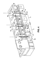
- FIG. 4 shows a three-dimensional perspective cut-away view of a terminal bracket 12 connected to the terminal barrels (e.g., phase A terminal barrel 6, phase B terminal barrel 8 and phase C terminal barrel 10). It is understood that terminal bracket 12 and terminal barrels 6, 8, 10 may be substantially similar to those conventional terminal brackets and terminal barrels described herein. Also shown in this cut-away view is the phase selection member 16, including the conductive strip 18 and the actuation member holder 20 operably connected (e.g., slideably connected) to the conductive strip 18. In one embodiment, the actuation member holder 20 may rest within a recess (e.g., a pocket) 32 in the terminal bracket 12.
- a recess e.g., a pocket
- actuation member holder 20 may be movably (e.g., slideably) engaged with the conductive strip 18 (e.g., via rails, tabs, slideable dovetail matings, rivets, grooves, etc.).
- apertures 22 in the actuation member holder 20 may be mis-aligned with two of the openings 31 in the conductive strip 18, and similarly, mis-aligned with two of the phase A terminal barrel 6, phase B terminal barrel 8 and phase C terminal barrel 10.
- an actuation member 24 (e.g., a screw) is only capable of engaging one terminal barrel (e.g., terminal barrel 8 in this depiction) at a time. It is understood that in order to actuate one of the other terminal barrels (e.g., phase A terminal barrel 6 or phase B terminal barrel 10), actuation member 24 may be removed (e.g., vertically) from opening 31 and aperture 22, actuation member holder 20 may be slid relative to the conductive strip such that a distinct aperture 22 aligns with a distinct opening 31, and the actuation member 24 (or another actuation member) may be placed through the distinct aperture 22 (and corresponding distinct opening 31) to actuate the phase A terminal barrel 6 or phase B terminal barrel 10.
- actuation member 24 e.g., a screw
- phase selection member 16 may include an actuation member holder 20 with only two (2) apertures 22 therein, where the actuation member holder 20 may be movably (e.g., slidably) engaged with the conductive strip 18 such that only one of the two apertures 22 may align with one of the openings 31 in the conductive strip 18 at a given time.
- actuation member holder 20 may include only one aperture 22 therein, where the actuation member holder 20 may be slidably engaged with the conductive strip 18 such that the aperture 22 may align with one of the openings 31 in the conductive strip 18 at a given time.
- each phase terminal barrel e.g., phase A terminal barrel 6, phase B terminal barrel 8 and phase C terminal barrel
- each relay e.g., relay 26
- each relay includes or is connected to a control system allowing for selection of one of the phases (via the phase terminal barrels).
- control of this type of meter may be performed via a remote system (e.g., a central control center system managed by a utility or service provider), where communication between the meter and the remote system is performed via wireless, hardwire, or any other conventional means.
- the meter may include other conventional components such as: transmitter(s), receiver(s), processor(s), memory, etc., descriptions of which are omitted herein for clarity.
- an installer may be able to install the meter (having three relays) without selecting a phase, allowing the control system to dictate phase selection remotely. This may further allow for switching between phases either at the meter itself (e.g., via a user interface) or via the control system. In any case, this embodiment may allow for selection of one of three phases in the electrical meter, thereby reducing an inventory carried by the installer.
Landscapes
- Physics & Mathematics (AREA)
- General Physics & Mathematics (AREA)
- Arrangements For Transmission Of Measured Signals (AREA)
- Measuring Volume Flow (AREA)
- Supply And Distribution Of Alternating Current (AREA)
Abstract
A three-phase selection energy meter (2) is disclosed. In one embodiment, an energy meter (2) includes a base (4); a phase A terminal barrel (6), a phase B terminal barrel (8) and a phase C terminal barrel (10); and a phase selection member (16) movably engaged with the base (4), the phase selection member (16) permitting individual selection of each of the phase A terminal barrel (6), the phase B terminal barrel (8) and the phase C terminal barrel (10), wherein the individual selection of the one of the phase A terminal barrel (6), the phase B terminal barrel (8) or the phase C terminal barrel (10) prohibits selection of the other two of the phase A terminal barrel (6), the phase B terminal barrel (8) and the phase C terminal barrel (10).
Description
- The subject matter disclosed herein relates to a three-phase selectable energy meter. Specifically, the subject matter disclosed herein relates to an energy meter allowing for selection between three phases of power supply.
- In electrical energy distribution networks utilizing three-phase systems, unbalanced loads (e.g., loads carried unevenly across the three phases), may negatively impact performance. Conventionally, e.g., residential power supply is provided using only a single phase, with every third household along the network each receiving power from one of the three phases. This general approximation may average out across the grid, thereby providing substantially uniform load distribution across each of the three phases.
- Recently, energy utilities have requested the ability to control secondary (or, "non-essential") load devices in order to meet target service requirements during times of high demand. Some larger buildings (e.g., large residential buildings, office buildings, etc.) may require three-phase power for devices requiring relatively large power loads (e.g., air conditioning systems). In these cases, the secondary, or non-essential, loads are restricted to a single phase of the three phases.
- In order to ensure that secondary loads are evenly allocated across the three-phase network, meter installers (e.g., human technicians) conventionally carry three different varieties of three-phase meter. Each variety is configured to engage one phase when installed. However, manufacturing three varieties of three-phase meter may be costly, and carrying these three varieties of a three-phase meter may cause the technician to amass an unwieldy inventory of devices.
- The present invention resides in a three-phase selectable energy meter including a base; a phase A terminal barrel, a phase B terminal barrel and a phase C terminal barrel; and a phase selection member movably engaged with the base, the phase selection member permitting individual selection of each of the phase A terminal barrel, the phase B terminal barrel and the phase C terminal barrel, wherein the individual selection of the one of the phase A terminal barrel, the phase B terminal barrel or the phase C terminal barrel prohibits selection of the other two of the phase A terminal barrel, the phase B terminal barrel and the phase C terminal barrel.
- The phase A terminal barrel, the phase B terminal barrel and the phase C terminal barrel may be housed in the base and the meter may further include an actuation member engaged with the phase selection member and only one of the phase A terminal barrel, the phase B terminal barrel and the phase C terminal barrel.
- A relay may also be housed in the base and the phase selection member may include a connecting strip electrically connected to the relay.
- Embodiments of the present invention will now be described, by way of example only, with reference to the accompanying drawings in which:
-
FIG. 1 shows a partial blow-out three-dimensional perspective view of a portion of a three-phase selectable energy meter according to embodiments of the invention. -
FIG. 2 shows a partial blow-out three-dimensional perspective view of portions of a three-phase selectable energy meter according to embodiments of the invention. -
FIG. 3 shows a three-dimensional perspective view of portions of a three-phase selectable energy meter according to embodiments of the invention. -
FIG. 4 shows a three-dimensional perspective view of portions of a three-phase selectable energy meter according to embodiments of the invention. - It is noted that the drawings of the invention are not necessarily to scale. The drawings are intended to depict only typical aspects of the invention, and therefore should not be considered as limiting the scope of the invention. In the drawings, like numbering represents like elements between the drawings.
- Aspects of the invention relate to a three-phase selection energy meter. Specifically, the subject matter disclosed herein relates to an energy meter allowing for selection between three phases of power supply.
- As noted herein, recently, energy utilities are requesting the ability to control secondary (or, "non-essential") load devices in order to meet target service requirements during times of high demand. Some larger buildings (e.g., large residential buildings, office buildings, etc.) may require three-phase power for devices requiring relatively large power loads (e.g., air conditioning systems). In these cases, the secondary, or non-essential, loads are restricted to a single phase of the three phases.
- In order to ensure that secondary loads are evenly allocated across the three-phase network, meter installers (e.g., human technicians) conventionally carry three different varieties of three-phase meter. When the utility aims to reduce the single phase load on one of the three-phase meters, it may be desirable to reduce the load applied evenly across all three phases in the network. In many cases, the technicians are required by a utility to carry three different varieties of three-phase meter. Each variety is configured to engage one phase when installed. However, manufacturing three varieties of a three-phase meter may be costly, and carrying these three varieties of a three-phase meter may cause the technician to amass an unwieldy inventory of devices.
- In contrast to conventional three-phase energy meters, aspects of the invention include a three-phase selectable energy meter that allows a technician to choose one of three phases of operation during installation. That is, the energy meter described according to aspects of the invention allows for selection between each of the three phases of operation, where in some embodiments, only one phase is selectable at a given time.
- As described herein, aspects of the invention include a three-phase selectable energy meter. Turning to
FIG. 1 , a partial blow-out three-dimensional perspective view of portion of a three-phase selectable energy meter (or, meter) 2 is shown according to embodiments of the invention. As shown, the meter 2 may include a base 4, housing a plurality of elements, including terminal barrels, e.g., a phase Aterminal barrel 6, a phaseB terminal barrel 8 and a phase C terminal barrel 10 (generally shown, and partially hidden in this view). It should be noted that theterminal barrels FIG. 3 as this perspective view ofFIG. 1 obstructs full view of those elements. Description of theindividual terminal barrels - It is further understood that although embodiments described herein may include individual
terminal barrels - Returning to
FIG. 1 , also shown in this blow-out view is aterminal bracket 12 configured to couple to the base 4, where theterminal bracket 12 includes a plurality of apertures. In particular,terminal bracket 12 includes a plurality ofapertures 14 corresponding to theterminal barrels terminal barrels terminal bracket 12. Also shown is aphase selection member 16, configured to be movably engaged with the base 4, where the phase selection member permits individual selection of each of the phase Aterminal barrel 6, the phaseB terminal barrel 8 or the phaseC terminal barrel 10. As will be explained further with reference to other Figures included herein, thephase selection member 16 may allow for selection of one of theterminal barrels terminal barrels phase selection member 16 may include a conductive strip 18 (including, e.g., a metal), and anactuation member holder 20 including apertures 22 (three shown). In one embodiment, theapertures 22 may respectively correspond to the phase Aterminal barrel 6, the phaseB terminal barrel 8 and the phaseC terminal barrel 10. Also shown is an actuation member 24 (e.g., a screw, pin, elongated block, etc.) configured to actuate one of theterminal barrels corresponding apertures 14 of theterminal bracket 12. Also shown in the meter 2 ofFIG. 1 are additional conventional components such as arelay 26, and a loadcontrol terminal barrel 28. Description of these components is omitted herein for clarity. -
FIG. 2 shows a partial blow-out three-dimensional perspective view of thephase selection member 16, including theconductive strip 18 and theactuation member holder 20, as well as arelay connection member 30, configured to provide electrical connection between the relay 26 (FIG. 1 ) and one or more of the phase Aterminal barrel 6, the phaseB terminal barrel 8 and the phaseC terminal barrel 10. As shown, threeactuation members 24 are illustrated in this blow-out view. It is understood that during operation, thephase selection member 16 may allow only one of the threeactuation members 24 to engage one of theterminal barrels terminal barrels actuation members 24 may prevent actuation of two of the threeactuation member 24 with their correspondingterminal barrels apertures 22 in theactuation member holder 20 differently thanopenings 31 in theconductive strip 18. That is,openings 31 in theconductive strip 18 may correspond directly to theterminal barrels openings 31 are equally spaced (e.g., a distance "x" apart) along an axis of theconductive strip 18. In contrast,apertures 22 of theactuation member holder 20 may be spaced a distance "a" and/or "b" apart, where at least one of "a" or "b" is distinct from distance "x." In one embodiment,apertures 22 may be equally spaced along an axis of theactuation member holder 20, where distance "a" equals distance "b." In this case, distances "a" and "b" are distinct from distance "x", such that only one of theapertures 22 may align with one of theopenings 31 in theconductive strip 18 at a given time. In another embodiment,apertures 22 may be non-uniformly spaced along the axis of theactuation member holder 20, such that "a" does not equal "b." However, in this case, it is understood that only one of theapertures 22 may align with one of theopenings 31 in theconductive strip 18 at a given time. In any case, at least one spacing between theapertures 22 in theactuation member holder 20 may be distinct from at least one spacing between theopenings 31 in the conductive strip, such that only one pairedaperture 22 andopening 31 may completely receive anactuation member 24 at a given time. This aspect of the invention may prevent accidental engagement of more than one of the phase Aterminal barrel 6, the phaseB terminal barrel 8 or the phaseC terminal barrel 10 at a given time (FIG. 1 ). -
FIG. 3 shows a three-dimensional perspective view of portions of the meter 2 (shown and described inFIG. 1 ), including the base 4, theterminal barrels relay 26, and the loadcontrol terminal barrel 28. Also shown in the example illustrated in this partial view is theconductive strip 18, electrically connected to the terminal barrel 28 (via, e.g., a conventional electrical conduit) and the phase Aterminal barrel 6 via theactuation member 24. While connection with the phase Aterminal barrel 6 is shown in this perspective view, it is understood that one of the phaseB terminal barrel 8 or the phaseC terminal barrel 10 may alternatively be engaged (via a similar actuation member 24). These other scenarios are not specifically illustrated for brevity. It is further understood that in this partial perspective view, theactuation member holder 20 andterminal bracket 12 are omitted. -
FIG. 4 shows a three-dimensional perspective cut-away view of aterminal bracket 12 connected to the terminal barrels (e.g., phase Aterminal barrel 6, phaseB terminal barrel 8 and phase C terminal barrel 10). It is understood thatterminal bracket 12 andterminal barrels phase selection member 16, including theconductive strip 18 and theactuation member holder 20 operably connected (e.g., slideably connected) to theconductive strip 18. In one embodiment, theactuation member holder 20 may rest within a recess (e.g., a pocket) 32 in theterminal bracket 12. In other embodiments,actuation member holder 20 may be movably (e.g., slideably) engaged with the conductive strip 18 (e.g., via rails, tabs, slideable dovetail matings, rivets, grooves, etc.). In any case, as described with reference toFIG. 2 , and as further illustrated in this cut-away view,apertures 22 in theactuation member holder 20 may be mis-aligned with two of theopenings 31 in theconductive strip 18, and similarly, mis-aligned with two of the phase Aterminal barrel 6, phaseB terminal barrel 8 and phaseC terminal barrel 10. As shown, an actuation member 24 (e.g., a screw) is only capable of engaging one terminal barrel (e.g.,terminal barrel 8 in this depiction) at a time. It is understood that in order to actuate one of the other terminal barrels (e.g., phase Aterminal barrel 6 or phase B terminal barrel 10),actuation member 24 may be removed (e.g., vertically) from opening 31 andaperture 22,actuation member holder 20 may be slid relative to the conductive strip such that adistinct aperture 22 aligns with adistinct opening 31, and the actuation member 24 (or another actuation member) may be placed through the distinct aperture 22 (and corresponding distinct opening 31) to actuate the phase Aterminal barrel 6 or phaseB terminal barrel 10. - Returning to
FIG. 1 , it is understood that as described herein, the meter 2 including aphase selection member 16 may permit individual selection of one of a plurality of phases (via e.g., the phase Aterminal barrel 6, the phaseB terminal barrel 8 or the phase C terminal barrel 10) while preventing selection of the other ones of the plurality of phases, thereby allowing a technician (e.g., a human technician) to select only one phase during installation. This may also allow the technician to carry a single three-phase selectable meter (e.g., meter 2) that may be selectively configured as needed (via actuation member(s) 24) for phase selection across all three phases. - It is understood that alternative embodiments of the
phase selection member 16 are also possible in keeping with the teachings of aspects of the invention. That is, in some cases, thephase selection member 16 may include anactuation member holder 20 with only two (2)apertures 22 therein, where theactuation member holder 20 may be movably (e.g., slidably) engaged with theconductive strip 18 such that only one of the twoapertures 22 may align with one of theopenings 31 in theconductive strip 18 at a given time. It is further understood that in another embodiment,actuation member holder 20 may include only oneaperture 22 therein, where theactuation member holder 20 may be slidably engaged with theconductive strip 18 such that theaperture 22 may align with one of theopenings 31 in theconductive strip 18 at a given time. - In yet another embodiment, a plurality of relays 26 (
FIG. 1 ), e.g., threeseparate relays 26 may be used to provide the three-phase selectable features described herein. In this case, each phase terminal barrel (e.g., phase Aterminal barrel 6, phaseB terminal barrel 8 and phase C terminal barrel 10) can be respectively connected to a relay (e.g., relay 26), where each relay (e.g., relay 26) includes or is connected to a control system allowing for selection of one of the phases (via the phase terminal barrels). In one embodiment, control of this type of meter may be performed via a remote system (e.g., a central control center system managed by a utility or service provider), where communication between the meter and the remote system is performed via wireless, hardwire, or any other conventional means. It is understood that in this embodiment the meter may include other conventional components such as: transmitter(s), receiver(s), processor(s), memory, etc., descriptions of which are omitted herein for clarity. In this embodiment, an installer may be able to install the meter (having three relays) without selecting a phase, allowing the control system to dictate phase selection remotely. This may further allow for switching between phases either at the meter itself (e.g., via a user interface) or via the control system. In any case, this embodiment may allow for selection of one of three phases in the electrical meter, thereby reducing an inventory carried by the installer. - The terminology used herein is for the purpose of describing particular embodiments only and is not intended to be limiting of the disclosure. As used herein, the singular forms "a", "an" and "the" are intended to include the plural forms as well, unless the context clearly indicates otherwise. It will be further understood that the terms "comprises" and/or "comprising," when used in this specification, specify the presence of stated features, integers, steps, operations, elements, and/or components, but do not preclude the presence or addition of one or more other features, integers, steps, operations, elements, components, and/or groups thereof.
- This written description uses examples to disclose the invention, including the best mode, and also to enable any person skilled in the art to practice the invention, including making and using any devices or systems and performing any incorporated methods. The patentable scope of the invention is defined by the claims, and may include other examples that occur to those skilled in the art. Such other examples are intended to be within the scope of the claims if they have structural elements that do not differ from the literal language of the claims, or if they include equivalent structural elements with insubstantial differences from the literal languages of the claims.
Claims (8)
- A three-phase selectable energy meter (2) comprising:a base (4);a phase A terminal barrel (6), a phase B terminal barrel (8) and a phase C terminal barrel (10); anda phase selection member (16) movably engaged with the base (4), the phase selection member (16) permitting individual selection of each of the phase A terminal barrel (6), the phase B terminal barrel (8) and the phase C terminal barrel (10), wherein the individual selection of the one of the phase A terminal barrel (6), the phase B terminal barrel (8) or the phase C terminal barrel (10) prohibits selection of the other two of the phase A terminal barrel (6), the phase B terminal barrel (8) and the phase C terminal barrel (10).
- The three-phase selectable energy meter (2) of claim 1, wherein the base (4) houses the phase A terminal barrel (6), the phase B terminal barrel (8) and the phase C terminal barrel (10); and further comprising:an actuation member (24) engaged with the phase selection member (16) and only one of the phase A terminal barrel (6), the phase B terminal barrel (8) and the phase C terminal barrel (10).
- The three-phase selectable energy meter (2) of claim 1, wherein the base (4) further houses a relay (26) and wherein the phase selection member (16) includes a connecting strip electrically connected to the relay (26).
- The three-phase selectable energy meter (2) of any of claims 1 to 3, further comprising: a terminal bracket (12) coupled to the base (4) and the phase selection member (16), the terminal bracket (12) including an aperture (14) corresponding to each of: the phase A terminal barrel (6), the phase B terminal barrel (8) and the phase C terminal barrel (10).
- The three-phase selectable energy meter (2) of claim 4, wherein the individual selection of the one of the phase A terminal barrel (6), the phase B terminal barrel (8) or the phase C terminal barrel (10) includes actuating the one of the phase A terminal barrel (6), the phase B terminal barrel (8) or the phase C terminal barrel (10) via the corresponding aperture (14) of the terminal bracket (12).
- The three-phase selectable energy meter (2) of any of claims 1 to 3, wherein the phase selection member (16) includes:a conductive strip (18); andan actuation member holder (20) movably attached to the conductive strip (18), the actuation member holder (20) including three apertures (22) respectively corresponding to the phase A terminal barrel (6), the phase B terminal barrel (8) and the phase C terminal barrel (10).
- The three-phase selectable energy meter (2) of claim 6, further comprising:a terminal bracket (12) coupled to the base (4) and the phase selection member (16), the terminal bracket (12) including three apertures (14) respectively corresponding to the phase A terminal barrel (6), the phase B terminal barrel (8) and the phase C terminal barrel (10);wherein the three apertures (14) are uniformly separated by a first distance; and
wherein at least two of the three apertures (22) of the actuation member holder (20) are separated from one another by a second distance distinct from the first distance. - The three-phase selectable energy meter (2) of claim 7, wherein one of the three apertures (22) of the actuation member holder (20) is configured to align with one of the three apertures (14) of the terminal bracket (12), simultaneously misaligning two of the three apertures (22) of the actuation member holder (20) with two of the three apertures (14) of the terminal bracket (12).
Applications Claiming Priority (1)
| Application Number | Priority Date | Filing Date | Title |
|---|---|---|---|
| US13/047,459 US8405383B2 (en) | 2011-03-14 | 2011-03-14 | Three-phase selectable energy meter |
Publications (1)
| Publication Number | Publication Date |
|---|---|
| EP2500734A1 true EP2500734A1 (en) | 2012-09-19 |
Family
ID=45841270
Family Applications (1)
| Application Number | Title | Priority Date | Filing Date |
|---|---|---|---|
| EP12158303A Withdrawn EP2500734A1 (en) | 2011-03-14 | 2012-03-06 | Three-phase energy meter with phase selection means for single phase metering |
Country Status (7)
| Country | Link |
|---|---|
| US (1) | US8405383B2 (en) |
| EP (1) | EP2500734A1 (en) |
| JP (1) | JP2012200137A (en) |
| AU (1) | AU2012201486A1 (en) |
| BR (1) | BR102012005580A2 (en) |
| CA (1) | CA2770682A1 (en) |
| NZ (1) | NZ598768A (en) |
Families Citing this family (21)
| Publication number | Priority date | Publication date | Assignee | Title |
|---|---|---|---|---|
| US9329659B2 (en) | 2013-02-06 | 2016-05-03 | Veris Industries, Llc | Power monitoring system that determines frequency and phase relationships |
| CN103267893B (en) * | 2013-06-04 | 2015-10-28 | 长沙高升电子电器科技有限公司 | Balanced distribution intelligent electric meter |
| CN104517777B (en) * | 2013-09-30 | 2016-05-25 | 景德镇景光精盛电器有限公司 | Any phase-change switch of a kind of permanent magnet vacuum |
| US10408911B2 (en) | 2015-12-28 | 2019-09-10 | Veris Industries, Llc | Network configurable system for a power meter |
| US10274572B2 (en) | 2015-12-28 | 2019-04-30 | Veris Industries, Llc | Calibration system for a power meter |
| US10371721B2 (en) | 2015-12-28 | 2019-08-06 | Veris Industries, Llc | Configuration system for a power meter |
| US10371730B2 (en) | 2015-12-28 | 2019-08-06 | Veris Industries, Llc | Branch current monitor with client level access |
| DE112016007223B4 (en) * | 2016-10-13 | 2025-08-28 | Ford Motor Company | Dual-mode augmented reality interfaces for mobile devices |
| US11215650B2 (en) | 2017-02-28 | 2022-01-04 | Veris Industries, Llc | Phase aligned branch energy meter |
| US11193958B2 (en) | 2017-03-03 | 2021-12-07 | Veris Industries, Llc | Non-contact voltage sensor |
| CN108802460B (en) * | 2017-05-04 | 2024-01-30 | 郑州三晖电气股份有限公司 | Compatible electric energy meter base and method for realizing compatibility |
| US10705126B2 (en) | 2017-05-19 | 2020-07-07 | Veris Industries, Llc | Energy metering with temperature monitoring |
| US11674988B2 (en) | 2019-03-11 | 2023-06-13 | Honeywell International Inc. | Power meter with emulation capability |
| US10989745B2 (en) * | 2019-03-11 | 2021-04-27 | Honeywell International Inc. | Power meter with fixed segment interactive menu |
| US11137426B2 (en) | 2019-03-11 | 2021-10-05 | Honeywell International Inc. | Power meter with master/slave functionality |
| US11119123B2 (en) * | 2019-03-11 | 2021-09-14 | Honeywell International Inc. | Power meter with movable terminal blocks |
| US10955515B2 (en) * | 2019-03-11 | 2021-03-23 | Honeywell International Inc. | Calibrating a power meter with a current transformer in the field |
| US11019194B2 (en) | 2019-03-12 | 2021-05-25 | Honeywell International Inc. | Commissioning power meters with a mobile device |
| JP1641301S (en) * | 2019-04-12 | 2019-09-17 | ||
| CN112216562A (en) * | 2019-12-20 | 2021-01-12 | 青岛鼎信通讯股份有限公司 | Three-phase meter magnetic latching relay with manganin shunt |
| US11499651B2 (en) | 2020-06-23 | 2022-11-15 | Honeywell International Inc. | Switchless valve position detection system |
Citations (5)
| Publication number | Priority date | Publication date | Assignee | Title |
|---|---|---|---|---|
| GB346640A (en) * | 1929-08-10 | 1931-04-16 | Landis & Gyr Sa | An improved terminal block for electricity meters and other measuring instruments |
| DE3622771A1 (en) * | 1986-07-07 | 1988-01-21 | Stepper & Co | Arrangement for energy measurement in two separate, multi-phase supply circuits |
| JPH04128658A (en) * | 1990-09-20 | 1992-04-30 | Toshiba Corp | Single-phase two-wire type watt-hour meter |
| JP2006084374A (en) * | 2004-09-17 | 2006-03-30 | Chudenko Corp | Short-circuit prevention device for low-voltage electric meters |
| US20070205663A1 (en) * | 2006-03-02 | 2007-09-06 | Tyco Electronics Power Systems, Inc. | Apparatus and method for distributing electrical power from a plurality of power sources among a plurality of electrical conductors |
Family Cites Families (14)
| Publication number | Priority date | Publication date | Assignee | Title |
|---|---|---|---|---|
| US3909900A (en) * | 1974-05-22 | 1975-10-07 | Artos Engineering Co | Apparatus for producing electrical conductors |
| US4023101A (en) | 1975-08-20 | 1977-05-10 | Christoffer Virgil F | Multiple function electrical measuring and indicating apparatus |
| DE4202655A1 (en) | 1992-01-31 | 1993-08-05 | Peter Schieritz | Test instrument for single and three=phase equipment - has phase selection switching, earth continuity and conductivity verification and phase sequence indication |
| CN2147542Y (en) | 1992-09-24 | 1993-11-24 | 杨金贵 | Scan digital display three-phase electric voltage (current) meter |
| US6937003B2 (en) * | 2002-03-26 | 2005-08-30 | Veris Industries, Llc | Power monitoring system |
| JP4324846B2 (en) * | 2003-06-13 | 2009-09-02 | アイシン・エィ・ダブリュ株式会社 | Electric motor drive current detection device |
| JP2006112968A (en) * | 2004-10-15 | 2006-04-27 | Toyota Motor Corp | Current detector |
| US8233569B2 (en) * | 2006-09-28 | 2012-07-31 | Tektronix, Inc. | Realtime spectrum trigger system on realtime oscilloscope |
| CN201060252Y (en) | 2007-05-18 | 2008-05-14 | 天津市百利电气有限公司 | Three phase electronic type over loading relay tester |
| US8269480B2 (en) * | 2007-07-09 | 2012-09-18 | Ltx-Credence Corporation | Method and apparatus for identifying and reducing spurious frequency components |
| US7693670B2 (en) | 2007-08-14 | 2010-04-06 | General Electric Company | Cognitive electric power meter |
| US8212548B2 (en) * | 2008-06-02 | 2012-07-03 | Veris Industries, Llc | Branch meter with configurable sensor strip arrangement |
| US8294453B2 (en) * | 2009-05-21 | 2012-10-23 | Veris Industries, Llc | Externally reporting branch power monitoring system |
| US8138626B2 (en) * | 2009-10-25 | 2012-03-20 | Greenwave Reality, Pte Ltd. | Power node for energy management |
-
2011
- 2011-03-14 US US13/047,459 patent/US8405383B2/en not_active Expired - Fee Related
-
2012
- 2012-03-06 EP EP12158303A patent/EP2500734A1/en not_active Withdrawn
- 2012-03-08 JP JP2012051110A patent/JP2012200137A/en active Pending
- 2012-03-08 CA CA2770682A patent/CA2770682A1/en not_active Abandoned
- 2012-03-13 AU AU2012201486A patent/AU2012201486A1/en not_active Abandoned
- 2012-03-13 NZ NZ598768A patent/NZ598768A/en not_active IP Right Cessation
- 2012-03-13 BR BR102012005580-5A patent/BR102012005580A2/en not_active Application Discontinuation
Patent Citations (5)
| Publication number | Priority date | Publication date | Assignee | Title |
|---|---|---|---|---|
| GB346640A (en) * | 1929-08-10 | 1931-04-16 | Landis & Gyr Sa | An improved terminal block for electricity meters and other measuring instruments |
| DE3622771A1 (en) * | 1986-07-07 | 1988-01-21 | Stepper & Co | Arrangement for energy measurement in two separate, multi-phase supply circuits |
| JPH04128658A (en) * | 1990-09-20 | 1992-04-30 | Toshiba Corp | Single-phase two-wire type watt-hour meter |
| JP2006084374A (en) * | 2004-09-17 | 2006-03-30 | Chudenko Corp | Short-circuit prevention device for low-voltage electric meters |
| US20070205663A1 (en) * | 2006-03-02 | 2007-09-06 | Tyco Electronics Power Systems, Inc. | Apparatus and method for distributing electrical power from a plurality of power sources among a plurality of electrical conductors |
Non-Patent Citations (1)
| Title |
|---|
| ANONYMOUS: "EPM 5200/5300/5350 Power Metering System, Instruction Manual", 2007, pages 1 - 31, XP002679034, Retrieved from the Internet <URL:http://www.gedigitalenergy.com/products/manuals/epm/GEK-106557B.pdf> [retrieved on 20120629] * |
Also Published As
| Publication number | Publication date |
|---|---|
| BR102012005580A2 (en) | 2019-06-04 |
| US20120235667A1 (en) | 2012-09-20 |
| US8405383B2 (en) | 2013-03-26 |
| NZ598768A (en) | 2013-09-27 |
| JP2012200137A (en) | 2012-10-18 |
| AU2012201486A1 (en) | 2012-10-04 |
| CA2770682A1 (en) | 2012-09-14 |
Similar Documents
| Publication | Publication Date | Title |
|---|---|---|
| US8405383B2 (en) | Three-phase selectable energy meter | |
| US12402009B2 (en) | Communication enabled circuit breakers and circuit breaker panels | |
| US12237689B2 (en) | Integrated electrical panel | |
| US8719123B2 (en) | Reporting circuit breaker and system | |
| US11919417B2 (en) | Load management system and method for managing loads in a power distribution grid | |
| AU2020350671A1 (en) | Systems and methods for managing electrical loads | |
| US20160224083A1 (en) | Addressable Electrical Outlets | |
| AU2021205427B2 (en) | Storage system configured for use with an energy management system | |
| CN102792550A (en) | Method and device for energy management | |
| JP2016220143A (en) | Remote meter reading system | |
| RU2608387C1 (en) | Electric vehicles charging system controlling and monitoring system and method | |
| CN108233385A (en) | The work monitoring method and device of home appliance | |
| CA3164419C (en) | Storage system configured for use with an energy management system | |
| Ornelas et al. | First step towards a smart grid communication architecture for the brazilian federal district | |
| WO2025034864A1 (en) | Load management systems for electric grids | |
| CN122003793A (en) | Power grid load management system |
Legal Events
| Date | Code | Title | Description |
|---|---|---|---|
| PUAI | Public reference made under article 153(3) epc to a published international application that has entered the european phase |
Free format text: ORIGINAL CODE: 0009012 |
|
| AK | Designated contracting states |
Kind code of ref document: A1 Designated state(s): AL AT BE BG CH CY CZ DE DK EE ES FI FR GB GR HR HU IE IS IT LI LT LU LV MC MK MT NL NO PL PT RO RS SE SI SK SM TR |
|
| AX | Request for extension of the european patent |
Extension state: BA ME |
|
| 17P | Request for examination filed |
Effective date: 20130319 |
|
| STAA | Information on the status of an ep patent application or granted ep patent |
Free format text: STATUS: THE APPLICATION IS DEEMED TO BE WITHDRAWN |
|
| 18D | Application deemed to be withdrawn |
Effective date: 20151001 |