EP2500607A1 - Piston with integral seals for a water softener control valve - Google Patents
Piston with integral seals for a water softener control valve Download PDFInfo
- Publication number
- EP2500607A1 EP2500607A1 EP20120152361 EP12152361A EP2500607A1 EP 2500607 A1 EP2500607 A1 EP 2500607A1 EP 20120152361 EP20120152361 EP 20120152361 EP 12152361 A EP12152361 A EP 12152361A EP 2500607 A1 EP2500607 A1 EP 2500607A1
- Authority
- EP
- European Patent Office
- Prior art keywords
- piston
- flange
- sealing ring
- recited
- groove
- Prior art date
- Legal status (The legal status is an assumption and is not a legal conclusion. Google has not performed a legal analysis and makes no representation as to the accuracy of the status listed.)
- Granted
Links
- XLYOFNOQVPJJNP-UHFFFAOYSA-N water Substances O XLYOFNOQVPJJNP-UHFFFAOYSA-N 0.000 title claims abstract description 58
- 238000007789 sealing Methods 0.000 claims abstract description 44
- 230000002093 peripheral effect Effects 0.000 claims abstract description 14
- 238000000034 method Methods 0.000 claims description 13
- 239000000463 material Substances 0.000 claims description 8
- 238000005495 investment casting Methods 0.000 claims description 5
- 229920001971 elastomer Polymers 0.000 claims description 4
- 238000000465 moulding Methods 0.000 claims description 3
- 238000004519 manufacturing process Methods 0.000 claims description 2
- 239000004033 plastic Substances 0.000 claims description 2
- 229910001220 stainless steel Inorganic materials 0.000 claims description 2
- 239000010935 stainless steel Substances 0.000 claims description 2
- 239000012858 resilient material Substances 0.000 claims 1
- 239000011347 resin Substances 0.000 description 27
- 229920005989 resin Polymers 0.000 description 27
- 230000008929 regeneration Effects 0.000 description 19
- 238000011069 regeneration method Methods 0.000 description 19
- 239000012267 brine Substances 0.000 description 13
- HPALAKNZSZLMCH-UHFFFAOYSA-M sodium;chloride;hydrate Chemical compound O.[Na+].[Cl-] HPALAKNZSZLMCH-UHFFFAOYSA-M 0.000 description 13
- 150000002500 ions Chemical class 0.000 description 12
- 239000008233 hard water Substances 0.000 description 10
- FAPWRFPIFSIZLT-UHFFFAOYSA-M Sodium chloride Chemical compound [Na+].[Cl-] FAPWRFPIFSIZLT-UHFFFAOYSA-M 0.000 description 5
- WCUXLLCKKVVCTQ-UHFFFAOYSA-M Potassium chloride Chemical compound [Cl-].[K+] WCUXLLCKKVVCTQ-UHFFFAOYSA-M 0.000 description 4
- 229910052500 inorganic mineral Inorganic materials 0.000 description 4
- 239000011707 mineral Substances 0.000 description 4
- 235000010755 mineral Nutrition 0.000 description 4
- 235000002639 sodium chloride Nutrition 0.000 description 4
- 239000000243 solution Substances 0.000 description 4
- 239000012492 regenerant Substances 0.000 description 3
- 239000011780 sodium chloride Substances 0.000 description 3
- 230000003466 anti-cipated effect Effects 0.000 description 2
- 238000009937 brining Methods 0.000 description 2
- 239000003599 detergent Substances 0.000 description 2
- 239000012535 impurity Substances 0.000 description 2
- 235000011164 potassium chloride Nutrition 0.000 description 2
- 239000001103 potassium chloride Substances 0.000 description 2
- 230000001172 regenerating effect Effects 0.000 description 2
- 239000000344 soap Substances 0.000 description 2
- NWUYHJFMYQTDRP-UHFFFAOYSA-N 1,2-bis(ethenyl)benzene;1-ethenyl-2-ethylbenzene;styrene Chemical compound C=CC1=CC=CC=C1.CCC1=CC=CC=C1C=C.C=CC1=CC=CC=C1C=C NWUYHJFMYQTDRP-UHFFFAOYSA-N 0.000 description 1
- DGAQECJNVWCQMB-PUAWFVPOSA-M Ilexoside XXIX Chemical compound C[C@@H]1CC[C@@]2(CC[C@@]3(C(=CC[C@H]4[C@]3(CC[C@@H]5[C@@]4(CC[C@@H](C5(C)C)OS(=O)(=O)[O-])C)C)[C@@H]2[C@]1(C)O)C)C(=O)O[C@H]6[C@@H]([C@H]([C@@H]([C@H](O6)CO)O)O)O.[Na+] DGAQECJNVWCQMB-PUAWFVPOSA-M 0.000 description 1
- 238000011001 backwashing Methods 0.000 description 1
- 238000005266 casting Methods 0.000 description 1
- 238000004140 cleaning Methods 0.000 description 1
- 238000005260 corrosion Methods 0.000 description 1
- 230000007797 corrosion Effects 0.000 description 1
- 230000003292 diminished effect Effects 0.000 description 1
- 238000001704 evaporation Methods 0.000 description 1
- 230000008020 evaporation Effects 0.000 description 1
- 239000012530 fluid Substances 0.000 description 1
- 238000011010 flushing procedure Methods 0.000 description 1
- 238000009434 installation Methods 0.000 description 1
- 238000005342 ion exchange Methods 0.000 description 1
- 239000003456 ion exchange resin Substances 0.000 description 1
- 229920003303 ion-exchange polymer Polymers 0.000 description 1
- 238000005259 measurement Methods 0.000 description 1
- 229910052751 metal Inorganic materials 0.000 description 1
- 239000002184 metal Substances 0.000 description 1
- 239000002245 particle Substances 0.000 description 1
- 230000000737 periodic effect Effects 0.000 description 1
- 238000009428 plumbing Methods 0.000 description 1
- 229910001414 potassium ion Inorganic materials 0.000 description 1
- 239000002244 precipitate Substances 0.000 description 1
- 238000001556 precipitation Methods 0.000 description 1
- 150000003839 salts Chemical class 0.000 description 1
- 239000011734 sodium Substances 0.000 description 1
- 229910001415 sodium ion Inorganic materials 0.000 description 1
- 239000008234 soft water Substances 0.000 description 1
- 229920002725 thermoplastic elastomer Polymers 0.000 description 1
Images
Classifications
-
- F—MECHANICAL ENGINEERING; LIGHTING; HEATING; WEAPONS; BLASTING
- F16—ENGINEERING ELEMENTS AND UNITS; GENERAL MEASURES FOR PRODUCING AND MAINTAINING EFFECTIVE FUNCTIONING OF MACHINES OR INSTALLATIONS; THERMAL INSULATION IN GENERAL
- F16K—VALVES; TAPS; COCKS; ACTUATING-FLOATS; DEVICES FOR VENTING OR AERATING
- F16K11/00—Multiple-way valves, e.g. mixing valves; Pipe fittings incorporating such valves
- F16K11/02—Multiple-way valves, e.g. mixing valves; Pipe fittings incorporating such valves with all movable sealing faces moving as one unit
- F16K11/06—Multiple-way valves, e.g. mixing valves; Pipe fittings incorporating such valves with all movable sealing faces moving as one unit comprising only sliding valves, i.e. sliding closure elements
- F16K11/065—Multiple-way valves, e.g. mixing valves; Pipe fittings incorporating such valves with all movable sealing faces moving as one unit comprising only sliding valves, i.e. sliding closure elements with linearly sliding closure members
- F16K11/07—Multiple-way valves, e.g. mixing valves; Pipe fittings incorporating such valves with all movable sealing faces moving as one unit comprising only sliding valves, i.e. sliding closure elements with linearly sliding closure members with cylindrical slides
- F16K11/0712—Multiple-way valves, e.g. mixing valves; Pipe fittings incorporating such valves with all movable sealing faces moving as one unit comprising only sliding valves, i.e. sliding closure elements with linearly sliding closure members with cylindrical slides comprising particular spool-valve sealing means
-
- Y—GENERAL TAGGING OF NEW TECHNOLOGICAL DEVELOPMENTS; GENERAL TAGGING OF CROSS-SECTIONAL TECHNOLOGIES SPANNING OVER SEVERAL SECTIONS OF THE IPC; TECHNICAL SUBJECTS COVERED BY FORMER USPC CROSS-REFERENCE ART COLLECTIONS [XRACs] AND DIGESTS
- Y10—TECHNICAL SUBJECTS COVERED BY FORMER USPC
- Y10T—TECHNICAL SUBJECTS COVERED BY FORMER US CLASSIFICATION
- Y10T137/00—Fluid handling
- Y10T137/8593—Systems
- Y10T137/86493—Multi-way valve unit
- Y10T137/86718—Dividing into parallel flow paths with recombining
- Y10T137/86726—Valve with bypass connections
-
- Y—GENERAL TAGGING OF NEW TECHNOLOGICAL DEVELOPMENTS; GENERAL TAGGING OF CROSS-SECTIONAL TECHNOLOGIES SPANNING OVER SEVERAL SECTIONS OF THE IPC; TECHNICAL SUBJECTS COVERED BY FORMER USPC CROSS-REFERENCE ART COLLECTIONS [XRACs] AND DIGESTS
- Y10—TECHNICAL SUBJECTS COVERED BY FORMER USPC
- Y10T—TECHNICAL SUBJECTS COVERED BY FORMER US CLASSIFICATION
- Y10T137/00—Fluid handling
- Y10T137/8593—Systems
- Y10T137/86493—Multi-way valve unit
- Y10T137/86879—Reciprocating valve unit
Definitions
- the present invention relates to apparatus for softening water; and more particularly to systems for controlling regeneration of the resin in a water softening apparatus.
- a water softener in the plumbing system of a building that is supplied with hard water.
- the most common kind of water softener is an ion exchange apparatus that has a tank which holds a bed of resin through which the hard water flows to remove undesirable minerals and other impurities. Binding sites in the resin bed initially contain positive ions, commonly unipositive sodium or potassium ions. As hard water enters the resin, competition for the binding sites occurs. The di-positive and tri-positive ions in the hard water are favored due to their higher charge densities and displace the unipositive ions. Two or three unipositive ions are displaced for each di-positive or tri-positive ion, respectively.
- the capacity of the rein bed to absorb minerals and impurities is finite and eventually ceases to soften the water when a large percentage of the sites become occupied by the di-positive and tri-positive ions.
- a regenerant typically a solution of sodium chloride or potassium chloride.
- the concentration of unipositive ions in the regenerant is sufficiently high to offset the unfavorable electrostatic competition and the binding sites are recovered by unipositive ions.
- the interval of time between regeneration periods during which water softening takes place is referred to as a service mode of operation.
- demand-type water softener controls have been developed which determine the remaining capacity of the resin bed to soften water.
- One type of such an improved control system employed a flow meter that measures the volume of water being treated and regenerates the resin bed when a specified volume of water has flowed through the softener since the previous regeneration. While this type of system is adequate in many installations, municipal systems alternately may draw water from several wells which contain water having different degrees of hardness. In that case, the exhaustion of the resin bed is not a direct function of the volume of water which has been treated since the previous regeneration.
- the valve has several positions corresponding to the backwashing, brining, rinsing and brine replenishing steps of the regeneration process.
- the conventional valves have a body with a bore that has several chambers to which the inlet, outlet and internal passages of the water softener are connected.
- a piston with recesses and lands slides within the bore to selectively interconnect the different chambers and thereby direct water in different paths through the valve depending on the stage of operation.
- Separate sealing rings are placed in annular grooves in the bore between chambers. The seals engage the lands of the piston to block undesired water flow between the chambers. Several manufacturing steps are required to accurately place each sealing ring in the respective groove.
- a piston for a control valve of a water treatment apparatus includes a body with a central portion from which one or more flanges project radially outward.
- Each flange has an outer peripheral surface extending around the central portion with an annular groove therein.
- the annular groove in undercut, thereby having a width that increases from the outer peripheral surface radially inward into the flange.
- a separate sealing ring is located within the annular groove of each flange and is captivated therein by the increasing width of the groove.
- the control valve piston can be fabricated by forming the body using an investment casting process in which the grooves are defined by lost material, such as wax for example. This enables each groove to be undercut thereby forming a structure to captivate the sealing ring.
- the body After the body has hardened, it is placed in a second mold to form the sealing rings.
- This second mold has a cavity in which the valve piston body fits leaving small voids around each flange, that then are filled with the material for the sealing rings which flows into the flange grooves. After the sealing rings have hardened, the second mold is opened and the completed valve piston is removed.
- a water softener 10 includes a treatment tank 12 which contains a bed 14 of ion exchange resin particles.
- a control valve 16 is fixed to the top of the treatment tank 12.
- hard water to be softened is supplied to an inlet passage 18 from which water flows to inlets 20 at the top of the treatment tank and then flows through the resin bed to absorb minerals from the water.
- An outlet conduit 22 extends through the bed 14 from a point adjacent the bottom of the treatment tank 12 to an outlet passage 24 in the control valve 16. Water that has been treated in the resin bed 14 flows through the outlet conduit 22 into the valve's outlet passage 24 from which the water exits the water softener 10 into the pipes in a building.
- the resin bed 14 eventually becomes exhausted and no longer is capable of softening the water.
- a controller 26 initiates a standard regeneration process.
- the controller 26 is fixed to the top of the valve and has a motor 28 that is adapted to drive a valve piston 30 within a circular bore 15 of the control valve 16 through a slowly moving and uninterrupted reciprocating cycle.
- the passages of the control valve 16 are connected in several combinations to direct water through different paths for the various stages of the regeneration process.
- a typical resin bed regeneration process commences with a backwash step in which hard water is directed from the control valve into the outlet conduit 22 and upwards through the resin bed 14 finally exiting the water softener via a drain passage (not shown).
- the backwash step is followed by a brining step.
- the control valve 16 has an injector 32 that is connected by a conduit 34 through a shut-off valve 36 and a tube 38 to a brine tank 40.
- the brine tank 40 contains a brine solution 42 of a common salt, such as a sodium chloride or potassium chloride.
- a partial vacuum created by the flow of hard water through the injector 32 withdraws brine from the brine tank 40 through conduits 29 and 27 and into the treatment tank 12.
- the concentrated brine solution replaces the di-positive and tri-positive ions in the resin bed 14 with unipositive ions recharging the bed.
- a check valve 44 closes to prevent air from being injected into the system and water continues to flow through the injector 32 free of brine. This water propels the brine solution from the treatment tank 12 and then rinses the bed 14 to remove residual brine.
- the brine tank 40 is refilled with water and the softener resin bed 14 is purged. This is accomplished by feeding water into the brine tank 40 through the open shut-off valve 36 and into the treatment tank 12 through the inlets 20. Water passing through the resin bed 14 exits via the drain passage. Thereafter, the control valve 16 is returned to the position that places the water softener 10 into the previously described service mode in which the water for the building in treated.
- the control valve 16 has a novel piston 30 with a central portion, or shaft, 50 from which a plurality of circular disk-shaped flanges 51, 52 and 53 project radially outward, thereby forming recesses 54 and 55 between the flanges.
- a rod-like stem 56 extends axially from one end of the central portion 50 and is adapted for attaching to the mechanism of the controller 26, which moves the piston 30 within the bore 15 of the control valve 16 during the regeneration mode.
- the central portion 50, flanges 51-53 and the stem 56 form a body piston (30) of the valve piston 30 that preferably is fabricated of stainless steel or other corrosion resistant material.
- Each flange 51, 52 and 53 has an outer circumferentially peripheral surface 57, 58 and 59, respectively, extending around the central portion 50 with an annular groove in that surface.
- a separate sealing ring 61, 62 or 63 is located within each of the annular grooves in the peripheral surface 57, 58 and 59, respectively.
- the sealing ring 61-63 are made of rubber, such as a cross-linked thermal set rubber, or a resilient plastic, such as a thermoplastic elastomer.
- Each sealing ring 61-63 projects outward from the respective flange 51-53 and engages the inside surface of the control valve bore 15. That engagement prevents fluid within the recesses 54 or 55 from flowing between a flange and the surface of the valve bore 15 (see Figure 1 ).
- Figure 3 illustrates the cross section through the sealing ring 61 located in the groove 66 in the peripheral surface 57 of one of the flanges 51.
- the annular groove 66 has a dove tail cross section that is undercut so that the interior surface is wider than the opening of the groove through the peripheral surface 58 of the flange 52.
- the undercut captivates the sealing ring 61 within the annular groove 66 and prevents the sealing ring from being pulled out of that groove by forces produced by water flowing through the assembled control valve 16. This is a design requirement because as the piston 30 moves within the bore 15 opening and closing paths through the control valve, water rushes past the peripheral surfaces 57 of the piston flanges creating forces that tend to dislodge the sealing rings.
- Figure 4 illustrates a second style of sealing ring 70 located in a groove 72 in the peripheral surface 58 of one of the flanges 52.
- the groove 72 has T-shaped cross section in which an inner region 74 has a width that is larger than the width of the groove in an outer region 76 at the peripheral surface 58 of the flange.
- the sealing ring 70 is enlarged in that inner region 74, thereby captivating the sealing ring in the groove 72.
- This style of sealing ring 70 has a pair of lobes 78 which engage the interior surface of the valve bore 15.
- a third style of sealing ring 80 is shown in Figure 5 located in an identical annular groove 72 in one of the flanges 52.
- This style of sealing ring 80 has three lobes 82 which engage the interior surface of the valve bore 15.
- the valve piston 30 is fabricated by first producing the body 60 using an investment casting process, such as lost wax casting.
- the mold for this casting process includes material, such as wax, which defines the grooves in the outer circumferentially peripheral surfaces of the flanges 51-53. Because this material can be easily removed after the material of the body 60 has hardened, the grooves can be undercut to provide a groove in which the sealing rings are locked in place, as described previously.
- This second mold has a cavity in which the body 60 of the valve piston 30 fits leaving small voids around each flange, which then are filled with the material for the sealing rings which flows into the entire groove 57-59 in the respective flange 51-53. After the sealing rings have hardened, the second mold is opened and the completed valve piston 30 is removed.
- the sealing rings 61-63 By over molding the sealing rings 61-63 into the grooves of the metal portion of the piston 30, the sealing rings become locked within the grooves and are not easily removed, such as due to the force from the water flowing through the assembled control valve 16. If non-locking type grooves were used with resilient sealing rings merely stretched around the flanges 51-56 and then released into the grooves, the sealing rings might not be held in place securely enough to resist the water flow force that tends to dislodge the sealing rings.
Landscapes
- Engineering & Computer Science (AREA)
- General Engineering & Computer Science (AREA)
- Mechanical Engineering (AREA)
- Treatment Of Water By Ion Exchange (AREA)
- Pistons, Piston Rings, And Cylinders (AREA)
Abstract
Description
- The present invention relates to apparatus for softening water; and more particularly to systems for controlling regeneration of the resin in a water softening apparatus.
- It is quite common for water drawn from a well to be considered "hard" in that it contains di-positive and sometimes tri-positive ions which have leached from mineral deposits in the earth. Such ions form insoluble salts with common detergents and soaps producing precipitates that increase the quantity of detergent or soap required for cleaning purposes. When hard water is used in boilers, evaporation results in the precipitation of insoluble residues that tend to accumulate as scale.
- It is standard practice to install a water softener in the plumbing system of a building that is supplied with hard water. The most common kind of water softener is an ion exchange apparatus that has a tank which holds a bed of resin through which the hard water flows to remove undesirable minerals and other impurities. Binding sites in the resin bed initially contain positive ions, commonly unipositive sodium or potassium ions. As hard water enters the resin, competition for the binding sites occurs. The di-positive and tri-positive ions in the hard water are favored due to their higher charge densities and displace the unipositive ions. Two or three unipositive ions are displaced for each di-positive or tri-positive ion, respectively.
- The capacity of the rein bed to absorb minerals and impurities is finite and eventually ceases to soften the water when a large percentage of the sites become occupied by the di-positive and tri-positive ions. When this occurs, it becomes necessary to recharge or regenerate the resin bed by flushing it with a regenerant, typically a solution of sodium chloride or potassium chloride. The concentration of unipositive ions in the regenerant is sufficiently high to offset the unfavorable electrostatic competition and the binding sites are recovered by unipositive ions. The interval of time between regeneration periods during which water softening takes place is referred to as a service mode of operation.
- Regeneration of early types of water softeners was affected manually only after it was discovered that the treatment capacity of the resin bed has been exceeded and the water flowing there through is no longer "soft." In an effort to eliminate the need for manual regeneration, water softener control systems were provided with a mechanical clock which initiated water softener regeneration on a periodic basis. The frequency of such regeneration was set in accordance to the known capacity of the resin bed and the anticipated daily usage of soft water. Although mechanical clock-type water softener controllers alleviated the need for manually regenerating the resin bed, such controllers are subject to the disadvantage that regeneration at fixed intervals may occur too often or not often enough depending upon water usage. Regenerating the water softener resin bed when sufficient capacity to treat water still exists wastes the regenerant and the water used in regeneration. Conversely, failure to regenerate the water softener after the resin bed capacity has diminished to a point below that required to treat hard water may result in hard water leaving the water softener.
- In an effort to better regulate the frequency of water softener regeneration, demand-type water softener controls have been developed which determine the remaining capacity of the resin bed to soften water. One type of such an improved control system employed a flow meter that measures the volume of water being treated and regenerates the resin bed when a specified volume of water has flowed through the softener since the previous regeneration. While this type of system is adequate in many installations, municipal systems alternately may draw water from several wells which contain water having different degrees of hardness. In that case, the exhaustion of the resin bed is not a direct function of the volume of water which has been treated since the previous regeneration.
- Other types of control systems were developed which detect the exhaustion of the resin bed directly. Electronic controllers utilize electrodes to measure the electrical conductivity of the resin bed at two spaced apart locations. The ratio of the conductivity measurements, along with the minimum and maximum ratio values that occurred since the previous resin bed regeneration, are used to determine a probability of resin bed exhaustion and this triggers regeneration.
- Regardless of the type of control system used to determine when to regenerate the resin bed, that control system activates a motor that drives a valve. The valve has several positions corresponding to the backwashing, brining, rinsing and brine replenishing steps of the regeneration process. The conventional valves have a body with a bore that has several chambers to which the inlet, outlet and internal passages of the water softener are connected. A piston with recesses and lands slides within the bore to selectively interconnect the different chambers and thereby direct water in different paths through the valve depending on the stage of operation. Separate sealing rings are placed in annular grooves in the bore between chambers. The seals engage the lands of the piston to block undesired water flow between the chambers. Several manufacturing steps are required to accurately place each sealing ring in the respective groove.
- A piston for a control valve of a water treatment apparatus includes a body with a central portion from which one or more flanges project radially outward. Each flange has an outer peripheral surface extending around the central portion with an annular groove therein. The annular groove in undercut, thereby having a width that increases from the outer peripheral surface radially inward into the flange. A separate sealing ring is located within the annular groove of each flange and is captivated therein by the increasing width of the groove.
- The control valve piston can be fabricated by forming the body using an investment casting process in which the grooves are defined by lost material, such as wax for example. This enables each groove to be undercut thereby forming a structure to captivate the sealing ring. After the body has hardened, it is placed in a second mold to form the sealing rings. This second mold has a cavity in which the valve piston body fits leaving small voids around each flange, that then are filled with the material for the sealing rings which flows into the flange grooves. After the sealing rings have hardened, the second mold is opened and the completed valve piston is removed.
- By over molding the sealing rings into the grooves of the piston body, the sealing rings become locked within the grooves and are not easily removed, such as due to the force from the water flowing through the assembled control valve. This is a design concern because as the piston moves within the valve body to open and close paths through the control valve, water rushes past the piston flange edges creating forces that tend to dislodge the sealing rings.
-
-
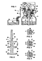
FIGURE 1 is a cross sectional view through components of a water softener that incorporates a valve piston according to the present invention; -
FIGURE 2 is a cross sectional view through the valve piston; and -
FIGURES 3-5 are enlarged views of three embodiments of seals integrated into the valve piston. - Referring initially to
Figure 1 , awater softener 10 includes atreatment tank 12 which contains abed 14 of ion exchange resin particles. Acontrol valve 16 is fixed to the top of thetreatment tank 12. In the service mode, hard water to be softened is supplied to aninlet passage 18 from which water flows toinlets 20 at the top of the treatment tank and then flows through the resin bed to absorb minerals from the water. Anoutlet conduit 22 extends through thebed 14 from a point adjacent the bottom of thetreatment tank 12 to anoutlet passage 24 in thecontrol valve 16. Water that has been treated in theresin bed 14 flows through the outlet conduit 22 into the valve'soutlet passage 24 from which the water exits the water softener 10 into the pipes in a building. - The
resin bed 14 eventually becomes exhausted and no longer is capable of softening the water. Either periodically in response to a timer or in response to sensors detecting depletion of the resin bed, a controller 26 initiates a standard regeneration process. The controller 26 is fixed to the top of the valve and has amotor 28 that is adapted to drive avalve piston 30 within acircular bore 15 of thecontrol valve 16 through a slowly moving and uninterrupted reciprocating cycle. As thepiston 30 moves, the passages of thecontrol valve 16 are connected in several combinations to direct water through different paths for the various stages of the regeneration process. - A typical resin bed regeneration process commences with a backwash step in which hard water is directed from the control valve into the
outlet conduit 22 and upwards through theresin bed 14 finally exiting the water softener via a drain passage (not shown). The backwash step is followed by a brining step. Thecontrol valve 16 has aninjector 32 that is connected by aconduit 34 through a shut-offvalve 36 and atube 38 to abrine tank 40. Thebrine tank 40 contains abrine solution 42 of a common salt, such as a sodium chloride or potassium chloride. In this stage of generation, a partial vacuum created by the flow of hard water through theinjector 32 withdraws brine from thebrine tank 40 through conduits 29 and 27 and into thetreatment tank 12. The concentrated brine solution replaces the di-positive and tri-positive ions in theresin bed 14 with unipositive ions recharging the bed. When the contents of thebrine tank 40 have been exhausted, acheck valve 44 closes to prevent air from being injected into the system and water continues to flow through theinjector 32 free of brine. This water propels the brine solution from thetreatment tank 12 and then rinses thebed 14 to remove residual brine. - During the final stage of the regeneration process, the
brine tank 40 is refilled with water and thesoftener resin bed 14 is purged. This is accomplished by feeding water into thebrine tank 40 through the open shut-offvalve 36 and into thetreatment tank 12 through theinlets 20. Water passing through theresin bed 14 exits via the drain passage. Thereafter, thecontrol valve 16 is returned to the position that places thewater softener 10 into the previously described service mode in which the water for the building in treated. - With reference to
Figure 2 , thecontrol valve 16 has anovel piston 30 with a central portion, or shaft, 50 from which a plurality of circular disk-shapedflanges recesses like stem 56 extends axially from one end of thecentral portion 50 and is adapted for attaching to the mechanism of the controller 26, which moves thepiston 30 within thebore 15 of thecontrol valve 16 during the regeneration mode. Thecentral portion 50, flanges 51-53 and thestem 56 form a body piston (30) of thevalve piston 30 that preferably is fabricated of stainless steel or other corrosion resistant material. - Each
flange peripheral surface central portion 50 with an annular groove in that surface. Aseparate sealing ring peripheral surface recesses Figure 1 ). -
Figure 3 illustrates the cross section through the sealingring 61 located in the groove 66 in theperipheral surface 57 of one of theflanges 51. The annular groove 66 has a dove tail cross section that is undercut so that the interior surface is wider than the opening of the groove through theperipheral surface 58 of theflange 52. The undercut captivates the sealingring 61 within the annular groove 66 and prevents the sealing ring from being pulled out of that groove by forces produced by water flowing through the assembledcontrol valve 16. This is a design requirement because as thepiston 30 moves within thebore 15 opening and closing paths through the control valve, water rushes past theperipheral surfaces 57 of the piston flanges creating forces that tend to dislodge the sealing rings. -
Figure 4 illustrates a second style of sealingring 70 located in agroove 72 in theperipheral surface 58 of one of theflanges 52. Thegroove 72 has T-shaped cross section in which aninner region 74 has a width that is larger than the width of the groove in anouter region 76 at theperipheral surface 58 of the flange. The sealingring 70 is enlarged in thatinner region 74, thereby captivating the sealing ring in thegroove 72. This style of sealingring 70 has a pair oflobes 78 which engage the interior surface of the valve bore 15. - A third style of sealing
ring 80 is shown inFigure 5 located in an identicalannular groove 72 in one of theflanges 52. This style of sealingring 80 has threelobes 82 which engage the interior surface of the valve bore 15. - The
valve piston 30 is fabricated by first producing thebody 60 using an investment casting process, such as lost wax casting. The mold for this casting process includes material, such as wax, which defines the grooves in the outer circumferentially peripheral surfaces of the flanges 51-53. Because this material can be easily removed after the material of thebody 60 has hardened, the grooves can be undercut to provide a groove in which the sealing rings are locked in place, as described previously. After thevalve body 60 has hardened, it is placed in a second mold for forming the sealing rings 61-63. This second mold has a cavity in which thebody 60 of thevalve piston 30 fits leaving small voids around each flange, which then are filled with the material for the sealing rings which flows into the entire groove 57-59 in the respective flange 51-53. After the sealing rings have hardened, the second mold is opened and the completedvalve piston 30 is removed. - By over molding the sealing rings 61-63 into the grooves of the metal portion of the
piston 30, the sealing rings become locked within the grooves and are not easily removed, such as due to the force from the water flowing through the assembledcontrol valve 16. If non-locking type grooves were used with resilient sealing rings merely stretched around the flanges 51-56 and then released into the grooves, the sealing rings might not be held in place securely enough to resist the water flow force that tends to dislodge the sealing rings. - The foregoing description was primarily directed to a preferred embodiment of the invention. Although some attention was given to various alternatives within the scope of the invention, it is anticipated that one skilled in the art will likely realize additional alternatives that are now apparent from disclosure of embodiments of the invention. Accordingly, the scope of the invention should be determined from the following claims and not limited by the above disclosure.
Claims (14)
- A piston (30) for a control valve (16) of a water treatment apparatus, the piston (30) comprising:a body (60) having a central portion (50) from which at least one flange (51; 52; 53) projects radially outward, each flange (51; 52; 53) has a peripheral surface (57; 58; 59) extending around the central portion (50) with an annular groove (66; 72) therein, the annular groove (66; 72) has a width that increases from the peripheral surface (57; 58; 59) radially inward into the flange (51; 52; 53); anda separate sealing ring (61; 62; 63) within the annular groove (66; 72) of each flange (51; 52; 53) and is captivated therein by increasing width of the groove (66; 72).
- The piston (30) as recited in claim 1, wherein each sealing ring (61; 62; 63) is fabricated of a resilient material.
- The piston (30) as recited in claim 1 or claim 2, wherein the body (60) is fabricated by an investment casting process.
- The piston (30) as recited in any one of the preceding claims,
wherein each sealing ring (61; 62; 63) is molded into annular groove (66; 72) in the body (60). - The piston (30) as recited in any one of the preceding claims,
wherein at least one groove (66; 72) has a dove tail cross section. - The piston (30) as recited in any one of claims 1 to 4, wherein at least one groove (66; 72) has a T-shaped cross section.
- The piston (30) as recited in any one of claims 1 to 4 or 6, wherein at least one sealing ring (61; 62; 63) has a plurality of lobes projecting away from the flange (66; 72).
- The piston (30) as recited in any one of the preceding claims,
wherein at least one sealing ring (61; 62; 63) has a curved surface extending outward from the flange (66; 72). - The piston (30) as recited in any one of the preceding claims,
wherein each sealing ring (61; 62; 63) is formed by molded rubber. - A method for producing a piston (30) for a control valve (16) of a water treatment apparatus (10), the method comprising:fabricating a body (60) of the piston (30) which has a central portion (50) from which at least one flange (51; 52; 53) projects radially outward, each flange (51; 52; 53) having an outer surface (57; 58; 59) extending around the central portion (50) with an annular groove (66; 72), the annular groove (66; 72) has a width that increases from the outer surface (57; 58; 59) radially inward into the flange (51; 52; 53); andmolding a separate sealing ring (61; 62; 63) into the annular groove (66; 72) of each flange (51; 52; 53) so that the sealing ring (61; 62; 63) is captivated on the body (60) by the increasing width of the groove (66; 72).
- The method as recited in claim 10, wherein the body (60) is fabricated by investment casting wherein each groove (66; 72) is formed by lost material.
- The method as recited in claim 10 or claim 11, wherein the body (60) is fabricated of stainless steel.
- The method as recited in any one of claims 10 to 12, wherein each sealing ring (61; 62; 63) is formed by molded rubber.
- The method as recited in any one of claims 10 to 13, wherein each sealing ring (61; 62; 63) is formed of a resilient plastic.
Applications Claiming Priority (2)
| Application Number | Priority Date | Filing Date | Title |
|---|---|---|---|
| US11/041,449 US8141848B2 (en) | 2005-01-24 | 2005-01-24 | Piston with integral seals for a water softener control valve |
| EP20060718837 EP1844253B1 (en) | 2005-01-24 | 2006-01-19 | Piston with integral seals for a water softener control valve |
Related Parent Applications (4)
| Application Number | Title | Priority Date | Filing Date |
|---|---|---|---|
| EP20060718837 Division EP1844253B1 (en) | 2005-01-24 | 2006-01-19 | Piston with integral seals for a water softener control valve |
| WOPCT/US2006/001828 Previously-Filed-Application | 2006-01-19 | ||
| PCT/US2006/001828 Previously-Filed-Application WO2006081121A1 (en) | 2005-01-24 | 2006-01-19 | Piston with integral seals for a water softener control valve |
| EP06718837.5 Division | 2006-01-19 |
Publications (2)
| Publication Number | Publication Date |
|---|---|
| EP2500607A1 true EP2500607A1 (en) | 2012-09-19 |
| EP2500607B1 EP2500607B1 (en) | 2014-02-19 |
Family
ID=36581843
Family Applications (2)
| Application Number | Title | Priority Date | Filing Date |
|---|---|---|---|
| EP20120152361 Expired - Lifetime EP2500607B1 (en) | 2005-01-24 | 2006-01-19 | Piston with integral seals for a water softener control valve |
| EP20060718837 Expired - Lifetime EP1844253B1 (en) | 2005-01-24 | 2006-01-19 | Piston with integral seals for a water softener control valve |
Family Applications After (1)
| Application Number | Title | Priority Date | Filing Date |
|---|---|---|---|
| EP20060718837 Expired - Lifetime EP1844253B1 (en) | 2005-01-24 | 2006-01-19 | Piston with integral seals for a water softener control valve |
Country Status (7)
| Country | Link |
|---|---|
| US (1) | US8141848B2 (en) |
| EP (2) | EP2500607B1 (en) |
| JP (2) | JP5047810B2 (en) |
| CN (1) | CN101124421A (en) |
| CA (1) | CA2594664A1 (en) |
| ES (2) | ES2398129T3 (en) |
| WO (1) | WO2006081121A1 (en) |
Families Citing this family (11)
| Publication number | Priority date | Publication date | Assignee | Title |
|---|---|---|---|---|
| US8141848B2 (en) * | 2005-01-24 | 2012-03-27 | Pentair Residential Filtration, Llc | Piston with integral seals for a water softener control valve |
| US20130292594A1 (en) * | 2012-05-01 | 2013-11-07 | Hamilton Sundstrand Corporation | Wear combination for starter air valve |
| US20160114767A1 (en) * | 2014-10-22 | 2016-04-28 | Umm Al-Qura University | Liquid dispensing apparatus |
| CN104455552B (en) * | 2014-12-09 | 2018-02-16 | 温州市润新机械制造有限公司 | A kind of water treatment control valve |
| US10612670B2 (en) | 2015-10-23 | 2020-04-07 | Culligan International Company | Control valve for fluid treatment apparatus |
| KR102712621B1 (en) * | 2015-11-11 | 2024-10-04 | 그린, 트위드 테크놀로지스, 인코포레이티드 | Sealing rings and sealing assembly for high temperature end applications |
| US10233093B2 (en) | 2016-03-14 | 2019-03-19 | Pentair Residential Filtration, Llc | Shuttle valve for water softener system and method |
| DE102016220857B4 (en) * | 2016-10-24 | 2019-12-12 | Festo Ag & Co. Kg | Valve slide and valve equipped with it |
| DE102016220855B4 (en) * | 2016-10-24 | 2019-12-12 | Festo Ag & Co. Kg | Valve slide and valve equipped with it |
| CN110220012B (en) * | 2019-06-19 | 2024-01-12 | 南京福碧源环境技术有限公司 | Full-closed soft water control valve |
| CN116529511A (en) * | 2020-10-30 | 2023-08-01 | 罗特克斯自动化有限公司 | Pneumatic valve with flexible seal |
Citations (5)
| Publication number | Priority date | Publication date | Assignee | Title |
|---|---|---|---|---|
| US3909017A (en) * | 1972-12-06 | 1975-09-30 | Mecman Ab | Sealing device |
| US4892287A (en) * | 1987-09-18 | 1990-01-09 | Mokveld Valves B.V. | Valve body with a housing having a cylindrical flow passage |
| DE29507257U1 (en) * | 1994-05-02 | 1995-07-13 | Hafner, Erik, Dipl.-Ing. (HTL), Halászi | Sliding seal in a pneumatic multi-position valve |
| US5513674A (en) * | 1993-05-05 | 1996-05-07 | Hoerbiger Ventilwerke Aktiengesellschaft | Sealing arrangement |
| DE19619999A1 (en) * | 1996-05-17 | 1997-11-20 | Reinz Dichtungs Gmbh | Forming of a sealing lip on a seal body |
Family Cites Families (23)
| Publication number | Priority date | Publication date | Assignee | Title |
|---|---|---|---|---|
| US2585556A (en) * | 1947-03-19 | 1952-02-12 | Ohio Brass Co | Reciprocating valve |
| US2908480A (en) * | 1955-01-31 | 1959-10-13 | Chiksan Co | Pressure relieved valve seal |
| US2886284A (en) * | 1955-09-13 | 1959-05-12 | Wheatley Charles | Flanged sealing ring |
| US2841429A (en) * | 1955-10-04 | 1958-07-01 | Parker Hannifin Corp | Sealing ring and joint |
| US3049239A (en) * | 1958-03-17 | 1962-08-14 | Bruner Corp | Fluid flow control system |
| US3215441A (en) * | 1962-05-17 | 1965-11-02 | Prec Associates Inc | Resilient seal and distortion controlling means therefor |
| US3426799A (en) * | 1964-10-07 | 1969-02-11 | Kinwell Dev Co | Automatic valve |
| US3612483A (en) * | 1968-04-12 | 1971-10-12 | Rockwell Mfg Co | Valves with deformable sealing |
| US3575431A (en) * | 1968-08-19 | 1971-04-20 | Grove Valve & Regulator Co | Seal assembly |
| US3630485A (en) * | 1970-05-25 | 1971-12-28 | Crane Co | Butterfly valve seat |
| US3968971A (en) * | 1973-05-22 | 1976-07-13 | Automatisation - Sogemo | Fluid-tight packing |
| US3929161A (en) * | 1973-08-22 | 1975-12-30 | Uni Mist | Spool valve for multiple adjustable systems |
| US3874412A (en) | 1974-04-29 | 1975-04-01 | Fleckenstein A J | Timing motor drive mechanism for water softener valves |
| US4345739A (en) * | 1980-08-07 | 1982-08-24 | Barton Valve Company | Flanged sealing ring |
| US4522374A (en) * | 1983-03-03 | 1985-06-11 | Mac Valves, Inc. | Valve spool |
| JPH056452Y2 (en) * | 1988-02-29 | 1993-02-18 | ||
| US5250187A (en) | 1989-02-08 | 1993-10-05 | Autotrol Corporation | Resin bed for liquid treatment |
| DE4101059A1 (en) * | 1991-01-16 | 1992-07-23 | Festo Kg | SEALING DEVICE FOR A MULTI-WAY VALVE AND METHOD FOR THEIR PRODUCTION |
| JPH0721276Y2 (en) * | 1992-07-13 | 1995-05-17 | 三浦工業株式会社 | Drain discharge line of water softener |
| US5609343A (en) * | 1994-10-14 | 1997-03-11 | Smc Corporation | Sealing rings for spool valves |
| EP0882193A4 (en) | 1996-01-26 | 2000-12-06 | Autotrol Corp | Adaptable control valve for fluid treatment system |
| US6402944B1 (en) * | 2000-09-21 | 2002-06-11 | Clack Corporation | Water softener control valve with removable seal stack |
| US8141848B2 (en) * | 2005-01-24 | 2012-03-27 | Pentair Residential Filtration, Llc | Piston with integral seals for a water softener control valve |
-
2005
- 2005-01-24 US US11/041,449 patent/US8141848B2/en not_active Expired - Fee Related
-
2006
- 2006-01-19 EP EP20120152361 patent/EP2500607B1/en not_active Expired - Lifetime
- 2006-01-19 EP EP20060718837 patent/EP1844253B1/en not_active Expired - Lifetime
- 2006-01-19 CA CA 2594664 patent/CA2594664A1/en not_active Abandoned
- 2006-01-19 CN CNA2006800029982A patent/CN101124421A/en active Pending
- 2006-01-19 WO PCT/US2006/001828 patent/WO2006081121A1/en not_active Ceased
- 2006-01-19 ES ES06718837T patent/ES2398129T3/en not_active Expired - Lifetime
- 2006-01-19 ES ES12152361.7T patent/ES2470415T3/en not_active Expired - Lifetime
- 2006-01-19 JP JP2007552251A patent/JP5047810B2/en not_active Expired - Fee Related
-
2012
- 2012-05-28 JP JP2012121051A patent/JP2012206117A/en active Pending
Patent Citations (5)
| Publication number | Priority date | Publication date | Assignee | Title |
|---|---|---|---|---|
| US3909017A (en) * | 1972-12-06 | 1975-09-30 | Mecman Ab | Sealing device |
| US4892287A (en) * | 1987-09-18 | 1990-01-09 | Mokveld Valves B.V. | Valve body with a housing having a cylindrical flow passage |
| US5513674A (en) * | 1993-05-05 | 1996-05-07 | Hoerbiger Ventilwerke Aktiengesellschaft | Sealing arrangement |
| DE29507257U1 (en) * | 1994-05-02 | 1995-07-13 | Hafner, Erik, Dipl.-Ing. (HTL), Halászi | Sliding seal in a pneumatic multi-position valve |
| DE19619999A1 (en) * | 1996-05-17 | 1997-11-20 | Reinz Dichtungs Gmbh | Forming of a sealing lip on a seal body |
Also Published As
| Publication number | Publication date |
|---|---|
| JP2012206117A (en) | 2012-10-25 |
| CN101124421A (en) | 2008-02-13 |
| EP2500607B1 (en) | 2014-02-19 |
| US20060162790A1 (en) | 2006-07-27 |
| WO2006081121A1 (en) | 2006-08-03 |
| ES2470415T3 (en) | 2014-06-23 |
| EP1844253B1 (en) | 2012-08-08 |
| CA2594664A1 (en) | 2006-08-03 |
| EP1844253A1 (en) | 2007-10-17 |
| JP5047810B2 (en) | 2012-10-10 |
| ES2398129T3 (en) | 2013-03-13 |
| US8141848B2 (en) | 2012-03-27 |
| JP2008528254A (en) | 2008-07-31 |
Similar Documents
| Publication | Publication Date | Title |
|---|---|---|
| JP2012206117A (en) | Piston with integral seals for water softener control valve | |
| US20060086648A1 (en) | Conductivity sensor for an ion exchange water softener | |
| CN105753105A (en) | Polluting and plugging cause analysis and determination method for reverse osmosis system in reuse process of circulating water effluent of power plant and chemical cleaning method | |
| CN105728065B (en) | The regeneration method of softener resin | |
| JP2005313162A (en) | Water softener | |
| US3073341A (en) | Water softener control | |
| CN108911036A (en) | A kind of near-zero release softened water equipment and method | |
| US7610933B2 (en) | Two part valve body for a water treatment system | |
| US7004200B1 (en) | Constant flow valve for a water softener control assembly | |
| JP2867906B2 (en) | Water softener | |
| US20070001406A1 (en) | Press in place seal for a water softener control valve | |
| CN101898811A (en) | Reclaimed water manufacturing device and manufacturing method | |
| KR101595571B1 (en) | Gravity type water softener having auto revival function and auto revival method for the same | |
| JPH11347426A (en) | Method for controlling water softener | |
| US3467022A (en) | Aspirator control apparatus | |
| US20020166817A1 (en) | Ion exchange media regeneration method for fluid treatment | |
| US7297264B2 (en) | Apparatus and method of water treatment with preliminary screen | |
| JP5084279B2 (en) | How to replace the entire amount of ion exchange resin | |
| KR100433999B1 (en) | Head assembly for water softener and water softener using the same | |
| JP2008023476A (en) | Tap water softener | |
| KR100554657B1 (en) | Water softener | |
| JPH10216537A (en) | Water softening apparatus | |
| JP2014083533A (en) | Water softener |
Legal Events
| Date | Code | Title | Description |
|---|---|---|---|
| PUAI | Public reference made under article 153(3) epc to a published international application that has entered the european phase |
Free format text: ORIGINAL CODE: 0009012 |
|
| AC | Divisional application: reference to earlier application |
Ref document number: 1844253 Country of ref document: EP Kind code of ref document: P |
|
| AK | Designated contracting states |
Kind code of ref document: A1 Designated state(s): AT BE BG CH CY CZ DE DK EE ES FI FR GB GR HU IE IS IT LI LT LU LV MC NL PL PT RO SE SI SK TR |
|
| 17P | Request for examination filed |
Effective date: 20130307 |
|
| 17Q | First examination report despatched |
Effective date: 20130502 |
|
| GRAP | Despatch of communication of intention to grant a patent |
Free format text: ORIGINAL CODE: EPIDOSNIGR1 |
|
| INTG | Intention to grant announced |
Effective date: 20130815 |
|
| GRAS | Grant fee paid |
Free format text: ORIGINAL CODE: EPIDOSNIGR3 |
|
| GRAA | (expected) grant |
Free format text: ORIGINAL CODE: 0009210 |
|
| AC | Divisional application: reference to earlier application |
Ref document number: 1844253 Country of ref document: EP Kind code of ref document: P |
|
| AK | Designated contracting states |
Kind code of ref document: B1 Designated state(s): AT BE BG CH CY CZ DE DK EE ES FI FR GB GR HU IE IS IT LI LT LU LV MC NL PL PT RO SE SI SK TR |
|
| REG | Reference to a national code |
Ref country code: GB Ref legal event code: FG4D |
|
| REG | Reference to a national code |
Ref country code: CH Ref legal event code: EP |
|
| REG | Reference to a national code |
Ref country code: AT Ref legal event code: REF Ref document number: 652874 Country of ref document: AT Kind code of ref document: T Effective date: 20140315 |
|
| REG | Reference to a national code |
Ref country code: DE Ref legal event code: R096 Ref document number: 602006040356 Country of ref document: DE Effective date: 20140403 |
|
| REG | Reference to a national code |
Ref country code: IE Ref legal event code: FG4D |
|
| REG | Reference to a national code |
Ref country code: ES Ref legal event code: FG2A Ref document number: 2470415 Country of ref document: ES Kind code of ref document: T3 Effective date: 20140623 |
|
| REG | Reference to a national code |
Ref country code: NL Ref legal event code: VDEP Effective date: 20140219 |
|
| REG | Reference to a national code |
Ref country code: AT Ref legal event code: MK05 Ref document number: 652874 Country of ref document: AT Kind code of ref document: T Effective date: 20140219 |
|
| RAP2 | Party data changed (patent owner data changed or rights of a patent transferred) |
Owner name: PENTAIR RESIDENTIAL FILTRATION, LLC |
|
| REG | Reference to a national code |
Ref country code: LT Ref legal event code: MG4D |
|
| PG25 | Lapsed in a contracting state [announced via postgrant information from national office to epo] |
Ref country code: IS Free format text: LAPSE BECAUSE OF FAILURE TO SUBMIT A TRANSLATION OF THE DESCRIPTION OR TO PAY THE FEE WITHIN THE PRESCRIBED TIME-LIMIT Effective date: 20140619 Ref country code: LT Free format text: LAPSE BECAUSE OF FAILURE TO SUBMIT A TRANSLATION OF THE DESCRIPTION OR TO PAY THE FEE WITHIN THE PRESCRIBED TIME-LIMIT Effective date: 20140219 |
|
| PG25 | Lapsed in a contracting state [announced via postgrant information from national office to epo] |
Ref country code: NL Free format text: LAPSE BECAUSE OF FAILURE TO SUBMIT A TRANSLATION OF THE DESCRIPTION OR TO PAY THE FEE WITHIN THE PRESCRIBED TIME-LIMIT Effective date: 20140219 Ref country code: AT Free format text: LAPSE BECAUSE OF FAILURE TO SUBMIT A TRANSLATION OF THE DESCRIPTION OR TO PAY THE FEE WITHIN THE PRESCRIBED TIME-LIMIT Effective date: 20140219 Ref country code: SE Free format text: LAPSE BECAUSE OF FAILURE TO SUBMIT A TRANSLATION OF THE DESCRIPTION OR TO PAY THE FEE WITHIN THE PRESCRIBED TIME-LIMIT Effective date: 20140219 Ref country code: CY Free format text: LAPSE BECAUSE OF FAILURE TO SUBMIT A TRANSLATION OF THE DESCRIPTION OR TO PAY THE FEE WITHIN THE PRESCRIBED TIME-LIMIT Effective date: 20140219 Ref country code: FI Free format text: LAPSE BECAUSE OF FAILURE TO SUBMIT A TRANSLATION OF THE DESCRIPTION OR TO PAY THE FEE WITHIN THE PRESCRIBED TIME-LIMIT Effective date: 20140219 Ref country code: PT Free format text: LAPSE BECAUSE OF FAILURE TO SUBMIT A TRANSLATION OF THE DESCRIPTION OR TO PAY THE FEE WITHIN THE PRESCRIBED TIME-LIMIT Effective date: 20140619 |
|
| PG25 | Lapsed in a contracting state [announced via postgrant information from national office to epo] |
Ref country code: LV Free format text: LAPSE BECAUSE OF FAILURE TO SUBMIT A TRANSLATION OF THE DESCRIPTION OR TO PAY THE FEE WITHIN THE PRESCRIBED TIME-LIMIT Effective date: 20140219 |
|
| PG25 | Lapsed in a contracting state [announced via postgrant information from national office to epo] |
Ref country code: DK Free format text: LAPSE BECAUSE OF FAILURE TO SUBMIT A TRANSLATION OF THE DESCRIPTION OR TO PAY THE FEE WITHIN THE PRESCRIBED TIME-LIMIT Effective date: 20140219 Ref country code: RO Free format text: LAPSE BECAUSE OF FAILURE TO SUBMIT A TRANSLATION OF THE DESCRIPTION OR TO PAY THE FEE WITHIN THE PRESCRIBED TIME-LIMIT Effective date: 20140219 Ref country code: CZ Free format text: LAPSE BECAUSE OF FAILURE TO SUBMIT A TRANSLATION OF THE DESCRIPTION OR TO PAY THE FEE WITHIN THE PRESCRIBED TIME-LIMIT Effective date: 20140219 Ref country code: EE Free format text: LAPSE BECAUSE OF FAILURE TO SUBMIT A TRANSLATION OF THE DESCRIPTION OR TO PAY THE FEE WITHIN THE PRESCRIBED TIME-LIMIT Effective date: 20140219 |
|
| REG | Reference to a national code |
Ref country code: DE Ref legal event code: R097 Ref document number: 602006040356 Country of ref document: DE |
|
| PG25 | Lapsed in a contracting state [announced via postgrant information from national office to epo] |
Ref country code: SK Free format text: LAPSE BECAUSE OF FAILURE TO SUBMIT A TRANSLATION OF THE DESCRIPTION OR TO PAY THE FEE WITHIN THE PRESCRIBED TIME-LIMIT Effective date: 20140219 Ref country code: PL Free format text: LAPSE BECAUSE OF FAILURE TO SUBMIT A TRANSLATION OF THE DESCRIPTION OR TO PAY THE FEE WITHIN THE PRESCRIBED TIME-LIMIT Effective date: 20140219 |
|
| PLBE | No opposition filed within time limit |
Free format text: ORIGINAL CODE: 0009261 |
|
| STAA | Information on the status of an ep patent application or granted ep patent |
Free format text: STATUS: NO OPPOSITION FILED WITHIN TIME LIMIT |
|
| REG | Reference to a national code |
Ref country code: FR Ref legal event code: PLFP Year of fee payment: 10 |
|
| 26N | No opposition filed |
Effective date: 20141120 |
|
| REG | Reference to a national code |
Ref country code: DE Ref legal event code: R097 Ref document number: 602006040356 Country of ref document: DE Effective date: 20141120 |
|
| REG | Reference to a national code |
Ref country code: DE Ref legal event code: R081 Ref document number: 602006040356 Country of ref document: DE Owner name: PENTAIR RESIDENTIAL FILTRATION, LLC, GOLDEN VA, US Free format text: FORMER OWNER: GENERAL ELECTRIC CO., SCHENECTADY, N.Y., US Effective date: 20150218 |
|
| PGFP | Annual fee paid to national office [announced via postgrant information from national office to epo] |
Ref country code: ES Payment date: 20150115 Year of fee payment: 10 Ref country code: IT Payment date: 20150128 Year of fee payment: 10 Ref country code: DE Payment date: 20150121 Year of fee payment: 10 |
|
| PG25 | Lapsed in a contracting state [announced via postgrant information from national office to epo] |
Ref country code: SI Free format text: LAPSE BECAUSE OF FAILURE TO SUBMIT A TRANSLATION OF THE DESCRIPTION OR TO PAY THE FEE WITHIN THE PRESCRIBED TIME-LIMIT Effective date: 20140219 |
|
| PGFP | Annual fee paid to national office [announced via postgrant information from national office to epo] |
Ref country code: FR Payment date: 20150122 Year of fee payment: 10 Ref country code: GB Payment date: 20150121 Year of fee payment: 10 |
|
| PGFP | Annual fee paid to national office [announced via postgrant information from national office to epo] |
Ref country code: BE Payment date: 20150121 Year of fee payment: 10 |
|
| REG | Reference to a national code |
Ref country code: GB Ref legal event code: 732E Free format text: REGISTERED BETWEEN 20150618 AND 20150624 |
|
| REG | Reference to a national code |
Ref country code: CH Ref legal event code: PL |
|
| PG25 | Lapsed in a contracting state [announced via postgrant information from national office to epo] |
Ref country code: LU Free format text: LAPSE BECAUSE OF FAILURE TO SUBMIT A TRANSLATION OF THE DESCRIPTION OR TO PAY THE FEE WITHIN THE PRESCRIBED TIME-LIMIT Effective date: 20150119 |
|
| PG25 | Lapsed in a contracting state [announced via postgrant information from national office to epo] |
Ref country code: MC Free format text: LAPSE BECAUSE OF FAILURE TO SUBMIT A TRANSLATION OF THE DESCRIPTION OR TO PAY THE FEE WITHIN THE PRESCRIBED TIME-LIMIT Effective date: 20140219 |
|
| PG25 | Lapsed in a contracting state [announced via postgrant information from national office to epo] |
Ref country code: CH Free format text: LAPSE BECAUSE OF NON-PAYMENT OF DUE FEES Effective date: 20150131 Ref country code: LI Free format text: LAPSE BECAUSE OF NON-PAYMENT OF DUE FEES Effective date: 20150131 |
|
| REG | Reference to a national code |
Ref country code: IE Ref legal event code: MM4A |
|
| PG25 | Lapsed in a contracting state [announced via postgrant information from national office to epo] |
Ref country code: IE Free format text: LAPSE BECAUSE OF NON-PAYMENT OF DUE FEES Effective date: 20150119 |
|
| PG25 | Lapsed in a contracting state [announced via postgrant information from national office to epo] |
Ref country code: BE Free format text: LAPSE BECAUSE OF NON-PAYMENT OF DUE FEES Effective date: 20160131 |
|
| PG25 | Lapsed in a contracting state [announced via postgrant information from national office to epo] |
Ref country code: GR Free format text: LAPSE BECAUSE OF FAILURE TO SUBMIT A TRANSLATION OF THE DESCRIPTION OR TO PAY THE FEE WITHIN THE PRESCRIBED TIME-LIMIT Effective date: 20140520 |
|
| REG | Reference to a national code |
Ref country code: DE Ref legal event code: R119 Ref document number: 602006040356 Country of ref document: DE |
|
| GBPC | Gb: european patent ceased through non-payment of renewal fee |
Effective date: 20160119 |
|
| REG | Reference to a national code |
Ref country code: FR Ref legal event code: ST Effective date: 20160930 |
|
| PG25 | Lapsed in a contracting state [announced via postgrant information from national office to epo] |
Ref country code: GB Free format text: LAPSE BECAUSE OF NON-PAYMENT OF DUE FEES Effective date: 20160119 Ref country code: DE Free format text: LAPSE BECAUSE OF NON-PAYMENT OF DUE FEES Effective date: 20160802 |
|
| PG25 | Lapsed in a contracting state [announced via postgrant information from national office to epo] |
Ref country code: FR Free format text: LAPSE BECAUSE OF NON-PAYMENT OF DUE FEES Effective date: 20160201 |
|
| PG25 | Lapsed in a contracting state [announced via postgrant information from national office to epo] |
Ref country code: IT Free format text: LAPSE BECAUSE OF NON-PAYMENT OF DUE FEES Effective date: 20160119 |
|
| PG25 | Lapsed in a contracting state [announced via postgrant information from national office to epo] |
Ref country code: HU Free format text: LAPSE BECAUSE OF FAILURE TO SUBMIT A TRANSLATION OF THE DESCRIPTION OR TO PAY THE FEE WITHIN THE PRESCRIBED TIME-LIMIT; INVALID AB INITIO Effective date: 20060119 Ref country code: BG Free format text: LAPSE BECAUSE OF FAILURE TO SUBMIT A TRANSLATION OF THE DESCRIPTION OR TO PAY THE FEE WITHIN THE PRESCRIBED TIME-LIMIT Effective date: 20140219 |
|
| PG25 | Lapsed in a contracting state [announced via postgrant information from national office to epo] |
Ref country code: TR Free format text: LAPSE BECAUSE OF FAILURE TO SUBMIT A TRANSLATION OF THE DESCRIPTION OR TO PAY THE FEE WITHIN THE PRESCRIBED TIME-LIMIT Effective date: 20140219 |
|
| PG25 | Lapsed in a contracting state [announced via postgrant information from national office to epo] |
Ref country code: ES Free format text: LAPSE BECAUSE OF NON-PAYMENT OF DUE FEES Effective date: 20160120 |
|
| REG | Reference to a national code |
Ref country code: ES Ref legal event code: FD2A Effective date: 20181207 |