EP2500244A1 - Support system of a lateral aerodynamic panel of an aerodynamic kit of a cabin of an industrial vehicle - Google Patents
Support system of a lateral aerodynamic panel of an aerodynamic kit of a cabin of an industrial vehicle Download PDFInfo
- Publication number
- EP2500244A1 EP2500244A1 EP11158410A EP11158410A EP2500244A1 EP 2500244 A1 EP2500244 A1 EP 2500244A1 EP 11158410 A EP11158410 A EP 11158410A EP 11158410 A EP11158410 A EP 11158410A EP 2500244 A1 EP2500244 A1 EP 2500244A1
- Authority
- EP
- European Patent Office
- Prior art keywords
- cabin
- aerodynamic
- hinges
- panel
- support system
- Prior art date
- Legal status (The legal status is an assumption and is not a legal conclusion. Google has not performed a legal analysis and makes no representation as to the accuracy of the status listed.)
- Granted
Links
Images



Classifications
-
- B—PERFORMING OPERATIONS; TRANSPORTING
- B62—LAND VEHICLES FOR TRAVELLING OTHERWISE THAN ON RAILS
- B62D—MOTOR VEHICLES; TRAILERS
- B62D35/00—Vehicle bodies characterised by streamlining
- B62D35/001—For commercial vehicles or tractor-trailer combinations, e.g. caravans
Definitions
- the present invention refers to a support system of a lateral aerodynamic panel of an aerodynamic kit of a cabin of an industrial vehicle.
- Industrial vehicles above all those having a tractor and a semitrailer, usually comprise an aerodynamic kit associated to the cabin, whose aim is to reduce vehicle's wind resistance. Since the cabin defines a lower front surface with respect to the semitrailer, a spoiler is placed on the roof of the cabin in order to suitably connect the front surfaces of the two vehicle's portions and a pair of aerodynamic panels are laterally arranged between the cabin and the semitrailer, in order to obtain a continuous aerodynamic surface between the cabin and the semitrailer.
- Such lateral panels are fixed to the cabin.
- one panel is fixed, while the other may at least partially oscillate, so that the driver can easily reach the devices placed behind the cabin when the semitrailer is attached to the tractor.
- the aerodynamic panel opens towards the outside of the vehicle, while according to another solution the panel can be closed inside the vehicle, by folding over the rear surface of the cabin.
- Having a fixed portion of the panel implies that the width of the driver's access to the rear part of the cabin is reduced, when the semitrailer is attached to the tractor.
- the aim of the present invention is to overcome all the drawbacks set forth above and to provide a support system of a lateral aerodynamic panel of an aerodynamic kit of a cabin of an industrial vehicle suitable to adapt to any rear profile of the cabin, so that it can be monolithic and it can fully clear the lateral access to the rear part of the cabin when the semitrailer is attached to the tractor.
- the object of the present invention is a support system of a lateral aerodynamic panel of an aerodynamic kit of a cabin of an industrial vehicle suitable to adapt to any rear profile of the cabin, according to claim 1.
- the object of the present invention is in particular a lateral aerodynamic panel of an aerodynamic kit of a cabin of an industrial vehicle, comprising said support system suitable to adapt to any rear profile of the cabin, as described more fully in the claims which are an integral part of the present description.
- the present invention comprises an aerodynamic panel 1, having a vertical development, fixed to a cabin C of a vehicle by means of a support device comprising at least two parallelogram hinges 2 and 2', also called two-axis hinges.
- Each hinge comprises a fixing bracket 21 to the cabin C of the vehicle and a fixing bracket 22 to the aerodynamic panel 1.
- the two brackets 21 and 22 have a U-shaped cross section.
- Each bracket comprises two seats for the respective fixing pins of the ends of two connecting rods 23 and 24.
- each connecting rod 23 and 24 has a first end rotatably associated to the fixing bracket 21 and a second end rotatably associated to the fixing bracket 22.
- the connecting rod 24 is internal to the hinge's range of movement, since it is always comprised between the aerodynamic panel 1 and the connecting rod 23, which is thus external to the range.
- the connecting rods' axis of rotation are reciprocally parallel.
- the connecting rods are fixed in such a way that they cannot cross.
- the two connecting rods lie on the same opening plane as the hinge.
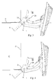
- Figure 1 shows the aerodynamic panel arranged in running conditions, namely aligned to the profile of the lateral wall of the vehicle cabin.
- the aerodynamic panel thanks to the two-axis hinges, moves away from such alignment with the lateral wall of the cabin C and ends its opening by overlapping on the lateral wall C1 of the cabin.
- the movement of the system and therefore the reciprocal positioning of the hinges is such that the opening/closing movement of the aerodynamic panel is substantially parallel to itself.
- hinge 2 is above the hinge 2', preferably plumb with respect to the latter.
- the face 1a of the panel always faces the outside, thus it is not necessary to take care of the appearance of the internal face 1b, moreover it is possible to completely remove the panel, thus completely clearing the lateral access to the devices of the rear part of the cabin when the semitrailer is attached to the tractor.
- the fixing bracket 21 of the upper hinge 2 may comprise an extension 8 and 9 respectively in order to adapt to the shape of the rear surface of the cabin.
- first stiffening rod 3 is connected by a first end to the connecting rod 24 comprised in the upper hinge 2 and by a second end to the connecting rod 24 comprised in the lower hinge 2', so that it is perpendicular to the opening planes of the hinges, which are reciprocally parallel.
- a second stiffening rod 4 is connected by a first end to the bracket 22 of the upper hinge 2 and by a second end to the bracket 22 of the lower hinge 2', so that it is substantially parallel to the vertical development of the aerodynamic panel 1.
- the panel may be made of any material, for example plastic, fiberglass, carbon fiber, etc.
- the stiffening rod 4 allows to anchor the panel to the support device not only in correspondence of the hinges, but also in an intermediate area between the hinges, since it is possible to exploit the second stiffening rod 4 that is parallel to the aerodynamic panel 1.
- at least a further interconnection between the aerodynamic panel 1 and the support system is possible.
- the support system in an alternative preferred embodiment, thus comprises at least two hinges and the interconnection rods 3 and 4 and at least a further interconnection element 10 that is intermediate between the two hinges 2 and 2' fixed to said stiffening rod 4.
- At least one of the two hinges comprises limit stops both for opening and for closing. Both are preferably adjustable.
- a first limit stop includes a pad 42, for example an elastomeric pad, fixed to the internal connected rod 24 by a screw, a nut and a lock nut, so that it projects with respect to the connecting rod and it abuts against the bracket 22, when the panel is in a position fully closed.
- a pad 42 for example an elastomeric pad
- the bracket 22 is provided with a tongue 32 suitable to abut against the pad 42.
- Another pad 26 is integral with the bracket 22, showed in figures 1 - 4 and 6 , and is intended to abut against the connecting rod 24 when the panel is in a fully open position.
- the pad may positioned either on a fixing bracket or on a connecting rod without distinction. It is evident that inverting the reciprocal position tongue/pad is completely equivalent, even though the configuration showed is preferable in terms of bulk.
- At least one of the two hinges comprises a closing lock of the aerodynamic panel, which prevents its opening when the vehicle is travelling.
- the lower hinge 2' with particular reference to figures 6 and 7 comprises a latch 5, enbloc with a handle 52, slidingly fixed to the fixing bracket 22 of the aerodynamic panel 1.
- the latch 5 is placed and may slide perpendicularly to the opening plane of the hinge.
- the internal connecting rod 24 has a slot 33 in correspondence of the coupling end 51 of the latch 5.
- the coupling end 51 of the latch 5 engages the slot 33 of the internal connecting rod 24, thus preventing the opening of the hinge.
- a return spring not showed in the figures, forces the latch to engage said slot.
- the handle 52 of the latch is dimensioned so that the driver can grab it by slipping a hand under the lower edge of the aerodynamic panel 1, so that he/she can pull it down in order to unlock the corresponding lower hinge 2'.
- the side of the coupling end 51 of the latch 5 that faces the slot 33 is rounded, when it is not engaged with it, and its opposite side is flat, while the internal connecting rod 24 comprises a guiding tongue 44 which cooperates with the rounding of the end 51 in order to induce the lowering of the latch during the locking of the aerodynamic panel 1. Then, when the end 51 reaches the slot 33, the return spring makes the latch raise and engage the slot 33.
- each connecting rod is realized by means of a pair of flat plates, parallel and distanced at the ends interconnecting with the brackets 21 and 22.
- the connecting rods are lighter, their strength being equal.
- a handle 6 is fixed between the fixing brackets 21 of the two hinges, the lower hinge 2' and the upper hinge 2.
- the driver can get hold of such handle 6 when he/she has to get on the vehicle to reach the devices placed in the back of the cabin.
- the present invention allows to reversibly and completely remove the lateral aerodynamic panels, even when the rear profile of the lateral wall of the vehicle cabin is not straight.
- Another advantage lies in that it has a rigid support structure, so that the aerodynamic panel is not subject to torsion stresses.
- a further advantage is that any adaptation to the cabin's shape can be carried out by means of the extensions 8 and 9 of the fixing brackets 21.
- Another advantage lies in that a holding handle is fixed to the support system and not directly to the cabin, limiting the number of holes and of assembling operations.
Landscapes
- Engineering & Computer Science (AREA)
- Chemical & Material Sciences (AREA)
- Combustion & Propulsion (AREA)
- Transportation (AREA)
- Mechanical Engineering (AREA)
- Body Structure For Vehicles (AREA)
Abstract
Description
- The present invention refers to a support system of a lateral aerodynamic panel of an aerodynamic kit of a cabin of an industrial vehicle.
- Industrial vehicles, above all those having a tractor and a semitrailer, usually comprise an aerodynamic kit associated to the cabin, whose aim is to reduce vehicle's wind resistance. Since the cabin defines a lower front surface with respect to the semitrailer, a spoiler is placed on the roof of the cabin in order to suitably connect the front surfaces of the two vehicle's portions and a pair of aerodynamic panels are laterally arranged between the cabin and the semitrailer, in order to obtain a continuous aerodynamic surface between the cabin and the semitrailer.
- Such lateral panels are fixed to the cabin.
- Usually, in order to simplify the assembling, one panel is fixed, while the other may at least partially oscillate, so that the driver can easily reach the devices placed behind the cabin when the semitrailer is attached to the tractor. According to a solution of the prior art, the aerodynamic panel opens towards the outside of the vehicle, while according to another solution the panel can be closed inside the vehicle, by folding over the rear surface of the cabin.
- Since the rear profile of the lateral wall of the vehicle cabin is not straight, the aerodynamic panel has to follow the profile of such surface, thus complicating the arrangement of the hinges that allow an easy opening or closing rotation of the panel. According to the prior art, such problem may be solved by arranging a portion of the panel that is fixed and integral with the cabin and follows the rear profile of the cabin, with another portion of the panel that can oscillate, so that they define a straight connection line between the fixed and the oscillating portion.
- Having a fixed portion of the panel implies that the width of the driver's access to the rear part of the cabin is reduced, when the semitrailer is attached to the tractor.
- Therefore the aim of the present invention is to overcome all the drawbacks set forth above and to provide a support system of a lateral aerodynamic panel of an aerodynamic kit of a cabin of an industrial vehicle suitable to adapt to any rear profile of the cabin, so that it can be monolithic and it can fully clear the lateral access to the rear part of the cabin when the semitrailer is attached to the tractor.
- The object of the present invention is a support system of a lateral aerodynamic panel of an aerodynamic kit of a cabin of an industrial vehicle suitable to adapt to any rear profile of the cabin, according to
claim 1. - The object of the present invention is in particular a lateral aerodynamic panel of an aerodynamic kit of a cabin of an industrial vehicle, comprising said support system suitable to adapt to any rear profile of the cabin, as described more fully in the claims which are an integral part of the present description.
- Further purposes and advantages of the present invention will become clear from the following detailed description of a preferred embodiment (and its alternative embodiments) and the drawings that are attached hereto, which are merely illustrative and non-limitative, in which:
- figures from 1 to 4 show an opening sequence of a lateral aerodynamic panel by means of respective support means according to a top view of a left panel, according to a front view of the vehicle,
-
figure 5 shows an internal view of the panel of the previous figures, -
figures 6 and 7 show a detail of the support means of the previous figures, of a right aerodynamic panel. - In the figures the same reference numbers and letters identify the same elements or components.
- With reference to the figures, the present invention comprises an
aerodynamic panel 1, having a vertical development, fixed to a cabin C of a vehicle by means of a support device comprising at least twoparallelogram hinges 2 and 2', also called two-axis hinges. - Each hinge comprises a
fixing bracket 21 to the cabin C of the vehicle and afixing bracket 22 to theaerodynamic panel 1. - Preferably the two
brackets - Each bracket comprises two seats for the respective fixing pins of the ends of two connecting
rods - In particular, each connecting
rod fixing bracket 21 and a second end rotatably associated to thefixing bracket 22. The connectingrod 24 is internal to the hinge's range of movement, since it is always comprised between theaerodynamic panel 1 and the connectingrod 23, which is thus external to the range. - The connecting rods' axis of rotation are reciprocally parallel.
- The connecting rods are fixed in such a way that they cannot cross.
- Preferably, the two connecting rods lie on the same opening plane as the hinge.
-
Figure 1 shows the aerodynamic panel arranged in running conditions, namely aligned to the profile of the lateral wall of the vehicle cabin. - As showed in the figures from 1 to 4, the
aerodynamic panel 1, thanks to the two-axis hinges, moves away from such alignment with the lateral wall of the cabin C and ends its opening by overlapping on the lateral wall C1 of the cabin. The movement of the system and therefore the reciprocal positioning of the hinges is such that the opening/closing movement of the aerodynamic panel is substantially parallel to itself. - It is evident that the
hinge 2 is above the hinge 2', preferably plumb with respect to the latter. - Such solution allows to solve the problem of making the removal of the aerodynamic panels reversible, the panels being suitable to follow any rear profile of the lateral wall of the cabin.
- According to such solution, two advantages are obtained: the face 1a of the panel always faces the outside, thus it is not necessary to take care of the appearance of the
internal face 1b, moreover it is possible to completely remove the panel, thus completely clearing the lateral access to the devices of the rear part of the cabin when the semitrailer is attached to the tractor. - The
fixing bracket 21 of theupper hinge 2, as well as thefixing bracket 21 of the lower hinge 2', with reference tofigure 5 , may comprise anextension - With particular reference to the
figures 5 and6 , the twohinges 2 and 2' are interconnected between each other by means ofstiffening rods stiffening rod 3 is connected by a first end to the connectingrod 24 comprised in theupper hinge 2 and by a second end to the connectingrod 24 comprised in the lower hinge 2', so that it is perpendicular to the opening planes of the hinges, which are reciprocally parallel. - A second
stiffening rod 4 is connected by a first end to thebracket 22 of theupper hinge 2 and by a second end to thebracket 22 of the lower hinge 2', so that it is substantially parallel to the vertical development of theaerodynamic panel 1. - Such solution connects the two hinges between each other, making their opening and closing movement synchronous. This results in an extreme reduction of the torsion stresses on the
aerodynamic panel 1, generated both by the driver, when opening the panel, and by the wind when the vehicle is travelling. - The panel may be made of any material, for example plastic, fiberglass, carbon fiber, etc. The
stiffening rod 4 allows to anchor the panel to the support device not only in correspondence of the hinges, but also in an intermediate area between the hinges, since it is possible to exploit the secondstiffening rod 4 that is parallel to theaerodynamic panel 1. According to a preferred alternative embodiment of the invention, at least a further interconnection between theaerodynamic panel 1 and the support system is possible. The support system, in an alternative preferred embodiment, thus comprises at least two hinges and theinterconnection rods further interconnection element 10 that is intermediate between the twohinges 2 and 2' fixed to saidstiffening rod 4. - According to a first embodiment of the invention, at least one of the two hinges comprises limit stops both for opening and for closing. Both are preferably adjustable.
- In particular, with reference to
figures 6 and 7 , a first limit stop includes apad 42, for example an elastomeric pad, fixed to the internal connectedrod 24 by a screw, a nut and a lock nut, so that it projects with respect to the connecting rod and it abuts against thebracket 22, when the panel is in a position fully closed. - Preferably, the
bracket 22 is provided with atongue 32 suitable to abut against thepad 42. - Another
pad 26 is integral with thebracket 22, showed infigures 1 - 4 and6 , and is intended to abut against the connectingrod 24 when the panel is in a fully open position. Thus the pad may positioned either on a fixing bracket or on a connecting rod without distinction. It is evident that inverting the reciprocal position tongue/pad is completely equivalent, even though the configuration showed is preferable in terms of bulk. - At least one of the two hinges comprises a closing lock of the aerodynamic panel, which prevents its opening when the vehicle is travelling.
- The lower hinge 2', with particular reference to
figures 6 and 7 comprises alatch 5, enbloc with ahandle 52, slidingly fixed to thefixing bracket 22 of theaerodynamic panel 1. Thelatch 5 is placed and may slide perpendicularly to the opening plane of the hinge. - The internal connecting
rod 24 has aslot 33 in correspondence of thecoupling end 51 of thelatch 5. When the panel is fully closed, thecoupling end 51 of thelatch 5 engages theslot 33 of the internal connectingrod 24, thus preventing the opening of the hinge. - A return spring, not showed in the figures, forces the latch to engage said slot.
- Preferably, the
handle 52 of the latch is dimensioned so that the driver can grab it by slipping a hand under the lower edge of theaerodynamic panel 1, so that he/she can pull it down in order to unlock the corresponding lower hinge 2'. - In order to simplify the locking of the
aerodynamic panel 1, the side of thecoupling end 51 of thelatch 5 that faces theslot 33 is rounded, when it is not engaged with it, and its opposite side is flat, while the internal connectingrod 24 comprises a guidingtongue 44 which cooperates with the rounding of theend 51 in order to induce the lowering of the latch during the locking of theaerodynamic panel 1. Then, when theend 51 reaches theslot 33, the return spring makes the latch raise and engage theslot 33. - According to another aspect of the invention, each connecting rod is realized by means of a pair of flat plates, parallel and distanced at the ends interconnecting with the
brackets - Moreover, in order to facilitate the overlapping movement of the aerodynamic panel onto the lateral wall C1 of the cabin C, the shape of the connecting rods is incurvated, the respective concavity being turned towards the
aerodynamic panel 1, when it is in closed position. According to another aspect of the invention, ahandle 6 is fixed between the fixingbrackets 21 of the two hinges, the lower hinge 2' and theupper hinge 2. - The driver can get hold of
such handle 6 when he/she has to get on the vehicle to reach the devices placed in the back of the cabin. - Advantageously, being the handle fixed to the
brackets 21 of the hinges, it is not necessary to make further holes in the structure of the cabin or to provide for further connection means to add a specially provided handle. - It will be apparent to the person skilled in the art that other alternative and equivalent embodiments of the invention can be conceived and reduced to practice without departing from the scope of the invention.
- The advantages deriving from the use of this invention are evident.
- The present invention allows to reversibly and completely remove the lateral aerodynamic panels, even when the rear profile of the lateral wall of the vehicle cabin is not straight.
- Another advantage lies in that it has a rigid support structure, so that the aerodynamic panel is not subject to torsion stresses.
- A further advantage is that any adaptation to the cabin's shape can be carried out by means of the
extensions brackets 21. - Another advantage lies in that a holding handle is fixed to the support system and not directly to the cabin, limiting the number of holes and of assembling operations.
- From the description set forth above it will be possible for the person skilled in the art to embody the invention with no need of describing further construction details.
- The elements and the characteristics described above may be combined to realize any full or partial embodiment of the invention.
Claims (10)
- Support system of a lateral aerodynamic panel (1) of an aerodynamic kit of a cabin (C) of an industrial vehicle, the aerodynamic panel having a vertical development, the system comprising at least two hinges suitable to connect, in a same number of distinct points, the aerodynamic panel (1) and a rear part of a cabin (C) and characterized in that said at least two hinges (2 and 2') are of the type having two axis of rotation and are reciprocally placed so that the aerodynamic panel (1) moves between an open and a closed position in a way substantially parallel to itself.
- System according to claim 1, wherein said at least two hinges (2, 2') are reciprocally placed so that, when the device is associated to a cabin (C), the aerodynamic panel (1) in a closed position is aligned with a lateral wall (C1) of said cabin (C) and in an open position is overlapping said lateral wall (C1).
- System according to one of the previous claims, wherein each hinge (2, 2') comprises a first bracket (21) suitable to be fixed to the cabin (C) of a vehicle, a second bracket (22) suitable to be fixed to the aerodynamic panel (1) and a first (23) and a second connecting rod (24), each one of them comprising a first end rotatably associated to said first bracket (21) and a second end rotatably associated to said second bracket (22), so that the axis of rotation of the connecting rods are parallel between each other.
- Support system according to claim 3, further comprising a first stiffening rod (4) substantially vertically placed and connecting said second brackets (22) between each other.
- Support system according to claim 3 or 4, further comprising a second stiffening rod (3) substantially vertically placed and connecting between each other said second connecting rods (24) of said at least two hinges (2, 2').
- Support system according to claim 3, further comprising a holding handle (6) having two opposite ends, one end of which being connected to the first bracket (21) of one of said at least two hinges (2) and the other end being fixed to the first bracket (21) of another (2') of said at least two hinges.
- Support system according to claim 4, further comprising a fixing element (10) of the aerodynamic panel (1) to the support system, intermediate to said at least two hinges (2,2) and connected to said first stiffening rod (4).
- Support system according to any of the previous claims, wherein at least one of said at least two hinges further comprises limit stops ((42,32),(26,24)).
- Support system according to one of the claims from 3 to 8, wherein at least one of said at least two hinges comprises a locking device (5, 33) suitable to prevent a reciprocal rotation between said second bracket (22) and said second connecting rod (24), the locking device comprising a handle (52) shaped in order to be accessible from below a lower edge of the aerodynamic panel (1).
- Industrial vehicle comprising a cabin (C) and characterized in that it comprises a support system of a lateral aerodynamic panel (1) of an aerodynamic kit of the cabin (C) according to any of the previous claims from 1 to 9.
Priority Applications (2)
| Application Number | Priority Date | Filing Date | Title |
|---|---|---|---|
| ES11158410.8T ES2528229T3 (en) | 2011-03-16 | 2011-03-16 | Support system of a side aerodynamic panel of an aerodynamic equipment of a cabin of an industrial vehicle |
| EP20110158410 EP2500244B1 (en) | 2011-03-16 | 2011-03-16 | Support system of a lateral aerodynamic panel of an aerodynamic kit of a cabin of an industrial vehicle |
Applications Claiming Priority (1)
| Application Number | Priority Date | Filing Date | Title |
|---|---|---|---|
| EP20110158410 EP2500244B1 (en) | 2011-03-16 | 2011-03-16 | Support system of a lateral aerodynamic panel of an aerodynamic kit of a cabin of an industrial vehicle |
Publications (2)
| Publication Number | Publication Date |
|---|---|
| EP2500244A1 true EP2500244A1 (en) | 2012-09-19 |
| EP2500244B1 EP2500244B1 (en) | 2014-10-29 |
Family
ID=44080339
Family Applications (1)
| Application Number | Title | Priority Date | Filing Date |
|---|---|---|---|
| EP20110158410 Active EP2500244B1 (en) | 2011-03-16 | 2011-03-16 | Support system of a lateral aerodynamic panel of an aerodynamic kit of a cabin of an industrial vehicle |
Country Status (2)
| Country | Link |
|---|---|
| EP (1) | EP2500244B1 (en) |
| ES (1) | ES2528229T3 (en) |
Cited By (2)
| Publication number | Priority date | Publication date | Assignee | Title |
|---|---|---|---|---|
| WO2015000538A1 (en) * | 2013-07-04 | 2015-01-08 | Wabco Europe Bvba | Rear spoiler device for a vehicle |
| WO2015124271A1 (en) * | 2014-02-21 | 2015-08-27 | Wabco Europe Bvba | Rear spoiler device for a vehicle |
Citations (5)
| Publication number | Priority date | Publication date | Assignee | Title |
|---|---|---|---|---|
| GB2146597A (en) * | 1983-09-14 | 1985-04-24 | Daimler Benz Ag | Air-guiding arrangement for drivers' cabs of semitrailer towing vehicles or tractors |
| US6932419B1 (en) * | 2005-02-03 | 2005-08-23 | Mccullough William | Aerodynamic guiding arrangements for vehicles |
| DE102008036888A1 (en) * | 2008-08-07 | 2010-02-11 | Daimler Ag | Guiding element arrangement for reducing air resistance at vehicle, particularly at truck, has guiding element arranged in area of flap or door, where sub area of guiding element is movable from guidance position to release position |
| US20100201153A1 (en) * | 2009-02-08 | 2010-08-12 | Pesotini Jr Ronald D | Air drag reduction system |
| US20110042998A1 (en) * | 2009-08-24 | 2011-02-24 | Daimler Trucks North America Llc | Adjustable air-deflecting panel for a vehicle |
-
2011
- 2011-03-16 EP EP20110158410 patent/EP2500244B1/en active Active
- 2011-03-16 ES ES11158410.8T patent/ES2528229T3/en active Active
Patent Citations (5)
| Publication number | Priority date | Publication date | Assignee | Title |
|---|---|---|---|---|
| GB2146597A (en) * | 1983-09-14 | 1985-04-24 | Daimler Benz Ag | Air-guiding arrangement for drivers' cabs of semitrailer towing vehicles or tractors |
| US6932419B1 (en) * | 2005-02-03 | 2005-08-23 | Mccullough William | Aerodynamic guiding arrangements for vehicles |
| DE102008036888A1 (en) * | 2008-08-07 | 2010-02-11 | Daimler Ag | Guiding element arrangement for reducing air resistance at vehicle, particularly at truck, has guiding element arranged in area of flap or door, where sub area of guiding element is movable from guidance position to release position |
| US20100201153A1 (en) * | 2009-02-08 | 2010-08-12 | Pesotini Jr Ronald D | Air drag reduction system |
| US20110042998A1 (en) * | 2009-08-24 | 2011-02-24 | Daimler Trucks North America Llc | Adjustable air-deflecting panel for a vehicle |
Cited By (5)
| Publication number | Priority date | Publication date | Assignee | Title |
|---|---|---|---|---|
| WO2015000538A1 (en) * | 2013-07-04 | 2015-01-08 | Wabco Europe Bvba | Rear spoiler device for a vehicle |
| US9834261B2 (en) | 2013-07-04 | 2017-12-05 | Wabco Europe Bvba | Rear spoiler device for a vehicle |
| WO2015124271A1 (en) * | 2014-02-21 | 2015-08-27 | Wabco Europe Bvba | Rear spoiler device for a vehicle |
| CN105873813A (en) * | 2014-02-21 | 2016-08-17 | 威伯科欧洲有限责任公司 | Rear spoiler device for a vehicle |
| CN105873813B (en) * | 2014-02-21 | 2019-12-17 | 威伯科欧洲有限责任公司 | rear spoiler assembly for vehicles |
Also Published As
| Publication number | Publication date |
|---|---|
| ES2528229T3 (en) | 2015-02-06 |
| EP2500244B1 (en) | 2014-10-29 |
Similar Documents
| Publication | Publication Date | Title |
|---|---|---|
| AU2015320026B2 (en) | Deformable and movable rear spoiler device for a vehicle | |
| EP1081294B1 (en) | Backhoe | |
| AU2015245603B2 (en) | Rear spoiler device for a vehicle | |
| US8864158B1 (en) | Vehicle side step | |
| US9834261B2 (en) | Rear spoiler device for a vehicle | |
| US8256825B1 (en) | Vehicle body structure | |
| US8082630B2 (en) | Door hinge | |
| US8347554B2 (en) | Hinge and door unit | |
| US20150097393A1 (en) | Rear spoiler system for a vehicle | |
| CN101512091A (en) | Integrated hinge assembly with spring biased prop arm | |
| US8123277B2 (en) | Motor vehicle | |
| US20180283072A1 (en) | Tailgate opening system having two connecting rods | |
| EP2500244B1 (en) | Support system of a lateral aerodynamic panel of an aerodynamic kit of a cabin of an industrial vehicle | |
| US7455137B2 (en) | Industrial truck with force-transmitting door with double hinge | |
| KR100802346B1 (en) | Wing body vehicle | |
| CN217048796U (en) | Engine cover plate assembly | |
| CN104276009A (en) | Vehicle door structure of vehicle | |
| CN107284205A (en) | A kind of folding truck cover of pick-up truck | |
| CN107284203B (en) | Folding pick-up truck carriage cover | |
| JP2013144890A (en) | Attachment structure for solar battery panel | |
| US20210107341A1 (en) | Vehicle back door inner panel | |
| GB1566587A (en) | Motor vehicle body with a rigid sunshine roof | |
| DE102010005482A1 (en) | Stowage device for keeping articles in interior of motor vehicle, has two shears hinge units, which are fastened between tub element and framework component at sides opposite to each other | |
| JP3602753B2 (en) | Door mirror mounting structure reinforcement | |
| US2614628A (en) | Vehicle windshield visor |
Legal Events
| Date | Code | Title | Description |
|---|---|---|---|
| PUAI | Public reference made under article 153(3) epc to a published international application that has entered the european phase |
Free format text: ORIGINAL CODE: 0009012 |
|
| AK | Designated contracting states |
Kind code of ref document: A1 Designated state(s): AL AT BE BG CH CY CZ DE DK EE ES FI FR GB GR HR HU IE IS IT LI LT LU LV MC MK MT NL NO PL PT RO RS SE SI SK SM TR |
|
| AX | Request for extension of the european patent |
Extension state: BA ME |
|
| 17P | Request for examination filed |
Effective date: 20130318 |
|
| 17Q | First examination report despatched |
Effective date: 20130926 |
|
| GRAP | Despatch of communication of intention to grant a patent |
Free format text: ORIGINAL CODE: EPIDOSNIGR1 |
|
| INTG | Intention to grant announced |
Effective date: 20140523 |
|
| GRAS | Grant fee paid |
Free format text: ORIGINAL CODE: EPIDOSNIGR3 |
|
| GRAA | (expected) grant |
Free format text: ORIGINAL CODE: 0009210 |
|
| AK | Designated contracting states |
Kind code of ref document: B1 Designated state(s): AL AT BE BG CH CY CZ DE DK EE ES FI FR GB GR HR HU IE IS IT LI LT LU LV MC MK MT NL NO PL PT RO RS SE SI SK SM TR |
|
| REG | Reference to a national code |
Ref country code: GB Ref legal event code: FG4D |
|
| REG | Reference to a national code |
Ref country code: CH Ref legal event code: EP |
|
| REG | Reference to a national code |
Ref country code: AT Ref legal event code: REF Ref document number: 693423 Country of ref document: AT Kind code of ref document: T Effective date: 20141115 |
|
| REG | Reference to a national code |
Ref country code: IE Ref legal event code: FG4D |
|
| REG | Reference to a national code |
Ref country code: DE Ref legal event code: R096 Ref document number: 602011010882 Country of ref document: DE Effective date: 20141211 |
|
| REG | Reference to a national code |
Ref country code: SE Ref legal event code: TRGR |
|
| REG | Reference to a national code |
Ref country code: NL Ref legal event code: T3 |
|
| REG | Reference to a national code |
Ref country code: ES Ref legal event code: FG2A Ref document number: 2528229 Country of ref document: ES Kind code of ref document: T3 Effective date: 20150206 |
|
| REG | Reference to a national code |
Ref country code: FR Ref legal event code: PLFP Year of fee payment: 5 |
|
| REG | Reference to a national code |
Ref country code: AT Ref legal event code: MK05 Ref document number: 693423 Country of ref document: AT Kind code of ref document: T Effective date: 20141029 |
|
| REG | Reference to a national code |
Ref country code: LT Ref legal event code: MG4D |
|
| PG25 | Lapsed in a contracting state [announced via postgrant information from national office to epo] |
Ref country code: LT Free format text: LAPSE BECAUSE OF FAILURE TO SUBMIT A TRANSLATION OF THE DESCRIPTION OR TO PAY THE FEE WITHIN THE PRESCRIBED TIME-LIMIT Effective date: 20141029 Ref country code: IS Free format text: LAPSE BECAUSE OF FAILURE TO SUBMIT A TRANSLATION OF THE DESCRIPTION OR TO PAY THE FEE WITHIN THE PRESCRIBED TIME-LIMIT Effective date: 20150228 Ref country code: NO Free format text: LAPSE BECAUSE OF FAILURE TO SUBMIT A TRANSLATION OF THE DESCRIPTION OR TO PAY THE FEE WITHIN THE PRESCRIBED TIME-LIMIT Effective date: 20150129 Ref country code: FI Free format text: LAPSE BECAUSE OF FAILURE TO SUBMIT A TRANSLATION OF THE DESCRIPTION OR TO PAY THE FEE WITHIN THE PRESCRIBED TIME-LIMIT Effective date: 20141029 Ref country code: PT Free format text: LAPSE BECAUSE OF FAILURE TO SUBMIT A TRANSLATION OF THE DESCRIPTION OR TO PAY THE FEE WITHIN THE PRESCRIBED TIME-LIMIT Effective date: 20150302 |
|
| PG25 | Lapsed in a contracting state [announced via postgrant information from national office to epo] |
Ref country code: PL Free format text: LAPSE BECAUSE OF FAILURE TO SUBMIT A TRANSLATION OF THE DESCRIPTION OR TO PAY THE FEE WITHIN THE PRESCRIBED TIME-LIMIT Effective date: 20141029 Ref country code: AT Free format text: LAPSE BECAUSE OF FAILURE TO SUBMIT A TRANSLATION OF THE DESCRIPTION OR TO PAY THE FEE WITHIN THE PRESCRIBED TIME-LIMIT Effective date: 20141029 Ref country code: LV Free format text: LAPSE BECAUSE OF FAILURE TO SUBMIT A TRANSLATION OF THE DESCRIPTION OR TO PAY THE FEE WITHIN THE PRESCRIBED TIME-LIMIT Effective date: 20141029 Ref country code: GR Free format text: LAPSE BECAUSE OF FAILURE TO SUBMIT A TRANSLATION OF THE DESCRIPTION OR TO PAY THE FEE WITHIN THE PRESCRIBED TIME-LIMIT Effective date: 20150130 Ref country code: CY Free format text: LAPSE BECAUSE OF FAILURE TO SUBMIT A TRANSLATION OF THE DESCRIPTION OR TO PAY THE FEE WITHIN THE PRESCRIBED TIME-LIMIT Effective date: 20141029 Ref country code: HR Free format text: LAPSE BECAUSE OF FAILURE TO SUBMIT A TRANSLATION OF THE DESCRIPTION OR TO PAY THE FEE WITHIN THE PRESCRIBED TIME-LIMIT Effective date: 20141029 Ref country code: RS Free format text: LAPSE BECAUSE OF FAILURE TO SUBMIT A TRANSLATION OF THE DESCRIPTION OR TO PAY THE FEE WITHIN THE PRESCRIBED TIME-LIMIT Effective date: 20141029 |
|
| REG | Reference to a national code |
Ref country code: DE Ref legal event code: R097 Ref document number: 602011010882 Country of ref document: DE |
|
| PG25 | Lapsed in a contracting state [announced via postgrant information from national office to epo] |
Ref country code: DK Free format text: LAPSE BECAUSE OF FAILURE TO SUBMIT A TRANSLATION OF THE DESCRIPTION OR TO PAY THE FEE WITHIN THE PRESCRIBED TIME-LIMIT Effective date: 20141029 Ref country code: EE Free format text: LAPSE BECAUSE OF FAILURE TO SUBMIT A TRANSLATION OF THE DESCRIPTION OR TO PAY THE FEE WITHIN THE PRESCRIBED TIME-LIMIT Effective date: 20141029 Ref country code: CZ Free format text: LAPSE BECAUSE OF FAILURE TO SUBMIT A TRANSLATION OF THE DESCRIPTION OR TO PAY THE FEE WITHIN THE PRESCRIBED TIME-LIMIT Effective date: 20141029 Ref country code: SK Free format text: LAPSE BECAUSE OF FAILURE TO SUBMIT A TRANSLATION OF THE DESCRIPTION OR TO PAY THE FEE WITHIN THE PRESCRIBED TIME-LIMIT Effective date: 20141029 Ref country code: RO Free format text: LAPSE BECAUSE OF FAILURE TO SUBMIT A TRANSLATION OF THE DESCRIPTION OR TO PAY THE FEE WITHIN THE PRESCRIBED TIME-LIMIT Effective date: 20141029 |
|
| PLBE | No opposition filed within time limit |
Free format text: ORIGINAL CODE: 0009261 |
|
| STAA | Information on the status of an ep patent application or granted ep patent |
Free format text: STATUS: NO OPPOSITION FILED WITHIN TIME LIMIT |
|
| 26N | No opposition filed |
Effective date: 20150730 |
|
| PG25 | Lapsed in a contracting state [announced via postgrant information from national office to epo] |
Ref country code: MC Free format text: LAPSE BECAUSE OF FAILURE TO SUBMIT A TRANSLATION OF THE DESCRIPTION OR TO PAY THE FEE WITHIN THE PRESCRIBED TIME-LIMIT Effective date: 20141029 Ref country code: LU Free format text: LAPSE BECAUSE OF FAILURE TO SUBMIT A TRANSLATION OF THE DESCRIPTION OR TO PAY THE FEE WITHIN THE PRESCRIBED TIME-LIMIT Effective date: 20150316 |
|
| REG | Reference to a national code |
Ref country code: CH Ref legal event code: PL |
|
| REG | Reference to a national code |
Ref country code: IE Ref legal event code: MM4A |
|
| PG25 | Lapsed in a contracting state [announced via postgrant information from national office to epo] |
Ref country code: CH Free format text: LAPSE BECAUSE OF NON-PAYMENT OF DUE FEES Effective date: 20150331 Ref country code: LI Free format text: LAPSE BECAUSE OF NON-PAYMENT OF DUE FEES Effective date: 20150331 Ref country code: IE Free format text: LAPSE BECAUSE OF NON-PAYMENT OF DUE FEES Effective date: 20150316 |
|
| REG | Reference to a national code |
Ref country code: FR Ref legal event code: PLFP Year of fee payment: 6 |
|
| PG25 | Lapsed in a contracting state [announced via postgrant information from national office to epo] |
Ref country code: SI Free format text: LAPSE BECAUSE OF FAILURE TO SUBMIT A TRANSLATION OF THE DESCRIPTION OR TO PAY THE FEE WITHIN THE PRESCRIBED TIME-LIMIT Effective date: 20141029 |
|
| PG25 | Lapsed in a contracting state [announced via postgrant information from national office to epo] |
Ref country code: MT Free format text: LAPSE BECAUSE OF FAILURE TO SUBMIT A TRANSLATION OF THE DESCRIPTION OR TO PAY THE FEE WITHIN THE PRESCRIBED TIME-LIMIT Effective date: 20141029 |
|
| REG | Reference to a national code |
Ref country code: FR Ref legal event code: PLFP Year of fee payment: 7 |
|
| PG25 | Lapsed in a contracting state [announced via postgrant information from national office to epo] |
Ref country code: SM Free format text: LAPSE BECAUSE OF FAILURE TO SUBMIT A TRANSLATION OF THE DESCRIPTION OR TO PAY THE FEE WITHIN THE PRESCRIBED TIME-LIMIT Effective date: 20141029 Ref country code: HU Free format text: LAPSE BECAUSE OF FAILURE TO SUBMIT A TRANSLATION OF THE DESCRIPTION OR TO PAY THE FEE WITHIN THE PRESCRIBED TIME-LIMIT; INVALID AB INITIO Effective date: 20110316 Ref country code: BG Free format text: LAPSE BECAUSE OF FAILURE TO SUBMIT A TRANSLATION OF THE DESCRIPTION OR TO PAY THE FEE WITHIN THE PRESCRIBED TIME-LIMIT Effective date: 20141029 |
|
| PG25 | Lapsed in a contracting state [announced via postgrant information from national office to epo] |
Ref country code: TR Free format text: LAPSE BECAUSE OF FAILURE TO SUBMIT A TRANSLATION OF THE DESCRIPTION OR TO PAY THE FEE WITHIN THE PRESCRIBED TIME-LIMIT Effective date: 20141029 |
|
| PG25 | Lapsed in a contracting state [announced via postgrant information from national office to epo] |
Ref country code: BE Free format text: LAPSE BECAUSE OF FAILURE TO SUBMIT A TRANSLATION OF THE DESCRIPTION OR TO PAY THE FEE WITHIN THE PRESCRIBED TIME-LIMIT Effective date: 20141029 |
|
| REG | Reference to a national code |
Ref country code: FR Ref legal event code: PLFP Year of fee payment: 8 |
|
| PG25 | Lapsed in a contracting state [announced via postgrant information from national office to epo] |
Ref country code: MK Free format text: LAPSE BECAUSE OF FAILURE TO SUBMIT A TRANSLATION OF THE DESCRIPTION OR TO PAY THE FEE WITHIN THE PRESCRIBED TIME-LIMIT Effective date: 20141029 |
|
| PG25 | Lapsed in a contracting state [announced via postgrant information from national office to epo] |
Ref country code: AL Free format text: LAPSE BECAUSE OF FAILURE TO SUBMIT A TRANSLATION OF THE DESCRIPTION OR TO PAY THE FEE WITHIN THE PRESCRIBED TIME-LIMIT Effective date: 20141029 |
|
| P01 | Opt-out of the competence of the unified patent court (upc) registered |
Effective date: 20230523 |
|
| PGFP | Annual fee paid to national office [announced via postgrant information from national office to epo] |
Ref country code: ES Payment date: 20250415 Year of fee payment: 15 |
|
| PGFP | Annual fee paid to national office [announced via postgrant information from national office to epo] |
Ref country code: SE Payment date: 20260323 Year of fee payment: 16 |
|
| PGFP | Annual fee paid to national office [announced via postgrant information from national office to epo] |
Ref country code: GB Payment date: 20260122 Year of fee payment: 16 |
|
| PGFP | Annual fee paid to national office [announced via postgrant information from national office to epo] |
Ref country code: DE Payment date: 20260320 Year of fee payment: 16 |
|
| PGFP | Annual fee paid to national office [announced via postgrant information from national office to epo] |
Ref country code: IT Payment date: 20260311 Year of fee payment: 16 |
|
| PGFP | Annual fee paid to national office [announced via postgrant information from national office to epo] |
Ref country code: NL Payment date: 20260323 Year of fee payment: 16 |
|
| PGFP | Annual fee paid to national office [announced via postgrant information from national office to epo] |
Ref country code: FR Payment date: 20260323 Year of fee payment: 16 |