EP2500186A1 - Fahrzeugluftreifen mit teilweiser Rillengrundanhebung - Google Patents
Fahrzeugluftreifen mit teilweiser Rillengrundanhebung Download PDFInfo
- Publication number
- EP2500186A1 EP2500186A1 EP20120151015 EP12151015A EP2500186A1 EP 2500186 A1 EP2500186 A1 EP 2500186A1 EP 20120151015 EP20120151015 EP 20120151015 EP 12151015 A EP12151015 A EP 12151015A EP 2500186 A1 EP2500186 A1 EP 2500186A1
- Authority
- EP
- European Patent Office
- Prior art keywords
- groove
- profile
- web
- cross
- pneumatic vehicle
- Prior art date
- Legal status (The legal status is an assumption and is not a legal conclusion. Google has not performed a legal analysis and makes no representation as to the accuracy of the status listed.)
- Granted
Links
Images


Classifications
-
- B—PERFORMING OPERATIONS; TRANSPORTING
- B60—VEHICLES IN GENERAL
- B60C—VEHICLE TYRES; TYRE INFLATION; TYRE CHANGING; CONNECTING VALVES TO INFLATABLE ELASTIC BODIES IN GENERAL; DEVICES OR ARRANGEMENTS RELATED TO TYRES
- B60C11/00—Tyre tread bands; Tread patterns; Anti-skid inserts
- B60C11/03—Tread patterns
- B60C11/13—Tread patterns characterised by the groove cross-section, e.g. for buttressing or preventing stone-trapping
- B60C11/1369—Tie bars for linking block elements and bridging the groove
-
- B—PERFORMING OPERATIONS; TRANSPORTING
- B60—VEHICLES IN GENERAL
- B60C—VEHICLE TYRES; TYRE INFLATION; TYRE CHANGING; CONNECTING VALVES TO INFLATABLE ELASTIC BODIES IN GENERAL; DEVICES OR ARRANGEMENTS RELATED TO TYRES
- B60C11/00—Tyre tread bands; Tread patterns; Anti-skid inserts
- B60C11/03—Tread patterns
- B60C11/0306—Patterns comprising block rows or discontinuous ribs
-
- B—PERFORMING OPERATIONS; TRANSPORTING
- B60—VEHICLES IN GENERAL
- B60C—VEHICLE TYRES; TYRE INFLATION; TYRE CHANGING; CONNECTING VALVES TO INFLATABLE ELASTIC BODIES IN GENERAL; DEVICES OR ARRANGEMENTS RELATED TO TYRES
- B60C11/00—Tyre tread bands; Tread patterns; Anti-skid inserts
- B60C11/03—Tread patterns
- B60C2011/0337—Tread patterns characterised by particular design features of the pattern
- B60C2011/0339—Grooves
- B60C2011/0358—Lateral grooves, i.e. having an angle of 45 to 90 degees to the equatorial plane
- B60C2011/0367—Lateral grooves, i.e. having an angle of 45 to 90 degees to the equatorial plane characterised by depth
Definitions
- the invention relates to a pneumatic vehicle tire - in particular for passenger cars - with tread with grooves, which each separate two radially raised profile elements from each other, with at least one web formed in a groove, which extends transversely to the main extension direction of the groove through the groove and the two profile elements connects to each other and which extends in the radial direction R starting from the groove bottom of the groove to a radial distance h 1 > 0 from the surface of the surface of the contact surface forming the tread profile extends.
- Tread strips of passenger car tires with profile block rows in which in the circumferential direction successively arranged profile block elements are each separated by transverse grooves, are known. It is known in such tread profiles in the circumferential direction adjacent tread block elements of the tread row by trained in the transverse groove webs, which extend transversely to the direction of extension of the transverse groove from tread block element to tread block element through the transverse groove to each other to bind in this way for the purpose of good aquaplaning - And wet grip properties form desired profile block rows with improved circumferential stiffness.
- the invention has for its object to easily form such pneumatic vehicle tires using the function and advantages of webs with improved formability and formability.
- the object is achieved by forming a pneumatic vehicle tire - especially for passenger cars - with tread with grooves, which each separate two radially raised profile elements from each other, formed with at least one groove formed in a groove, which extends transversely to the main direction of extension of the groove through the groove and the two profile elements connects to each other and which extends in the radial direction R, starting from the groove bottom of the groove to a radial distance h 1 > 0 from the surface of the contact surface forming lateral surface of the tread strip extends, solved according to the features of claim 1, wherein the web in its transverse section planes perpendicular to its main extension direction directed from profile element to profile element along its radial extension from the inside to the outside is formed with a progressively decreasing width.
- This design allows the shape of the webs a simple and safe input and / or shaping of the tread in the region of the webs with reduction of cracking, whereby the advantages of the webs for the connection of profile elements used even in narrow webs to a greater extent and more degrees of freedom the construction of tires can be made possible.
- a pneumatic vehicle tire according to the features of claim 4, wherein the cross section is formed with a cross-sectional contour which forms half of an ellipse whose longer major axis is substantially in the radial direction R extends.
- a pneumatic vehicle tire according to the features of claim 7, wherein in the groove two in the axial direction A of the tire from spaced apart webs are formed, which connect the two profile block elements together. This allows a stabilization of the block corners of the profile block elements and the adjustment of the respectively required transverse and longitudinal rigidity of the profile block elements and the profile block row.
- a pneumatic vehicle tire according to the features of claim 8, wherein the web is formed at a distance a to the nearest circumferential groove is formed with 0mm ⁇ a ⁇ 2mm.
- the web in the axial end region of the transverse groove causes stiffening both in the circumferential direction and a stiffening against distortion of the tread block element about a radial axis through the tread block element and against bending parallel to the circumferential direction in the axial end portions of the tread block element.
- the edge formed between the groove wall formed by the adjacent circumferential groove and the profile block element lateral surface is also secured against bending, whereby the handling properties are additionally improved.
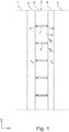
- Fig. 1 to Fig.3 show a tread pattern of a pneumatic vehicle tire for passenger cars in radial design.
- the tread pattern is a summer tire tread.
- Fig. 1 shows a section of a tread pattern within the ground contact width of a pneumatic vehicle tire, arranged in the axial direction A of the pneumatic vehicle tire next to each other a tread rib 1, a circumferential groove 4, a profile block row 2, a circumferential groove 5 and a tread rib 3 are formed, each over the entire circumference of Pneumatic vehicle tire extends and are aligned in the circumferential direction U of the pneumatic vehicle tire.
- the tread rib 1 and the profile block row 2 are spaced apart in the axial direction A by the circumferential groove 4.
- the profile block row 2 and the profile rib 3 are spaced from each other in the axial direction A of the pneumatic vehicle tire by the circumferential groove 5.
- the profile block row 2 is arranged in a known manner from one another in the circumferential direction U of the pneumatic vehicle tire and each formed by transverse grooves 7 spaced apart profile block elements 6.
- the transverse grooves 7 extend in the axial direction A of the pneumatic vehicle tire from the circumferential groove 4 through the entire profile block row 2 and open into the circumferential groove 5.
- the profile block elements 6 are bounded radially outwardly with a radially outer surface 9, which is part of the ground contact surface forming lateral surface of the tread pattern.
- the transverse grooves 7 are - as in the Fig. 2 and 3 shown - bounded radially inward by a groove bottom 10.
- a web 8 is formed in the groove bottom 10, which rises in the radial direction R from the groove bottom 10 to the outside and transverse to the main extension direction of the transverse grooves 7 - ie in the illustrated embodiment transverse to the axial direction A and thus aligned in the circumferential direction U - extending from the one bounded by the respective transverse groove 7 profile block element 6 to the other limited by the transverse groove 7 profile block element 6 and the two profile block elements 6 to each other.
- the web 8 is limited in the radial direction to the outside by a maximum of the parabolic forming the maximum radial extension point 13 of the web in the cross-sectional plane.
- the cross section of the web 8 is thus in its cross-sectional contour along the extension of the axis perpendicular to the radial R -. in the illustrated embodiment along the extension of the axial direction A - starting from the one flank 11 formed in the transition to the groove bottom 10 via the flank 11, the maximum 13 and the edge 12 to the groove bottom 10 with monotonically decreasing slope of the contour.
- the flanks 11 and 12 form in the direction perpendicular to the main extension direction of the webs and thus in the illustrated embodiment, perpendicular to the circumferential direction U formed cross sections, the legs of the parabola with maximum 13th
- the outer contour line 14 of the web 8 is - as shown and explained - parabolic with in the radial direction R inwardly directed opening formed.
- Fig. 2 is a Cartesian xy coordinate system in the transverse planes perpendicular to the main extension direction of the webs 8 - ie in the illustrated embodiment, perpendicular to the circumferential direction of the vehicle tire - drawn, the origin of the xy coordinate system in the maximum radial extension point 13 of the web 8 and the sectional contour 14 of the web and wherein the x-coordinate corresponds to the axial direction A and the y-coordinate corresponds to the radial direction R.
- the circumferential grooves 4 and 5 are formed with a measured in the radial direction R maximum tread depth P T.
- the distance h 1 measured in the radial direction R between the radially outer surface 9 of the tread block elements 6 and the maximum 13 of the webs 8 is formed with 0 mm ⁇ h 1 ⁇ (1/3 P T ).
- Fig.2 and Figure 3 an embodiment is shown in which the groove bottom 10 in the extension portion of the width a between the respective web 8 and the immediately adjacent circumferential groove 4 and 5 in the radial direction R at a distance h a from the maximum 13 and at the groove bottom 10 in the extension section between the two Webs 8 of the transverse groove 7 is formed in the radial direction R at a distance h i from the maximum 13, where hi ⁇ h a and (h 1 + ha) ⁇ P T.
- (h 1 + h a ) P T is formed.
- the distance h i is formed with (0.5 ha) ⁇ h i ⁇ h a .
- H i (0.8 h a ) is formed in the illustrated embodiment.
- h a h i and thus the groove bottom 10 is formed between the webs 8 and between the webs 8 and the respectively adjacent circumferential grooves 4 and 5 respectively at the same radial distance from the maximum 13.
- the contour line 14 is formed as part of a starting in the radial direction R outwardly formed maximum extension point 13 of the web 8 in the radial direction R inwardly open semi-ellipse, wherein the longer of the two major axes of the ellipse in the radial Direction R extends is formed.
- the maximum extension point 13 lies on the longer of the two main axes of the ellipse.
- the shorter of the two main axes extends perpendicular thereto in a radial position below the groove bottom 10 of the transverse groove 7 and extends when applied to the illustrated embodiment in the axial direction A of the pneumatic vehicle tire.
- a further embodiment is shown, in which additionally between rounded web edge 12 and groove bottom 10, a rounded transition 16 and between land flank 14 and groove bottom 10, a rounded transition 15 of the contour line 14 is formed.
- the rounding in the transition 16 is formed in the illustrated embodiment with a radius of curvature of 1 mm.
- the rounding of the transition 16 with the same radius of curvature - for example 3mm - is formed, which is formed for the transition between the facing to the profile block elements 6 groove wall of the adjacent circumferential groove 4 and 5 to the groove bottom of the circumferential groove 4 at.5 ,
- the rounding in the transition 15 is in the illustrated embodiment with a radius of curvature of less than or equal to 1 mm - for example, 1mm - formed.
Landscapes
- Engineering & Computer Science (AREA)
- Mechanical Engineering (AREA)
- Tires In General (AREA)
Abstract
Description
- Die Erfindung betrifft einen Fahrzeugluftreifen - insbesondere für Personenkraftwagen - mit Laufstreifenprofil mit Rillen, welche jeweils zwei radial erhabene Profilelementen voneinander trennen, mit wenigstens einem in einer Rille ausgebildeten Steg, welcher quer zur Haupterstreckungsrichtung der Rille durch die Rille hindurch erstreckt ausgebildet ist und die beiden Profilelemente miteinander verbindet und welcher in radialer Richtung R ausgehend vom Rillengrund der Rille bis in einen radialen Abstand h1 > 0 von der die Bodenkontaktoberfläche bildenden Mantelfläche des Laufstreifenprofiles erstreckt ausgebildet ist.
- Laufstreifenprofile von Pkw-Reifen mit Profilblockreihen, in denen in Umfangsrichtung hintereinander angeordnete Profilblockelemente jeweils durch Querrillen voneinander getrennt sind, sind bekannt. Es ist bekannt, bei derartigen Laufstreifenprofilen in Umfangsrichtung benachbarte Profilblockelemente der Profilblockreihe durch in der Querrille ausgebildete Stege, welche sich quer zur Erstreckungsrichtung der Querrille von Profilblockelement zu Profilblockelement hindurch erstrecken, durch die Querrille hindurch an einander anzubinden, um auf diese Weise die zwecks guter Aquaplaning- und Nassgriffeigenschaften gewünschten Profilblockreihen mit einer verbesserten Umfangssteifigkeit auszubilden.
- Es ist wünschenswert, derartige Stege zur Aufrechterhaltung eines hohen Profilnegativanteils in den Querrillen möglichst schmal auszubilden. Hierdurch unterliegen die Stege im Anbindungsbereich an das jeweilige Profilblockelement einer erhöhten Rissgefahr und sind bei der Herstellung des Reifens schwer rissfrei ein- und/oder ausformbar. Zur Vermeidung der Rissbildung und zur Sicherstellung einer rissbildungsfreien Ein- und/oder Ausformung ist es wünschenswert, die Stege relativ breit auszubilden, wodurch jedoch der Negativanteil der Querrille und somit die Aquaplaning-Fähigkeit eingeschränkt werden können.
- Der Erfindung liegt die Aufgabe zugrunde, in einfacher Weise derartige Fahrzeugluftreifen unter Nutzung der Funktion und der Vorteile von Stegen mit verbesserter Ein- und Ausformbarkeit auszubilden.
- Die Aufgabe wird erfindungsgemäß durch Ausbildung eines Fahrzeugluftreifens - insbesondere für Personenkraftwagen - mit Laufstreifenprofil mit Rillen, welche jeweils zwei radial erhabene Profilelementen voneinander trennen, mit wenigstens einem in einer Rille ausgebildeten Steg, welcher quer zur Haupterstreckungsrichtung der Rille durch die Rille hindurch erstreckt ausgebildet ist und die beiden Profilelemente miteinander verbindet und welcher in radialer Richtung R ausgehend vom Rillengrund der Rille bis in einen radialen Abstand h1 > 0 von der die Bodenkontaktoberfläche bildenden Mantelfläche des Laufstreifenprofiles erstreckt ausgebildet ist, gemäß den Merkmalen von Anspruch 1 gelöst, bei dem der Steg in seinen Querschnittebenen senkrecht zu seiner von Profilelement zu Profilelement gerichteten Haupterstreckungsrichtung längs seiner radialen Erstreckung von innen nach außen mit einer progressiv abnehmenden Breite ausgebildet ist.
- Diese Ausbildung ermöglicht durch die Formgebung der Stege eine einfache und sichere Ein- und/oder Ausformung des Laufstreifenprofiles im Bereich der Stege unter Reduktion von Rissbildung, wodurch die Vorteile der Stege zur Verbindung von Profilelementen auch bei schmalen Stegen in größerem Umfang genutzt und mehr Freiheitsgrade in der Konstruktion von Reifen ermöglicht werden können.
- Besonders vorteilhaft ist die Ausbildung eines Fahrzeugluftreifens gemäß den Merkmalen von Anspruch 2, wobei der Querschnitt mit einer Querschnittskontur mit von der einen Flanke des Steges bis zur anderen Flanke des Steges mit monoton fallender Steigung zu der zur Radialen R senkrecht ausgebildeten Achse in der Querschnittebene verlaufend ausgebildet ist. Hierdurch kann die maximale Kraft zum Aufbau des Einpressdrucks zuverlässig während der Einformung stetig aufgebaut werden.
- Besonders vorteilhaft zum Aufbau des Einpressdrucks ist die Ausbildung eines Fahrzeugluftreifens gemäß den Merkmalen von Anspruch 3, wobei der Querschnitt mit einer Querschnittkontur ausgebildet ist, die eine Parabel mit in radialer Richtung R nach innen hin geöffneten Schenkeln bildet.
- Besonders vorteilhaft ist die Ausbildung eines Fahrzeugluftreifens gemäß den Merkmalen von Anspruch 4, wobei der Querschnitt mit einer Querschnittkontur ausgebildet ist, die die Hälfte einer Ellipse bildet, deren längere Hauptachse im Wesentlichen in radialer Richtung R erstreckt ist. Diese Ausbildung ermöglicht aufgrund des Steigungsverlaufes ihrer Flanken eine besonders gute Ein- und Ausformbarkeit auch bei Stegen mit großer radialer Erstreckungshöhe unter Beibehaltung einer kleinen Stegbreite.
- Besonders vorteilhaft ist die Ausbildung eines Fahrzeugluftreifens gemäß den Merkmalen von Anspruch 5, wobei die beiden den Steg begrenzenden Stegflanken im Querschnitt mit abgerundetem Übergang zum Rillengrund ausgebildet sind. Hierdurch können die Kerbkräfte im Rillengrund zusätzlich reduziert werden.
- Besonders vorteilhaft ist die Ausbildung eines Fahrzeugluftreifens gemäß den Merkmalen von Anspruch 6, wobei die Profilelemente Profilblockelemente einer Profilblockreihe und die Rille eine Quer- oder Schrägrille der Profilblockreihe bildet.
- Besonders vorteilhaft ist die Ausbildung eines Fahrzeugluftreifens gemäß den Merkmalen von Anspruch 7, wobei in der Rille zwei in axialer Richtung A des Reifens von einander beabstandete Stege ausgebildet sind, die die beiden Profilblockelemente miteinander verbinden. Dies ermöglicht eine Stabilisierung der Blockecken der Profilblockelemente und die Einstellung der jeweils benötigten Quer- und Längssteifigkeit der Profilblockelemente und der Profilblockreihe.
- Besonders vorteilhaft ist die Ausbildung eines Fahrzeugluftreifens gemäß den Merkmalen von Anspruch 8, wobei der Steg mit einem Abstand a zur nächstgelegenen Umfangsrille ausgebildet ist mit 0mm≤ a ≤ 2mm ausgebildet ist. Der Steg im axialen Endbereich der Querrille bewirkt eine Versteifung sowohl in Umfangsrichtung als auch eine Versteifung gegen Verwindung des Profilblockelementes um eine radiale Achse durch das Profilblockelement und gegen eine Verbiegung um Parallelen zur Umfangsrichtung im axialen Endbereichen des Profilblockelementes. Die zwischen der von der benachbarten Umfangsrille gebildeten Rillenwand und der Profilblockelementmantelfläche gebildete Kante ist ebenfalls gegen Verbiegen gesichert, wodurch die Handling-Eigenschaften zusätzlich verbessert werden. Die für das Handling wichtige von der axial das Profilblockelement begrenzenden Rillenwand der Umfangsrille und von der in Umfangsrichtung das Profilblockelement begrenzenden Rillenwand der Querrille eingeschlossene Profilblockelementecke ist ebenfalls gegen Verwindung gesichert, wodurch sie ihre volle für das Handling wichtige Griffwirkung entfalten kann.
- Die Erfindung ist im Folgenden an Hand der in den
Figuren 1 bis 3 dargestellten Ausführungsbeispiele am Beispiel eines PKW-Sommerreifens radialer Bauart näher erläutert. Darin zeigen - Fig. 1
- einen Umfangsabschnitt eines Laufstreifenprofils eines Fahrzeugluftreifens für Personenkraftwagen mit Sommerreifenprofil,
- Fig. 2
- den Querschnitt durch eine Profilblockelementreihe von
Fig. 1 gemäß Schnittdarstellung 11-11 vonFig.1 und - Fig. 3
- den Querschnitt durch das Laufstreifenprofil von
Fig.1 gemäß Schnittdarstellung 111-111 vonFig.1 . - Die
Fig. 1 bis Fig.3 zeigen ein Laufstreifenprofil eines Fahrzeugluftreifes für Personenkraftwagen in radialer Bauart. Das Laufstreifenprofil ist ein Sommerreifenprofil.Fig. 1 zeigt einen Ausschnitt eines Laufstreifenprofils innerhalb der Bodenaufstandsbreite eines Fahrzeugluftreifens, bei dem in axialer Richtung A des Fahrzeugluftreifens nebeneinander angeordnet eine Profilrippe 1, eine Umfangsrille 4, eine Profilblockreihe 2, eine Umfangsrille 5 und eine Profilrippe 3 ausgebildet sind, die jeweils über den gesamten Umfang des Fahrzeugluftreifens erstreckt und in Umfangsrichtung U des Fahrzeugluftreifens ausgerichtet sind. Die Profilrippe 1 und die Profilblockreihe 2 sind in axialer Richtung A durch die Umfangsrille 4 voneinander beabstandet. Die Profilblockreihe 2 und die Profilrippe 3 sind in axialer Richtung A des Fahrzeugluftreifens durch die Umfangsrille 5 voneinander beabstandet. Die Profilblockreihe 2 ist in bekannter Weise aus in Umfangsrichtung U des Fahrzeugluftreifens hintereinander angeordneten und jeweils durch Querrillen 7 voneinander beabstandeten Profilblockelementen 6 ausgebildet. Die Querrillen 7 erstrecken sich in axialer Richtung A des Fahrzeugluftreifens ausgehend von der Umfangsrille 4 durch die gesamte Profilblockreihe 2 hindurch und münden in die Umfangsrille 5. Die Profilblockelemente 6 sind nach radial außen hin mit einer radial äußeren Oberfläche 9 begrenzt, welche Teil der die Bodenkontaktoberfläche bildenden Mantelfläche des Laufstreifenprofils bildet. - Die Querrillen 7 sind - wie in den
Fig. 2 und3 dargestellt - nach radial innen hin durch einen Rillengrund 10 begrenzt. Im Abstand a von der Umfangsrille 4 und im Abstand a von der Umfangsrille 5 ist jeweils ein Steg 8 im Rillengrund 10 ausgebildet, welcher sich in radialer Richtung R aus dem Rillengrund 10 nach außen erhebt und quer zur Haupterstreckungsrichtung der Querrillen 7 - d. h. im dargestellten Ausführungsbeispiel quer zur axialen Richtung A und somit in Umfangsrichtung U ausgerichtet - von dem einen durch die jeweilige Querrille 7 begrenzten Profilblockelement 6 bis zu dem anderen durch die Querrille 7 begrenzten Profilblockelement 6 erstreckt und die beiden Profilblockelemente 6 an einander anbindet. In den senkrecht zu der von Profilblockelement 6 zu Profilblockelement weisenden Haupterstreckungsrichtung der Stege 8 und somit im dargestellten Ausführungsbeispiel senkrecht zur Umfangsrichtung U ausgebildeten Querschnittebenen ist der Steg 8 jeweils mit einer Schnittkonturlinie 14 und mit einer in radialer Richtung von innen nach außen hin progressiv abnehmenden Breite b des Steges ausgebildet, wobei die Breite b senkrecht zur radialen Richtung R gemessen wird. Dabei bildet die den jeweiligen Steg 8 zur unmittelbar benachbarten Umfangsrille 5 bzw. 4 hinweisenden Seite hin begrenzende Stegflanke 12 und die den jeweiligen Steg 8 zu der zum anderen in der Querrille 7 ausgebildeten Steg 8 hin- und somit von der unmittelbar benachbarten Umfangsrille 5 bzw. 4 wegweisenden Seite hin begrenzende Stegflanke 11 einen Konturverlauf der Schnittkonturlinie 14, der eine in radialer Richtung nach innen hin geöffneten Parabel bildet. Der Steg 8 ist in radialer Richtung nach außen hin durch einen das Maximum der Parabel bildenden maximalen radialen Erstreckungspunkt 13 des Steges in der Querschnittebene begrenzt. - Der Querschnitt des Steges 8 ist somit in seiner Querschnittkontur längs der Erstreckung der zur Radialen R senkrecht ausgebildeten Achse - d.h. im dargestellten Ausführungsbeispiel längs der Erstreckung der axialen Richtung A - ausgehend von der einen Flanke 11 im Übergang zum Rillengrund 10 über die Flanke 11, das Maximum 13 und die Flanke 12 zum Rillengrund 10 mit monoton fallender Steigung des Konturverlaufes ausgebildet. Die Flanken 11 und 12 bilden in den senkrecht zur Haupterstreckungsrichtung der Stege und somit im dargestellten Ausführungsbeispiel senkrecht zur Umfangsrichtung U ausgebildeten Querschnitten die Schenkel der Parabel mit Maximum 13.
- Die Außenkonturlinie 14 des Steges 8 ist - wie dargestellt und erläutert - parabelförmig mit in radialer Richtung R nach innen gerichteter Öffnung ausgebildet. In
Fig. 2 ist ein kartesisches x-y-Koordinatensystem in den Querschnittebenen senkrecht zur Haupterstreckungsrichtung der Stege 8 - d. h. im dargestellten Ausführungsbeispiel senkrecht zur Umfangsrichtung des Fahrzeugreifens - eingezeichnet, wobei der Ursprung des x-y-Koordinatensystems im maximalen radialen Erstreckungspunkt 13 des Steges 8 und der Schnittkontur 14 des Steges 8 liegt, und wobei die x-Koordinate der axialen Richtung A und die y-Koordinate der radialen Richtung R entspricht. Die Parabelform bildet eine Parabel der Funktion f(x) = - (m * x2n), wobei n eine ganze Zahl ist und wobei n > 0. - Im dargestellten Ausführungsbeispiel handelt es sich beispielsweise um eine Parabel vierten Grades - d. h. n=2 - , wobei m=1 gewählt ist.
- Die Umfangsrillen 4 und 5 sind mit einer in radialer Richtung R gemessenen maximalen Profiltiefe PT ausgebildet.
- Der Abstand a ist mit 0mm ≤ a ≤ 2 mm - beispielsweise mit a = 1,5 mm - ausgebildet. Der in radialer Richtung R gemessene Abstand h1 zwischen der radial äußeren Oberfläche 9 der Profilblockelemente 6 und dem Maximum 13 der Stege 8 ist mit 0mm < h1 ≤ (1/3 PT) ausgebildet.
- In
Fig.2 undFig.3 ist ein Ausführungsbeispiel dargestellt, bei dem der Rillengrund 10 im Erstreckungsabschnitt der Breite a zwischen dem jeweiligen Steg 8 und der unmittelbar benachbarten Umfangsrille 4 bzw. 5 in radialer Richtung R im Abstand ha vom Maximum 13 und bei dem Rillengrund 10 im Erstreckungsabschnitt zwischen den beiden Stegen 8 der Querrille 7 in radialer Richtung R im Abstand hi vom Maximum 13 ausgebildet ist, wobei hi < ha und (h1 + ha) ≤ PT. Im dargestellten Ausführungsbeispiel ist (h1 + ha) = PT ausgebildet. - Der Abstand hi ist mit (0,5 ha) ≤ hi ≤ ha ausgebildet. Im dargestellten Ausführungsbeispiel ist hi = (0,8 ha) ausgebildet.
- In einem nicht dargestellten Ausführungsbeispiel ist ha = hi und somit der Rillengrund 10 zwischen den Stegen 8 und zwischen den Stegen 8 und den jeweils angrenzenden Umfangsrillen 4 bzw.5 jeweils mit gleichem radialem Abstand vom Maximum 13 ausgebildet.
- In einer anderen nicht dargestellten Ausführung ist die Konturlinie 14 als Teil einer ausgehend vom in radialer Richtung R nach außen gebildeten maximalen Erstreckungspunkt 13 des Steges 8 in radialer Richtung R nach innen geöffneten Halbellipse ausgebildet, wobei die längere der beiden Hauptachsen der Ellipse in radialer Richtung R erstreckt ausgebildet ist. Der maximale Erstreckungspunkt 13 liegt auf der längeren der beiden Hauptachsen der Ellipse. Die kürzere der beiden Hauptachsen erstreckt sich senkrecht hierzu in einer radialen Position unterhalb des Rillengrundes 10 der Querrille 7 und verläuft bei Anwendung auf das dargestellte Ausführungsbeispiel in axialer Richtung A des Fahrzeugluftreifens.
- In
Fig. 2 ist ein weiteres Ausführungsbeispiel dargestellt, bei der zusätzlich zwischen Stegflanke 12 und Rillengrund 10 ein abgerundeter Übergang 16 und zwischen Stegflanke 14 und Rillengrund 10 ein abgerundeter Übergang 15 der Konturlinie 14 ausgebildet ist. - Die Abrundung im Übergang 16 ist im dargestellten Ausführungsbeispiel mit einem Krümmungsradius von 1 mm ausgebildet. In anderer nicht dargestellter Ausführung ist die Abrundung des Übergangs 16 mit dem gleichen Krümmungsradius - beispielsweise 3mm - ausgebildet, der für den Übergang zwischen der zu den Profilblockelementen 6 weisenden Rillenwand der angrenzenden Umfangsrille 4 bzw. 5 zum Rillengrund der Umfangsrille 4 bzw.5 ausgebildet ist.
- Die Abrundung im Übergang 15 ist im dargestellten Ausführungsbeispiel mit einem Krümmungsradius von kleiner oder gleich 1 mm - beispielsweise von 1mm - ausgebildet.
-
- 1
- Profilrippe
- 2
- Profilblockreihe
- 3
- Profilrippe
- 4
- Umfangsrille
- 5
- Umfangsrille
- 6
- Profilblockelement
- 7
- Querrille
- 8
- Steg
- 9
- Radial äußere Oberfläche
- 10
- Rillengrund
- 11
- Stegflanke
- 12
- Stegflanke
- 13
- Maximum
- 14
- Stegkontur
- 15
- Abrundung
- 16
- Abrundung
Claims (8)
- Fahrzeugluftreifen - insbesondere für Personenkraftwagen - mit Laufstreifenprofil mit Rillen (7), welche jeweils zwei radial erhabene Profilelemente (6) voneinander trennen, mit wenigstens einem in einer Rille (7) ausgebildeten Steg (8), welcher quer zur Haupterstreckungsrichtung der Rille (7) durch die Rille (7) hindurch erstreckt ausgebildet ist und die beiden Profilelemente (6) miteinander verbindet und welcher in radialer Richtung R ausgehend vom Rillengrund (10) der Rille (7) bis in einen radialen Abstand h1 > 0mm von der die Bodenkontaktoberfläche bildenden Mantelfläche (9) des Laufstreifenprofiles erstreckt ausgebildet ist, dadurch gekennzeichnet,
dass der Steg (8) in seinen Querschnittebenen senkrecht zu seiner von Profilelement (6) zu Profilelement (6) gerichteten Haupterstreckungsrichtung längs seiner radialen Erstreckung von innen nach außen mit einer progressiv abnehmenden Breite b ausgebildet ist. - Fahrzeugluftreifen gemäß den Merkmalen von Anspruch 1,
wobei der Querschnitt mit einer Querschnittskontur (14) mit von der einen Flanke (11) des Steges (8) bis zur anderen Flanke (12) des Steges (8) mit monoton fallender Steigung zu der zur Radialen R senkrecht ausgebildeten Achse in der Querschnittebene verlaufend ausgebildet ist. - Fahrzeugluftreifen gemäß den Merkmalen von einem oder mehreren der vorangegangenen Ansprüche,
wobei der Querschnitt mit einer Querschnittskontur (14) ausgebildet ist, die eine Parabel mit in radialer Richtung R nach innen hin geöffneten Schenkeln (11,12) bildet. - Fahrzeugluftreifen gemäß den Merkmalen von einem oder mehreren der Ansprüche 1 bis 3,
wobei der Querschnitt mit einer Querschnittskontur (14) ausgebildet ist, die die Hälfte einer Ellipse bildet, deren längere Hauptachse im Wesentlichen in radialer Richtung R erstreckt ist. - Fahrzeugluftreifen gemäß den Merkmalen von einem oder mehreren der vorangegangenen Ansprüche,
wobei die beiden den Steg (8) begrenzenden Stegflanken (11,12) im Querschnitt mit abgerundetem Übergang (15,16) zum Rillengrund (10) ausgebildet sind. - Fahrzeugluftreifen gemäß den Merkmalen von einem oder mehreren der vorangegangenen Ansprüche,
wobei die Profilelemente (6) Profilblockelemente einer Profilblockreihe (2) und die Rille (7) eine Quer- oder Schrägrille der Profilblockreihe (2) bildet. - Fahrzeugluftreifen gemäß den Merkmalen von Anspruch 6,
wobei in der Rille (7) zwei in axialer Richtung A des Reifens von einander beabstandete Stege (8) ausgebildet sind, die die beiden Profilblockelemente (6) miteinander verbinden. - Fahrzeugluftreifen gemäß den Merkmalen von Anspruch 6 oder 7,
wobei der Steg (8) mit einem Abstand a zur nächstgelegenen Umfangsrille (4,5) ausgebildet ist mit 0mm≤ a ≤ 2mm ausgebildet ist.
Applications Claiming Priority (1)
| Application Number | Priority Date | Filing Date | Title |
|---|---|---|---|
| DE102011001295A DE102011001295A1 (de) | 2011-03-15 | 2011-03-15 | Fahrzeugluftreifen |
Publications (2)
| Publication Number | Publication Date |
|---|---|
| EP2500186A1 true EP2500186A1 (de) | 2012-09-19 |
| EP2500186B1 EP2500186B1 (de) | 2019-06-26 |
Family
ID=45531204
Family Applications (1)
| Application Number | Title | Priority Date | Filing Date |
|---|---|---|---|
| EP12151015.0A Active EP2500186B1 (de) | 2011-03-15 | 2012-01-13 | Fahrzeugluftreifen mit teilweiser Rillengrundanhebung |
Country Status (2)
| Country | Link |
|---|---|
| EP (1) | EP2500186B1 (de) |
| DE (1) | DE102011001295A1 (de) |
Cited By (1)
| Publication number | Priority date | Publication date | Assignee | Title |
|---|---|---|---|---|
| DE102021205673A1 (de) | 2021-06-04 | 2022-12-08 | Continental Reifen Deutschland Gmbh | Fahrzeugluftreifen aufweisend eine Rille mit asymmetrischem Steg |
Citations (7)
| Publication number | Priority date | Publication date | Assignee | Title |
|---|---|---|---|---|
| EP0230765A1 (de) * | 1985-12-27 | 1987-08-05 | Sumitomo Rubber Industries Limited | Laufflächenprofil mit Blockelementen |
| EP0855292A1 (de) * | 1997-01-28 | 1998-07-29 | PIRELLI COORDINAMENTO PNEUMATICI S.p.A. | Reifen und Laufflächenprofil für Reifen, insbesondere für LKW und dergleichen |
| US20060016538A1 (en) * | 2004-07-20 | 2006-01-26 | Tetsuji Miyazaki | Pneumatic tire |
| EP1685981A1 (de) * | 2005-01-28 | 2006-08-02 | The Goodyear Tire & Rubber Company | Laufflächenprofil |
| WO2009060476A1 (en) * | 2007-11-05 | 2009-05-14 | Pirelli Tyre S.P.A. | Pneumatic tyre |
| DE102009026086A1 (de) * | 2009-07-01 | 2011-01-05 | Continental Reifen Deutschland Gmbh | Fahrzeugluftreifen |
| DE102010016978A1 (de) * | 2010-05-18 | 2011-11-24 | Continental Reifen Deutschland Gmbh | Fahrzeugluftreifen |
Family Cites Families (2)
| Publication number | Priority date | Publication date | Assignee | Title |
|---|---|---|---|---|
| JPH0310910A (ja) * | 1989-06-09 | 1991-01-18 | Bridgestone Corp | 重荷重用空気入りタイヤ |
| JPH10151915A (ja) * | 1996-11-21 | 1998-06-09 | Sumitomo Rubber Ind Ltd | 空気入りタイヤ |
-
2011
- 2011-03-15 DE DE102011001295A patent/DE102011001295A1/de not_active Withdrawn
-
2012
- 2012-01-13 EP EP12151015.0A patent/EP2500186B1/de active Active
Patent Citations (7)
| Publication number | Priority date | Publication date | Assignee | Title |
|---|---|---|---|---|
| EP0230765A1 (de) * | 1985-12-27 | 1987-08-05 | Sumitomo Rubber Industries Limited | Laufflächenprofil mit Blockelementen |
| EP0855292A1 (de) * | 1997-01-28 | 1998-07-29 | PIRELLI COORDINAMENTO PNEUMATICI S.p.A. | Reifen und Laufflächenprofil für Reifen, insbesondere für LKW und dergleichen |
| US20060016538A1 (en) * | 2004-07-20 | 2006-01-26 | Tetsuji Miyazaki | Pneumatic tire |
| EP1685981A1 (de) * | 2005-01-28 | 2006-08-02 | The Goodyear Tire & Rubber Company | Laufflächenprofil |
| WO2009060476A1 (en) * | 2007-11-05 | 2009-05-14 | Pirelli Tyre S.P.A. | Pneumatic tyre |
| DE102009026086A1 (de) * | 2009-07-01 | 2011-01-05 | Continental Reifen Deutschland Gmbh | Fahrzeugluftreifen |
| DE102010016978A1 (de) * | 2010-05-18 | 2011-11-24 | Continental Reifen Deutschland Gmbh | Fahrzeugluftreifen |
Cited By (1)
| Publication number | Priority date | Publication date | Assignee | Title |
|---|---|---|---|---|
| DE102021205673A1 (de) | 2021-06-04 | 2022-12-08 | Continental Reifen Deutschland Gmbh | Fahrzeugluftreifen aufweisend eine Rille mit asymmetrischem Steg |
Also Published As
| Publication number | Publication date |
|---|---|
| EP2500186B1 (de) | 2019-06-26 |
| DE102011001295A1 (de) | 2012-09-20 |
Similar Documents
| Publication | Publication Date | Title |
|---|---|---|
| DE102012105120B4 (de) | Laufstreifenprofil eines Fahrzeugreifens | |
| EP2892735B1 (de) | Fahrzeugluftreifen | |
| DE102015202613A1 (de) | Fahrzeugluftreifen | |
| EP2711200A1 (de) | Fahrzeugluftreifen | |
| DE102014213660A1 (de) | Fahrzeugluftreifen | |
| EP3100873B1 (de) | Fahrzeugluftreifen | |
| EP3183127B1 (de) | Fahrzeugluftreifen | |
| DE102012109069A1 (de) | Fahrzeugluftreifen | |
| DE102015202615A1 (de) | Fahrzeugluftreifen | |
| DE102019206654A1 (de) | Fahrzeugluftreifen | |
| EP2455234B1 (de) | Laufstreifenprofil eines Fahrzeugluftreifens | |
| EP3750723B1 (de) | Fahrzeugluftreifen | |
| EP3100872B1 (de) | Fahrzeugluftreifen | |
| EP3224060B1 (de) | Fahrzeugluftreifen | |
| EP2500186B1 (de) | Fahrzeugluftreifen mit teilweiser Rillengrundanhebung | |
| EP3658391B1 (de) | Laufstreifenprofil eines fahrzeugreifens | |
| EP3538383B1 (de) | Fahrzeugluftreifen | |
| DE102019207297A1 (de) | Fahrzeugluftreifen | |
| EP3890994B1 (de) | Laufstreifenprofil eines fahrzeugreifens | |
| EP2390116A1 (de) | Laufstreifenprofil eines Fahrzeugluftreifens | |
| DE102020205836A1 (de) | Fahrzeugluftreifen | |
| WO2016091417A1 (de) | Fahrzeugluftreifen | |
| EP3335907B1 (de) | Fahrzeugluftreifen | |
| EP3160771B1 (de) | Fahrzeugluftreifen | |
| DE102019213572A1 (de) | Fahrzeugluftreifen |
Legal Events
| Date | Code | Title | Description |
|---|---|---|---|
| PUAI | Public reference made under article 153(3) epc to a published international application that has entered the european phase |
Free format text: ORIGINAL CODE: 0009012 |
|
| AK | Designated contracting states |
Kind code of ref document: A1 Designated state(s): AL AT BE BG CH CY CZ DE DK EE ES FI FR GB GR HR HU IE IS IT LI LT LU LV MC MK MT NL NO PL PT RO RS SE SI SK SM TR |
|
| AX | Request for extension of the european patent |
Extension state: BA ME |
|
| 17P | Request for examination filed |
Effective date: 20130319 |
|
| 17Q | First examination report despatched |
Effective date: 20150311 |
|
| STAA | Information on the status of an ep patent application or granted ep patent |
Free format text: STATUS: EXAMINATION IS IN PROGRESS |
|
| RIC1 | Information provided on ipc code assigned before grant |
Ipc: B60C 11/03 20060101ALN20181211BHEP Ipc: B60C 11/13 20060101AFI20181211BHEP |
|
| GRAP | Despatch of communication of intention to grant a patent |
Free format text: ORIGINAL CODE: EPIDOSNIGR1 |
|
| STAA | Information on the status of an ep patent application or granted ep patent |
Free format text: STATUS: GRANT OF PATENT IS INTENDED |
|
| RIC1 | Information provided on ipc code assigned before grant |
Ipc: B60C 11/03 20060101ALN20190121BHEP Ipc: B60C 11/13 20060101AFI20190121BHEP |
|
| RIC1 | Information provided on ipc code assigned before grant |
Ipc: B60C 11/13 20060101AFI20190206BHEP Ipc: B60C 11/03 20060101ALN20190206BHEP |
|
| INTG | Intention to grant announced |
Effective date: 20190226 |
|
| GRAS | Grant fee paid |
Free format text: ORIGINAL CODE: EPIDOSNIGR3 |
|
| GRAA | (expected) grant |
Free format text: ORIGINAL CODE: 0009210 |
|
| STAA | Information on the status of an ep patent application or granted ep patent |
Free format text: STATUS: THE PATENT HAS BEEN GRANTED |
|
| AK | Designated contracting states |
Kind code of ref document: B1 Designated state(s): AL AT BE BG CH CY CZ DE DK EE ES FI FR GB GR HR HU IE IS IT LI LT LU LV MC MK MT NL NO PL PT RO RS SE SI SK SM TR |
|
| REG | Reference to a national code |
Ref country code: GB Ref legal event code: FG4D Free format text: NOT ENGLISH |
|
| REG | Reference to a national code |
Ref country code: CH Ref legal event code: EP |
|
| REG | Reference to a national code |
Ref country code: AT Ref legal event code: REF Ref document number: 1147849 Country of ref document: AT Kind code of ref document: T Effective date: 20190715 |
|
| REG | Reference to a national code |
Ref country code: DE Ref legal event code: R096 Ref document number: 502012014960 Country of ref document: DE |
|
| REG | Reference to a national code |
Ref country code: IE Ref legal event code: FG4D Free format text: LANGUAGE OF EP DOCUMENT: GERMAN |
|
| REG | Reference to a national code |
Ref country code: NL Ref legal event code: MP Effective date: 20190626 |
|
| PG25 | Lapsed in a contracting state [announced via postgrant information from national office to epo] |
Ref country code: AL Free format text: LAPSE BECAUSE OF FAILURE TO SUBMIT A TRANSLATION OF THE DESCRIPTION OR TO PAY THE FEE WITHIN THE PRESCRIBED TIME-LIMIT Effective date: 20190626 Ref country code: FI Free format text: LAPSE BECAUSE OF FAILURE TO SUBMIT A TRANSLATION OF THE DESCRIPTION OR TO PAY THE FEE WITHIN THE PRESCRIBED TIME-LIMIT Effective date: 20190626 Ref country code: NO Free format text: LAPSE BECAUSE OF FAILURE TO SUBMIT A TRANSLATION OF THE DESCRIPTION OR TO PAY THE FEE WITHIN THE PRESCRIBED TIME-LIMIT Effective date: 20190926 Ref country code: SE Free format text: LAPSE BECAUSE OF FAILURE TO SUBMIT A TRANSLATION OF THE DESCRIPTION OR TO PAY THE FEE WITHIN THE PRESCRIBED TIME-LIMIT Effective date: 20190626 Ref country code: HR Free format text: LAPSE BECAUSE OF FAILURE TO SUBMIT A TRANSLATION OF THE DESCRIPTION OR TO PAY THE FEE WITHIN THE PRESCRIBED TIME-LIMIT Effective date: 20190626 Ref country code: LT Free format text: LAPSE BECAUSE OF FAILURE TO SUBMIT A TRANSLATION OF THE DESCRIPTION OR TO PAY THE FEE WITHIN THE PRESCRIBED TIME-LIMIT Effective date: 20190626 |
|
| REG | Reference to a national code |
Ref country code: LT Ref legal event code: MG4D |
|
| PG25 | Lapsed in a contracting state [announced via postgrant information from national office to epo] |
Ref country code: LV Free format text: LAPSE BECAUSE OF FAILURE TO SUBMIT A TRANSLATION OF THE DESCRIPTION OR TO PAY THE FEE WITHIN THE PRESCRIBED TIME-LIMIT Effective date: 20190626 Ref country code: RS Free format text: LAPSE BECAUSE OF FAILURE TO SUBMIT A TRANSLATION OF THE DESCRIPTION OR TO PAY THE FEE WITHIN THE PRESCRIBED TIME-LIMIT Effective date: 20190626 Ref country code: BG Free format text: LAPSE BECAUSE OF FAILURE TO SUBMIT A TRANSLATION OF THE DESCRIPTION OR TO PAY THE FEE WITHIN THE PRESCRIBED TIME-LIMIT Effective date: 20190926 Ref country code: GR Free format text: LAPSE BECAUSE OF FAILURE TO SUBMIT A TRANSLATION OF THE DESCRIPTION OR TO PAY THE FEE WITHIN THE PRESCRIBED TIME-LIMIT Effective date: 20190927 |
|
| PG25 | Lapsed in a contracting state [announced via postgrant information from national office to epo] |
Ref country code: CZ Free format text: LAPSE BECAUSE OF FAILURE TO SUBMIT A TRANSLATION OF THE DESCRIPTION OR TO PAY THE FEE WITHIN THE PRESCRIBED TIME-LIMIT Effective date: 20190626 Ref country code: RO Free format text: LAPSE BECAUSE OF FAILURE TO SUBMIT A TRANSLATION OF THE DESCRIPTION OR TO PAY THE FEE WITHIN THE PRESCRIBED TIME-LIMIT Effective date: 20190626 Ref country code: SK Free format text: LAPSE BECAUSE OF FAILURE TO SUBMIT A TRANSLATION OF THE DESCRIPTION OR TO PAY THE FEE WITHIN THE PRESCRIBED TIME-LIMIT Effective date: 20190626 Ref country code: NL Free format text: LAPSE BECAUSE OF FAILURE TO SUBMIT A TRANSLATION OF THE DESCRIPTION OR TO PAY THE FEE WITHIN THE PRESCRIBED TIME-LIMIT Effective date: 20190626 Ref country code: EE Free format text: LAPSE BECAUSE OF FAILURE TO SUBMIT A TRANSLATION OF THE DESCRIPTION OR TO PAY THE FEE WITHIN THE PRESCRIBED TIME-LIMIT Effective date: 20190626 Ref country code: PT Free format text: LAPSE BECAUSE OF FAILURE TO SUBMIT A TRANSLATION OF THE DESCRIPTION OR TO PAY THE FEE WITHIN THE PRESCRIBED TIME-LIMIT Effective date: 20191028 |
|
| PG25 | Lapsed in a contracting state [announced via postgrant information from national office to epo] |
Ref country code: IT Free format text: LAPSE BECAUSE OF FAILURE TO SUBMIT A TRANSLATION OF THE DESCRIPTION OR TO PAY THE FEE WITHIN THE PRESCRIBED TIME-LIMIT Effective date: 20190626 Ref country code: IS Free format text: LAPSE BECAUSE OF FAILURE TO SUBMIT A TRANSLATION OF THE DESCRIPTION OR TO PAY THE FEE WITHIN THE PRESCRIBED TIME-LIMIT Effective date: 20191026 Ref country code: ES Free format text: LAPSE BECAUSE OF FAILURE TO SUBMIT A TRANSLATION OF THE DESCRIPTION OR TO PAY THE FEE WITHIN THE PRESCRIBED TIME-LIMIT Effective date: 20190626 Ref country code: SM Free format text: LAPSE BECAUSE OF FAILURE TO SUBMIT A TRANSLATION OF THE DESCRIPTION OR TO PAY THE FEE WITHIN THE PRESCRIBED TIME-LIMIT Effective date: 20190626 |
|
| PG25 | Lapsed in a contracting state [announced via postgrant information from national office to epo] |
Ref country code: TR Free format text: LAPSE BECAUSE OF FAILURE TO SUBMIT A TRANSLATION OF THE DESCRIPTION OR TO PAY THE FEE WITHIN THE PRESCRIBED TIME-LIMIT Effective date: 20190626 |
|
| PG25 | Lapsed in a contracting state [announced via postgrant information from national office to epo] |
Ref country code: PL Free format text: LAPSE BECAUSE OF FAILURE TO SUBMIT A TRANSLATION OF THE DESCRIPTION OR TO PAY THE FEE WITHIN THE PRESCRIBED TIME-LIMIT Effective date: 20190626 Ref country code: DK Free format text: LAPSE BECAUSE OF FAILURE TO SUBMIT A TRANSLATION OF THE DESCRIPTION OR TO PAY THE FEE WITHIN THE PRESCRIBED TIME-LIMIT Effective date: 20190626 |
|
| PG25 | Lapsed in a contracting state [announced via postgrant information from national office to epo] |
Ref country code: IS Free format text: LAPSE BECAUSE OF FAILURE TO SUBMIT A TRANSLATION OF THE DESCRIPTION OR TO PAY THE FEE WITHIN THE PRESCRIBED TIME-LIMIT Effective date: 20200224 |
|
| REG | Reference to a national code |
Ref country code: DE Ref legal event code: R097 Ref document number: 502012014960 Country of ref document: DE |
|
| PLBE | No opposition filed within time limit |
Free format text: ORIGINAL CODE: 0009261 |
|
| STAA | Information on the status of an ep patent application or granted ep patent |
Free format text: STATUS: NO OPPOSITION FILED WITHIN TIME LIMIT |
|
| PG2D | Information on lapse in contracting state deleted |
Ref country code: IS |
|
| 26N | No opposition filed |
Effective date: 20200603 |
|
| PG25 | Lapsed in a contracting state [announced via postgrant information from national office to epo] |
Ref country code: MC Free format text: LAPSE BECAUSE OF FAILURE TO SUBMIT A TRANSLATION OF THE DESCRIPTION OR TO PAY THE FEE WITHIN THE PRESCRIBED TIME-LIMIT Effective date: 20190626 Ref country code: SI Free format text: LAPSE BECAUSE OF FAILURE TO SUBMIT A TRANSLATION OF THE DESCRIPTION OR TO PAY THE FEE WITHIN THE PRESCRIBED TIME-LIMIT Effective date: 20190626 |
|
| REG | Reference to a national code |
Ref country code: CH Ref legal event code: PL |
|
| GBPC | Gb: european patent ceased through non-payment of renewal fee |
Effective date: 20200113 |
|
| REG | Reference to a national code |
Ref country code: BE Ref legal event code: MM Effective date: 20200131 |
|
| PG25 | Lapsed in a contracting state [announced via postgrant information from national office to epo] |
Ref country code: LU Free format text: LAPSE BECAUSE OF NON-PAYMENT OF DUE FEES Effective date: 20200113 Ref country code: GB Free format text: LAPSE BECAUSE OF NON-PAYMENT OF DUE FEES Effective date: 20200113 |
|
| PG25 | Lapsed in a contracting state [announced via postgrant information from national office to epo] |
Ref country code: LI Free format text: LAPSE BECAUSE OF NON-PAYMENT OF DUE FEES Effective date: 20200131 Ref country code: CH Free format text: LAPSE BECAUSE OF NON-PAYMENT OF DUE FEES Effective date: 20200131 Ref country code: BE Free format text: LAPSE BECAUSE OF NON-PAYMENT OF DUE FEES Effective date: 20200131 |
|
| PG25 | Lapsed in a contracting state [announced via postgrant information from national office to epo] |
Ref country code: IE Free format text: LAPSE BECAUSE OF NON-PAYMENT OF DUE FEES Effective date: 20200113 |
|
| REG | Reference to a national code |
Ref country code: AT Ref legal event code: MM01 Ref document number: 1147849 Country of ref document: AT Kind code of ref document: T Effective date: 20200113 |
|
| PG25 | Lapsed in a contracting state [announced via postgrant information from national office to epo] |
Ref country code: AT Free format text: LAPSE BECAUSE OF NON-PAYMENT OF DUE FEES Effective date: 20200113 |
|
| PG25 | Lapsed in a contracting state [announced via postgrant information from national office to epo] |
Ref country code: MT Free format text: LAPSE BECAUSE OF FAILURE TO SUBMIT A TRANSLATION OF THE DESCRIPTION OR TO PAY THE FEE WITHIN THE PRESCRIBED TIME-LIMIT Effective date: 20190626 Ref country code: CY Free format text: LAPSE BECAUSE OF FAILURE TO SUBMIT A TRANSLATION OF THE DESCRIPTION OR TO PAY THE FEE WITHIN THE PRESCRIBED TIME-LIMIT Effective date: 20190626 |
|
| PG25 | Lapsed in a contracting state [announced via postgrant information from national office to epo] |
Ref country code: MK Free format text: LAPSE BECAUSE OF FAILURE TO SUBMIT A TRANSLATION OF THE DESCRIPTION OR TO PAY THE FEE WITHIN THE PRESCRIBED TIME-LIMIT Effective date: 20190626 |
|
| REG | Reference to a national code |
Ref country code: DE Ref legal event code: R081 Ref document number: 502012014960 Country of ref document: DE Owner name: CONTINENTAL REIFEN DEUTSCHLAND GMBH, DE Free format text: FORMER OWNER: CONTINENTAL REIFEN DEUTSCHLAND GMBH, 30165 HANNOVER, DE |
|
| PGFP | Annual fee paid to national office [announced via postgrant information from national office to epo] |
Ref country code: DE Payment date: 20260131 Year of fee payment: 15 |
|
| PGFP | Annual fee paid to national office [announced via postgrant information from national office to epo] |
Ref country code: FR Payment date: 20260123 Year of fee payment: 15 |