EP2500180A1 - Rim assembly with pads and connection members to connect spokes - Google Patents
Rim assembly with pads and connection members to connect spokes Download PDFInfo
- Publication number
- EP2500180A1 EP2500180A1 EP11168258A EP11168258A EP2500180A1 EP 2500180 A1 EP2500180 A1 EP 2500180A1 EP 11168258 A EP11168258 A EP 11168258A EP 11168258 A EP11168258 A EP 11168258A EP 2500180 A1 EP2500180 A1 EP 2500180A1
- Authority
- EP
- European Patent Office
- Prior art keywords
- connection
- rim
- pads
- bridge
- rim assembly
- Prior art date
- Legal status (The legal status is an assumption and is not a legal conclusion. Google has not performed a legal analysis and makes no representation as to the accuracy of the status listed.)
- Granted
Links
- 238000009434 installation Methods 0.000 claims abstract description 28
- 238000003754 machining Methods 0.000 description 4
- 229910000838 Al alloy Inorganic materials 0.000 description 1
- 241001125929 Trisopterus luscus Species 0.000 description 1
- 238000004519 manufacturing process Methods 0.000 description 1
- 239000000463 material Substances 0.000 description 1
- 230000003068 static effect Effects 0.000 description 1
Images


Classifications
-
- B—PERFORMING OPERATIONS; TRANSPORTING
- B60—VEHICLES IN GENERAL
- B60B—VEHICLE WHEELS; CASTORS; AXLES FOR WHEELS OR CASTORS; INCREASING WHEEL ADHESION
- B60B21/00—Rims
- B60B21/06—Rims characterised by means for attaching spokes, i.e. spoke seats
- B60B21/062—Rims characterised by means for attaching spokes, i.e. spoke seats for bicycles
-
- B—PERFORMING OPERATIONS; TRANSPORTING
- B60—VEHICLES IN GENERAL
- B60B—VEHICLE WHEELS; CASTORS; AXLES FOR WHEELS OR CASTORS; INCREASING WHEEL ADHESION
- B60B2900/00—Purpose of invention
- B60B2900/30—Increase in
- B60B2900/311—Rigidity or stiffness
-
- B—PERFORMING OPERATIONS; TRANSPORTING
- B60—VEHICLES IN GENERAL
- B60B—VEHICLE WHEELS; CASTORS; AXLES FOR WHEELS OR CASTORS; INCREASING WHEEL ADHESION
- B60B2900/00—Purpose of invention
- B60B2900/70—Adaptation for
- B60B2900/711—High loads, e.g. by reinforcements
-
- B—PERFORMING OPERATIONS; TRANSPORTING
- B60—VEHICLES IN GENERAL
- B60Y—INDEXING SCHEME RELATING TO ASPECTS CROSS-CUTTING VEHICLE TECHNOLOGY
- B60Y2200/00—Type of vehicle
- B60Y2200/10—Road Vehicles
- B60Y2200/13—Bicycles; Tricycles
Definitions
- the present invention relates to a rim assembly, and more particularly, to a rim with pads and connection members, and the spokes are connected to the rim and the connection members.
- a conventional wheel generally includes a rim, a hub located at the center of the rim and the spokes connected between the rim and the hub.
- the rim is made by Aluminum Alloy and extruded to a straight strip which is cut and the two ends are connected to each other to form a circular rim.
- the rim includes a top connection bridge and a bottom connection bridge and two walls extend from two sides of the two connection bridges. The tire is engage to the walls and multiple installation holes are defined through the two connection bridges so as to be connected with the spokes.
- the manufacturers try to reduce the weight of the rim by reducing the material for making the rim while the structural strength and the static and kinetic statuses are remained the same.
- connection zone where the spokes are connected to the rim so that the thickness of the rim in the connection zone is made to be thicker than the rest part of the rim. It is important to increase the strength at the connection zone to bear the stress while the rim is still light.
- the thickness of the rim is milled or cut to have the desired thickness.
- Taiwan Utility Patent No. 089213822 discloses a bicycle rim which includes a top connection bridge and a bottom connection bridge and two walls extend from two sides of the two connection bridges. Multiple installation holes are defined through the bottom connection bridge or the walls so as to be connected with the spokes. The thickness of the bottom connection bridge and the one of the two walls that has the installation holes are thicker than the rest parts of the bottom connection bridge and the wall.
- Another bicycle rim is disclosed in China Patent No. 200410062041.X which includes a thickness increment or a thickness decrement located between the bottom connection bridge and the adjacent spoke connection area so as to form a sharp angular turn portion which is connected with a connection zone and the radius of the curvature of the connection zone is equal or less than 0.4 mm.
- the first example discloses the thicker portion at the bottom connection bridge or the wall that has the installation holes, and the thinner portion at the portion between the spoke connection positions.
- the different thickness makes the connection bridge or the wall have wave-shaped change.
- the second example shows that the rim includes a sharp angular turn portion between two spokes connected to the connection bridge or the wall.
- both of the two examples have to be machined separately so as to machine the rim to have thicker and thinner portions.
- the machining processes involve the risk that cuts too much or even breaks the rim.
- the present invention intends to provide a rim that has pads and connection members and the spokes are connected to the rim by the pads and connection members.
- the present invention relates to a rim assembly and includes a rim having a first connection bridge and a second connection bridge, and two walls extend from two sides of the first and second connection bridges.
- the first connection bridge is located close to the center of the rim.
- the first and second connection bridges each have multiple installation holes.
- a pad unit includes multiple pads and each pad has a through hole. The pads are located on a surface of the first connection bridge and the through holes are in alignment with the installation holes.
- Multiple connection members each have a passage, the connection members respectively extend through the installation holes and the through holes.
- the spokes are securely connected to the passages.
- the thickness of the rim is thin and the pads reinforce the connection positions where the spokes are connected. No extra machining processes are needed.
- An object of the invention is therefore a rim assembly comprising:
- the primary object of the present invention is to provide a rim assembly where pads are connected to the installation holes of the rim and connection members are cooperated with the pads to increase the structural strength of the positions where the spokes are connected to the rim.
- Another object of the present invention is to provide a rim assembly wherein the thickness of the rim is remained the thin thickness and only the positions where the spokes are connected to the rim are reinforced so that the wheel can be assembled at low cost.
- connection members can be rivets or composed of two pieces which are threadedly connected to each other.
- the rim can be assembled conveniently.
- the rim assembly of the present invention comprises a rim 10, a pad unit, and a connection member unit.
- the rim 10 has a first connection bridge 11 and a second connection bridge 12, two walls 13 extending from two sides of the first and second connection bridges 11, 12, wherein the first connection bridge 11 is located close to the center of the rim 10 and the first and second connection bridges 11, 12 share a common center of the rim 10.
- the rim 10 has an inverted A-shaped end cross sectional view.
- the walls 13 have lips for connected with the tire (not shown).
- the first connection bridge 11 has multiple first installation holes 16 and the second connection bridge 12 has multiple second installation holes 15 so as to form a connection zone where heads 41 of spokes 40 are connected to the rim 10.
- the diameter of the second installation holes 15 is larger than that of the first installation holes 16.
- the pad unit includes multiple pads 20 and each pad 20 has a through hole 21.
- the pads 20 each are an elongate pad and includes a long side 22 and a short side 23.
- the length "A" of the long side 22 is longer than the length "B" of the short side 23.
- the pads 20 are located on a surface of the first connection bridge 11 and the through holes 21 are in alignment with the first installation holes 16.
- the surface mentioned above faces the second connection bridge 12 as shown in Figs. 2 and 3 .
- the connection member unit includes multiple connection members 30 and each connection member 30 has a passage 31.
- the connection members 30 respectively extend through the first installation holes 16 and the through holes 21, and the spokes 40 securely connected to the passages 31.
- the head 41 of the spoke 40 does not contact the second connection bridge 12 so that the rim 10 is not deformed when significant stress is applied to the spokes 40.
- the connection members 30 are rivets to connect the first connection bridge 11 and the pads 20.
- the rim 10 can be made to have thin thickness and the pads 20 reinforce the structural strength of the first connection bridge 11.
- the connection members 30 connect the first connection bridge 11 and the pads 20 to reinforce the strength of the connection zone 17 which does not need any extra machining process.
- the pads 20 can be located on the surface of the first connection bridge 11 and the surface is located opposite to the second connection bridge 12.
- the connection members 30 connect the first connection bridge 11 and the pads 20 to reinforce the strength of the connection zone 17.
- connection members 30 each are composed of a first connection piece 32 and a second connection piece 33 which is riveted to the first connection piece 32.
- the passage 31 is defined through the first and second connection pieces 32, 33.
- connection members 30 each are composed of a first connection piece 32 and a second connection piece 33 which is threadedly connected to the first connection piece 32 by their respective threaded portions 34.
- the passage 31 is defined through the first and second connection pieces 32, 33.
- Fig. 9 shows that the pads 20 each have two rounded ends which are located at the short sides 23.
- Fig. 10 shows that the pads 20 each are an oval pad and the long side 22 and the short side 23 are curved sides.
- connection members 30 can be rivets or composed of two pieces which are connected to each other by a rivet or by threadedly connection.
- the present invention provides the pads 20 located on the surface where the first installation holes 16 are located on the first connection bridge 11 and the pads 20 are cooperated with the connection members 30 to connect the spokes 40, so that the pads 20 increase the thickness and the strength of the rim 10 and the rim can be made to be thin and light in weight.
Landscapes
- Engineering & Computer Science (AREA)
- Mechanical Engineering (AREA)
- Tires In General (AREA)
- Steering Controls (AREA)
- Braking Arrangements (AREA)
- Connection Of Plates (AREA)
- Gasket Seals (AREA)
Abstract
Description
- The present invention relates to a rim assembly, and more particularly, to a rim with pads and connection members, and the spokes are connected to the rim and the connection members.
- A conventional wheel generally includes a rim, a hub located at the center of the rim and the spokes connected between the rim and the hub. The rim is made by Aluminum Alloy and extruded to a straight strip which is cut and the two ends are connected to each other to form a circular rim. The rim includes a top connection bridge and a bottom connection bridge and two walls extend from two sides of the two connection bridges. The tire is engage to the walls and multiple installation holes are defined through the two connection bridges so as to be connected with the spokes.
- The manufacturers try to reduce the weight of the rim by reducing the material for making the rim while the structural strength and the static and kinetic statuses are remained the same.
- The maximum stress is found at the connection zone where the spokes are connected to the rim so that the thickness of the rim in the connection zone is made to be thicker than the rest part of the rim. It is important to increase the strength at the connection zone to bear the stress while the rim is still light.
- When the rim is manufactured, the thickness of the rim is milled or cut to have the desired thickness.
- Taiwan Utility Patent No.
089213822 - Another bicycle rim is disclosed in China Patent No.
200410062041.X - The first example discloses the thicker portion at the bottom connection bridge or the wall that has the installation holes, and the thinner portion at the portion between the spoke connection positions. The different thickness makes the connection bridge or the wall have wave-shaped change. The second example shows that the rim includes a sharp angular turn portion between two spokes connected to the connection bridge or the wall.
- However, both of the two examples have to be machined separately so as to machine the rim to have thicker and thinner portions. The machining processes involve the risk that cuts too much or even breaks the rim.
- The present invention intends to provide a rim that has pads and connection members and the spokes are connected to the rim by the pads and connection members.
- The present invention relates to a rim assembly and includes a rim having a first connection bridge and a second connection bridge, and two walls extend from two sides of the first and second connection bridges. The first connection bridge is located close to the center of the rim. The first and second connection bridges each have multiple installation holes. A pad unit includes multiple pads and each pad has a through hole. The pads are located on a surface of the first connection bridge and the through holes are in alignment with the installation holes. Multiple connection members each have a passage, the connection members respectively extend through the installation holes and the through holes. The spokes are securely connected to the passages. The thickness of the rim is thin and the pads reinforce the connection positions where the spokes are connected. No extra machining processes are needed.
- An object of the invention is therefore a rim assembly comprising:
- a rim having a first connection bridge and a second connection bridge, two walls extending from two sides of the first and second connection bridges, the first connection bridge located close to a center of the rim, the first connection bridge having multiple first installation holes and the second connection bridge having multiple second installation holes so as to form a connection zone where heads of spokes are connected to the rim;
- a pad unit having multiple pads and each pad having a through hole, the pads located on a surface of the first connection bridge and the through holes being in alignment with the first installation holes, and
- multiple connection members and each connection member having a passage, the connection members respectively extending through the first installation holes and the through holes, the spokes securely connected to the passages.
- The primary object of the present invention is to provide a rim assembly where pads are connected to the installation holes of the rim and connection members are cooperated with the pads to increase the structural strength of the positions where the spokes are connected to the rim.
- Another object of the present invention is to provide a rim assembly wherein the thickness of the rim is remained the thin thickness and only the positions where the spokes are connected to the rim are reinforced so that the wheel can be assembled at low cost.
- Yet another object of the present invention is to provide a rim assembly wherein the connection members can be rivets or composed of two pieces which are threadedly connected to each other. The rim can be assembled conveniently.
- The present invention will become more obvious from the following description when taken in connection with the accompanying drawings which show, for purposes of illustration only, a preferred embodiment in accordance with the present invention.
-
-
Fig. 1 is a perspective view to show a part of the rim assembly of the present invention; -
Fig. 2 is an end cross sectional view of the rim assembly of the present invention; -
Fig. 3 is a side cross sectional view of the rim assembly of the present invention; -
Fig. 4 shows the pad of the rim assembly of the present invention; -
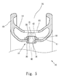
Fig. 5 is an end cross sectional view to show that a spoke is connected to the rim assembly of the present invention; -
Fig. 6 is an end cross sectional view the second embodiment of the rim assembly of the present invention; -
Fig. 7 is an end cross sectional view the third embodiment of the rim assembly of the present invention; -
Fig. 8 is an end cross sectional view the fourth embodiment of the rim assembly of the present invention; -
Fig. 9 is an end cross sectional view the fifth embodiment of the rim assembly of the present invention, and -
Fig. 10 is an end cross sectional view the sixth embodiment of the rim assembly of the present invention. - Referring to
Figs. 1 to 5 , the rim assembly of the present invention comprises arim 10, a pad unit, and a connection member unit. - The
rim 10 has afirst connection bridge 11 and asecond connection bridge 12, twowalls 13 extending from two sides of the first andsecond connection bridges first connection bridge 11 is located close to the center of therim 10 and the first andsecond connection bridges rim 10. Therim 10 has an inverted A-shaped end cross sectional view. Thewalls 13 have lips for connected with the tire (not shown). Thefirst connection bridge 11 has multiplefirst installation holes 16 and thesecond connection bridge 12 has multiplesecond installation holes 15 so as to form a connection zone whereheads 41 ofspokes 40 are connected to therim 10. The diameter of thesecond installation holes 15 is larger than that of thefirst installation holes 16. - The pad unit includes
multiple pads 20 and eachpad 20 has a throughhole 21. Thepads 20 each are an elongate pad and includes along side 22 and ashort side 23. The length "A" of thelong side 22 is longer than the length "B" of theshort side 23. Thepads 20 are located on a surface of thefirst connection bridge 11 and the throughholes 21 are in alignment with thefirst installation holes 16. The surface mentioned above faces thesecond connection bridge 12 as shown inFigs. 2 and3 . The connection member unit includesmultiple connection members 30 and eachconnection member 30 has apassage 31. Theconnection members 30 respectively extend through thefirst installation holes 16 and the throughholes 21, and thespokes 40 securely connected to thepassages 31. Thehead 41 of thespoke 40 does not contact thesecond connection bridge 12 so that therim 10 is not deformed when significant stress is applied to thespokes 40. In this embodiment, theconnection members 30 are rivets to connect thefirst connection bridge 11 and thepads 20. - The
rim 10 can be made to have thin thickness and thepads 20 reinforce the structural strength of thefirst connection bridge 11. Theconnection members 30 connect thefirst connection bridge 11 and thepads 20 to reinforce the strength of theconnection zone 17 which does not need any extra machining process. - As shown in
Fig. 6 , thepads 20 can be located on the surface of thefirst connection bridge 11 and the surface is located opposite to thesecond connection bridge 12. Theconnection members 30 connect thefirst connection bridge 11 and thepads 20 to reinforce the strength of theconnection zone 17. -
Fig. 7 shows that theconnection members 30 each are composed of afirst connection piece 32 and asecond connection piece 33 which is riveted to thefirst connection piece 32. Thepassage 31 is defined through the first andsecond connection pieces -
Fig. 8 shows that theconnection members 30 each are composed of afirst connection piece 32 and asecond connection piece 33 which is threadedly connected to thefirst connection piece 32 by their respective threadedportions 34. Thepassage 31 is defined through the first andsecond connection pieces -
Fig. 9 shows that thepads 20 each have two rounded ends which are located at the short sides 23.Fig. 10 shows that thepads 20 each are an oval pad and thelong side 22 and theshort side 23 are curved sides. - The
pads 20 is pout on the first installation holes 16 to increase the thickness of the area around the first installation holes 16 so that when thespokes 40 are connected to therim 10, therim 10 is not deformed or broken. Therefore, the thickness of thefirst connection bridge 11 does not need to be thick so that the weight of therim 10 is reduced. No extra machining process is needed and therim 10 is manufactured at lower cost and the production risks are reduced. - The
connection members 30 can be rivets or composed of two pieces which are connected to each other by a rivet or by threadedly connection. - The present invention provides the
pads 20 located on the surface where the first installation holes 16 are located on thefirst connection bridge 11 and thepads 20 are cooperated with theconnection members 30 to connect thespokes 40, so that thepads 20 increase the thickness and the strength of therim 10 and the rim can be made to be thin and light in weight. - While we have shown and described the embodiment in accordance with the present invention, it should be clear to those skilled in the art that further embodiments may be made without departing from the scope of the present invention.
Claims (9)
- A rim assembly comprising:a rim having a first connection bridge and a second connection bridge, two walls extending from two sides of the first and second connection bridges, the first connection bridge located close to a center of the rim, the first connection bridge having multiple first installation holes and the second connection bridge having multiple second installation holes so as to form a connection zone where heads of spokes are connected to the rim;a pad unit having multiple pads and each pad having a through hole, the pads located on a surface of the first connection bridge and the through holes being in alignment with the first installation holes, andmultiple connection members and each connection member having a passage, the connection members respectively extending through the first installation holes and the through holes, the spokes securely connected to the passages.
- The rim assembly as claimed in claim 1, wherein the pads each are an elongate pad and includes a long side and a short side.
- The rim assembly as claimed in claim 2, wherein the pads each have two rounded ends.
- The rim assembly as claimed in claim 2, wherein the pads each are an oval pad and the long and short sides are curved sides.
- The rim assembly as claimed in claim 1, wherein the pads are located on the surface of the first connection bridge and the surface faces the second connection bridge.
- The rim assembly as claimed in claim 1, wherein the pads are located on the surface of the first connection bridge and the surface is located opposite to the second connection bridge.
- The rim assembly as claimed in claim 1, wherein the connection members each are an elongate member which is a rivet.
- The rim assembly as claimed in claim 1, wherein the connection members each are composed of a first connection piece and a second connection piece which is riveted to the first connection piece, the passage is defined through the first and second connection pieces.
- The rim assembly as claimed in claim 1, wherein the connection members each are composed of a first connection piece and a second connection piece which is threadedly connected to the first connection piece, the passage is defined through the first and second connection pieces.
Applications Claiming Priority (1)
| Application Number | Priority Date | Filing Date | Title |
|---|---|---|---|
| TW100204694U TWM411352U (en) | 2011-03-16 | 2011-03-16 | Improved structure for wheel rim |
Publications (2)
| Publication Number | Publication Date |
|---|---|
| EP2500180A1 true EP2500180A1 (en) | 2012-09-19 |
| EP2500180B1 EP2500180B1 (en) | 2015-03-18 |
Family
ID=45432245
Family Applications (1)
| Application Number | Title | Priority Date | Filing Date |
|---|---|---|---|
| EP11168258.9A Not-in-force EP2500180B1 (en) | 2011-03-16 | 2011-05-31 | Rim assembly with pads and connection members to connect spokes |
Country Status (4)
| Country | Link |
|---|---|
| US (1) | US8801108B2 (en) |
| EP (1) | EP2500180B1 (en) |
| CN (2) | CN102673309B (en) |
| TW (1) | TWM411352U (en) |
Cited By (1)
| Publication number | Priority date | Publication date | Assignee | Title |
|---|---|---|---|---|
| DE102013002968A1 (en) * | 2013-02-22 | 2014-08-28 | Dt Swiss Ag | Impeller for at least partially muscle-powered vehicles and in particular bicycles |
Families Citing this family (4)
| Publication number | Priority date | Publication date | Assignee | Title |
|---|---|---|---|---|
| TWM411352U (en) * | 2011-03-16 | 2011-09-11 | Kunshan Henry Metal Tech Co | Improved structure for wheel rim |
| US9290043B2 (en) * | 2011-08-19 | 2016-03-22 | Raphael Schlanger | Vehicle wheel spoke connection |
| CN105916700B (en) * | 2014-01-15 | 2020-02-14 | 蒂森克虏伯碳零部件有限公司 | Wheel incorporating a rim with a fibre composite rim and a disc |
| ES2856405T3 (en) * | 2014-10-27 | 2021-09-27 | ThyssenKrupp Carbon Components GmbH | Vehicle wheel and procedure for the manufacture of a vehicle wheel with a connection between a wheel rim and a wheel disc |
Citations (5)
| Publication number | Priority date | Publication date | Assignee | Title |
|---|---|---|---|---|
| GB189802536A (en) * | 1898-02-01 | 1898-11-12 | Thomas Henry Woollen | Improvements in Metallic Spoke Head or Nipple Washers for the Rims of Velocipede and like Wheels. |
| US2937905A (en) * | 1955-11-29 | 1960-05-24 | Altenburger Karl | Spoke connection for tubeless tire rim |
| EP1518717A1 (en) * | 2003-09-27 | 2005-03-30 | Jaanluen Industry Co., Ltd. | Wheel having detachably securing spokes |
| WO2006070415A1 (en) * | 2004-12-30 | 2006-07-06 | Alpina Raggi S.P.A. | Wheel for mounting tires of the tubeless type |
| EP1698489A2 (en) * | 2005-03-03 | 2006-09-06 | Rigida International BV | Reinforcement device for bicycle rims and wheels with such a rim |
Family Cites Families (13)
| Publication number | Priority date | Publication date | Assignee | Title |
|---|---|---|---|---|
| DE9320953U1 (en) * | 1992-07-15 | 1995-06-29 | Mavic (S.A.), Saint-Trivier-Sur-Moignans | Wheel rim |
| IT1292238B1 (en) * | 1997-03-28 | 1999-01-29 | Campagnolo Srl | SPOKE FOR BICYCLE WHEEL AND WHEEL INCLUDING SUCH SPOKE. |
| US6715844B2 (en) * | 1998-07-29 | 2004-04-06 | Rolf Dietrich | Tensioned spoked bicycle wheel assembly and method for connecting a spoke and rim therein |
| US6048035A (en) * | 1998-11-23 | 2000-04-11 | Alex Machine Industrial Co., Ltd. | Bicycle wheel rim |
| US6089672A (en) * | 1999-05-27 | 2000-07-18 | Alex Machine Industrial Co., Ltd. | Bicycle wheel rim |
| US6811228B2 (en) * | 2002-12-31 | 2004-11-02 | Tseng Ping Tien | Wheel having spoke solidly coupling device |
| TWM245074U (en) * | 2003-06-10 | 2004-10-01 | Jaan Luen Industry Co Ltd | Improved retaining structure for spoke of wheel rim |
| US20050023883A1 (en) * | 2003-08-01 | 2005-02-03 | Shimano Inc. | Bicycle rim |
| US20050194834A1 (en) * | 2004-03-03 | 2005-09-08 | Chun-Hsung Chen | Bicycle spoke fixture assembly |
| US20070035175A1 (en) * | 2005-08-09 | 2007-02-15 | Yen-Jiun Lin | Hub for a bicycle |
| US20090322145A1 (en) * | 2008-06-25 | 2009-12-31 | Damon Rinard | Spoked bicycle wheel assembly with non-perforated rim |
| US20100264722A1 (en) * | 2009-04-17 | 2010-10-21 | Teixeira Iv Charles R | Bicycle rim with mechanical spoke attachment |
| TWM411352U (en) * | 2011-03-16 | 2011-09-11 | Kunshan Henry Metal Tech Co | Improved structure for wheel rim |
-
2011
- 2011-03-16 TW TW100204694U patent/TWM411352U/en not_active IP Right Cessation
- 2011-05-09 US US13/103,205 patent/US8801108B2/en not_active Expired - Fee Related
- 2011-05-12 CN CN201110121956.3A patent/CN102673309B/en not_active Expired - Fee Related
- 2011-05-12 CN CN201120148818XU patent/CN202106799U/en not_active Expired - Lifetime
- 2011-05-31 EP EP11168258.9A patent/EP2500180B1/en not_active Not-in-force
Patent Citations (5)
| Publication number | Priority date | Publication date | Assignee | Title |
|---|---|---|---|---|
| GB189802536A (en) * | 1898-02-01 | 1898-11-12 | Thomas Henry Woollen | Improvements in Metallic Spoke Head or Nipple Washers for the Rims of Velocipede and like Wheels. |
| US2937905A (en) * | 1955-11-29 | 1960-05-24 | Altenburger Karl | Spoke connection for tubeless tire rim |
| EP1518717A1 (en) * | 2003-09-27 | 2005-03-30 | Jaanluen Industry Co., Ltd. | Wheel having detachably securing spokes |
| WO2006070415A1 (en) * | 2004-12-30 | 2006-07-06 | Alpina Raggi S.P.A. | Wheel for mounting tires of the tubeless type |
| EP1698489A2 (en) * | 2005-03-03 | 2006-09-06 | Rigida International BV | Reinforcement device for bicycle rims and wheels with such a rim |
Cited By (1)
| Publication number | Priority date | Publication date | Assignee | Title |
|---|---|---|---|---|
| DE102013002968A1 (en) * | 2013-02-22 | 2014-08-28 | Dt Swiss Ag | Impeller for at least partially muscle-powered vehicles and in particular bicycles |
Also Published As
| Publication number | Publication date |
|---|---|
| US8801108B2 (en) | 2014-08-12 |
| TWM411352U (en) | 2011-09-11 |
| US20120235467A1 (en) | 2012-09-20 |
| CN202106799U (en) | 2012-01-11 |
| EP2500180B1 (en) | 2015-03-18 |
| CN102673309B (en) | 2015-03-25 |
| CN102673309A (en) | 2012-09-19 |
Similar Documents
| Publication | Publication Date | Title |
|---|---|---|
| EP2500180A1 (en) | Rim assembly with pads and connection members to connect spokes | |
| US10611188B2 (en) | Bicycle wheels | |
| KR102272120B1 (en) | Vehicle wheel for passenger cars | |
| WO2007146260A2 (en) | Fabricated vehicle wheel | |
| US20180001701A1 (en) | DlSK WHEEL AND MANUFACTURING METHOD THEREOF | |
| EP2612765A2 (en) | Rim assembly | |
| US20170157681A1 (en) | Hole Saw with Open End Cap Geometry | |
| KR20230062670A (en) | Vehicle wheel disc, vehicle wheel including such a wheel disc and method for producing such a wheel disc and vehicle wheel | |
| EP2500182B1 (en) | Securing device for spokes | |
| US9821366B2 (en) | Disc brake rotor and method of manufacturing disc brake rotor | |
| JP2020535050A (en) | Carbon fiber spokes and their manufacturing method | |
| US20080302616A1 (en) | Brake disk with grooves | |
| US20050023884A1 (en) | Combination of bicycle spokes and rims | |
| EP3750720A1 (en) | Vehicle wheel for passenger cars | |
| EP2500181A1 (en) | Rim with recesses for connecting spokes | |
| US6662911B1 (en) | Brake shoe rivet | |
| EP2768680B1 (en) | Wheel rim | |
| US20140167492A1 (en) | Bicycle rim made with aluminum and carbon fibers | |
| EP3636522B1 (en) | Tube for a bicycle | |
| TWM498676U (en) | Bicycle rim | |
| CN101811416A (en) | Combined-type spoke | |
| CN219903908U (en) | Welded steel-aluminum combined hub | |
| US20060250021A1 (en) | Wire spoke wheel, and components for same | |
| CN210454313U (en) | Lightweight wheel | |
| TWI579158B (en) | Wheel structure |
Legal Events
| Date | Code | Title | Description |
|---|---|---|---|
| PUAI | Public reference made under article 153(3) epc to a published international application that has entered the european phase |
Free format text: ORIGINAL CODE: 0009012 |
|
| AK | Designated contracting states |
Kind code of ref document: A1 Designated state(s): AL AT BE BG CH CY CZ DE DK EE ES FI FR GB GR HR HU IE IS IT LI LT LU LV MC MK MT NL NO PL PT RO RS SE SI SK SM TR |
|
| AX | Request for extension of the european patent |
Extension state: BA ME |
|
| 17P | Request for examination filed |
Effective date: 20130319 |
|
| 17Q | First examination report despatched |
Effective date: 20130809 |
|
| GRAP | Despatch of communication of intention to grant a patent |
Free format text: ORIGINAL CODE: EPIDOSNIGR1 |
|
| INTG | Intention to grant announced |
Effective date: 20140925 |
|
| GRAS | Grant fee paid |
Free format text: ORIGINAL CODE: EPIDOSNIGR3 |
|
| GRAA | (expected) grant |
Free format text: ORIGINAL CODE: 0009210 |
|
| AK | Designated contracting states |
Kind code of ref document: B1 Designated state(s): AL AT BE BG CH CY CZ DE DK EE ES FI FR GB GR HR HU IE IS IT LI LT LU LV MC MK MT NL NO PL PT RO RS SE SI SK SM TR |
|
| REG | Reference to a national code |
Ref country code: GB Ref legal event code: FG4D |
|
| REG | Reference to a national code |
Ref country code: CH Ref legal event code: EP |
|
| REG | Reference to a national code |
Ref country code: IE Ref legal event code: FG4D |
|
| REG | Reference to a national code |
Ref country code: AT Ref legal event code: REF Ref document number: 716314 Country of ref document: AT Kind code of ref document: T Effective date: 20150415 |
|
| REG | Reference to a national code |
Ref country code: DE Ref legal event code: R096 Ref document number: 602011014722 Country of ref document: DE Effective date: 20150430 |
|
| REG | Reference to a national code |
Ref country code: NL Ref legal event code: VDEP Effective date: 20150318 |
|
| REG | Reference to a national code |
Ref country code: NL Ref legal event code: VDEP Effective date: 20150318 |
|
| PG25 | Lapsed in a contracting state [announced via postgrant information from national office to epo] |
Ref country code: LT Free format text: LAPSE BECAUSE OF FAILURE TO SUBMIT A TRANSLATION OF THE DESCRIPTION OR TO PAY THE FEE WITHIN THE PRESCRIBED TIME-LIMIT Effective date: 20150318 Ref country code: NO Free format text: LAPSE BECAUSE OF FAILURE TO SUBMIT A TRANSLATION OF THE DESCRIPTION OR TO PAY THE FEE WITHIN THE PRESCRIBED TIME-LIMIT Effective date: 20150618 Ref country code: FI Free format text: LAPSE BECAUSE OF FAILURE TO SUBMIT A TRANSLATION OF THE DESCRIPTION OR TO PAY THE FEE WITHIN THE PRESCRIBED TIME-LIMIT Effective date: 20150318 Ref country code: SE Free format text: LAPSE BECAUSE OF FAILURE TO SUBMIT A TRANSLATION OF THE DESCRIPTION OR TO PAY THE FEE WITHIN THE PRESCRIBED TIME-LIMIT Effective date: 20150318 Ref country code: HR Free format text: LAPSE BECAUSE OF FAILURE TO SUBMIT A TRANSLATION OF THE DESCRIPTION OR TO PAY THE FEE WITHIN THE PRESCRIBED TIME-LIMIT Effective date: 20150318 |
|
| REG | Reference to a national code |
Ref country code: AT Ref legal event code: MK05 Ref document number: 716314 Country of ref document: AT Kind code of ref document: T Effective date: 20150318 |
|
| REG | Reference to a national code |
Ref country code: LT Ref legal event code: MG4D |
|
| PG25 | Lapsed in a contracting state [announced via postgrant information from national office to epo] |
Ref country code: RS Free format text: LAPSE BECAUSE OF FAILURE TO SUBMIT A TRANSLATION OF THE DESCRIPTION OR TO PAY THE FEE WITHIN THE PRESCRIBED TIME-LIMIT Effective date: 20150318 Ref country code: LV Free format text: LAPSE BECAUSE OF FAILURE TO SUBMIT A TRANSLATION OF THE DESCRIPTION OR TO PAY THE FEE WITHIN THE PRESCRIBED TIME-LIMIT Effective date: 20150318 Ref country code: GR Free format text: LAPSE BECAUSE OF FAILURE TO SUBMIT A TRANSLATION OF THE DESCRIPTION OR TO PAY THE FEE WITHIN THE PRESCRIBED TIME-LIMIT Effective date: 20150619 |
|
| PG25 | Lapsed in a contracting state [announced via postgrant information from national office to epo] |
Ref country code: NL Free format text: LAPSE BECAUSE OF FAILURE TO SUBMIT A TRANSLATION OF THE DESCRIPTION OR TO PAY THE FEE WITHIN THE PRESCRIBED TIME-LIMIT Effective date: 20150318 |
|
| PG25 | Lapsed in a contracting state [announced via postgrant information from national office to epo] |
Ref country code: ES Free format text: LAPSE BECAUSE OF FAILURE TO SUBMIT A TRANSLATION OF THE DESCRIPTION OR TO PAY THE FEE WITHIN THE PRESCRIBED TIME-LIMIT Effective date: 20150318 Ref country code: SK Free format text: LAPSE BECAUSE OF FAILURE TO SUBMIT A TRANSLATION OF THE DESCRIPTION OR TO PAY THE FEE WITHIN THE PRESCRIBED TIME-LIMIT Effective date: 20150318 Ref country code: CZ Free format text: LAPSE BECAUSE OF FAILURE TO SUBMIT A TRANSLATION OF THE DESCRIPTION OR TO PAY THE FEE WITHIN THE PRESCRIBED TIME-LIMIT Effective date: 20150318 Ref country code: EE Free format text: LAPSE BECAUSE OF FAILURE TO SUBMIT A TRANSLATION OF THE DESCRIPTION OR TO PAY THE FEE WITHIN THE PRESCRIBED TIME-LIMIT Effective date: 20150318 Ref country code: RO Free format text: LAPSE BECAUSE OF FAILURE TO SUBMIT A TRANSLATION OF THE DESCRIPTION OR TO PAY THE FEE WITHIN THE PRESCRIBED TIME-LIMIT Effective date: 20150318 Ref country code: PT Free format text: LAPSE BECAUSE OF FAILURE TO SUBMIT A TRANSLATION OF THE DESCRIPTION OR TO PAY THE FEE WITHIN THE PRESCRIBED TIME-LIMIT Effective date: 20150720 |
|
| PG25 | Lapsed in a contracting state [announced via postgrant information from national office to epo] |
Ref country code: AT Free format text: LAPSE BECAUSE OF FAILURE TO SUBMIT A TRANSLATION OF THE DESCRIPTION OR TO PAY THE FEE WITHIN THE PRESCRIBED TIME-LIMIT Effective date: 20150318 Ref country code: IS Free format text: LAPSE BECAUSE OF FAILURE TO SUBMIT A TRANSLATION OF THE DESCRIPTION OR TO PAY THE FEE WITHIN THE PRESCRIBED TIME-LIMIT Effective date: 20150718 Ref country code: PL Free format text: LAPSE BECAUSE OF FAILURE TO SUBMIT A TRANSLATION OF THE DESCRIPTION OR TO PAY THE FEE WITHIN THE PRESCRIBED TIME-LIMIT Effective date: 20150318 |
|
| REG | Reference to a national code |
Ref country code: DE Ref legal event code: R097 Ref document number: 602011014722 Country of ref document: DE |
|
| REG | Reference to a national code |
Ref country code: CH Ref legal event code: PL |
|
| PLBE | No opposition filed within time limit |
Free format text: ORIGINAL CODE: 0009261 |
|
| STAA | Information on the status of an ep patent application or granted ep patent |
Free format text: STATUS: NO OPPOSITION FILED WITHIN TIME LIMIT |
|
| PG25 | Lapsed in a contracting state [announced via postgrant information from national office to epo] |
Ref country code: CH Free format text: LAPSE BECAUSE OF NON-PAYMENT OF DUE FEES Effective date: 20150531 Ref country code: LI Free format text: LAPSE BECAUSE OF NON-PAYMENT OF DUE FEES Effective date: 20150531 Ref country code: MC Free format text: LAPSE BECAUSE OF FAILURE TO SUBMIT A TRANSLATION OF THE DESCRIPTION OR TO PAY THE FEE WITHIN THE PRESCRIBED TIME-LIMIT Effective date: 20150318 Ref country code: DK Free format text: LAPSE BECAUSE OF FAILURE TO SUBMIT A TRANSLATION OF THE DESCRIPTION OR TO PAY THE FEE WITHIN THE PRESCRIBED TIME-LIMIT Effective date: 20150318 Ref country code: LU Free format text: LAPSE BECAUSE OF FAILURE TO SUBMIT A TRANSLATION OF THE DESCRIPTION OR TO PAY THE FEE WITHIN THE PRESCRIBED TIME-LIMIT Effective date: 20150531 |
|
| 26N | No opposition filed |
Effective date: 20151221 |
|
| GBPC | Gb: european patent ceased through non-payment of renewal fee |
Effective date: 20150618 |
|
| REG | Reference to a national code |
Ref country code: IE Ref legal event code: MM4A |
|
| PG25 | Lapsed in a contracting state [announced via postgrant information from national office to epo] |
Ref country code: SI Free format text: LAPSE BECAUSE OF FAILURE TO SUBMIT A TRANSLATION OF THE DESCRIPTION OR TO PAY THE FEE WITHIN THE PRESCRIBED TIME-LIMIT Effective date: 20150318 |
|
| PG25 | Lapsed in a contracting state [announced via postgrant information from national office to epo] |
Ref country code: GB Free format text: LAPSE BECAUSE OF NON-PAYMENT OF DUE FEES Effective date: 20150618 Ref country code: IE Free format text: LAPSE BECAUSE OF NON-PAYMENT OF DUE FEES Effective date: 20150531 |
|
| REG | Reference to a national code |
Ref country code: FR Ref legal event code: PLFP Year of fee payment: 6 |
|
| PG25 | Lapsed in a contracting state [announced via postgrant information from national office to epo] |
Ref country code: BE Free format text: LAPSE BECAUSE OF FAILURE TO SUBMIT A TRANSLATION OF THE DESCRIPTION OR TO PAY THE FEE WITHIN THE PRESCRIBED TIME-LIMIT Effective date: 20150318 |
|
| PG25 | Lapsed in a contracting state [announced via postgrant information from national office to epo] |
Ref country code: MT Free format text: LAPSE BECAUSE OF FAILURE TO SUBMIT A TRANSLATION OF THE DESCRIPTION OR TO PAY THE FEE WITHIN THE PRESCRIBED TIME-LIMIT Effective date: 20150318 |
|
| PG25 | Lapsed in a contracting state [announced via postgrant information from national office to epo] |
Ref country code: BG Free format text: LAPSE BECAUSE OF FAILURE TO SUBMIT A TRANSLATION OF THE DESCRIPTION OR TO PAY THE FEE WITHIN THE PRESCRIBED TIME-LIMIT Effective date: 20150318 Ref country code: SM Free format text: LAPSE BECAUSE OF FAILURE TO SUBMIT A TRANSLATION OF THE DESCRIPTION OR TO PAY THE FEE WITHIN THE PRESCRIBED TIME-LIMIT Effective date: 20150318 Ref country code: HU Free format text: LAPSE BECAUSE OF FAILURE TO SUBMIT A TRANSLATION OF THE DESCRIPTION OR TO PAY THE FEE WITHIN THE PRESCRIBED TIME-LIMIT; INVALID AB INITIO Effective date: 20110531 |
|
| REG | Reference to a national code |
Ref country code: FR Ref legal event code: PLFP Year of fee payment: 7 |
|
| PG25 | Lapsed in a contracting state [announced via postgrant information from national office to epo] |
Ref country code: CY Free format text: LAPSE BECAUSE OF FAILURE TO SUBMIT A TRANSLATION OF THE DESCRIPTION OR TO PAY THE FEE WITHIN THE PRESCRIBED TIME-LIMIT Effective date: 20150318 |
|
| PGFP | Annual fee paid to national office [announced via postgrant information from national office to epo] |
Ref country code: FR Payment date: 20170531 Year of fee payment: 7 Ref country code: DE Payment date: 20170531 Year of fee payment: 7 |
|
| PG25 | Lapsed in a contracting state [announced via postgrant information from national office to epo] |
Ref country code: TR Free format text: LAPSE BECAUSE OF FAILURE TO SUBMIT A TRANSLATION OF THE DESCRIPTION OR TO PAY THE FEE WITHIN THE PRESCRIBED TIME-LIMIT Effective date: 20150318 |
|
| PGFP | Annual fee paid to national office [announced via postgrant information from national office to epo] |
Ref country code: IT Payment date: 20170531 Year of fee payment: 7 |
|
| PG25 | Lapsed in a contracting state [announced via postgrant information from national office to epo] |
Ref country code: MK Free format text: LAPSE BECAUSE OF FAILURE TO SUBMIT A TRANSLATION OF THE DESCRIPTION OR TO PAY THE FEE WITHIN THE PRESCRIBED TIME-LIMIT Effective date: 20150318 |
|
| PG25 | Lapsed in a contracting state [announced via postgrant information from national office to epo] |
Ref country code: AL Free format text: LAPSE BECAUSE OF FAILURE TO SUBMIT A TRANSLATION OF THE DESCRIPTION OR TO PAY THE FEE WITHIN THE PRESCRIBED TIME-LIMIT Effective date: 20150318 |
|
| REG | Reference to a national code |
Ref country code: DE Ref legal event code: R119 Ref document number: 602011014722 Country of ref document: DE |
|
| PG25 | Lapsed in a contracting state [announced via postgrant information from national office to epo] |
Ref country code: IT Free format text: LAPSE BECAUSE OF NON-PAYMENT OF DUE FEES Effective date: 20180531 Ref country code: DE Free format text: LAPSE BECAUSE OF NON-PAYMENT OF DUE FEES Effective date: 20181201 Ref country code: FR Free format text: LAPSE BECAUSE OF NON-PAYMENT OF DUE FEES Effective date: 20180531 |