EP2500048A1 - Blood bag system and blood treatment method - Google Patents
Blood bag system and blood treatment method Download PDFInfo
- Publication number
- EP2500048A1 EP2500048A1 EP10829828A EP10829828A EP2500048A1 EP 2500048 A1 EP2500048 A1 EP 2500048A1 EP 10829828 A EP10829828 A EP 10829828A EP 10829828 A EP10829828 A EP 10829828A EP 2500048 A1 EP2500048 A1 EP 2500048A1
- Authority
- EP
- European Patent Office
- Prior art keywords
- bag
- tube
- blood
- density component
- relative
- Prior art date
- Legal status (The legal status is an assumption and is not a legal conclusion. Google has not performed a legal analysis and makes no representation as to the accuracy of the status listed.)
- Granted
Links
- 0 N*1CCCCCC1 Chemical compound N*1CCCCCC1 0.000 description 1
Images



Classifications
-
- A—HUMAN NECESSITIES
- A61—MEDICAL OR VETERINARY SCIENCE; HYGIENE
- A61M—DEVICES FOR INTRODUCING MEDIA INTO, OR ONTO, THE BODY; DEVICES FOR TRANSDUCING BODY MEDIA OR FOR TAKING MEDIA FROM THE BODY; DEVICES FOR PRODUCING OR ENDING SLEEP OR STUPOR
- A61M1/00—Suction or pumping devices for medical purposes; Devices for carrying-off, for treatment of, or for carrying-over, body-liquids; Drainage systems
- A61M1/02—Blood transfusion apparatus
- A61M1/029—Separating blood components present in distinct layers in a container, not otherwise provided for
-
- A—HUMAN NECESSITIES
- A61—MEDICAL OR VETERINARY SCIENCE; HYGIENE
- A61M—DEVICES FOR INTRODUCING MEDIA INTO, OR ONTO, THE BODY; DEVICES FOR TRANSDUCING BODY MEDIA OR FOR TAKING MEDIA FROM THE BODY; DEVICES FOR PRODUCING OR ENDING SLEEP OR STUPOR
- A61M1/00—Suction or pumping devices for medical purposes; Devices for carrying-off, for treatment of, or for carrying-over, body-liquids; Drainage systems
- A61M1/02—Blood transfusion apparatus
- A61M1/0209—Multiple bag systems for separating or storing blood components
- A61M1/0218—Multiple bag systems for separating or storing blood components with filters
-
- A—HUMAN NECESSITIES
- A61—MEDICAL OR VETERINARY SCIENCE; HYGIENE
- A61M—DEVICES FOR INTRODUCING MEDIA INTO, OR ONTO, THE BODY; DEVICES FOR TRANSDUCING BODY MEDIA OR FOR TAKING MEDIA FROM THE BODY; DEVICES FOR PRODUCING OR ENDING SLEEP OR STUPOR
- A61M1/00—Suction or pumping devices for medical purposes; Devices for carrying-off, for treatment of, or for carrying-over, body-liquids; Drainage systems
- A61M1/02—Blood transfusion apparatus
- A61M1/0209—Multiple bag systems for separating or storing blood components
- A61M1/0236—Multiple bag systems for separating or storing blood components with sampling means, e.g. sample bag or sampling port
-
- A—HUMAN NECESSITIES
- A61—MEDICAL OR VETERINARY SCIENCE; HYGIENE
- A61M—DEVICES FOR INTRODUCING MEDIA INTO, OR ONTO, THE BODY; DEVICES FOR TRANSDUCING BODY MEDIA OR FOR TAKING MEDIA FROM THE BODY; DEVICES FOR PRODUCING OR ENDING SLEEP OR STUPOR
- A61M1/00—Suction or pumping devices for medical purposes; Devices for carrying-off, for treatment of, or for carrying-over, body-liquids; Drainage systems
- A61M1/36—Other treatment of blood in a by-pass of the natural circulatory system, e.g. temperature adaptation, irradiation ; Extra-corporeal blood circuits
- A61M1/3693—Other treatment of blood in a by-pass of the natural circulatory system, e.g. temperature adaptation, irradiation ; Extra-corporeal blood circuits using separation based on different densities of components, e.g. centrifuging
Definitions
- the present invention relates to a blood bag system and a blood treatment method for centrifuging whole blood and storing individual blood components in respective bags.
- the blood (whole blood) obtained by blood donation is centrifuged to be thereby separated into a light supernatant PPP (platelet poor plasma) fraction, a heavy precipitated CRC (concentrated red cell) fraction, and buffy coat formed therebetween.
- the buffy coat contains leukocytes, platelets and red cells; especially, as for platelets, the proportion of young fresh ones is high.
- One conventional example of blood bag system includes a first bag (combined buffy coat bag and whole blood bag) for storing whole blood, a first tube connected at its one end to an upper portion of the first bag, a second bag (plasma bag) which is connected to the other end of the first tube and in which platelet poor plasma is to be stored, a second tube connected at its one end to a lower portion of the first tube, and a third bag (red cell bag) which is connected to the other end of the second tube and in which concentrated red cells are to be stored.
- a first bag combined buffy coat bag and whole blood bag
- a first tube connected at its one end to an upper portion of the first bag
- a second bag plasma bag
- second tube connected at its one end to a lower portion of the first tube
- red cell bag red cell bag
- the whole blood in the first bag is centrifuged to be separated into platelet poor plasma, concentrated red cells and buffy coat, and, thereafter, the platelet poor plasma is transported to the second bag through the first tube connected to an upper portion of the first bag, and the concentrated red cells are transported to the third bag through the second tube connected to a lower portion of the first bag.
- a centrifuging and transporting apparatus by which a step of centrifuging whole blood and a step of transporting blood components obtained by centrifugation can be performed by a single apparatus
- a configuration which includes a centrifugal drum having a plurality of unit insertion holes and driven to rotate in a circumferential direction and a plurality of insert units to be inserted in the unit insertion holes (see, for example, US Patent No. 6910998 ).
- the insert unit permits the above-mentioned blood bag system to be mounted thereto.
- a first bag in the above-mentioned blood bag system has a top-and-bottom (TAB) type bag structure in which a first tube is connected to an upper portion thereof and a second tube is connected to a lower portion thereof. Therefore, in mounting the first tube to the above-mentioned insert unit, the second tube provided at the lower portion of the first bag must be laid around upward from the lower side (bottom side) of the insert unit, and the handling operation is bothersome, so that it is difficult to smoothly carry out the mounting operation. In addition, if the second tube undergoes kinking (torsion or sharp bending) due to the handling of the second tube, the second tube may be closed, possibly making it impossible to transport blood components.
- TAB top-and-bottom
- the present invention has been made in consideration of the above-mentioned circumstances. Accordingly, it is an object of the present invention to provide a blood bag system and a blood treatment method such that the blood bag system can be easily mounted to a centrifuging and transporting apparatus and the problem of kinking of a tube due to handling of the tube can be solved.
- a blood bag system is characterized in that it includes: a first bag in which blood containing a plurality of components is stored; a second bag in which a relative medium-density component obtained by centrifugation of the blood in the first bag is stored; a third bag in which a relative low-density component obtained by centrifugation of the blood in the first bag is stored; a first tube through which an upper portion of the first bag and an inlet of the second bag are connected and through which the relative low-density component and the relative medium-density component are transported from the first bag to the second bag; and a second tube through which an outlet of the second bag and the third bag are connected and through which the relative low-density component is transported from the first bag to the third bag by way of the first tube and the second bag.
- blood containing a plurality of components and contained in the first bag is separated into three layers including a relative low-density component, a relative medium-density component and a relative high-density component by applying a centrifugal force to the blood, and the first bag is pressed so that the relative low-density component is transported from the first bag to the third bag through the first tube, the second bag and the second tube, whereas the relative medium-density component is transported from the first bag to the second bag through the first tube.
- the relative medium-density component is stored in the second bag, whereas the relative low-density component is stored in the third bag, and the remaining relative high-density component is stored in the first bag. Consequently, the blood can be separated into the relative low-density component, the relative medium-density component and the relative high-density components, and these components can be preserved in the respective bags.
- the first tube through which the relative medium-density component and the relative low-density component are transported from the first bag to the second bag and the third bag is connected to the upper portion of the first bag, so that a tube to be connected to a lower portion of the first bag is unnecessary, and tubes are connected only to the upper portion of the first bag in this configuration. Accordingly, the bag configuration is simplified, so that convenience for the user to use a blood bag system is enhanced. In addition, since handling of tubes in mounting the blood bag system to a centrifuging and transporting apparatus is facilitated, the mounting of the system to the centrifuging and transporting apparatus becomes easy to carry out.
- the second bag since the second bag is used only for storage of the relative medium-density component and its capacity may be set according to the amount of the relative medium-density component to be stored therein, the second bag can be reduced in size, as compared with a relative medium-density component bag according to the related art. Consequently, in the case where the relative medium-density component is buffy coat, it is possible to reduce the amount of buffy coat left in the second bag, and to enhance platelet recovery late, at the time of preparing a platelet preparation by buffy coat pooling conducted as a subsequent step.
- the blood bag system as above is characterized in that the second bag has a structure in which the cross-sectional area of a channel at the outlet is smaller than the cross-sectional area of a channel at the inlet.
- the rate of flow into the third bag is suppressed, whereby the relative medium-density component can be prevented from flowing into the third bag.
- the blood bag system as above is characterized in that it includes a first clamp by which the first tube is closed and opened; and a second clamp by which the second tube is closed and opened.
- the second clamp upon detection of the transfer of a predetermined component into the first tube at the time of transporting the relative low-density component and the relative medium-density component from the first bag to the second bag, the second clamp is operated to close the second tube, whereby the predetermined component is prevented from flowing into the third bag.
- the first tube closed by operating the first clamp when the first bag has been pressed by a predetermined amount it is possible to collect a predetermined amount of a blood component into the second bag and to prevent the relative high-density component from flowing into the second bag.
- the blood bag system as above is characterized in that it includes a fourth bag in which a relative high-density component transported from the first bag is stored; a filter which is disposed between the first bag and the fourth bag and by which predetermined cells are removed; a third tube through which an upper portion of the first bag and an inlet of the filter are connected and through which the relative high-density component is transported from the first bag to the filter; and a fourth tube through which an outlet of the filter and the fourth bag are connected and through which the relative high-density component is transported from the filter to the fourth bag.
- the just-mentioned configuration it is possible to filter the relative high-density component left in the first bag by a filter to thereby remove predetermined cells and to store in the fourth bag the relative high-density component freed of the predetermined cells.
- the third tube interconnecting the first bag and the filter is connected to the upper portion of the first bag, a tube connected to a lower portion of the first bag is unnecessary, and tubes are connected only to the upper portion of the first bag in this configuration. Accordingly, even in the configuration in which the filter is provided, it is easy to lay around the tubes in mounting the blood bag system to a centrifuging and transporting apparatus and, hence, it is easy to mount the blood bag system to the centrifuging and transporting apparatus.
- the blood bag system as above is characterized in that the blood containing the plurality of components is whole blood, and the relative low-density component, the relative medium-density component and the relative high-density component are plasma, buffy coat and concentrated red cells, respectively.
- a blood treatment method is characterized in that it includes: a centrifugation step of centrifuging blood containing a plurality of components into a relative low-density component, a relative medium-density component and a relative high-density component in a first bag; and a separation step of transporting the relative low-density component from the first bag to a third bag through a first tube connected to an upper portion of the first bag and transporting the relative medium-density component from the first bag to a second bag provided between the first bag and the third bag through the first tube, by pressing the first bag.
- the first bag is pressed, whereby the relative low-density component and the relative medium-density component are made to flow out from the first bag through the first tube in the order of the relative low-density component and the relative medium-density component, the relative low-density component is transported from the first bag to the third bag through the second bag and a second tube connected to an outlet of the second bag, and the relative medium-density component is transported to the second bag through the first tube.
- the relative medium-density component is stored in the second bag, whereas the relative low-density component is stored in the third bag, and the remaining relative high-density component is stored in the first bag.
- the tubes are connected only to the upper portion of the first bag. Therefore, the convenience in use of the blood bag system is enhanced through simplification of the bag configuration, and handling of the tubes at the time of mounting the blood bag system to a centrifuging and transporting apparatus is facilitated, whereby the mounting of the system to the centrifuging and transporting apparatus is facilitated.
- the second bag can be reduced in size, as compared with a relative medium-density component bag according to the related art.
- the relative medium-density component is buffy coat
- the amount of the buffy coat left in the second bag at the time of preparing a platelet preparation by buffy coat pooling can be reduced, and platelet recovery rate can be enhanced.
- the blood treatment method as above is characterized in that in the separation step, in transporting the relative low-density component and the relative medium-density component from the first bag to the second bag, the kind of a solution flowing through the first tube is detected, and a channel in the second tube is closed upon detection of transfer of the relative medium-density component into the first tube.
- the relative medium-density component is prevented from flowing into the third bag.
- the blood treatment method as above is characterized in that in the separation step, a channel in the first tube is closed when the first bag has been pressed by a predetermined amount.
- the blood treatment method as above is characterized in that it includes: a transportation step of transporting, after the separation step, the relative high-density component left in the first bag from the first bag to a filter by which predetermined cells are removed, through a third tube connected to an upper portion of the first bag, and transporting the relative high-density component passed through the filter from the filter to a fourth bag.
- the third tube for use in such a blood treatment method as this is connected to the upper portion of the first bag, a tube connected to a lower portion of the first bag is unnecessary, and tubes are connected only to the upper portion of the first bag in this configuration. Accordingly, even in the configuration wherein the filter is provided, it is easy to lay around the tubes at the time of mounting to a blood bag system for use in the blood treatment method to a centrifuging and transporting apparatus, and it is easy to mount the blood bag system to the centrifuging and transporting apparatus.
- the blood treatment method as above is characterized in that the blood containing the plurality of components is whole blood, and the relative low-density component, the relative medium-density component and the relative high-density component are plasma, buffy coat and concentrated red cells, respectively.
- FIG. 1 is a plan view of a blood bag system 10 according to one embodiment of the present invention.
- This blood bag system 10 is for centrifuging whole blood containing a plurality of components into three components of a relative low-density component, a relative medium-density component and a relative high-density component (in this embodiment, whole blood is centrifuged into three components including plasma, buffy coat and concentrated red cells) and containing and preserving the components separately in different bags.
- the blood bag system 10 includes: a first bag 12 in which blood containing a plurality of components is contained; a second bag 14 in which a relative medium-density component obtained by centrifuging the blood in the first bag 12 is stored; a third bag 16 in which a relative low-density component obtained by centrifuging the blood in the first bag 12 is contained; a first tube 18 through which an upper portion of the first bag 12 and an inlet 13 of the second bag 14 are connected and through which the relative low-density component and the relative medium-density component are transported from the first bag 12 to the second bag 14; and a second tube 20 by which an outlet 15 of the second bag 14 and the third bag 16 are connected and through which the relative low-density component is transported from the first bag 12 to the third bag 16 by way of the first tube 18 and the second bag 14.
- the first bag 12, the second bag 14 and the third bag 16 are each configured by a method in which flexible sheet materials made of a flexible resin such as polyvinyl chloride and polyolefin are placed on each other and are fused (by heat fusing or high-frequency fusing) or adhered to each other at peripheral sheet portions into a bag form.
- a first flow blood bag 32 and a red cell bag 38 which will be described later are also configured in a bag form.
- the first bag 12 is a bag for containing (storing) blood (whole blood) collected from a donor.
- the first bag 12 will be referred to as the "blood collection bag.”
- the blood collection bag 12 is used for containing the whole blood at the time of blood collection. After the whole blood is centrifuged and buffy coat is transported to the second bag 14 whereas the plasma is transported to the third bag 16 as will be described later, however, the blood collection bag 12 is used for containing and preserving the unfiltered concentrated red cells which are the remaining component. In other words, the blood collection bag 12 serves both as a whole blood containing bag and as an unfiltered concentrated red cell containing bag.
- an anticoagulant is preliminarily contained in the blood collection bag 12.
- the anticoagulant is normally a solution, and examples thereof include ACD-A solution, CPD solution, CPDA-1 solution, and heparin sodium solution.
- the proper amount of anticoagulant is prepared corresponding to the amount of blood to be collected.
- a blood collection tube proximal-side blood collection tube 22 is connected to an upper portion of the blood collection bag 12.
- a clamp 23 by which a channel in the blood collection tube 22 is closed and opened is provided at an intermediate portion of the blood collection tube 22.
- One end of a sealing member (breaking communication member) 24 is connected to the other end of the blood collection tube 22.
- the sealing member 24 is so configured as to close the channel in an initial condition and to open the channel by a breaking operation.
- Such a sealing member 24 as this includes a tube formed, for example, from a flexible resin such as vinyl chloride, and a tubular body which is connected to the inside of the tube in a liquid-tight manner, is closed at one end thereof and has a brittle part at a portion in the longitudinal direction thereof.
- the tubular body is bent from the outside of the tube by fingers or the like to thereby break the brittle part. Consequently, a channel in the tube which has been closed by the tubular body is opened, whereby the sealing member 24 is put into an open state.
- a first port 26a of a branch connector 26 To the other end of the sealing member 24 is connected a first port 26a of a branch connector 26. To a second port 26b of the branch connector 26 is connected one end of a blood collection tube (distal-side blood collection tube) 28, and to the other end of the blood collection tube 28 is connected a blood collection needle 29.
- a cap 27a Before use, a cap 27a is being mounted to the blood collection needle 29, and, after use, a needle guard 27b is mounted to the blood collection needle 29.
- the needle guard 27b is so disposed as to be movable along the longitudinal direction of the blood collection tube 28.
- a third port 26c of the branch connector 26 is connected one end of a branch tube 30.
- a clamp 31 by which a channel in the branch tube 30 is closed and opened.
- a first flow blood bag 32 To the other end of the branch tube 30 is connected to a first flow blood bag 32.
- a first flow (collected blood first flow) of the blood collected is first contained into the first flow blood bag 32 in a predetermined amount, before containing the blood into the blood collection bag 12.
- the clamp 31 is put into an open state, whereby the collected blood first flow is inhibited from flowing to the blood collection tube 22 side, namely, to the blood collection bag 12 side.
- the collected blood first flow can be led into the first flow blood bag 32 through the blood collection tube 28, the branch connector 26 and the branch tube 30.
- a sampling port 34 is connected to the first flow blood bag 32, and, by attaching a blood collection tube (not shown) to the sampling port 34, the collected blood first flow is sampled into the blood collection tube.
- the collected blood first flow thus sampled is served as blood for test.
- the part ranging from the branch connector 26 to the sampling port 34 may be omitted.
- the second bag 14 is a bag in which to contain (store) buffy coat (BC).
- BC bag 14 will be referred to as the "BC bag.”
- the BC bag 14 has a bag structure of a top-and-bottom (TAB) form wherein the inlet 13 is provided at one end and the outlet 15 is provided at the other end.
- TAB top-and-bottom
- the BC bag 14 is so set as to have a necessary and sufficient capacity, taking into account the amount of buffy coat to be collected; the capacity is smaller than the capacity of the blood collection bag 12.
- the third bag 16 is a bag in which to contain (store) and preserve plasma.
- the third bag 16 will be referred to as the "plasma bag.”
- the first tube 18 is connected to an upper portion of the blood collection bag 12.
- a sealing member 17 is provided at that end portion of the first tube 18 which is located on the blood collection bag 12 side.
- the sealing member 17 has the same configuration and function as those of the above-mentioned sealing member 24.
- a first clamp 19 by which a channel in the first tube 18 is closed and opened is provided at an intermediate portion of the first tube 18.
- the second tube 20 is connected at its one end to the outlet 15 of the BC bag 14, and is connected at its other end to the plasma bag 16.
- a second clamp 21 by which a channel in the second tube 20 is closed and opened is provided at an intermediate portion of the second tube 20.
- the blood bag system further includes a fourth bag (hereafter referred to as the "red cell bag") 38 into which to contain (store) and preserve concentrated red cells transported from the blood collection bag 12, a filter 36 which is disposed between the blood collection bag 12 and the red cell bag 38 and by which predetermined cells are removed, a third tube 40 by which an upper portion of the blood collection bag 12 and an inlet of the filter 36 are connected, and a fourth tube 42 through which an outlet of the filter 36 and the red cell bag 38 are connected.
- the filter 36 is configured as a leukocyte removal filter.
- a clamp 43 by which a channel in the third tube 40 is closed and opened is provided at an intermediate portion of the third tube 40.
- a clamp 44 by which a channel in the fourth tube 42 is closed and opened is provided at an intermediate portion of the fourth tube 42.
- each of the tubes (inclusive of the first tube 18 and the second tube 20) in the blood bag system 10 is a tube made of a transparent flexible resin.
- Each of the clamps (inclusive of the first clamp 19 and the second clamp 21) may be a standard product that has been used conventionally. In addition, it is recommendable to preliminarily color the clamps separately in different colors according to the locations of use thereof and the intended uses thereof. At the time of sterilization and during stock before use of the blood bag system 10, each of the clamps is in an open state and the inside of each of the bags is in a communicating and uniform sterilized state.
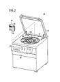
- the blood bag system 10 can be used, for example, in the state of being mounted to a centrifuging and transporting apparatus (automatic centrifugal separator) 50 as shown in FIG. 2 .
- This centrifuging and transporting apparatus 50 is used for dividing whole blood contained in the blood collection bag 12 into three layers including plasma, buffy coat and concentrated red cells, transporting the buffy coat to the BC bag 14, while transporting the plasma to the plasma bag 16, and leaving the concentrated red cells in the plasma bag 16.
- the configuration of the centrifuging and transporting apparatus 50 will be described below.
- the direction of arrows A will be referred to as the radial direction
- the direction of arrows B as the circumferential direction.
- the circumferential direction is strictly the direction along the circular arc as indicated by arrows B, but, for convenience of description, the direction orthogonal to arrows A at a location being described will also be referred to as the circumferential direction.
- the centrifuging and transporting apparatus 50 is box-like in shape, and includes an openable/closable cover 52 at the top, a centrifugal drum (centrifuging means) 53 in the inside, six unit insertion holes 54 provided at regular angular (60°) intervals inside the centrifugal drum 53, six insert units 56 inserted respectively in the unit insertion holes, and six pushers (pressing means) 66 (see FIG. 3 ) which are provided at a central region and which can each be advanced and retracted in the rotational radial direction relative to each insert unit 56.
- the centrifuging and transporting apparatus 50 is operated based on operations on a console section 62 provided at the front surface thereof, is controlled by a microcomputer (not shown), and can display predetermined information on a monitor 64.
- a central body 53a of the centrifugal drum 53 has a holding lever 67 biased by an elastic body to hold an end portion of a tube holder 80 (described later), electrodes 68, first rods 72 and second rods 74, and the pusher 66.
- the first rods 72 and the second rods 74 are driven to advance and retract in the radial direction A.
- the rods on the side of a first circumferential direction B1 constitute a first clamp driving means 76a for opening and closing the first clamp 19 (see FIG. 1 ), while the rods on the side of a second circumferential direction B2 constitute a second clamp driving means 76b for opening and closing the second clamp 21 (see FIG. 1 ).
- the part shown in FIG. 3 may be configured as a unit, and six such units may be combined in the circumferential direction.
- FIG. 4 is an exploded perspective view of the insert unit 56 as viewed from the inside diameter side (inside diameter direction A2).
- the insert unit 56 has a unit main body 58, and a cover body 60.
- the unit main body 58 is a bottomed tube which has a wide arcuate shape in top plan view and is opening at the top, wherein a small chamber (first chamber) 94 on the inside diameter side and a large chamber (second chamber) 95 on the outside diameter side are partitioned from each other by an arcuate wall 93.
- the small chamber 94 is opening not only at the top but also on the inside diameter side.
- the tube holder 80 At an upper portion on the inside diameter side of the small chamber 94, there is provided the tube holder 80 which is plate-like in shape and projecting to the inside diameter side.
- the tube holder 80 has a first guide path 82 for guiding the first tube 18, a second guide path 84 for guiding the second tube 20, and two pins 83 provided at an end portion in the outside diameter direction A1.
- Each of the first guide path 82 and the second guide path 84 has a groove shape formed by providing walls on both side along the whole length thereof and is opening on the upper side.
- the first guide path 82 extends in the inside diameter direction A2 from a nearly central part of an end portion in the outside diameter direction A1 of the tube holder 80, is bent to the first circumferential direction B1 at an intermediate part in the radial direction A, and reaches an outer end of the tube holder 80.
- a first clamp holding part 86 for holding the first clamp 19 is provided at that portion of the first guide path 82 which forms a groove along the circumferential direction B.
- the second guide path 84 extends in the inside diameter direction A2 from that part being near the center of an end portion in the outside diameter direction A1 of the tube holder 80 and being on the second circumferential direction B2 side relative to the first guide path 82, is bent to the second circumferential direction B1 at an intermediate part in the radial direction A, and reaches an outer end of the tube holder 80.
- a second clamp holding part 88 for holding the second clamp 21 is provided at that portion of the second guide path 84 which forms a groove along the circumferential direction B.
- the tube holder 80 further has a first clamp operating part 90 for operating the first clamp 19 into a closed state and an open state, and a second clamp operating part 91 for operating the second clamp 21 into a closed state and an open state.
- the cover body 60 is a cover mounted to the unit main body 58 from the outer side, can cover the outer side, the upper side and the lower side of the unit main body 58, and can securely hold the blood bag system 10 mounted to the unit main body 58.
- FIG. 5 is a schematic illustration of a condition in which the first tube 18 and the second tube 20 are held by the tube holder 80.
- a part of the blood collection bag 12 whose upper portion is fixed by the two pins 83 of the tube holder 80 is depicted by imaginary lines; besides, part of the first tube 18 and the second tube 20, the BC bag 14, and the plasma bag 16 are shown in simplified form, and the other parts of the blood bag system 10 are omitted in the drawing.
- the blood collection bag 12 is fixed at an upper portion thereof to the tube holder 80 by a method in which the two pins 83, 83 provided on the tube holder 80 are inserted in two holes 12a, 12a (see FIG. 1 ) provided in the upper portion thereof.
- the first tube 18 is mounted and held in the first guide path 82 of the tube holder 80.
- the first clamp 19 provided on the first tube 18 is held by the first clamp holding part 86.
- the BC bag 14 connected to the other end of the first tube 18 is contained in the large chamber 95 (see FIG. 4 ).
- the second tube 20 connected to the outlet of the BC bag 14 is laid around to the tube holder 80, and is mounted and held in the second guide path 84 of the tube holder 80.
- the second clamp 21 provided on the second tube 20 is held by the second clamp holding part 88.
- the plasma bag 16 connected to the other end of the second tube 20 is contained in the large chamber 95 (see FIG. 4 ).
- the third tube 40, the filter 36, the fourth tube 42 and the red cell bag 38 are omitted in FIG. 5 , they are contained in the large chamber 95.
- the blood collection tubes 22, 28, the branch tube 30 and the first flow blood bag 32 and the like are cut off after anti-leakage sealing by welding the blood collection tube 22 by a tube sealer or the like, after blood is collected into the blood collection bag 12 and before mounting the blood bag system 10 to the centrifuging and transporting apparatus 50.
- the tube holder 80 further has a sensor 97 for detecting the kind of a liquid passing inside the first tube 18 at a position on the upstream side of the first clamp 19.
- the sensor 97 includes a light casting part 98 and a light receiving part 99, and the kind of the liquid passing these parts can be determined based on the degree of light transmission through the liquid.
- a plurality of contacts (not shown) in continuity with the sensor 97 or an interface circuit thereof are provided at a lower surface of the tube holder 80, and these contacts are set in contact with the reception-side electrodes 68 (see FIG. 3 ) provided on the central body 53a of the centrifugal drum 53, whereby a signal from the sensor 97 can be supplied to the microcomputer.
- FIG. 6 is a partly omitted enlarged plan view showing a first clamp operating part 90 and the surroundings thereof.
- the first clamp 19 is a resin-made member which has a flattened C-shape as a whole, is provided at its one end with a pressing part 106 for pressing the first tube 18, is provided at its other end with a latch part 108 for engagement with the pressing part 106, is provided with a projected part 110 at a position opposed to the pressing part 106, and is provided at both sides in the longitudinal direction with holes in which the first tube 18 is inserted.
- the second clamp 21 and the other clamps also have the same structure as the first clamp 19.
- the first tube 18 With the pressing part 106 pushed in to the inner side, the first tube 18 is pinched by an inside projection of the pressing part 106 and the projected part 110, whereby the channel in the first tube 18 can be closed, and the pressing part 106 is held in the state of being engaged with the latch part 108.
- the latch part 108 When the latch part 108 is displaced toward the outer side starting from the condition where the pressing part 106 is held by the latch part 108, the latch part 108 and the pressing part 106 are disengaged from each other and the pressing part 106 is displaced toward the outer side, whereby the channel in the first tube 18 is opened.
- the first clamp operating part 90 has a first pressing body 101 which is swung by operation of the first rod 72 so as to push in the pressing part 106, and a second pressing part 102 which is swung by operation of the second rod 74 so as to tilt the latch part 108.
- the first pressing body 101 and the second pressing body 102 are rotatably supported on the tube holder 80 through shaft parts 103, 104, respectively, and are biased in a direction away from the pressing part 106 and the latch part 108 by springs (not shown); in addition, they are so configured as to be displaced toward the side of the pressing part 106 and the latch part 108 against biasing forces of the springs when pressed by the first rod 72 and the second rod 74, respectively.
- the pressing part 106 and the latch part 108 of the first clamp 19 can be operated, whereby the channel in the first tube 18 can be closed and opened.
- the second clamp operating part 91 is symmetrical in shape with the first clamp operating part 90.
- the blood bag system 10 is basically configured as above-described, and its operation and effect will be described below.
- FIG. 1 is referred to.
- the collected blood first flow is sampled into the first flow blood bag 32, as above-mentioned.
- the branch tube 30 is closed by the clamp 31, and the above-mentioned breaking operation is applied to the sealing member 24, to put the channel in the blood collection tube 22 into an open state.
- the clamp 23 is set in an open state, whereas the sealing member 17 is set in the initial state (closed state).
- the blood from the donor flows into the blood collection bag 12 by way of the blood collection tubes 28, 22.
- the blood collection tube 22 is closed by the clamp 23 so that the blood (whole blood) in the blood collection bag 12 will not flow out. Then, as above-mentioned, the blood collection tube 22 is welded and sealed by the tube sealer or the like, followed by cutting off the blood collection tube 22 at the sealed portion.
- the blood bag system 10 is mounted to the centrifuging and transporting apparatus 50.
- the channels in the first tube 18 and the second tube 20 are put into a closed state by the first clamp 19 and the second clamp 21, and thereafter the above-mentioned breaking operation is applied to the sealing member 17, to set the channel therein in an open state.
- the first tube 18 and the second tube 20 are held on the tube holder 80, and the blood collection bag 12 is contained into the small chamber 94 (see FIG. 4 ) of the unit main body 58, with its upper portion fixed on the tube holder 80.
- the part ranging from the BC bag 14, the plasma bag 16 and the third tube 40 to the red cell bag 38 is contained into the large chamber 95 (see FIG. 4 ) of the unit main body 58.
- the filter 36 and the red cell bag 38 they are not used in the centrifugation step and the subsequent separation step; therefore, it is recommendable to contain them in the large chamber 95 after making them compact by, for example, rounding or bending, whereby a space in which to contain the BC bag 14 and the plasma bag 16 can be secured.
- the insert unit 56 each with the blood bag system 10 contained therein are inserted into the unit insertion hole 54 in the centrifuging and transporting apparatus 50.
- end portions of the tube holders 80 are fixed by the holding levers 67.
- the contacts of the sensors or the interface circuits therefor are set in contact with the electrodes 68 (see FIG. 3 ).
- six insert units 56 are mounted to the centrifuging and transporting apparatus 50.
- not more than five insert units 6 preferably, three or two insert units at regular angular intervals may be mounted, insofar as they are well-balanced.
- the centrifugal drum 53 is rotated to perform the centrifugation step.
- the first clamp 19 and the second clamp 21 are preliminarily closed.
- the first rod 72 is once extended and the first clamp 19 is put into a closed state by the pressing part 106.
- the second clamp 21 is also set into a closed state.
- a centrifugal force is exerted on the whole blood stored in the blood collection bag 12 inside the small chamber 94, whereby concentrated red cell 114 as a relative high-density component is transferred to the outside diameter direction, plasma 112 as a relative low-density component is transferred to the inside diameter direction, and buffy coat 113 as a relative medium-density component is moved to an intermediate region; thus, the whole blood is separated into three layers.
- the centrifuging and transporting apparatus 50 starts the separation step after the centrifugation step.
- the first clamp driving means 76a and the second clamp driving means 76b are operated to put the channels in the first tube 18 and the second tube 20 into an open state.
- the pusher 66 is displaced in the centrifugal direction A1 to press the blood collection bag 12.
- the blood collection bag 12 is reduced in volume by being clamped between the pusher 66 and a wall, so that the liquid contained therein is discharged via the first tube 18.
- the plasma 112 located most on the inside diameter side flows out of the blood collection bag 12, and flows through the first tube 18, the BC bag 14 and the second tube 20 into the plasma bag 16.
- the buffy coat 113 After flowing of the plasma 112 out of the blood collection bag 12 is finished, the buffy coat 113 next starts flowing out of the blood collection bag 12.
- the flow of the red cells (the red cells contained in the buffy coat) in the first tube 18 is detected by the sensor 97 (see FIG. 5 )
- the channel in the second tube 20 is closed by the second clamp 21, whereby the buffy coat 113 is inhibited from flowing into the plasma bag 16.
- the fact that the red cells flow in the first tube 18 can be confirmed by the sensor 97, based on the transparency (in other words, the turbidity) of the liquid flowing in the first tube 18.
- the BC bag 14 has a structure wherein the cross-sectional area of a channel at the outlet 15 is set to be smaller than the cross-sectional area of a channel at the inlet 13.
- This setting produces a flow rate difference which ensures that a liquid accumulation of a certain amount of the plasma 112 is formed in the BC bag 14, whereby the rate of flow of liquid into the plasma bag 16 can be restrained from becoming excessively high. Therefore, although a certain time lag exists after detection of the red cells by the sensor 97 until the closing of the second tube 20 by the second clamp 21, it is possible, by suppressing the flowing-in rate into the plasma bag 16 through the provision of the flow rate difference as above-mentioned, to securely prevent the buffy coat 113 from flowing into the plasma bag 16.
- the structure of the BC bag 14 in which the cross-sectional area at the outlet 15 is set smaller than the cross-sectional area at the inlet 13 may be replaced by a structure in which the cross-sectional area of the channel in the second tube 20 is set smaller than the cross-sectional area of the channel in the first tube 18, over the whole length of or at a part of the second tube 20.
- the pusher 66 When the pusher 66 is further advanced and the blood collection bag 12 is pressed by a predetermined amount (a predetermined amount of the buffy coat in the BC bag 14 is collected), the pusher 66 is stopped, and the first clamp driving means 76a is operated to close the channel in the first tube 18 by the first clamp 19.
- the blood bag system 10 is taken out of the insert unit 56. Further, the first tube 18 and the second tube 20 in the blood bag system 10 are welded and sealed, followed by cutting, whereby each of the bags is cut off.
- a centrifugal force is exerted on the whole blood contained in the blood collection bag 12 to separate the whole blood into the three layers of the plasma 112, the buffy coat 113 and the concentrated red cells 114. Then, the blood collection bag 12 is pressed in the thickness direction thereof, whereby the plasma and the buffy coat are transported from the blood collection bag 12 to the BC bag 14 through the first tube 18, and the plasma 112 is transported from the second bag 14 to the plasma bag 16 through the second tube 20.
- the first tube 18 for transporting the plasma 112 and the buffy coat 113 from the blood collection bag 12 to the BC bag 14 and the plasma bag 16 is connected to an upper portion of the blood collection bag 12. Therefore, a tube to be connected to a lower portion of the blood collection bag 12 is unnecessary, and the tubes are connected only to the upper portion of the blood collection bag 12 in this configuration. Accordingly, the bag configuration is simplified, so that the convenience for the user in using the blood bag system 10 is enhanced. In addition, handling of the tubes in mounting the blood bag system 10 to the centrifuging and transporting apparatus 50 is facilitated, so that the mounting to the centrifuging and transporting apparatus 50 is facilitated.
- the concentrated red cells 114 left in the blood collection bag 12 leukocytes can be removed therefrom through filtration by the filter 36, and the concentrated red cells 114 freed of the leukocytes can be stored in the red cell bag 38.
- the third tube 40 through which the blood collection bag 12 and the filter 36 are connected is connected to an upper portion of the blood collection bag 12, a tube to be connected to a lower portion of the blood collection bag 12 is unnecessary.
- the blood collection bag 12 has a top-and-top (TAT) type bag structure in which the tubes are connected only to the upper portion of the bag.
- TAT top-and-top
- the BC bag 14 is used only for storing the buffy coat, and its capacity may be set according to the amount of the buffy coat to be stored therein. This permits a reduction in size of the BC bag 14, as compared with a conventional buffy coat bag. Consequently, the amount of the buffy coat left in the BC bag 14 at the time of preparing a platelet preparation by the buffy coat pooling conducted as the subsequent step can be reduced, and the platelet recovery rate can be thereby enhanced.
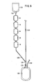
- BC pooling is a treatment wherein the contents of a plurality of BC bags 14 containing the buffy coat obtained by the above-mentioned treatment are transported and collected into a single bag.
- BC pooling a plurality of the BC bags 14 are connected in series, by use of respective tube joining devices, to a tube 126 connected to a BC pooling bag 120.
- the buffy coat obtained by the above-mentioned treatment is contained.
- a clamp 132 is in a closed state.
- a storage solution bag 123 containing a platelet storage solution is connected by use of a tube joining device. Thereafter, the storage solution bag 123 is hung from a hanger (not shown), and the clamp 132 is opened to open a channel between a branch connector 124 and the BC pooling bag 120, whereby the buffy coat is collected from the BC bags 14 into the BC pooling bag 120. In this instance, platelets are left adhering to inside walls of the BC bags 14. Therefore, the buffy coat in the BC bags 14 is washed away in the following manner.
- a breaking operation is applied to a sealing member 130 of the storage solution bag 123 to open a channel, whereby the platelet storage solution is transported into the BC bags 14, and the buffy coat remaining in the BC bags 14 is mixed with the platelet storage solution and moved into the BC pooling bag 120. Thereafter, a tube 122 is welded at a part near the BC pooling bag 120 by use of a tube sealer or the like, to be thereby sealed in a leak-free manner, and is cut.
- the BC bags 14 can be connected in parallel with each other.
- the BC bags 14 are connected respectively to a plurality of tubes branched from the tube 126, and the storage solution bags 123 are connected to the tubes 122 branched from the tube 126 by branch connectors 124, whereby BC pooling is conducted.
- the platelet storage solution is moved sequentially into the plurality of BC bags 14, so that the platelets adhering inside the BC bags 14 can be effectively washed away by a simple operation. Therefore, buffy coat recover rate is enhanced, with the result that the recovery rate of the platelets obtained by centrifugation of the buffy coat can be enhanced.
- the BC bag 14 in the blood bag system 10 is convenient for adoption of a series connection mode in BC pooling, since the BC bag 14 has a top-and-bottom (TAB) type bag structure wherein it is provided with the inlet 13 and the outlet 15 as above-mentioned.
- TAB top-and-bottom
- the BC pooling bag 120 is connected another tube 134, and to a terminal end of this tube 134 are sequentially connected a leukocyte removal filter and a platelet storage bag.
- the buffy coat in the BC pooling bag 120 is centrifugally separated into a supernatant liquid and a precipitated liquid, and the supernatant liquid thus obtained is transported to the platelet storage bag through the above-mentioned leukocyte removal filter.
- the centrifugation step and the separation step in this case may be carried out by use of the above-mentioned centrifuging and transporting apparatus 50.
- the present invention is not limited to this.
- the invention may be applied to a treatment in which blood obtained by preliminarily removing leukocytes is centrifugally separated into three components including a relative low-density component, a relative medium-density component and a relative high-density component, that is, three components including plasma (leukocyte-freed plasma), concentrated platelets (leukocyte-freed concentrated platelets) and concentrated red cells (leukocyte-freed concentrated red cells).
Landscapes
- Health & Medical Sciences (AREA)
- Heart & Thoracic Surgery (AREA)
- Vascular Medicine (AREA)
- Biomedical Technology (AREA)
- Engineering & Computer Science (AREA)
- Anesthesiology (AREA)
- Hematology (AREA)
- Life Sciences & Earth Sciences (AREA)
- Animal Behavior & Ethology (AREA)
- General Health & Medical Sciences (AREA)
- Public Health (AREA)
- Veterinary Medicine (AREA)
- Cardiology (AREA)
- Pathology (AREA)
- External Artificial Organs (AREA)
Abstract
Description
- The present invention relates to a blood bag system and a blood treatment method for centrifuging whole blood and storing individual blood components in respective bags.
- Conventionally, whole blood transfusion in which all the components of blood obtained by blood donation are put to transfusion has been the main stream. Attendant on the recent progress of technology, blood component transfusion has come to be carried out in which the blood obtained is separated into its components such as red blood cells, platelets and plasma and only the component(s) necessary for a patient is transfused into the patient. According to the blood component transfusion, burden on the patient's circulatory system and side effects can be alleviated, and effective utilization of donated blood can be contrived.
- The blood (whole blood) obtained by blood donation is centrifuged to be thereby separated into a light supernatant PPP (platelet poor plasma) fraction, a heavy precipitated CRC (concentrated red cell) fraction, and buffy coat formed therebetween. The buffy coat contains leukocytes, platelets and red cells; especially, as for platelets, the proportion of young fresh ones is high.
- In order to separate whole blood into the three blood components including platelet poor plasma, concentrated red cells and buffy coat and further to transport the blood components into predetermined storage bags, there has hitherto been used a blood bag system configured by connecting a plurality of bags by use of a plurality of tubes (see, for example,
US Patent No. 6910998 ). - One conventional example of blood bag system includes a first bag (combined buffy coat bag and whole blood bag) for storing whole blood, a first tube connected at its one end to an upper portion of the first bag, a second bag (plasma bag) which is connected to the other end of the first tube and in which platelet poor plasma is to be stored, a second tube connected at its one end to a lower portion of the first tube, and a third bag (red cell bag) which is connected to the other end of the second tube and in which concentrated red cells are to be stored. In order to preserve whole blood in the state of being separated into the blood components by use of the blood bag system configured as just-mentioned, the whole blood in the first bag is centrifuged to be separated into platelet poor plasma, concentrated red cells and buffy coat, and, thereafter, the platelet poor plasma is transported to the second bag through the first tube connected to an upper portion of the first bag, and the concentrated red cells are transported to the third bag through the second tube connected to a lower portion of the first bag.
- Incidentally, the specification of
US Patent No. 6910998 discloses a blood bag system similar to the one conventional example mentioned above. - Meanwhile, as the configuration of a centrifuging and transporting apparatus by which a step of centrifuging whole blood and a step of transporting blood components obtained by centrifugation can be performed by a single apparatus, there may be considered a configuration which includes a centrifugal drum having a plurality of unit insertion holes and driven to rotate in a circumferential direction and a plurality of insert units to be inserted in the unit insertion holes (see, for example,
US Patent No. 6910998 ). In this case, the insert unit permits the above-mentioned blood bag system to be mounted thereto. - When the above-mentioned blood bag system is supposed to be mounted to the centrifuging and transporting apparatus configured as above, there is the following problem. A first bag in the above-mentioned blood bag system has a top-and-bottom (TAB) type bag structure in which a first tube is connected to an upper portion thereof and a second tube is connected to a lower portion thereof. Therefore, in mounting the first tube to the above-mentioned insert unit, the second tube provided at the lower portion of the first bag must be laid around upward from the lower side (bottom side) of the insert unit, and the handling operation is bothersome, so that it is difficult to smoothly carry out the mounting operation. In addition, if the second tube undergoes kinking (torsion or sharp bending) due to the handling of the second tube, the second tube may be closed, possibly making it impossible to transport blood components.
- The present invention has been made in consideration of the above-mentioned circumstances. Accordingly, it is an object of the present invention to provide a blood bag system and a blood treatment method such that the blood bag system can be easily mounted to a centrifuging and transporting apparatus and the problem of kinking of a tube due to handling of the tube can be solved.
- In order to attain the above object, a blood bag system according to the present invention is characterized in that it includes: a first bag in which blood containing a plurality of components is stored; a second bag in which a relative medium-density component obtained by centrifugation of the blood in the first bag is stored; a third bag in which a relative low-density component obtained by centrifugation of the blood in the first bag is stored; a first tube through which an upper portion of the first bag and an inlet of the second bag are connected and through which the relative low-density component and the relative medium-density component are transported from the first bag to the second bag; and a second tube through which an outlet of the second bag and the third bag are connected and through which the relative low-density component is transported from the first bag to the third bag by way of the first tube and the second bag.
- According to the blood bag system of the present invention as above, blood containing a plurality of components and contained in the first bag is separated into three layers including a relative low-density component, a relative medium-density component and a relative high-density component by applying a centrifugal force to the blood, and the first bag is pressed so that the relative low-density component is transported from the first bag to the third bag through the first tube, the second bag and the second tube, whereas the relative medium-density component is transported from the first bag to the second bag through the first tube. By this operation, of the blood components centrifugally separated, the relative medium-density component is stored in the second bag, whereas the relative low-density component is stored in the third bag, and the remaining relative high-density component is stored in the first bag. Consequently, the blood can be separated into the relative low-density component, the relative medium-density component and the relative high-density components, and these components can be preserved in the respective bags. In the blood bag system according to the present invention, the first tube through which the relative medium-density component and the relative low-density component are transported from the first bag to the second bag and the third bag is connected to the upper portion of the first bag, so that a tube to be connected to a lower portion of the first bag is unnecessary, and tubes are connected only to the upper portion of the first bag in this configuration. Accordingly, the bag configuration is simplified, so that convenience for the user to use a blood bag system is enhanced. In addition, since handling of tubes in mounting the blood bag system to a centrifuging and transporting apparatus is facilitated, the mounting of the system to the centrifuging and transporting apparatus becomes easy to carry out. Besides, since the second bag is used only for storage of the relative medium-density component and its capacity may be set according to the amount of the relative medium-density component to be stored therein, the second bag can be reduced in size, as compared with a relative medium-density component bag according to the related art. Consequently, in the case where the relative medium-density component is buffy coat, it is possible to reduce the amount of buffy coat left in the second bag, and to enhance platelet recovery late, at the time of preparing a platelet preparation by buffy coat pooling conducted as a subsequent step.
- In addition, the blood bag system as above is characterized in that the second bag has a structure in which the cross-sectional area of a channel at the outlet is smaller than the cross-sectional area of a channel at the inlet.
- According to the just-mentioned configuration, the rate of flow into the third bag is suppressed, whereby the relative medium-density component can be prevented from flowing into the third bag.
- Besides, the blood bag system as above is characterized in that it includes a first clamp by which the first tube is closed and opened; and a second clamp by which the second tube is closed and opened.
- According to the just-mentioned configuration, upon detection of the transfer of a predetermined component into the first tube at the time of transporting the relative low-density component and the relative medium-density component from the first bag to the second bag, the second clamp is operated to close the second tube, whereby the predetermined component is prevented from flowing into the third bag. In addition, with the first tube closed by operating the first clamp when the first bag has been pressed by a predetermined amount, it is possible to collect a predetermined amount of a blood component into the second bag and to prevent the relative high-density component from flowing into the second bag.
- In addition, the blood bag system as above is characterized in that it includes a fourth bag in which a relative high-density component transported from the first bag is stored; a filter which is disposed between the first bag and the fourth bag and by which predetermined cells are removed; a third tube through which an upper portion of the first bag and an inlet of the filter are connected and through which the relative high-density component is transported from the first bag to the filter; and a fourth tube through which an outlet of the filter and the fourth bag are connected and through which the relative high-density component is transported from the filter to the fourth bag.
- According to the just-mentioned configuration, it is possible to filter the relative high-density component left in the first bag by a filter to thereby remove predetermined cells and to store in the fourth bag the relative high-density component freed of the predetermined cells. In addition, since the third tube interconnecting the first bag and the filter is connected to the upper portion of the first bag, a tube connected to a lower portion of the first bag is unnecessary, and tubes are connected only to the upper portion of the first bag in this configuration. Accordingly, even in the configuration in which the filter is provided, it is easy to lay around the tubes in mounting the blood bag system to a centrifuging and transporting apparatus and, hence, it is easy to mount the blood bag system to the centrifuging and transporting apparatus.
- Besides, the blood bag system as above is characterized in that the blood containing the plurality of components is whole blood, and the relative low-density component, the relative medium-density component and the relative high-density component are plasma, buffy coat and concentrated red cells, respectively.
- A blood treatment method according to the present invention is characterized in that it includes: a centrifugation step of centrifuging blood containing a plurality of components into a relative low-density component, a relative medium-density component and a relative high-density component in a first bag; and a separation step of transporting the relative low-density component from the first bag to a third bag through a first tube connected to an upper portion of the first bag and transporting the relative medium-density component from the first bag to a second bag provided between the first bag and the third bag through the first tube, by pressing the first bag.
- In addition, in the separation step, the first bag is pressed, whereby the relative low-density component and the relative medium-density component are made to flow out from the first bag through the first tube in the order of the relative low-density component and the relative medium-density component, the relative low-density component is transported from the first bag to the third bag through the second bag and a second tube connected to an outlet of the second bag, and the relative medium-density component is transported to the second bag through the first tube.
- According to the blood treatment method of the present invention as above, of the blood components centrifugally separated, the relative medium-density component is stored in the second bag, whereas the relative low-density component is stored in the third bag, and the remaining relative high-density component is stored in the first bag. In the blood bag system for use in such a blood treatment method as this, the tubes are connected only to the upper portion of the first bag. Therefore, the convenience in use of the blood bag system is enhanced through simplification of the bag configuration, and handling of the tubes at the time of mounting the blood bag system to a centrifuging and transporting apparatus is facilitated, whereby the mounting of the system to the centrifuging and transporting apparatus is facilitated. Besides, in the blood bag system for use in the blood treatment method of the present invention, the second bag can be reduced in size, as compared with a relative medium-density component bag according to the related art. In the case where the relative medium-density component is buffy coat, therefore, the amount of the buffy coat left in the second bag at the time of preparing a platelet preparation by buffy coat pooling can be reduced, and platelet recovery rate can be enhanced.
- The blood treatment method as above is characterized in that in the separation step, in transporting the relative low-density component and the relative medium-density component from the first bag to the second bag, the kind of a solution flowing through the first tube is detected, and a channel in the second tube is closed upon detection of transfer of the relative medium-density component into the first tube.
- According to the just-mentioned method, the relative medium-density component is prevented from flowing into the third bag.
- The blood treatment method as above is characterized in that in the separation step, a channel in the first tube is closed when the first bag has been pressed by a predetermined amount.
- According to the just-mentioned method, it is possible to collect a predetermined amount of a blood component into the second bag and to prevent the relative high-density component from flowing into the second bag.
- The blood treatment method as above is characterized in that it includes: a transportation step of transporting, after the separation step, the relative high-density component left in the first bag from the first bag to a filter by which predetermined cells are removed, through a third tube connected to an upper portion of the first bag, and transporting the relative high-density component passed through the filter from the filter to a fourth bag.
- Since the third tube for use in such a blood treatment method as this is connected to the upper portion of the first bag, a tube connected to a lower portion of the first bag is unnecessary, and tubes are connected only to the upper portion of the first bag in this configuration. Accordingly, even in the configuration wherein the filter is provided, it is easy to lay around the tubes at the time of mounting to a blood bag system for use in the blood treatment method to a centrifuging and transporting apparatus, and it is easy to mount the blood bag system to the centrifuging and transporting apparatus.
- In addition, the blood treatment method as above is characterized in that the blood containing the plurality of components is whole blood, and the relative low-density component, the relative medium-density component and the relative high-density component are plasma, buffy coat and concentrated red cells, respectively.
-
- [
FIG. 1 ]
FIG. 1 is a plan view of a blood bag system according to one embodiment of the present invention. - [
FIG. 2 ]
FIG. 2 is a perspective view of a centrifuging and transporting apparatus. - [
FIG. 3 ]
FIG. 3 is a partial enlarged perspective view of a centrifugal drum in the centrifuging and transporting apparatus. - [
FIG. 4 ]
FIG. 4 is an exploded perspective view of an insert unit. - [
FIG. 5 ]
FIG. 5 is a schematic illustration of a condition in which a first tube and a second tube in the blood bag system according to the one embodiment of the present invention are held by a tube holder of the centrifuging and transporting apparatus. - [
FIG. 6 ]
FIG. 6 is a partly omitted enlarged plan view showing a first clamp operating part in the blood bag system according to the one embodiment of the present invention and the surroundings thereof. - [
FIG. 7 ]
FIG. 7 is an illustration of operation of the centrifuging and transporting apparatus. - [
FIG. 8 ]
FIG. 8 is an illustration of buffy coat pooling. - Now, a
blood bag system 10 and a blood treatment method according to the present invention will be described below by showing preferred embodiments thereof and while referring to the attached drawings. -
FIG. 1 is a plan view of ablood bag system 10 according to one embodiment of the present invention. Thisblood bag system 10 is for centrifuging whole blood containing a plurality of components into three components of a relative low-density component, a relative medium-density component and a relative high-density component (in this embodiment, whole blood is centrifuged into three components including plasma, buffy coat and concentrated red cells) and containing and preserving the components separately in different bags. - As shown in
FIG. 1 , theblood bag system 10 includes: afirst bag 12 in which blood containing a plurality of components is contained; asecond bag 14 in which a relative medium-density component obtained by centrifuging the blood in thefirst bag 12 is stored; athird bag 16 in which a relative low-density component obtained by centrifuging the blood in thefirst bag 12 is contained; afirst tube 18 through which an upper portion of thefirst bag 12 and aninlet 13 of thesecond bag 14 are connected and through which the relative low-density component and the relative medium-density component are transported from thefirst bag 12 to thesecond bag 14; and asecond tube 20 by which anoutlet 15 of thesecond bag 14 and thethird bag 16 are connected and through which the relative low-density component is transported from thefirst bag 12 to thethird bag 16 by way of thefirst tube 18 and thesecond bag 14. - The
first bag 12, thesecond bag 14 and thethird bag 16 are each configured by a method in which flexible sheet materials made of a flexible resin such as polyvinyl chloride and polyolefin are placed on each other and are fused (by heat fusing or high-frequency fusing) or adhered to each other at peripheral sheet portions into a bag form. Incidentally, a firstflow blood bag 32 and ared cell bag 38 which will be described later are also configured in a bag form. - The
first bag 12 is a bag for containing (storing) blood (whole blood) collected from a donor. Hereafter, thefirst bag 12 will be referred to as the "blood collection bag." Theblood collection bag 12 is used for containing the whole blood at the time of blood collection. After the whole blood is centrifuged and buffy coat is transported to thesecond bag 14 whereas the plasma is transported to thethird bag 16 as will be described later, however, theblood collection bag 12 is used for containing and preserving the unfiltered concentrated red cells which are the remaining component. In other words, theblood collection bag 12 serves both as a whole blood containing bag and as an unfiltered concentrated red cell containing bag. - Preferably, an anticoagulant is preliminarily contained in the
blood collection bag 12. The anticoagulant is normally a solution, and examples thereof include ACD-A solution, CPD solution, CPDA-1 solution, and heparin sodium solution. The proper amount of anticoagulant is prepared corresponding to the amount of blood to be collected. - One end of a blood collection tube (proximal-side blood collection tube) 22 is connected to an upper portion of the
blood collection bag 12. Aclamp 23 by which a channel in theblood collection tube 22 is closed and opened is provided at an intermediate portion of theblood collection tube 22. One end of a sealing member (breaking communication member) 24 is connected to the other end of theblood collection tube 22. The sealingmember 24 is so configured as to close the channel in an initial condition and to open the channel by a breaking operation. - Such a sealing
member 24 as this includes a tube formed, for example, from a flexible resin such as vinyl chloride, and a tubular body which is connected to the inside of the tube in a liquid-tight manner, is closed at one end thereof and has a brittle part at a portion in the longitudinal direction thereof. To put the sealingmember 24 into an open (communicating) state, the tubular body is bent from the outside of the tube by fingers or the like to thereby break the brittle part. Consequently, a channel in the tube which has been closed by the tubular body is opened, whereby the sealingmember 24 is put into an open state. - To the other end of the sealing
member 24 is connected afirst port 26a of abranch connector 26. To asecond port 26b of thebranch connector 26 is connected one end of a blood collection tube (distal-side blood collection tube) 28, and to the other end of theblood collection tube 28 is connected ablood collection needle 29. Before use, acap 27a is being mounted to theblood collection needle 29, and, after use, aneedle guard 27b is mounted to theblood collection needle 29. Theneedle guard 27b is so disposed as to be movable along the longitudinal direction of theblood collection tube 28. - To a
third port 26c of thebranch connector 26 is connected one end of abranch tube 30. At an intermediate portion of thebranch tube 30 is provided aclamp 31 by which a channel in thebranch tube 30 is closed and opened. To the other end of thebranch tube 30 is connected to a firstflow blood bag 32. At the time of collecting blood from a donor, a first flow (collected blood first flow) of the blood collected is first contained into the firstflow blood bag 32 in a predetermined amount, before containing the blood into theblood collection bag 12. In this case, while the sealingmember 24 is kept in a closed state (initial state), theclamp 31 is put into an open state, whereby the collected blood first flow is inhibited from flowing to theblood collection tube 22 side, namely, to theblood collection bag 12 side. At the same time, the collected blood first flow can be led into the firstflow blood bag 32 through theblood collection tube 28, thebranch connector 26 and thebranch tube 30. - A
sampling port 34 is connected to the firstflow blood bag 32, and, by attaching a blood collection tube (not shown) to thesampling port 34, the collected blood first flow is sampled into the blood collection tube. The collected blood first flow thus sampled is served as blood for test. Incidentally, depending on the use, the part ranging from thebranch connector 26 to thesampling port 34 may be omitted. - The
second bag 14 is a bag in which to contain (store) buffy coat (BC). Hereafter, thesecond bag 14 will be referred to as the "BC bag." TheBC bag 14 has a bag structure of a top-and-bottom (TAB) form wherein theinlet 13 is provided at one end and theoutlet 15 is provided at the other end. TheBC bag 14 is so set as to have a necessary and sufficient capacity, taking into account the amount of buffy coat to be collected; the capacity is smaller than the capacity of theblood collection bag 12. - The
third bag 16 is a bag in which to contain (store) and preserve plasma. Hereafter, thethird bag 16 will be referred to as the "plasma bag." - The
first tube 18 is connected to an upper portion of theblood collection bag 12. In the present embodiment, a sealingmember 17 is provided at that end portion of thefirst tube 18 which is located on theblood collection bag 12 side. The sealingmember 17 has the same configuration and function as those of the above-mentioned sealingmember 24. In addition, afirst clamp 19 by which a channel in thefirst tube 18 is closed and opened is provided at an intermediate portion of thefirst tube 18. - The
second tube 20 is connected at its one end to theoutlet 15 of theBC bag 14, and is connected at its other end to theplasma bag 16. Asecond clamp 21 by which a channel in thesecond tube 20 is closed and opened is provided at an intermediate portion of thesecond tube 20. - As shown in
FIG. 1 , the blood bag system according to this embodiment further includes a fourth bag (hereafter referred to as the "red cell bag") 38 into which to contain (store) and preserve concentrated red cells transported from theblood collection bag 12, afilter 36 which is disposed between theblood collection bag 12 and thered cell bag 38 and by which predetermined cells are removed, athird tube 40 by which an upper portion of theblood collection bag 12 and an inlet of thefilter 36 are connected, and afourth tube 42 through which an outlet of thefilter 36 and thered cell bag 38 are connected. In the present embodiment, thefilter 36 is configured as a leukocyte removal filter. - A
clamp 43 by which a channel in thethird tube 40 is closed and opened is provided at an intermediate portion of thethird tube 40. Aclamp 44 by which a channel in thefourth tube 42 is closed and opened is provided at an intermediate portion of thefourth tube 42. - Incidentally, each of the tubes (inclusive of the
first tube 18 and the second tube 20) in theblood bag system 10 is a tube made of a transparent flexible resin. Each of the clamps (inclusive of thefirst clamp 19 and the second clamp 21) may be a standard product that has been used conventionally. In addition, it is recommendable to preliminarily color the clamps separately in different colors according to the locations of use thereof and the intended uses thereof. At the time of sterilization and during stock before use of theblood bag system 10, each of the clamps is in an open state and the inside of each of the bags is in a communicating and uniform sterilized state. - The
blood bag system 10 according to the present embodiment can be used, for example, in the state of being mounted to a centrifuging and transporting apparatus (automatic centrifugal separator) 50 as shown inFIG. 2 . This centrifuging and transportingapparatus 50 is used for dividing whole blood contained in theblood collection bag 12 into three layers including plasma, buffy coat and concentrated red cells, transporting the buffy coat to theBC bag 14, while transporting the plasma to theplasma bag 16, and leaving the concentrated red cells in theplasma bag 16. - For easing the understanding of the method for using the
blood bag system 10, the configuration of the centrifuging and transportingapparatus 50 will be described below. Incidentally, in the following description, the direction of arrows A will be referred to as the radial direction, and the direction of arrows B as the circumferential direction. The circumferential direction is strictly the direction along the circular arc as indicated by arrows B, but, for convenience of description, the direction orthogonal to arrows A at a location being described will also be referred to as the circumferential direction. - As shown in
FIG. 2 , the centrifuging and transportingapparatus 50 is box-like in shape, and includes an openable/closable cover 52 at the top, a centrifugal drum (centrifuging means) 53 in the inside, six unit insertion holes 54 provided at regular angular (60°) intervals inside thecentrifugal drum 53, sixinsert units 56 inserted respectively in the unit insertion holes, and six pushers (pressing means) 66 (seeFIG. 3 ) which are provided at a central region and which can each be advanced and retracted in the rotational radial direction relative to eachinsert unit 56. The centrifuging and transportingapparatus 50 is operated based on operations on aconsole section 62 provided at the front surface thereof, is controlled by a microcomputer (not shown), and can display predetermined information on amonitor 64. - As shown in
FIG. 3 , acentral body 53a of thecentrifugal drum 53 has a holdinglever 67 biased by an elastic body to hold an end portion of a tube holder 80 (described later),electrodes 68,first rods 72 andsecond rods 74, and thepusher 66. Thefirst rods 72 and thesecond rods 74, provided in two pairs, are driven to advance and retract in the radial direction A. The rods on the side of a first circumferential direction B1 constitute a first clamp driving means 76a for opening and closing the first clamp 19 (seeFIG. 1 ), while the rods on the side of a second circumferential direction B2 constitute a second clamp driving means 76b for opening and closing the second clamp 21 (seeFIG. 1 ). The part shown inFIG. 3 may be configured as a unit, and six such units may be combined in the circumferential direction. -
FIG. 4 is an exploded perspective view of theinsert unit 56 as viewed from the inside diameter side (inside diameter direction A2). As shown inFIG. 4 , theinsert unit 56 has a unitmain body 58, and acover body 60. The unitmain body 58 is a bottomed tube which has a wide arcuate shape in top plan view and is opening at the top, wherein a small chamber (first chamber) 94 on the inside diameter side and a large chamber (second chamber) 95 on the outside diameter side are partitioned from each other by anarcuate wall 93. Thesmall chamber 94 is opening not only at the top but also on the inside diameter side. At an upper portion on the inside diameter side of thesmall chamber 94, there is provided thetube holder 80 which is plate-like in shape and projecting to the inside diameter side. - The
tube holder 80 has afirst guide path 82 for guiding thefirst tube 18, asecond guide path 84 for guiding thesecond tube 20, and twopins 83 provided at an end portion in the outside diameter direction A1. Each of thefirst guide path 82 and thesecond guide path 84 has a groove shape formed by providing walls on both side along the whole length thereof and is opening on the upper side. - The
first guide path 82 extends in the inside diameter direction A2 from a nearly central part of an end portion in the outside diameter direction A1 of thetube holder 80, is bent to the first circumferential direction B1 at an intermediate part in the radial direction A, and reaches an outer end of thetube holder 80. A firstclamp holding part 86 for holding thefirst clamp 19 is provided at that portion of thefirst guide path 82 which forms a groove along the circumferential direction B. - The
second guide path 84 extends in the inside diameter direction A2 from that part being near the center of an end portion in the outside diameter direction A1 of thetube holder 80 and being on the second circumferential direction B2 side relative to thefirst guide path 82, is bent to the second circumferential direction B1 at an intermediate part in the radial direction A, and reaches an outer end of thetube holder 80. A secondclamp holding part 88 for holding thesecond clamp 21 is provided at that portion of thesecond guide path 84 which forms a groove along the circumferential direction B. - The
tube holder 80 further has a firstclamp operating part 90 for operating thefirst clamp 19 into a closed state and an open state, and a secondclamp operating part 91 for operating thesecond clamp 21 into a closed state and an open state. - The
cover body 60 is a cover mounted to the unitmain body 58 from the outer side, can cover the outer side, the upper side and the lower side of the unitmain body 58, and can securely hold theblood bag system 10 mounted to the unitmain body 58. -
FIG. 5 is a schematic illustration of a condition in which thefirst tube 18 and thesecond tube 20 are held by thetube holder 80. In addition, inFIG. 5 , for easy understanding, a part of theblood collection bag 12 whose upper portion is fixed by the twopins 83 of thetube holder 80 is depicted by imaginary lines; besides, part of thefirst tube 18 and thesecond tube 20, theBC bag 14, and theplasma bag 16 are shown in simplified form, and the other parts of theblood bag system 10 are omitted in the drawing. - As shown in
FIG. 5 , theblood collection bag 12 is fixed at an upper portion thereof to thetube holder 80 by a method in which the twopins tube holder 80 are inserted in twoholes FIG. 1 ) provided in the upper portion thereof. Thefirst tube 18 is mounted and held in thefirst guide path 82 of thetube holder 80. In addition, thefirst clamp 19 provided on thefirst tube 18 is held by the firstclamp holding part 86. - The
BC bag 14 connected to the other end of thefirst tube 18 is contained in the large chamber 95 (seeFIG. 4 ). Thesecond tube 20 connected to the outlet of theBC bag 14 is laid around to thetube holder 80, and is mounted and held in thesecond guide path 84 of thetube holder 80. Besides, thesecond clamp 21 provided on thesecond tube 20 is held by the secondclamp holding part 88. - The
plasma bag 16 connected to the other end of thesecond tube 20 is contained in the large chamber 95 (seeFIG. 4 ). Incidentally, while thethird tube 40, thefilter 36, thefourth tube 42 and thered cell bag 38 are omitted inFIG. 5 , they are contained in thelarge chamber 95. Theblood collection tubes branch tube 30 and the firstflow blood bag 32 and the like are cut off after anti-leakage sealing by welding theblood collection tube 22 by a tube sealer or the like, after blood is collected into theblood collection bag 12 and before mounting theblood bag system 10 to the centrifuging and transportingapparatus 50. - As shown in
FIG. 5 , thetube holder 80 further has asensor 97 for detecting the kind of a liquid passing inside thefirst tube 18 at a position on the upstream side of thefirst clamp 19. Thesensor 97 includes alight casting part 98 and alight receiving part 99, and the kind of the liquid passing these parts can be determined based on the degree of light transmission through the liquid. A plurality of contacts (not shown) in continuity with thesensor 97 or an interface circuit thereof are provided at a lower surface of thetube holder 80, and these contacts are set in contact with the reception-side electrodes 68 (seeFIG. 3 ) provided on thecentral body 53a of thecentrifugal drum 53, whereby a signal from thesensor 97 can be supplied to the microcomputer. -
FIG. 6 is a partly omitted enlarged plan view showing a firstclamp operating part 90 and the surroundings thereof. As shown inFIG. 6 , thefirst clamp 19 is a resin-made member which has a flattened C-shape as a whole, is provided at its one end with apressing part 106 for pressing thefirst tube 18, is provided at its other end with alatch part 108 for engagement with thepressing part 106, is provided with a projectedpart 110 at a position opposed to thepressing part 106, and is provided at both sides in the longitudinal direction with holes in which thefirst tube 18 is inserted. Thesecond clamp 21 and the other clamps also have the same structure as thefirst clamp 19. - With the
pressing part 106 pushed in to the inner side, thefirst tube 18 is pinched by an inside projection of thepressing part 106 and the projectedpart 110, whereby the channel in thefirst tube 18 can be closed, and thepressing part 106 is held in the state of being engaged with thelatch part 108. When thelatch part 108 is displaced toward the outer side starting from the condition where thepressing part 106 is held by thelatch part 108, thelatch part 108 and thepressing part 106 are disengaged from each other and thepressing part 106 is displaced toward the outer side, whereby the channel in thefirst tube 18 is opened. - As shown in
FIG. 6 , the firstclamp operating part 90 has a firstpressing body 101 which is swung by operation of thefirst rod 72 so as to push in thepressing part 106, and a secondpressing part 102 which is swung by operation of thesecond rod 74 so as to tilt thelatch part 108. The firstpressing body 101 and the secondpressing body 102 are rotatably supported on thetube holder 80 throughshaft parts pressing part 106 and thelatch part 108 by springs (not shown); in addition, they are so configured as to be displaced toward the side of thepressing part 106 and thelatch part 108 against biasing forces of the springs when pressed by thefirst rod 72 and thesecond rod 74, respectively. - In the first
clamp operating part 90 configured as above, with thefirst rod 72 and thesecond rod 74 driven to be advanced and retracted, thepressing part 106 and thelatch part 108 of thefirst clamp 19 can be operated, whereby the channel in thefirst tube 18 can be closed and opened. Incidentally, the secondclamp operating part 91 is symmetrical in shape with the firstclamp operating part 90. - The
blood bag system 10 according to the present embodiment is basically configured as above-described, and its operation and effect will be described below. - First,
FIG. 1 is referred to. At the time of collecting blood from a donor, first, the collected blood first flow is sampled into the firstflow blood bag 32, as above-mentioned. After sampling of the collected blood first flow is completed, thebranch tube 30 is closed by theclamp 31, and the above-mentioned breaking operation is applied to the sealingmember 24, to put the channel in theblood collection tube 22 into an open state. In this instance, theclamp 23 is set in an open state, whereas the sealingmember 17 is set in the initial state (closed state). As a result, the blood from the donor flows into theblood collection bag 12 by way of theblood collection tubes blood collection bag 12, theblood collection tube 22 is closed by theclamp 23 so that the blood (whole blood) in theblood collection bag 12 will not flow out. Then, as above-mentioned, theblood collection tube 22 is welded and sealed by the tube sealer or the like, followed by cutting off theblood collection tube 22 at the sealed portion. - Next, in order to separate the whole blood collected into the
blood bag system 10 into plasma, buffy coat and concentrated red cells and store them respectively in predetermined bags, theblood bag system 10 is mounted to the centrifuging and transportingapparatus 50. At the time of the mounting, first, the channels in thefirst tube 18 and thesecond tube 20 are put into a closed state by thefirst clamp 19 and thesecond clamp 21, and thereafter the above-mentioned breaking operation is applied to the sealingmember 17, to set the channel therein in an open state. - Then, as shown in
FIG. 5 , thefirst tube 18 and thesecond tube 20 are held on thetube holder 80, and theblood collection bag 12 is contained into the small chamber 94 (seeFIG. 4 ) of the unitmain body 58, with its upper portion fixed on thetube holder 80. The part ranging from theBC bag 14, theplasma bag 16 and thethird tube 40 to thered cell bag 38 is contained into the large chamber 95 (seeFIG. 4 ) of the unitmain body 58. In this case, it is recommendable to contain theBC bag 14 and theplasma bag 16 in thelarge chamber 95 in a non-bent state (seeFIG. 7 ) so that in the separation step after the centrifugation step, the buffy coat and the plasma smoothly flow respectively into theBC bag 14 and theplasma bag 16, to be stored there. As for thefilter 36 and thered cell bag 38, they are not used in the centrifugation step and the subsequent separation step; therefore, it is recommendable to contain them in thelarge chamber 95 after making them compact by, for example, rounding or bending, whereby a space in which to contain theBC bag 14 and theplasma bag 16 can be secured. After theblood bag system 10 is mounted to and contained in the unitmain body 58, thecover body 60 is mounted to the unitmain body 58, thereby putting theinsert unit 56 into an assembled state. - Subsequently, as shown in
FIG. 2 , theinsert unit 56 each with theblood bag system 10 contained therein are inserted into theunit insertion hole 54 in the centrifuging and transportingapparatus 50. As a result, end portions of thetube holders 80 are fixed by the holdinglevers 67. In addition, the contacts of the sensors or the interface circuits therefor are set in contact with the electrodes 68 (seeFIG. 3 ). Basically, sixinsert units 56 are mounted to the centrifuging and transportingapparatus 50. However, not more than five insert units 6 (preferably, three or two insert units at regular angular intervals) may be mounted, insofar as they are well-balanced. - Next, the
cover 52 of the centrifuging and transportingapparatus 50 is closed, and thereafter theconsole section 62 is operated, whereby the centrifugation step and the separation step are performed automatically. - In the automatic operation of the centrifuging and transporting
apparatus 50, first, thecentrifugal drum 53 is rotated to perform the centrifugation step. In this instance, thefirst clamp 19 and thesecond clamp 21 are preliminarily closed. For attaining further certainty, however, thefirst rod 72 is once extended and thefirst clamp 19 is put into a closed state by thepressing part 106. Thesecond clamp 21 is also set into a closed state. - In the centrifugation step, as shown in
FIG. 7 , a centrifugal force is exerted on the whole blood stored in theblood collection bag 12 inside thesmall chamber 94, whereby concentratedred cell 114 as a relative high-density component is transferred to the outside diameter direction,plasma 112 as a relative low-density component is transferred to the inside diameter direction, andbuffy coat 113 as a relative medium-density component is moved to an intermediate region; thus, the whole blood is separated into three layers. - The centrifuging and transporting
apparatus 50 starts the separation step after the centrifugation step. In the separation step, while keeping the rotation of thecentrifugal drum 53, the first clamp driving means 76a and the second clamp driving means 76b are operated to put the channels in thefirst tube 18 and thesecond tube 20 into an open state. - Subsequently, as shown in
FIG. 7 , thepusher 66 is displaced in the centrifugal direction A1 to press theblood collection bag 12. Theblood collection bag 12 is reduced in volume by being clamped between thepusher 66 and a wall, so that the liquid contained therein is discharged via thefirst tube 18. In this instance, since thefirst tube 18 is oriented to the inside diameter side, theplasma 112 located most on the inside diameter side flows out of theblood collection bag 12, and flows through thefirst tube 18, theBC bag 14 and thesecond tube 20 into theplasma bag 16. - After flowing of the
plasma 112 out of theblood collection bag 12 is finished, thebuffy coat 113 next starts flowing out of theblood collection bag 12. In this instance, when the flow of the red cells (the red cells contained in the buffy coat) in thefirst tube 18 is detected by the sensor 97 (seeFIG. 5 ), the channel in thesecond tube 20 is closed by thesecond clamp 21, whereby thebuffy coat 113 is inhibited from flowing into theplasma bag 16. Incidentally, the fact that the red cells flow in thefirst tube 18 can be confirmed by thesensor 97, based on the transparency (in other words, the turbidity) of the liquid flowing in thefirst tube 18. - As shown in
FIG. 7 , theBC bag 14 has a structure wherein the cross-sectional area of a channel at theoutlet 15 is set to be smaller than the cross-sectional area of a channel at theinlet 13. This setting produces a flow rate difference which ensures that a liquid accumulation of a certain amount of theplasma 112 is formed in theBC bag 14, whereby the rate of flow of liquid into theplasma bag 16 can be restrained from becoming excessively high. Therefore, although a certain time lag exists after detection of the red cells by thesensor 97 until the closing of thesecond tube 20 by thesecond clamp 21, it is possible, by suppressing the flowing-in rate into theplasma bag 16 through the provision of the flow rate difference as above-mentioned, to securely prevent thebuffy coat 113 from flowing into theplasma bag 16. Incidentally, the structure of theBC bag 14 in which the cross-sectional area at theoutlet 15 is set smaller than the cross-sectional area at theinlet 13 may be replaced by a structure in which the cross-sectional area of the channel in thesecond tube 20 is set smaller than the cross-sectional area of the channel in thefirst tube 18, over the whole length of or at a part of thesecond tube 20. - When the
pusher 66 is further advanced and theblood collection bag 12 is pressed by a predetermined amount (a predetermined amount of the buffy coat in theBC bag 14 is collected), thepusher 66 is stopped, and the first clamp driving means 76a is operated to close the channel in thefirst tube 18 by thefirst clamp 19. - When the separation step as above is finished, the
blood bag system 10 is taken out of theinsert unit 56. Further, thefirst tube 18 and thesecond tube 20 in theblood bag system 10 are welded and sealed, followed by cutting, whereby each of the bags is cut off. - As above-described, according to the
blood bag system 10 in the present embodiment, a centrifugal force is exerted on the whole blood contained in theblood collection bag 12 to separate the whole blood into the three layers of theplasma 112, thebuffy coat 113 and the concentratedred cells 114. Then, theblood collection bag 12 is pressed in the thickness direction thereof, whereby the plasma and the buffy coat are transported from theblood collection bag 12 to theBC bag 14 through thefirst tube 18, and theplasma 112 is transported from thesecond bag 14 to theplasma bag 16 through thesecond tube 20. This ensures that, of the blood components centrifugally separated, the buffy coat is stored in theBC bag 14, whereas theplasma 112 is stored in theplasma bag 16, and the concentratedred cells 114 as a residue are left stored in theblood collection bag 12. Consequently, the whole blood is separated into theplasma 112, thebuffy coat 113 and the concentratedred cells 114, which are separated (collected) into the respective bags. - In the
blood bag system 10 according to the present invention, thefirst tube 18 for transporting theplasma 112 and thebuffy coat 113 from theblood collection bag 12 to theBC bag 14 and theplasma bag 16 is connected to an upper portion of theblood collection bag 12. Therefore, a tube to be connected to a lower portion of theblood collection bag 12 is unnecessary, and the tubes are connected only to the upper portion of theblood collection bag 12 in this configuration. Accordingly, the bag configuration is simplified, so that the convenience for the user in using theblood bag system 10 is enhanced. In addition, handling of the tubes in mounting theblood bag system 10 to the centrifuging and transportingapparatus 50 is facilitated, so that the mounting to the centrifuging and transportingapparatus 50 is facilitated. - As for the concentrated
red cells 114 left in theblood collection bag 12, leukocytes can be removed therefrom through filtration by thefilter 36, and the concentratedred cells 114 freed of the leukocytes can be stored in thered cell bag 38. In addition, since thethird tube 40 through which theblood collection bag 12 and thefilter 36 are connected is connected to an upper portion of theblood collection bag 12, a tube to be connected to a lower portion of theblood collection bag 12 is unnecessary. Thus, theblood collection bag 12 has a top-and-top (TAT) type bag structure in which the tubes are connected only to the upper portion of the bag. Consequently, in spite of the configuration in which thefilter 36 is provided, handling of the tubes at the time of mounting theblood bag system 10 to the centrifuging and transportingapparatus 50 is easy to perform, so that the mounting to the centrifuging and transportingapparatus 50 is easy to carry out. - Besides, the
BC bag 14 is used only for storing the buffy coat, and its capacity may be set according to the amount of the buffy coat to be stored therein. This permits a reduction in size of theBC bag 14, as compared with a conventional buffy coat bag. Consequently, the amount of the buffy coat left in theBC bag 14 at the time of preparing a platelet preparation by the buffy coat pooling conducted as the subsequent step can be reduced, and the platelet recovery rate can be thereby enhanced. - Now, description will be made of "buffy coat pooling" (hereinafter referred to as BC pooling) which is a treatment wherein the contents of a plurality of
BC bags 14 containing the buffy coat obtained by the above-mentioned treatment are transported and collected into a single bag. As shown inFIG. 8 , in the BC pooling, a plurality of theBC bags 14 are connected in series, by use of respective tube joining devices, to atube 126 connected to aBC pooling bag 120. In theBC bags 14, the buffy coat obtained by the above-mentioned treatment is contained. In addition, aclamp 132 is in a closed state. - Next, to a tube of the
BC bag 14 at a terminal end, astorage solution bag 123 containing a platelet storage solution is connected by use of a tube joining device. Thereafter, thestorage solution bag 123 is hung from a hanger (not shown), and theclamp 132 is opened to open a channel between abranch connector 124 and theBC pooling bag 120, whereby the buffy coat is collected from theBC bags 14 into theBC pooling bag 120. In this instance, platelets are left adhering to inside walls of theBC bags 14. Therefore, the buffy coat in theBC bags 14 is washed away in the following manner. - A breaking operation is applied to a sealing
member 130 of thestorage solution bag 123 to open a channel, whereby the platelet storage solution is transported into theBC bags 14, and the buffy coat remaining in theBC bags 14 is mixed with the platelet storage solution and moved into theBC pooling bag 120. Thereafter, atube 122 is welded at a part near theBC pooling bag 120 by use of a tube sealer or the like, to be thereby sealed in a leak-free manner, and is cut. - Here, in the BC pooling as above-mentioned, the
BC bags 14 can be connected in parallel with each other. In that case, theBC bags 14 are connected respectively to a plurality of tubes branched from thetube 126, and thestorage solution bags 123 are connected to thetubes 122 branched from thetube 126 bybranch connectors 124, whereby BC pooling is conducted. In the case where theBC bags 14 are connected in series with each other as shown inFIG. 8 , however, the platelet storage solution is moved sequentially into the plurality ofBC bags 14, so that the platelets adhering inside theBC bags 14 can be effectively washed away by a simple operation. Therefore, buffy coat recover rate is enhanced, with the result that the recovery rate of the platelets obtained by centrifugation of the buffy coat can be enhanced. - In addition, while the plurality of
BC bags 14 must each be provided with ports at an upper portion and a lower portion thereof in order to be connected in series with each other, theBC bag 14 in theblood bag system 10 according to the present invention is convenient for adoption of a series connection mode in BC pooling, since theBC bag 14 has a top-and-bottom (TAB) type bag structure wherein it is provided with theinlet 13 and theoutlet 15 as above-mentioned. - Incidentally, to the
BC pooling bag 120 is connected anothertube 134, and to a terminal end of thistube 134 are sequentially connected a leukocyte removal filter and a platelet storage bag. After the BC pooling, the buffy coat in theBC pooling bag 120 is centrifugally separated into a supernatant liquid and a precipitated liquid, and the supernatant liquid thus obtained is transported to the platelet storage bag through the above-mentioned leukocyte removal filter. The centrifugation step and the separation step in this case may be carried out by use of the above-mentioned centrifuging and transportingapparatus 50. - While a treatment for centrifuging whole blood into three components of plasma, buffy coat and concentrated red cells has been described in the present embodiment, the present invention is not limited to this. For example, the invention may be applied to a treatment in which blood obtained by preliminarily removing leukocytes is centrifugally separated into three components including a relative low-density component, a relative medium-density component and a relative high-density component, that is, three components including plasma (leukocyte-freed plasma), concentrated platelets (leukocyte-freed concentrated platelets) and concentrated red cells (leukocyte-freed concentrated red cells).
- While the present invention has been described by showing a preferred embodiment above, the invention is not limited to the above embodiment, and various modifications are naturally possible without departure from the gist of the invention.
Claims (11)
- A blood bag system (10) comprising:a first bag (12) in which blood containing a plurality of components is stored;a second bag (14) in which a relative medium-density component obtained by centrifugation of the blood in the first bag (12) is stored;a third bag (16) in which a relative low-density component obtained by centrifugation of the blood in the first bag (12) is stored;a first tube (18) through which an upper portion of the first bag (12) and an inlet (13) of the second bag (14) are connected and through which the relative low-density component and the relative medium-density component are transported from the first bag (12) to the second bag (14); anda second tube (20) through which an outlet (15) of the second bag (14) and the third bag (16) are connected and through which the relative low-density component is transported from the first bag (12) to the third bag (16) by way of the first tube (18) and the second bag (14).
- The blood bag system (10) according to claim 1, wherein the second bag (14) has a structure in which the cross-sectional area of a channel at the outlet (15) is smaller than the cross-sectional area of a channel at the inlet (13).
- The blood bag system (10) according to claim 1, comprising:a first clamp (19) by which the first tube (18) is closed and opened; anda second clamp (21) by which the second tube (20) is closed and opened.
- The blood bag system (10) according to claim 1, comprising:a fourth bag (38) in which a relative high-density component transported from the first bag (12) is stored;a filter (36) which is disposed between the first bag (12) and the fourth bag (38) and by which predetermined cells are removed;a third tube (40) through which an upper portion of the first bag (12) and an inlet of the filter (36) are connected and through which the relative high-density component is transported from the first bag (12) to the filter (36); anda fourth tube (42) through which an outlet of the filter (36) and the fourth bag (38) are connected and through which the relative high-density component is transported from the filter (36) to the fourth bag (38).
- The blood bag system (10) according to claim 1, wherein
the blood containing the plurality of components is whole blood, and
the relative low-density component, the relative medium-density component and the relative high-density component are plasma, buffy coat and concentrated red cells, respectively. - A blood treatment method comprising:a centrifugation step of centrifuging blood containing a plurality of components into a relative low-density component, a relative medium-density component and a relative high-density component in a first bag (12); anda separation step of transporting the relative low-density component from the first bag (12) to a third bag (16) through a first tube (18) connected to an upper portion of the first bag (12) and transporting the relative medium-density component from the first bag (12) to a second bag (14) provided between the first bag (12) and the third bag (16) through the first tube (18), by pressing the first bag (12).
- The blood treatment method according to claim 6, wherein in the separation step, the first bag (12) is pressed, whereby the relative low-density component and the relative medium-density component are made to flow out from the first bag (12) through the first tube (18) in the order of the relative low-density component and the relative medium-density component, the relative low-density component is transported to the third bag (16) through the second bag (14) and a second tube (20) connected to an outlet (15) of the second bag (14), and the relative medium-density component is transported to the second bag (14) through the first tube (18).
- The blood treatment method according to claim 6, wherein in the separation step, in transporting the relative low-density component and the relative medium-density component from the first bag (12) to the second bag (14), the kind of a liquid flowing through the first tube (18) is detected, and a channel in the second tube (20) is closed upon detection of transfer of the relative medium-density component into the first tube (18).
- The blood treatment method according to claim 6, wherein in the separation step, a channel in the first tube (18) is closed when the first bag (12) has been pressed by a predetermined amount.
- The blood treatment method according to claim 6, comprising:a transportation step of transporting, after the separation step, the relative high-density component left in the first bag (12) from the first bag (12) to a filter (36) by which predetermined cells are removed, through a third tube (40) connected to an upper portion of the first bag (12), and transporting the relative high-density component passed through the filter (36) from the filter (36) to a fourth bag (38).
- The blood treatment method according to claim 6, wherein
the blood containing the plurality of components is whole blood, and
the relative low-density component, the relative medium-density component and the relative high-density component are plasma, buffy coat and concentrated red cells, respectively.
Applications Claiming Priority (2)
| Application Number | Priority Date | Filing Date | Title |
|---|---|---|---|
| JP2009257118 | 2009-11-10 | ||
| PCT/JP2010/068808 WO2011058868A1 (en) | 2009-11-10 | 2010-10-25 | Blood bag system and blood treatment method |
Publications (3)
| Publication Number | Publication Date |
|---|---|
| EP2500048A1 true EP2500048A1 (en) | 2012-09-19 |
| EP2500048A4 EP2500048A4 (en) | 2018-03-21 |
| EP2500048B1 EP2500048B1 (en) | 2023-09-27 |
Family
ID=43991528
Family Applications (1)
| Application Number | Title | Priority Date | Filing Date |
|---|---|---|---|
| EP10829828.2A Active EP2500048B1 (en) | 2009-11-10 | 2010-10-25 | Insert unit and blood bag system |
Country Status (4)
| Country | Link |
|---|---|
| US (3) | US20120289926A1 (en) |
| EP (1) | EP2500048B1 (en) |
| JP (1) | JP5695574B2 (en) |
| WO (1) | WO2011058868A1 (en) |
Cited By (3)
| Publication number | Priority date | Publication date | Assignee | Title |
|---|---|---|---|---|
| WO2015097411A1 (en) * | 2013-12-26 | 2015-07-02 | Maco Pharma | Method for extracting at least one first and one second blood component contained in a primary bag of a system of bags |
| WO2016193924A3 (en) * | 2015-06-04 | 2017-01-12 | Fondazione Irccs Ca' Granda - Ospedale Maggiore Policlinico | System of multiple bags and method for the preparation of hemocomponents |
| DE102020212609B3 (en) | 2020-10-06 | 2022-04-07 | Universität Greifswald | Process and device for the production of universal plasma |
Families Citing this family (16)
| Publication number | Priority date | Publication date | Assignee | Title |
|---|---|---|---|---|
| EP2500048B1 (en) * | 2009-11-10 | 2023-09-27 | Terumo Kabushiki Kaisha | Insert unit and blood bag system |
| WO2014102888A1 (en) * | 2012-12-24 | 2014-07-03 | テルモ株式会社 | Blood component separation device |
| US9796166B2 (en) | 2014-03-24 | 2017-10-24 | Fenwal, Inc. | Flexible biological fluid filters |
| US10376627B2 (en) | 2014-03-24 | 2019-08-13 | Fenwal, Inc. | Flexible biological fluid filters |
| US10159778B2 (en) | 2014-03-24 | 2018-12-25 | Fenwal, Inc. | Biological fluid filters having flexible walls and methods for making such filters |
| US9782707B2 (en) | 2014-03-24 | 2017-10-10 | Fenwal, Inc. | Biological fluid filters having flexible walls and methods for making such filters |
| US9968738B2 (en) | 2014-03-24 | 2018-05-15 | Fenwal, Inc. | Biological fluid filters with molded frame and methods for making such filters |
| WO2016134317A1 (en) | 2015-02-20 | 2016-08-25 | Terumo Bct, Inc. | Composite liquid bag system holder |
| US10335802B2 (en) * | 2015-03-18 | 2019-07-02 | Terumo Kabushiki Kaisha | Centrifuge and segment holder |
| EP3548108B1 (en) * | 2016-12-02 | 2024-01-31 | Terumo BCT, Inc. | Composite fluid separation |
| EP3632484B1 (en) * | 2018-10-04 | 2025-12-03 | Fenwal, Inc. | Systems for collecting samples in a photopheresis procedure |
| US12391922B2 (en) | 2019-02-15 | 2025-08-19 | Terumo Kabushiki Kaisha | Platelet lysate production method, production system, and bag set |
| DE102019109749A1 (en) | 2019-04-12 | 2020-10-15 | Lmb Technologie Gmbh | Blood separation device |
| CN114425110B (en) * | 2021-11-30 | 2025-05-27 | 刘海波 | A blood transfusion device for hematology based on artificial intelligence |
| DE102023106765A1 (en) * | 2023-03-17 | 2024-10-17 | Lmb Soft Doo Nis | blood bag handling device, blood bag handling system and blood bag handling method |
| WO2024257846A1 (en) * | 2023-06-16 | 2024-12-19 | テルモ株式会社 | Centrifugal separation system, rotating body, and centrifugal separator |
Family Cites Families (35)
| Publication number | Priority date | Publication date | Assignee | Title |
|---|---|---|---|---|
| US3064647A (en) * | 1957-06-13 | 1962-11-20 | Baxter Laboratories Inc | Blood component separation method and apparatus |
| US4767541A (en) * | 1982-06-04 | 1988-08-30 | Miles Laboratories, Inc. | Method of removing platelets and white cells from a red cell concentrate |
| AU578554B2 (en) | 1986-01-24 | 1988-10-27 | Japanese Red Cross Society | Centrifugal method of separating blood components |
| JPH0643319B2 (en) * | 1986-01-24 | 1994-06-08 | 日本赤十字社 | Blood component separation method and device thereof |
| JPS62255822A (en) | 1986-04-28 | 1987-11-07 | Japan Spectroscopic Co | Liquid level sensor |
| US5152905A (en) * | 1989-09-12 | 1992-10-06 | Pall Corporation | Method for processing blood for human transfusion |
| US5102407A (en) * | 1990-03-13 | 1992-04-07 | Miles Inc. | Blood separation system |
| US5167656A (en) * | 1991-01-22 | 1992-12-01 | Baxter International Inc. | Blood container having lay-flat sample reservoir |
| US5523004A (en) | 1992-12-04 | 1996-06-04 | Terumo Kabushiki Kaisha | Method for treatment of blood using a blood bag |
| JP3283641B2 (en) * | 1993-06-29 | 2002-05-20 | テルモ株式会社 | Blood processing method |
| DE69425966T2 (en) * | 1993-04-27 | 2001-03-29 | Haemonetics Corp., Braintree | Apheresis device |
| DE4340678C2 (en) * | 1993-11-30 | 2000-07-06 | Hettich Andreas Gmbh & Co Kg | Centrifuge for separating blood components and similar liquids |
| US5651766A (en) * | 1995-06-07 | 1997-07-29 | Transfusion Technologies Corporation | Blood collection and separation system |
| US5836934A (en) | 1995-06-07 | 1998-11-17 | Baxter International Inc. | Closed system and methods for mixing additive solutions while removing undesired matter from blood cells |
| JPH09603A (en) * | 1995-06-22 | 1997-01-07 | Nissho Corp | Blood component separation method |
| DE19712298C2 (en) * | 1997-03-24 | 1999-05-20 | Fresenius Ag | Device and method for separating blood into blood components |
| US6123859A (en) * | 1998-04-22 | 2000-09-26 | Hemasure Inc. | Method for in-line filtering biological liquid |
| US6296602B1 (en) * | 1999-03-17 | 2001-10-02 | Transfusion Technologies Corporation | Method for collecting platelets and other blood components from whole blood |
| US6364864B1 (en) | 1999-06-03 | 2002-04-02 | Baxter International Inc. | Plastic containers having inner pouches and methods for making such containers |
| JP4540768B2 (en) | 1999-09-20 | 2010-09-08 | Tdk株式会社 | Magnetic ferrite sintered body |
| DE19949109A1 (en) * | 1999-10-12 | 2001-04-19 | Mottl Link Sibylle | Production of high quality non-coagulating blood to be used for transfusions by dilution and separation without prior addition of citrates |
| JP4346201B2 (en) * | 2000-03-17 | 2009-10-21 | テルモ株式会社 | Blood component collection method |
| CN1420796A (en) * | 2000-03-31 | 2003-05-28 | 巴克斯特国际公司 | Systems and methods for collecting leukocyte-reduced blood components including blood cell-free or substantially free of blood cells |
| DE10065283A1 (en) * | 2000-12-29 | 2002-07-04 | Hettich Andreas Gmbh & Co Kg | Centrifuge with blood bag system with upper and lower outlet |
| DE10151343A1 (en) * | 2001-10-22 | 2003-05-08 | Vita 34 Ag | Bag system for the cryopreservation of body fluids |
| WO2003086640A1 (en) * | 2002-04-12 | 2003-10-23 | Gambro, Inc. | Fluid separation using a centrifuge and roller pump |
| JP2005066018A (en) * | 2003-08-25 | 2005-03-17 | Terumo Corp | Blood separator and blood separation method |
| EP2476445B1 (en) * | 2003-10-02 | 2013-10-23 | Terumo Kabushiki Kaisha | Filter unit |
| BRPI0708019A2 (en) | 2006-01-30 | 2011-05-17 | Gambro Bct Inc | ph adjustment in a whole blood sepration method |
| NL2000116C2 (en) | 2006-06-29 | 2008-01-02 | Klip Consultancy B V | Device comprising a container system for a body fluid. |
| KR100818290B1 (en) * | 2006-12-11 | 2008-03-31 | 삼성전자주식회사 | Component Separation Device and Component Separation Method |
| US7857141B2 (en) | 2006-12-11 | 2010-12-28 | Samsung Electronics Co., Ltd. | Apparatus and method for separating components |
| DE102007000310A1 (en) | 2007-06-05 | 2008-12-18 | Andreas Hettich Gmbh & Co. Kg | Insert and centrifuge with insert |
| DE102007000308A1 (en) * | 2007-06-05 | 2008-12-18 | Andreas Hettich Gmbh & Co. Kg | Insert and centrifuge with insert |
| EP2500048B1 (en) * | 2009-11-10 | 2023-09-27 | Terumo Kabushiki Kaisha | Insert unit and blood bag system |
-
2010
- 2010-10-25 EP EP10829828.2A patent/EP2500048B1/en active Active
- 2010-10-25 JP JP2011540460A patent/JP5695574B2/en active Active
- 2010-10-25 WO PCT/JP2010/068808 patent/WO2011058868A1/en not_active Ceased
-
2012
- 2012-05-09 US US13/467,813 patent/US20120289926A1/en not_active Abandoned
-
2015
- 2015-09-04 US US14/846,164 patent/US9579447B2/en active Active
-
2017
- 2017-01-19 US US15/409,959 patent/US10238781B2/en active Active
Cited By (5)
| Publication number | Priority date | Publication date | Assignee | Title |
|---|---|---|---|---|
| WO2015097411A1 (en) * | 2013-12-26 | 2015-07-02 | Maco Pharma | Method for extracting at least one first and one second blood component contained in a primary bag of a system of bags |
| FR3015902A1 (en) * | 2013-12-26 | 2015-07-03 | Maco Pharma Sa | METHOD FOR EXTRACTING AT LEAST ONE FIRST AND A SECOND BLOOD COMPONENT CONTAINED IN A PRIMARY POCKET OF A POCKET SYSTEM |
| WO2016193924A3 (en) * | 2015-06-04 | 2017-01-12 | Fondazione Irccs Ca' Granda - Ospedale Maggiore Policlinico | System of multiple bags and method for the preparation of hemocomponents |
| CN107921184A (en) * | 2015-06-04 | 2018-04-17 | 冯达泽尼艾瑞斯卡格兰达医院马乔里门诊部 | Multi-bag system and method for preparing blood components |
| DE102020212609B3 (en) | 2020-10-06 | 2022-04-07 | Universität Greifswald | Process and device for the production of universal plasma |
Also Published As
| Publication number | Publication date |
|---|---|
| US20170128643A1 (en) | 2017-05-11 |
| EP2500048A4 (en) | 2018-03-21 |
| JPWO2011058868A1 (en) | 2013-03-28 |
| US20150374899A1 (en) | 2015-12-31 |
| JP5695574B2 (en) | 2015-04-08 |
| US10238781B2 (en) | 2019-03-26 |
| US20120289926A1 (en) | 2012-11-15 |
| WO2011058868A1 (en) | 2011-05-19 |
| US9579447B2 (en) | 2017-02-28 |
| EP2500048B1 (en) | 2023-09-27 |
Similar Documents
| Publication | Publication Date | Title |
|---|---|---|
| EP2500048B1 (en) | Insert unit and blood bag system | |
| CN107029345B (en) | Clip and clip operating device | |
| US10806848B2 (en) | Composite liquid bag system holder | |
| JP6218873B2 (en) | Clamp and blood bag system | |
| EP2349395B1 (en) | Blood bag system and cassette | |
| JP2012510298A (en) | Blood bag system and cassette | |
| JP5977444B2 (en) | Blood bag system | |
| JP6943952B2 (en) | Blood bag system and blood treatment method | |
| JP2022034202A (en) | Blood bag system, centrifugal separation system and clamp |
Legal Events
| Date | Code | Title | Description |
|---|---|---|---|
| PUAI | Public reference made under article 153(3) epc to a published international application that has entered the european phase |
Free format text: ORIGINAL CODE: 0009012 |
|
| 17P | Request for examination filed |
Effective date: 20120508 |
|
| AK | Designated contracting states |
Kind code of ref document: A1 Designated state(s): AL AT BE BG CH CY CZ DE DK EE ES FI FR GB GR HR HU IE IS IT LI LT LU LV MC MK MT NL NO PL PT RO RS SE SI SK SM TR |
|
| DAX | Request for extension of the european patent (deleted) | ||
| RA4 | Supplementary search report drawn up and despatched (corrected) |
Effective date: 20180215 |
|
| RIC1 | Information provided on ipc code assigned before grant |
Ipc: A61M 1/02 20060101AFI20180210BHEP |
|
| STAA | Information on the status of an ep patent application or granted ep patent |
Free format text: STATUS: EXAMINATION IS IN PROGRESS |
|
| 17Q | First examination report despatched |
Effective date: 20191029 |
|
| GRAP | Despatch of communication of intention to grant a patent |
Free format text: ORIGINAL CODE: EPIDOSNIGR1 |
|
| STAA | Information on the status of an ep patent application or granted ep patent |
Free format text: STATUS: GRANT OF PATENT IS INTENDED |
|
| INTG | Intention to grant announced |
Effective date: 20230403 |
|
| GRAS | Grant fee paid |
Free format text: ORIGINAL CODE: EPIDOSNIGR3 |
|
| GRAA | (expected) grant |
Free format text: ORIGINAL CODE: 0009210 |
|
| STAA | Information on the status of an ep patent application or granted ep patent |
Free format text: STATUS: THE PATENT HAS BEEN GRANTED |
|
| AK | Designated contracting states |
Kind code of ref document: B1 Designated state(s): AL AT BE BG CH CY CZ DE DK EE ES FI FR GB GR HR HU IE IS IT LI LT LU LV MC MK MT NL NO PL PT RO RS SE SI SK SM TR |
|
| REG | Reference to a national code |
Ref country code: GB Ref legal event code: FG4D |
|
| REG | Reference to a national code |
Ref country code: CH Ref legal event code: EP |
|
| REG | Reference to a national code |
Ref country code: DE Ref legal event code: R096 Ref document number: 602010069059 Country of ref document: DE |
|
| REG | Reference to a national code |
Ref country code: IE Ref legal event code: FG4D |
|
| REG | Reference to a national code |
Ref country code: LT Ref legal event code: MG9D |
|
| PG25 | Lapsed in a contracting state [announced via postgrant information from national office to epo] |
Ref country code: GR Free format text: LAPSE BECAUSE OF FAILURE TO SUBMIT A TRANSLATION OF THE DESCRIPTION OR TO PAY THE FEE WITHIN THE PRESCRIBED TIME-LIMIT Effective date: 20231228 |
|
| PG25 | Lapsed in a contracting state [announced via postgrant information from national office to epo] |
Ref country code: SE Free format text: LAPSE BECAUSE OF FAILURE TO SUBMIT A TRANSLATION OF THE DESCRIPTION OR TO PAY THE FEE WITHIN THE PRESCRIBED TIME-LIMIT Effective date: 20230927 Ref country code: RS Free format text: LAPSE BECAUSE OF FAILURE TO SUBMIT A TRANSLATION OF THE DESCRIPTION OR TO PAY THE FEE WITHIN THE PRESCRIBED TIME-LIMIT Effective date: 20230927 Ref country code: NO Free format text: LAPSE BECAUSE OF FAILURE TO SUBMIT A TRANSLATION OF THE DESCRIPTION OR TO PAY THE FEE WITHIN THE PRESCRIBED TIME-LIMIT Effective date: 20231227 Ref country code: LV Free format text: LAPSE BECAUSE OF FAILURE TO SUBMIT A TRANSLATION OF THE DESCRIPTION OR TO PAY THE FEE WITHIN THE PRESCRIBED TIME-LIMIT Effective date: 20230927 Ref country code: LT Free format text: LAPSE BECAUSE OF FAILURE TO SUBMIT A TRANSLATION OF THE DESCRIPTION OR TO PAY THE FEE WITHIN THE PRESCRIBED TIME-LIMIT Effective date: 20230927 Ref country code: GR Free format text: LAPSE BECAUSE OF FAILURE TO SUBMIT A TRANSLATION OF THE DESCRIPTION OR TO PAY THE FEE WITHIN THE PRESCRIBED TIME-LIMIT Effective date: 20231228 Ref country code: FI Free format text: LAPSE BECAUSE OF FAILURE TO SUBMIT A TRANSLATION OF THE DESCRIPTION OR TO PAY THE FEE WITHIN THE PRESCRIBED TIME-LIMIT Effective date: 20230927 |
|
| REG | Reference to a national code |
Ref country code: NL Ref legal event code: MP Effective date: 20230927 |
|
| REG | Reference to a national code |
Ref country code: AT Ref legal event code: MK05 Ref document number: 1614763 Country of ref document: AT Kind code of ref document: T Effective date: 20230927 |
|
| PG25 | Lapsed in a contracting state [announced via postgrant information from national office to epo] |
Ref country code: NL Free format text: LAPSE BECAUSE OF FAILURE TO SUBMIT A TRANSLATION OF THE DESCRIPTION OR TO PAY THE FEE WITHIN THE PRESCRIBED TIME-LIMIT Effective date: 20230927 |
|
| PG25 | Lapsed in a contracting state [announced via postgrant information from national office to epo] |
Ref country code: IS Free format text: LAPSE BECAUSE OF FAILURE TO SUBMIT A TRANSLATION OF THE DESCRIPTION OR TO PAY THE FEE WITHIN THE PRESCRIBED TIME-LIMIT Effective date: 20240127 |
|
| PG25 | Lapsed in a contracting state [announced via postgrant information from national office to epo] |
Ref country code: AT Free format text: LAPSE BECAUSE OF FAILURE TO SUBMIT A TRANSLATION OF THE DESCRIPTION OR TO PAY THE FEE WITHIN THE PRESCRIBED TIME-LIMIT Effective date: 20230927 |
|
| PG25 | Lapsed in a contracting state [announced via postgrant information from national office to epo] |
Ref country code: ES Free format text: LAPSE BECAUSE OF FAILURE TO SUBMIT A TRANSLATION OF THE DESCRIPTION OR TO PAY THE FEE WITHIN THE PRESCRIBED TIME-LIMIT Effective date: 20230927 |
|
| PG25 | Lapsed in a contracting state [announced via postgrant information from national office to epo] |
Ref country code: SM Free format text: LAPSE BECAUSE OF FAILURE TO SUBMIT A TRANSLATION OF THE DESCRIPTION OR TO PAY THE FEE WITHIN THE PRESCRIBED TIME-LIMIT Effective date: 20230927 Ref country code: RO Free format text: LAPSE BECAUSE OF FAILURE TO SUBMIT A TRANSLATION OF THE DESCRIPTION OR TO PAY THE FEE WITHIN THE PRESCRIBED TIME-LIMIT Effective date: 20230927 Ref country code: IS Free format text: LAPSE BECAUSE OF FAILURE TO SUBMIT A TRANSLATION OF THE DESCRIPTION OR TO PAY THE FEE WITHIN THE PRESCRIBED TIME-LIMIT Effective date: 20240127 Ref country code: ES Free format text: LAPSE BECAUSE OF FAILURE TO SUBMIT A TRANSLATION OF THE DESCRIPTION OR TO PAY THE FEE WITHIN THE PRESCRIBED TIME-LIMIT Effective date: 20230927 Ref country code: EE Free format text: LAPSE BECAUSE OF FAILURE TO SUBMIT A TRANSLATION OF THE DESCRIPTION OR TO PAY THE FEE WITHIN THE PRESCRIBED TIME-LIMIT Effective date: 20230927 Ref country code: CZ Free format text: LAPSE BECAUSE OF FAILURE TO SUBMIT A TRANSLATION OF THE DESCRIPTION OR TO PAY THE FEE WITHIN THE PRESCRIBED TIME-LIMIT Effective date: 20230927 Ref country code: AT Free format text: LAPSE BECAUSE OF FAILURE TO SUBMIT A TRANSLATION OF THE DESCRIPTION OR TO PAY THE FEE WITHIN THE PRESCRIBED TIME-LIMIT Effective date: 20230927 Ref country code: SK Free format text: LAPSE BECAUSE OF FAILURE TO SUBMIT A TRANSLATION OF THE DESCRIPTION OR TO PAY THE FEE WITHIN THE PRESCRIBED TIME-LIMIT Effective date: 20230927 Ref country code: PT Free format text: LAPSE BECAUSE OF FAILURE TO SUBMIT A TRANSLATION OF THE DESCRIPTION OR TO PAY THE FEE WITHIN THE PRESCRIBED TIME-LIMIT Effective date: 20240129 |
|
| PG25 | Lapsed in a contracting state [announced via postgrant information from national office to epo] |
Ref country code: PL Free format text: LAPSE BECAUSE OF FAILURE TO SUBMIT A TRANSLATION OF THE DESCRIPTION OR TO PAY THE FEE WITHIN THE PRESCRIBED TIME-LIMIT Effective date: 20230927 Ref country code: IT Free format text: LAPSE BECAUSE OF FAILURE TO SUBMIT A TRANSLATION OF THE DESCRIPTION OR TO PAY THE FEE WITHIN THE PRESCRIBED TIME-LIMIT Effective date: 20230927 |
|
| REG | Reference to a national code |
Ref country code: CH Ref legal event code: PL |
|
| REG | Reference to a national code |
Ref country code: BE Ref legal event code: MM Effective date: 20231031 |
|
| PG25 | Lapsed in a contracting state [announced via postgrant information from national office to epo] |
Ref country code: LU Free format text: LAPSE BECAUSE OF NON-PAYMENT OF DUE FEES Effective date: 20231025 |
|
| PG25 | Lapsed in a contracting state [announced via postgrant information from national office to epo] |
Ref country code: LU Free format text: LAPSE BECAUSE OF NON-PAYMENT OF DUE FEES Effective date: 20231025 |
|
| REG | Reference to a national code |
Ref country code: DE Ref legal event code: R097 Ref document number: 602010069059 Country of ref document: DE |
|
| PG25 | Lapsed in a contracting state [announced via postgrant information from national office to epo] |
Ref country code: MC Free format text: LAPSE BECAUSE OF FAILURE TO SUBMIT A TRANSLATION OF THE DESCRIPTION OR TO PAY THE FEE WITHIN THE PRESCRIBED TIME-LIMIT Effective date: 20230927 |
|
| PG25 | Lapsed in a contracting state [announced via postgrant information from national office to epo] |
Ref country code: DK Free format text: LAPSE BECAUSE OF FAILURE TO SUBMIT A TRANSLATION OF THE DESCRIPTION OR TO PAY THE FEE WITHIN THE PRESCRIBED TIME-LIMIT Effective date: 20230927 |
|
| PG25 | Lapsed in a contracting state [announced via postgrant information from national office to epo] |
Ref country code: CH Free format text: LAPSE BECAUSE OF NON-PAYMENT OF DUE FEES Effective date: 20231031 |
|
| PG25 | Lapsed in a contracting state [announced via postgrant information from national office to epo] |
Ref country code: MC Free format text: LAPSE BECAUSE OF FAILURE TO SUBMIT A TRANSLATION OF THE DESCRIPTION OR TO PAY THE FEE WITHIN THE PRESCRIBED TIME-LIMIT Effective date: 20230927 Ref country code: DK Free format text: LAPSE BECAUSE OF FAILURE TO SUBMIT A TRANSLATION OF THE DESCRIPTION OR TO PAY THE FEE WITHIN THE PRESCRIBED TIME-LIMIT Effective date: 20230927 Ref country code: CH Free format text: LAPSE BECAUSE OF NON-PAYMENT OF DUE FEES Effective date: 20231031 |
|
| PLBE | No opposition filed within time limit |
Free format text: ORIGINAL CODE: 0009261 |
|
| STAA | Information on the status of an ep patent application or granted ep patent |
Free format text: STATUS: NO OPPOSITION FILED WITHIN TIME LIMIT |
|
| GBPC | Gb: european patent ceased through non-payment of renewal fee |
Effective date: 20231227 |
|
| PG25 | Lapsed in a contracting state [announced via postgrant information from national office to epo] |
Ref country code: BE Free format text: LAPSE BECAUSE OF NON-PAYMENT OF DUE FEES Effective date: 20231031 |
|
| 26N | No opposition filed |
Effective date: 20240628 |
|
| PG25 | Lapsed in a contracting state [announced via postgrant information from national office to epo] |
Ref country code: IE Free format text: LAPSE BECAUSE OF NON-PAYMENT OF DUE FEES Effective date: 20231025 |
|
| PG25 | Lapsed in a contracting state [announced via postgrant information from national office to epo] |
Ref country code: GB Free format text: LAPSE BECAUSE OF NON-PAYMENT OF DUE FEES Effective date: 20231227 |
|
| PG25 | Lapsed in a contracting state [announced via postgrant information from national office to epo] |
Ref country code: FR Free format text: LAPSE BECAUSE OF NON-PAYMENT OF DUE FEES Effective date: 20231127 |
|
| PG25 | Lapsed in a contracting state [announced via postgrant information from national office to epo] |
Ref country code: SI Free format text: LAPSE BECAUSE OF FAILURE TO SUBMIT A TRANSLATION OF THE DESCRIPTION OR TO PAY THE FEE WITHIN THE PRESCRIBED TIME-LIMIT Effective date: 20230927 |
|
| PG25 | Lapsed in a contracting state [announced via postgrant information from national office to epo] |
Ref country code: SI Free format text: LAPSE BECAUSE OF FAILURE TO SUBMIT A TRANSLATION OF THE DESCRIPTION OR TO PAY THE FEE WITHIN THE PRESCRIBED TIME-LIMIT Effective date: 20230927 Ref country code: IE Free format text: LAPSE BECAUSE OF NON-PAYMENT OF DUE FEES Effective date: 20231025 Ref country code: GB Free format text: LAPSE BECAUSE OF NON-PAYMENT OF DUE FEES Effective date: 20231227 Ref country code: FR Free format text: LAPSE BECAUSE OF NON-PAYMENT OF DUE FEES Effective date: 20231127 |
|
| PG25 | Lapsed in a contracting state [announced via postgrant information from national office to epo] |
Ref country code: BG Free format text: LAPSE BECAUSE OF FAILURE TO SUBMIT A TRANSLATION OF THE DESCRIPTION OR TO PAY THE FEE WITHIN THE PRESCRIBED TIME-LIMIT Effective date: 20230927 |
|
| PG25 | Lapsed in a contracting state [announced via postgrant information from national office to epo] |
Ref country code: BG Free format text: LAPSE BECAUSE OF FAILURE TO SUBMIT A TRANSLATION OF THE DESCRIPTION OR TO PAY THE FEE WITHIN THE PRESCRIBED TIME-LIMIT Effective date: 20230927 |
|
| REG | Reference to a national code |
Ref country code: DE Ref legal event code: R084 Ref document number: 602010069059 Country of ref document: DE |
|
| PG25 | Lapsed in a contracting state [announced via postgrant information from national office to epo] |
Ref country code: HR Free format text: LAPSE BECAUSE OF FAILURE TO SUBMIT A TRANSLATION OF THE DESCRIPTION OR TO PAY THE FEE WITHIN THE PRESCRIBED TIME-LIMIT Effective date: 20230927 |
|
| PG25 | Lapsed in a contracting state [announced via postgrant information from national office to epo] |
Ref country code: CY Free format text: LAPSE BECAUSE OF FAILURE TO SUBMIT A TRANSLATION OF THE DESCRIPTION OR TO PAY THE FEE WITHIN THE PRESCRIBED TIME-LIMIT; INVALID AB INITIO Effective date: 20101025 |
|
| PG25 | Lapsed in a contracting state [announced via postgrant information from national office to epo] |
Ref country code: HU Free format text: LAPSE BECAUSE OF FAILURE TO SUBMIT A TRANSLATION OF THE DESCRIPTION OR TO PAY THE FEE WITHIN THE PRESCRIBED TIME-LIMIT; INVALID AB INITIO Effective date: 20101025 |
|
| PG25 | Lapsed in a contracting state [announced via postgrant information from national office to epo] |
Ref country code: TR Free format text: LAPSE BECAUSE OF FAILURE TO SUBMIT A TRANSLATION OF THE DESCRIPTION OR TO PAY THE FEE WITHIN THE PRESCRIBED TIME-LIMIT Effective date: 20230927 |
|
| PGFP | Annual fee paid to national office [announced via postgrant information from national office to epo] |
Ref country code: DE Payment date: 20250902 Year of fee payment: 16 |