EP2499784B1 - Model-based virtual networking - Google Patents
Model-based virtual networking Download PDFInfo
- Publication number
- EP2499784B1 EP2499784B1 EP10830473.4A EP10830473A EP2499784B1 EP 2499784 B1 EP2499784 B1 EP 2499784B1 EP 10830473 A EP10830473 A EP 10830473A EP 2499784 B1 EP2499784 B1 EP 2499784B1
- Authority
- EP
- European Patent Office
- Prior art keywords
- connectivity
- network
- nodes
- semantics
- physical layer
- Prior art date
- Legal status (The legal status is an assumption and is not a legal conclusion. Google has not performed a legal analysis and makes no representation as to the accuracy of the status listed.)
- Active
Links
Images




Classifications
-
- H—ELECTRICITY
- H04—ELECTRIC COMMUNICATION TECHNIQUE
- H04L—TRANSMISSION OF DIGITAL INFORMATION, e.g. TELEGRAPHIC COMMUNICATION
- H04L41/00—Arrangements for maintenance, administration or management of data switching networks, e.g. of packet switching networks
- H04L41/14—Network analysis or design
- H04L41/145—Network analysis or design involving simulating, designing, planning or modelling of a network
-
- H—ELECTRICITY
- H04—ELECTRIC COMMUNICATION TECHNIQUE
- H04L—TRANSMISSION OF DIGITAL INFORMATION, e.g. TELEGRAPHIC COMMUNICATION
- H04L41/00—Arrangements for maintenance, administration or management of data switching networks, e.g. of packet switching networks
- H04L41/12—Discovery or management of network topologies
-
- H—ELECTRICITY
- H04—ELECTRIC COMMUNICATION TECHNIQUE
- H04L—TRANSMISSION OF DIGITAL INFORMATION, e.g. TELEGRAPHIC COMMUNICATION
- H04L63/00—Network architectures or network communication protocols for network security
- H04L63/10—Network architectures or network communication protocols for network security for controlling access to devices or network resources
- H04L63/102—Entity profiles
-
- H—ELECTRICITY
- H04—ELECTRIC COMMUNICATION TECHNIQUE
- H04L—TRANSMISSION OF DIGITAL INFORMATION, e.g. TELEGRAPHIC COMMUNICATION
- H04L63/00—Network architectures or network communication protocols for network security
- H04L63/20—Network architectures or network communication protocols for network security for managing network security; network security policies in general
-
- H—ELECTRICITY
- H04—ELECTRIC COMMUNICATION TECHNIQUE
- H04L—TRANSMISSION OF DIGITAL INFORMATION, e.g. TELEGRAPHIC COMMUNICATION
- H04L41/00—Arrangements for maintenance, administration or management of data switching networks, e.g. of packet switching networks
- H04L41/40—Arrangements for maintenance, administration or management of data switching networks, e.g. of packet switching networks using virtualisation of network functions or resources, e.g. SDN or NFV entities
Definitions
- Network administration is no longer a simple task.
- Large companies typically have a large presence in a single location or dispersed across several geographic locations which are interconnected via a corporate enterprise.
- the frequently changing dynamics associated with the networks involves adding/deleting employees, adding/deleting employee devices (e.g., computers, printers.), etc., and is particularly evident when dealing with complex networks that span multiple locations, or include multiple subnets, VPNs (virtual private networks), multiple routers or other network devices, such as servers, routers, gateways, switches, and so on.
- VPNs virtual private networks
- routers or other network devices such as servers, routers, gateways, switches, and so on.
- today's network management oftentimes includes a vendor-specific knowledge and data further complicating network management and administration.
- US 7 277 931 B1 relates to a user interface and a representation of connectivity.
- catalogs are formed.
- a matrix is created and displayed.
- a connection representation between pairs of elements in the catalog is formed. From this connection information, actions may be taken within the network to cause the network to instantiate the connections that are defined.
- a network administrator uses the matrix created as a basis for monitoring, problem determination, tuning and/or modeling.
- a logical connection is selected by clicking on or selecting an intersection point. This brings up a selection box that contains fields for the pertinent information. For each field, a value is selected from a catalog of possible values. After selecting values for all fields, the user has completed the configuration for the connection between the two endpoints and the configuration is stored for retrieval and/or display as desired.
- US 2008/0259790 A1 relates to techniques for resilient and reliable end-to-end connectivity in a heterogeneous network.
- the technique includes creating an instance of an abstracted network resource model (NRM) for a heterogeneous network environment of different network resource nodes.
- the technique further can include binding an application endpoint in the instance of the abstracted NRM with a connectivity endpoint for a first of the different network resource nodes.
- the technique yet further can include detecting an outage in the first of different network resource nodes.
- the technique can include re-binding the application endpoint to a second of the different network resource nodes in response to detecting the outage.
- the disclosed architecture facilitates the virtual specification of a connection between endpoints.
- a network can be defined as an abstract connectivity model expressed in terms of the connectivity intent, rather than any specific technology.
- the architecture compiles (translates) the connectivity model into configuration settings, policies, firewall rules, etc., to implement the connectivity intent based on available physical networks and devices capabilities.
- the connectivity model is used to define the connectivity semantics of a network.
- the model can be translated into a set of policies and network configuration that control the communication between the physical nodes in the physical network.
- the resultant virtual network may be a virtual overlay that is independent of the physical layer.
- the virtual overlay can also include elements and abstracts of the physical network(s).
- automatic network security rules e.g., Internet Protocol security-IPSec
- the disclosed architecture facilitates the development and implementation of a connectivity model that defines a virtual network to configure and manage a physical network.
- a physical network is defined as an abstract model, expressed in terms of the connectivity intent, rather than any specific technology.
- the connectivity model can specify virtually that computers X, Y and Z should freely communicate with each other and should also have controlled communication on particular ports with computer D.
- Translation (compiling) of the model applies the virtual network to the physical network such that configuration settings, policies, firewall rules, etc., implement the connectivity intent given available physical networks and physical devices capabilities.
- IP addresses in a specific range can be assigned to physical machines A and B.
- the connectivity semantics of connectivity model simply define that machines A and B should be able to communicate with each other.
- the connectivity model operates in terms of identities (e.g., machines and users), groups (e.g., machines and users) and other abstractions (logical model without the details of connectivity), rather than physical network addresses.
- Implementation of the desired connectivity can be accomplished by creating one or more network overlays that are independent of the physical network(s), and/or by controlling physical networks via appropriate API (application programming interface)/settings.
- the connectivity model also can be used to control IP address assignment to machines and/or users in the network overlay. For example, it is possible to allocate a specific IP address to a machine and that address will then be valid regardless of the physical network or IP address of the machine, since the assigned IP address is in the network overlay space. This capability facilitates supporting legacy applications.
- the architecture includes a mechanism for defining the connectivity model of a network or networks as a set of rules expressing connectivity intent.
- the mechanism can be a GUI (graphical user interface) editor, for example, for graphically editing the connectivity model.
- a mechanism is also included for compiling the connectivity model into configuration settings, policies, firewall rules, etc., to implement the desired connectivity model.
- the connectivity model translator can be specific to a set of networking technologies utilized by a particular implementation.
- one possible implementation can be via WindowsTM Direct AccessTM (DA) by Microsoft Corporation, where the connectivity model can be compiled into a series of IPSec, Teredo (an transmission protocol for sending IPv6 datagrams through NAT(network address translation) devices), SSTP (secure socket tunneling protocol), firewall and other settings used in an implementation.
- DA WindowsTM Direct AccessTM
- IPSec an transmission protocol for sending IPv6 datagrams through NAT(network address translation) devices
- SSTP secure socket tunneling protocol
- translators for other overlay network technology sets, such as IPv4 and IPv6, for example.
- Translators can also be created for applying the connectivity model to the physical networks by controlling programmable switches and VLANs (virtual local area networks), for example.
- the disclosed architecture also makes possible the implementation of hybrid systems, where parts of the connectivity model are supported by the network overlay(s) while other parts of the model are supported by the physical networks.
- An example of such arrangement is a blend of machines connected to a LAN which can be controlled programmatically (e.g., via VLANs, IPSec, etc.), and machines connected remotely (e.g., via Teredo or SSTP), all of which are controlled by the single connectivity model.
- the architecture also provides the mechanism for executing necessary elements of the connectivity model. This necessity administration depends on the physical implementation (e.g., overlay network versus physical network, Teredo versus SSTP versus L2TP (Layer 2 tunneling protocol) versus other protocols).
- the architecture significantly simplifies network creation, management and use by focusing on the desired connectivity (connectivity intent) rather than implementation details (e.g., IP ranges, IPSec, policies, etc.). Moreover, IT personnel no longer need to have deep networking knowledge to create or manage the network. In simple cases, such as small or medium business, and consumer applications, the complexity can be completely eliminated, allowing administrators with no networking knowledge to successfully setup and manage the network.
- simplification is provided by making the network consistent and coherent and by deriving all relevant settings, policies, etc., from the single connectivity model. All required settings/policies are guaranteed to be well aligned and nonconflicting. This is different from existing situations when each type of setting/policy/rule is defined independently, leaving room for error and inconsistencies.
- the simplification also provides high reliability by ensuring consistency and coherency, and by including built-in self-test mechanisms that verify that actual settings and connectivity are aligned with the intended connectivity model.
- Self-adjusting capabilities of the architecture allow the network to automatically switch to alternative connectivity technologies and systems (e.g., SSTP versus direct IPv6 or Teredo) to preserve the desired connectivity model while underlying network systems are changing (e.g., a portable computer moving between different networks).
- alternative connectivity technologies and systems e.g., SSTP versus direct IPv6 or Teredo
- high security can be achieved by automatically deriving network security rules (e.g., IPSec) from the connectivity model. This allows secure connectivity without spending any time to configure or manage network security.
- network security rules e.g., IPSec
- the disclosed connectivity model also allows for the creation of more complex networks and systems that use a combination of technologies with hosted systems.
- FIG. 1 illustrates a computer-implemented network management system 100 in accordance with the disclosed architecture.
- the system 100 includes an arrangement of nodes 102 of a physical network 104, and a connectivity model 106 that defines virtual connectivity between the nodes 102 using connectivity semantics 108.
- the connectivity mode is created to manage communications between the nodes 102 of the physical network 104.
- the connectivity model 106 describes a virtual network that overlays a physical layer and is independent of the physical layer.
- the connectivity model 106 describes a virtual network that overlays a physical layer and includes elements and abstracts of the physical network 104.
- the connectivity model 106 can also define network security as part of the connectivity semantics 108.
- the connectivity semantics 108 can include machine identities and user identities of the nodes, groups of nodes and groups of users and/or node identities.
- the connectivity semantics 108 manage ports and gateways of the physical network 108.
- network administration involved with a portable computer moving from one network to another network is handled seamlessly since the connectivity model indicates the groups to which the user should be connected even when mobile.
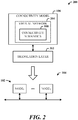
- FIG. 2 illustrates an alternative embodiment of a network management system 200 that includes a translation layer 202.
- the system 200 includes the arrangement of nodes 102 of the physical network 104 (physical layer), and the connectivity model 106 that defines virtual connectivity between the nodes 102 using connectivity semantics 108.
- the connectivity mode is created to manage communications between the nodes 102 of the physical network 104.
- the translation layer 202 translates the connectivity semantics 108 into policies and configuration information that manage the communications between the nodes 102 of the physical network 104.
- the system 200 includes the arrangement of nodes 102 of the physical network 104, the connectivity model 106 that defines virtual connectivity between the nodes 102 using the connectivity semantics 108, and the translation layer 202 that translates the connectivity semantics 108 into policies and configuration information that manage communications between the nodes 102 of the physical network 104.
- the virtual connectivity describes a virtual network 204 that overlays a physical layer and is independent of the physical layer.
- the virtual connectivity describes a virtual network 204 that overlays a physical layer and includes elements and abstracts of the physical network 104.
- the connectivity model 106 defines network security as part of the connectivity semantics 108.
- the connectivity semantics 108 include machine identities and user identities of the nodes, groups of nodes and groups of users, and/or node identities.
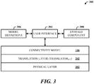
- FIG. 3 illustrates a more detailed representation of a network management system 300 in accordance with the disclosed architecture.
- the system 300 includes the connectivity model 106 (and connectivity semantics of the virtual network), which can be applied to a physical layer 302 via the translation layer 202.
- the translation layer can include one or multiple translators for translating the semantics into policies and rules, etc., for direct application to the physical layer 302.
- the system 300 also includes a user interface 304 (e.g., graphical UI) for developing and configuring the connectivity model 106 using model definitions 306.
- the definitions 306 can include a wide variety of definitions for selective deployment in different connectivity models.
- the system 300 can also include a storage component 308 for the storage of existing models for automatic or dynamic retrieval and utilization as desired. Connectivity models can be developed online or offline, and stored for later retrieval and use, on demand.
- FIG. 4 illustrates exemplary details of connectivity models 400.
- the connectivity model 106 includes the connectivity semantics 108 that can define machine and/or user IDs 402, groups 404 (of machines and/or users), and other abstractions 406.
- the semantics 108 are passed through a translator 408 specific to the connectivity model 108 (or semantic portions thereof) for translating the semantics 108 into settings, policies, and rules 410 that facilitate managing communications of a physical network 412.
- a second connectivity model 414 includes the connectivity semantics 416 that can define machine and/or user IDs 418, groups 420 (of machines and/or users), and other abstractions 422.
- the semantics 416 are passed through a translator 424 specific to the second connectivity model 414 (or semantic portions thereof) for translating the semantics 416 into settings, policies, and rules 426 that facilitate managing communications of a physical network 428.
- multiple connectivity models can be employed to configure and management corresponding physical networks, subnets of a network, physical devices (e.g., gateways, routers, etc.), and ports, for example, of physical devices and nodes, restricted only by the semantics employed and translatable in the connectivity semantics.
- one translator can be dedicated to handling IPsec policies
- a second translator can be dedicated to handling firewall policies
- a third translator is dedicated to handling SSL (secure socket layer) connections
- a fourth translator can be dedicated to handling gateways, and so on.
- the connectivity model disclosed herein provides a convenient and powerful mechanism for administrators of networks to define policies for system health requirements, such as assigning policies to groups of machines/users as facilitated by NAP (network access protection), a technology developed by Microsoft Corporation.
- the health requirements can be related to nodes having the desired version of malware detection and prevention software and an active firewall, for example.
- FIG. 5 illustrates a computer-implemented network management method.
- a connectivity model is defined that describes a virtual network of connectivity between nodes of a physical layer based on connectivity semantics.
- communications is managed between the nodes of the physical layer based on the connectivity model.
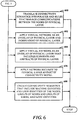
- FIG. 6 illustrates additional aspects of the method FIG. 5 .
- the connectivity semantics are translated into policies and rules that manage the communications between the nodes of the physical layer.
- the virtual network is applied as an overlay of the physical layer and independent of the physical layer.
- the virtual network is applied as an overlay of the physical layer that includes elements and abstracts of the physical layer.
- network security is applied to the physical layer as part of the connectivity model.
- connectivity semantics are created that include machine identities and user identities of the nodes, groups of nodes and groups of users, and node identities.
- a component can be, but is not limited to being, a process running on a processor, a processor, a hard disk drive, multiple storage drives (of optical, solid state, and/or magnetic storage medium), an object, an executable, a thread of execution, a program, and/or a computer.
- a component can be, but is not limited to being, a process running on a processor, a processor, a hard disk drive, multiple storage drives (of optical, solid state, and/or magnetic storage medium), an object, an executable, a thread of execution, a program, and/or a computer.
- an application running on a server and the server can be a component.
- One or more components can reside within a process and/or thread of execution, and a component can be localized on one computer and/or distributed between two or more computers.
- the word "exemplary” may be used herein to mean serving as an example, instance, or illustration. Any aspect or design described herein as "exemplary” is not necessarily to be construed as preferred or advantageous
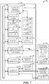
- FIG. 7 there is illustrated a block diagram of a computing system 700 operable to develop, translate, and implement a connectivity model in accordance with the disclosed architecture.
- FIG. 7 and the following description are intended to provide a brief, general description of the suitable computing system 700 in which the various aspects can be implemented. While the description above is in the general context of computer-executable instructions that can run on one or more computers, those skilled in the art will recognize that a novel embodiment also can be implemented in combination with other program modules and/or as a combination of hardware and software.
- the computing system 700 for implementing various aspects includes the computer 702 having processing unit(s) 704, a computer-readable storage such as a system memory 706, and a system bus 708.
- the processing unit(s) 704 can be any of various commercially available processors such as single-processor, multi-processor, single-core units and multi-core units.
- processors such as single-processor, multi-processor, single-core units and multi-core units.
- those skilled in the art will appreciate that the novel methods can be practiced with other computer system configurations, including minicomputers, mainframe computers, as well as personal computers (e.g., desktop, laptop, etc.), hand-held computing devices, microprocessor-based or programmable consumer electronics, and the like, each of which can be operatively coupled to one or more associated devices.
- the system memory 706 can include computer-readable storage such as a volatile (VOL) memory 710 (e.g., random access memory (RAM)) and non-volatile memory (NON-VOL) 712 (e.g., ROM, EPROM, EEPROM, etc.).
- VOL volatile
- NON-VOL non-volatile memory
- BIOS basic input/output system
- the volatile memory 710 can also include a high-speed RAM such as static RAM for caching data.
- the system bus 708 provides an interface for system components including, but not limited to, the memory subsystem 706 to the processing unit(s) 704.
- the system bus 708 can be any of several types of bus structure that can further interconnect to a memory bus (with or without a memory controller), and a peripheral bus (e.g., PCI, PCIe, AGP, LPC, etc.), using any of a variety of commercially available bus architectures.
- the computer 702 further includes machine readable storage subsystem(s) 714 and storage interface(s) 716 for interfacing the storage subsystem(s) 714 to the system bus 708 and other desired computer components.
- the storage subsystem(s) 714 can include one or more of a hard disk drive (HDD), a magnetic floppy disk drive (FDD), and/or optical disk storage drive (e.g., a CD-ROM drive DVD drive), for example.
- the storage interface(s) 716 can include interface technologies such as EIDE, ATA, SATA, and IEEE 1394, for example.
- One or more programs and data can be stored in the memory subsystem 706, a machine readable and removable memory subsystem 718 (e.g., flash drive form factor technology), and/or the storage subsystem(s) 714 (e.g., optical, magnetic, solid state), including an operating system 720, one or more application programs 722, other program modules 724, and program data 726.
- a machine readable and removable memory subsystem 718 e.g., flash drive form factor technology
- the storage subsystem(s) 714 e.g., optical, magnetic, solid state
- an operating system 720 e.g., one or more application programs 722, other program modules 724, and program data 726.
- the one or more application programs 722, other program modules 724, and program data 726 can include the connectivity model and connectivity semantics described herein, the translation layer and translators, the system 300 of FIG. 3 , models 400 and associated entities of FIG. 4 , and the methods represented by the flow charts of Figures 5-6 , for example.
- programs include routines, methods, data structures, other software components, etc., that perform particular tasks or implement particular abstract data types. All or portions of the operating system 720, applications 722, modules 724, and/or data 726 can also be cached in memory such as the volatile memory 710, for example. It is to be appreciated that the disclosed architecture can be implemented with various commercially available operating systems or combinations of operating systems (e.g., as virtual machines).
- the storage subsystem(s) 714 and memory subsystems (706 and 718) serve as computer readable media for volatile and non-volatile storage of data, data structures, computer-executable instructions, and so forth.
- Computer readable media can be any available media that can be accessed by the computer 702 and includes volatile and non-volatile internal and/or external media that is removable or non-removable.
- the media accommodate the storage of data in any suitable digital format. It should be appreciated by those skilled in the art that other types of computer readable media can be employed such as zip drives, magnetic tape, flash memory cards, flash drives, cartridges, and the like, for storing computer executable instructions for performing the novel methods of the disclosed architecture.
- a user can interact with the computer 702, programs, and data using external user input devices 728 such as a keyboard and a mouse.
- Other external user input devices 728 can include a microphone, an IR (infrared) remote control, a joystick, a game pad, camera recognition systems, a stylus pen, touch screen, gesture systems (e.g., eye movement, head movement, etc.), and/or the like.
- the user can interact with the computer 702, programs, and data using onboard user input devices 730 such a touchpad, microphone, keyboard, etc., where the computer 702 is a portable computer, for example.
- I/O device interface(s) 732 are connected to the processing unit(s) 704 through input/output (I/O) device interface(s) 732 via the system bus 708, but can be connected by other interfaces such as a parallel port, IEEE 1394 serial port, a game port, a USB port, an IR interface, etc.
- the I/O device interface(s) 732 also facilitate the use of output peripherals 734 such as printers, audio devices, camera devices, and so on, such as a sound card and/or onboard audio processing capability.
- One or more graphics interface(s) 736 (also commonly referred to as a graphics processing unit (GPU)) provide graphics and video signals between the computer 702 and external display(s) 738 (e.g., LCD, plasma) and/or onboard displays 740 (e.g., for portable computer).
- graphics interface(s) 736 can also be manufactured as part of the computer system board.
- the computer 702 can operate in a networked environment (e.g., IP-based) using logical connections via a wired/wireless communications subsystem 742 to one or more networks and/or other computers.
- the other computers can include workstations, servers, routers, personal computers, microprocessor-based entertainment appliances, peer devices or other common network nodes, and typically include many or all of the elements described relative to the computer 702.
- the logical connections can include wired/wireless connectivity to a local area network (LAN), a wide area network (WAN), hotspot, and so on.
- LAN and WAN networking environments are commonplace in offices and companies and facilitate enterprise-wide computer networks, such as intranets, all of which may connect to a global communications network such as the Internet.
- the computer 702 When used in a networking environment the computer 702 connects to the network via a wired/wireless communication subsystem 742 (e.g., a network interface adapter, onboard transceiver subsystem, etc.) to communicate with wired/wireless networks, wired/wireless printers, wired/wireless input devices 744, and so on.
- the computer 702 can include a modem or other means for establishing communications over the network.
- programs and data relative to the computer 702 can be stored in the remote memory/storage device, as is associated with a distributed system. It will be appreciated that the network connections shown are exemplary and other means of establishing a communications link between the computers can be used.
- the computer 702 is operable to communicate with wired/wireless devices or entities using the radio technologies such as the IEEE 802.xx family of standards, such as wireless devices operatively disposed in wireless communication (e.g., IEEE 802.11 over-the-air modulation techniques) with, for example, a printer, scanner, desktop and/or portable computer, personal digital assistant (PDA), communications satellite, any piece of equipment or location associated with a wirelessly detectable tag (e.g., a kiosk, news stand, restroom), and telephone.
- PDA personal digital assistant
- the communications can be a predefined structure as with a conventional network or simply an ad hoc communication between at least two devices.
- Wi-Fi networks use radio technologies called IEEE 802.11x (a, b, g, etc.) to provide secure, reliable, fast wireless connectivity.
- IEEE 802.11x a, b, g, etc.
- a Wi-Fi network can be used to connect computers to each other, to the Internet, and to wire networks (which use IEEE 802.3-related media and functions).
- the illustrated aspects can also be practiced in distributed computing environments where certain tasks are performed by remote processing devices that are linked through a communications network.
- program modules can be located in local and/or remote storage and/or memory system.
- the environment 800 includes one or more client(s) 802.
- the client(s) 802 can be hardware and/or software (e.g., threads, processes, computing devices).
- the client(s) 802 can house cookie(s) and/or associated contextual information, for example.
- the environment 800 also includes one or more server(s) 804.
- the server(s) 804 can also be hardware and/or software (e.g., threads, processes, computing devices).
- the servers 804 can house threads to perform transformations by employing the architecture, for example.
- One possible communication between a client 802 and a server 804 can be in the form of a data packet adapted to be transmitted between two or more computer processes.
- the data packet may include a cookie and/or associated contextual information, for example.
- the environment 800 includes a communication framework 806 (e.g., a global communication network such as the Internet) that can be employed to facilitate communications between the client(s) 802 and the server(s) 804.
- a communication framework 806 e.g., a global communication network such as the Internet
- Communications can be facilitated via a wire (including optical fiber) and/or wireless technology.
- the client(s) 802 are operatively connected to one or more client data store(s) 808 that can be employed to store information local to the client(s) 802 (e.g., cookie(s) and/or associated contextual information).
- the server(s) 804 are operatively connected to one or more server data store(s) 810 that can be employed to store information local to the servers 804.
Landscapes
- Engineering & Computer Science (AREA)
- Computer Networks & Wireless Communication (AREA)
- Signal Processing (AREA)
- Computer Security & Cryptography (AREA)
- Computer Hardware Design (AREA)
- Computing Systems (AREA)
- General Engineering & Computer Science (AREA)
- Data Exchanges In Wide-Area Networks (AREA)
- Computer And Data Communications (AREA)
Description
- Network administration is no longer a simple task. Large companies typically have a large presence in a single location or dispersed across several geographic locations which are interconnected via a corporate enterprise. With such large and complex deployments, the frequently changing dynamics associated with the networks involves adding/deleting employees, adding/deleting employee devices (e.g., computers, printers.), etc., and is particularly evident when dealing with complex networks that span multiple locations, or include multiple subnets, VPNs (virtual private networks), multiple routers or other network devices, such as servers, routers, gateways, switches, and so on. Moreover, today's network management oftentimes includes a vendor-specific knowledge and data further complicating network management and administration.
-
US 7 277 931 B1 relates to a user interface and a representation of connectivity. In an example, catalogs are formed. A matrix is created and displayed. A connection representation between pairs of elements in the catalog is formed. From this connection information, actions may be taken within the network to cause the network to instantiate the connections that are defined. A network administrator uses the matrix created as a basis for monitoring, problem determination, tuning and/or modeling. In an example, a logical connection is selected by clicking on or selecting an intersection point. This brings up a selection box that contains fields for the pertinent information. For each field, a value is selected from a catalog of possible values. After selecting values for all fields, the user has completed the configuration for the connection between the two endpoints and the configuration is stored for retrieval and/or display as desired. -
US 2008/0259790 A1 relates to techniques for resilient and reliable end-to-end connectivity in a heterogeneous network. In an example, the technique includes creating an instance of an abstracted network resource model (NRM) for a heterogeneous network environment of different network resource nodes. The technique further can include binding an application endpoint in the instance of the abstracted NRM with a connectivity endpoint for a first of the different network resource nodes. The technique yet further can include detecting an outage in the first of different network resource nodes. Finally, the technique can include re-binding the application endpoint to a second of the different network resource nodes in response to detecting the outage. - It is the object of the present invention to simplify the task of administering a network architecture. This object is solved by the subject matter of the independent claims. Preferred embodiments are defined by the dependent claims.
- The following presents a simplified summary in order to provide a basic understanding of some novel embodiments described herein. This summary is not an extensive overview, and it is not intended to identify key/critical elements or to delineate the scope thereof. Its sole purpose is to present some concepts in a simplified form as a prelude to the more detailed description that is presented later.
- The disclosed architecture facilitates the virtual specification of a connection between endpoints. A network can be defined as an abstract connectivity model expressed in terms of the connectivity intent, rather than any specific technology. The architecture compiles (translates) the connectivity model into configuration settings, policies, firewall rules, etc., to implement the connectivity intent based on available physical networks and devices capabilities.
- The connectivity model is used to define the connectivity semantics of a network. The model can be translated into a set of policies and network configuration that control the communication between the physical nodes in the physical network. The resultant virtual network may be a virtual overlay that is independent of the physical layer. Alternatively, the virtual overlay can also include elements and abstracts of the physical network(s). Moreover, automatic network security rules (e.g., Internet Protocol security-IPSec) can be derived from the connectivity model of the network.
- To the accomplishment of the foregoing and related ends, certain illustrative aspects are described herein in connection with the following description and the annexed
drawings. These aspects are indicative of the various ways in which the principles disclosed herein can be practiced and all aspects and equivalents thereof are intended to be within the scope of the claimed subject matter. Other advantages and novel features will become apparent from the following detailed description when considered in conjunction with the drawings. -
-
FIG. 1 illustrates a computer-implemented network management system in accordance with the disclosed architecture. -
FIG. 2 illustrates an alternative embodiment of a network management system that includes a translation layer. -
FIG. 3 illustrates a more detailed representation of a network management system in accordance with the disclosed architecture. -
FIG. 4 illustrates exemplary details of connectivity models. -
FIG. 5 illustrates a computer-implemented network management method. -
FIG. 6 illustrates additional aspects of the methodFIG. 5 . -
FIG. 7 illustrates a block diagram of a computing system operable to develop, translate, and implement a connectivity model in accordance with the disclosed architecture. -
FIG. 8 illustrates a schematic block diagram of a computing environment that for development, translation, and implementation of a connectivity model. - The disclosed architecture facilitates the development and implementation of a connectivity model that defines a virtual network to configure and manage a physical network. In other words, a physical network is defined as an abstract model, expressed in terms of the connectivity intent, rather than any specific technology. For example, the connectivity model can specify virtually that computers X, Y and Z should freely communicate with each other and should also have controlled communication on particular ports with computer D. Translation (compiling) of the model applies the virtual network to the physical network such that configuration settings, policies, firewall rules, etc., implement the connectivity intent given available physical networks and physical devices capabilities.
- For example, IP addresses in a specific range can be assigned to physical machines A and B. Rather than specifically calling out the routing between appropriate subnets, as represented in the existing techniques for configuring the physical network, the connectivity semantics of connectivity model simply define that machines A and B should be able to communicate with each other.
- The connectivity model operates in terms of identities (e.g., machines and users), groups (e.g., machines and users) and other abstractions (logical model without the details of connectivity), rather than physical network addresses.
- Implementation of the desired connectivity can be accomplished by creating one or more network overlays that are independent of the physical network(s), and/or by controlling physical networks via appropriate API (application programming interface)/settings. In configurations that use network overlays, the connectivity model also can be used to control IP address assignment to machines and/or users in the network overlay. For example, it is possible to allocate a specific IP address to a machine and that address will then be valid regardless of the physical network or IP address of the machine, since the assigned IP address is in the network overlay space. This capability facilitates supporting legacy applications.
- The architecture includes a mechanism for defining the connectivity model of a network or networks as a set of rules expressing connectivity intent. The mechanism can be a GUI (graphical user interface) editor, for example, for graphically editing the connectivity model. A mechanism is also included for compiling the connectivity model into configuration settings, policies, firewall rules, etc., to implement the desired connectivity model.
- The connectivity model translator (compiler) can be specific to a set of networking technologies utilized by a particular implementation. For example, one possible implementation can be via Windows™ Direct Access™ (DA) by Microsoft Corporation, where the connectivity model can be compiled into a series of IPSec, Teredo (an transmission protocol for sending IPv6 datagrams through NAT(network address translation) devices), SSTP (secure socket tunneling protocol), firewall and other settings used in an implementation.
- It is possible to create translators for other overlay network technology sets, such as IPv4 and IPv6, for example. Translators (compilers) can also be created for applying the connectivity model to the physical networks by controlling programmable switches and VLANs (virtual local area networks), for example.
- The disclosed architecture also makes possible the implementation of hybrid systems, where parts of the connectivity model are supported by the network overlay(s) while other parts of the model are supported by the physical networks. An example of such arrangement is a blend of machines connected to a LAN which can be controlled programmatically (e.g., via VLANs, IPSec, etc.), and machines connected remotely (e.g., via Teredo or SSTP), all of which are controlled by the single connectivity model.
- The architecture also provides the mechanism for executing necessary elements of the connectivity model. This necessity administration depends on the physical implementation (e.g., overlay network versus physical network, Teredo versus SSTP versus L2TP (
Layer 2 tunneling protocol) versus other protocols). - The architecture significantly simplifies network creation, management and use by focusing on the desired connectivity (connectivity intent) rather than implementation details (e.g., IP ranges, IPSec, policies, etc.). Moreover, IT personnel no longer need to have deep networking knowledge to create or manage the network. In simple cases, such as small or medium business, and consumer applications, the complexity can be completely eliminated, allowing administrators with no networking knowledge to successfully setup and manage the network.
- Additionally, simplification is provided by making the network consistent and coherent and by deriving all relevant settings, policies, etc., from the single connectivity model. All required settings/policies are guaranteed to be well aligned and nonconflicting. This is different from existing situations when each type of setting/policy/rule is defined independently, leaving room for error and inconsistencies.
- The simplification also provides high reliability by ensuring consistency and coherency, and by including built-in self-test mechanisms that verify that actual settings and connectivity are aligned with the intended connectivity model.
- Self-adjusting capabilities of the architecture allow the network to automatically switch to alternative connectivity technologies and systems (e.g., SSTP versus direct IPv6 or Teredo) to preserve the desired connectivity model while underlying network systems are changing (e.g., a portable computer moving between different networks).
- Additionally, high security can be achieved by automatically deriving network security rules (e.g., IPSec) from the connectivity model. This allows secure connectivity without spending any time to configure or manage network security.
- The disclosed connectivity model also allows for the creation of more complex networks and systems that use a combination of technologies with hosted systems.
- Reference is now made to the drawings, wherein like reference numerals are used to refer to like elements throughout. In the following description, for purposes of explanation, numerous specific details are set forth in order to provide a thorough understanding thereof. It may be evident, however, that the novel embodiments can be practiced without these specific details. In other instances, well known structures and devices are shown in block diagram form in order to facilitate a description thereof. The intention is to cover all modifications, equivalents, and alternatives falling within the scope of the claimed subject matter.
-
FIG. 1 illustrates a computer-implementednetwork management system 100 in accordance with the disclosed architecture. Thesystem 100 includes an arrangement ofnodes 102 of aphysical network 104, and aconnectivity model 106 that defines virtual connectivity between thenodes 102 usingconnectivity semantics 108. The connectivity mode is created to manage communications between thenodes 102 of thephysical network 104. - The
connectivity model 106 describes a virtual network that overlays a physical layer and is independent of the physical layer. Theconnectivity model 106 describes a virtual network that overlays a physical layer and includes elements and abstracts of thephysical network 104. Theconnectivity model 106 can also define network security as part of theconnectivity semantics 108. Theconnectivity semantics 108 can include machine identities and user identities of the nodes, groups of nodes and groups of users and/or node identities. Theconnectivity semantics 108 manage ports and gateways of thephysical network 108. - Thus, network administration involved with a portable computer moving from one network to another network (e.g., across corporate geographic locations) is handled seamlessly since the connectivity model indicates the groups to which the user should be connected even when mobile.
-
FIG. 2 illustrates an alternative embodiment of anetwork management system 200 that includes atranslation layer 202. Thesystem 200 includes the arrangement ofnodes 102 of the physical network 104 (physical layer), and theconnectivity model 106 that defines virtual connectivity between thenodes 102 usingconnectivity semantics 108. The connectivity mode is created to manage communications between thenodes 102 of thephysical network 104. Thetranslation layer 202 translates theconnectivity semantics 108 into policies and configuration information that manage the communications between thenodes 102 of thephysical network 104. - Put another way, the
system 200 includes the arrangement ofnodes 102 of thephysical network 104, theconnectivity model 106 that defines virtual connectivity between thenodes 102 using theconnectivity semantics 108, and thetranslation layer 202
that translates theconnectivity semantics 108 into policies and configuration information that manage communications between thenodes 102 of thephysical network 104. - The virtual connectivity describes a
virtual network 204 that overlays a physical layer and is independent of the physical layer. The virtual connectivity describes avirtual network 204 that overlays a physical layer and includes elements and abstracts of thephysical network 104. Theconnectivity model 106 defines network security as part of theconnectivity semantics 108. Theconnectivity semantics 108 include machine identities and user identities of the nodes, groups of nodes and groups of users, and/or node identities. -
FIG. 3 illustrates a more detailed representation of anetwork management system 300 in accordance with the disclosed architecture. Thesystem 300 includes the connectivity model 106 (and connectivity semantics of the virtual network), which can be applied to aphysical layer 302 via thetranslation layer 202. The translation layer can include one or multiple translators for translating the semantics into policies and rules, etc., for direct application to thephysical layer 302. - The
system 300 also includes a user interface 304 (e.g., graphical UI) for developing and configuring theconnectivity model 106 usingmodel definitions 306. Thedefinitions 306 can include a wide variety of definitions for selective deployment in different connectivity models. Thesystem 300 can also include astorage component 308 for the storage of existing models for automatic or dynamic retrieval and utilization as desired. Connectivity models can be developed online or offline, and stored for later retrieval and use, on demand. -
FIG. 4 illustrates exemplary details ofconnectivity models 400. Here, theconnectivity model 106 includes theconnectivity semantics 108 that can define machine and/oruser IDs 402, groups 404 (of machines and/or users), andother abstractions 406. Thesemantics 108 are passed through atranslator 408 specific to the connectivity model 108 (or semantic portions thereof) for translating thesemantics 108 into settings, policies, and rules 410 that facilitate managing communications of aphysical network 412. - Similarly, a
second connectivity model 414 includes theconnectivity semantics 416 that can define machine and/oruser IDs 418, groups 420 (of machines and/or users), andother abstractions 422. Thesemantics 416 are passed through atranslator 424 specific to the second connectivity model 414 (or semantic portions thereof) for translating thesemantics 416 into settings, policies, and rules 426 that facilitate managing communications of aphysical network 428. - In other words, multiple connectivity models can be employed to configure and management corresponding physical networks, subnets of a network, physical devices (e.g., gateways, routers, etc.), and ports, for example, of physical devices and nodes, restricted only by the semantics employed and translatable in the connectivity semantics. With respect to the multiple translators, one translator can be dedicated to handling IPsec policies, a second translator can be dedicated to handling firewall policies, a third translator is dedicated to handling SSL (secure socket layer) connections, a fourth translator can be dedicated to handling gateways, and so on.
- The connectivity model disclosed herein provides a convenient and powerful mechanism for administrators of networks to define policies for system health requirements, such as assigning policies to groups of machines/users as facilitated by NAP (network access protection), a technology developed by Microsoft Corporation. The health requirements can be related to nodes having the desired version of malware detection and prevention software and an active firewall, for example.
- Included herein is a set of flow charts representative of exemplary methodologies for performing novel aspects of the disclosed architecture. While, for purposes of simplicity of explanation, the one or more methodologies shown herein, for example, in the form of a flow chart or flow diagram, are shown and described as a series of acts, it is to be understood and appreciated that the methodologies are not limited by the order of acts, as some acts may, in accordance therewith, occur in a different order and/or concurrently with other acts from that shown and described herein. For example, those skilled in the art will understand and appreciate that a methodology could alternatively be represented as a series of interrelated states or events, such as in a state diagram. Moreover, not all acts illustrated in a methodology may be required for a novel implementation.
-
FIG. 5 illustrates a computer-implemented network management method. At 500, a connectivity model is defined that describes a virtual network of connectivity between nodes of a physical layer based on connectivity semantics. At 502, communications is managed between the nodes of the physical layer based on the connectivity model. -
FIG. 6 illustrates additional aspects of the methodFIG. 5 . At 600, the connectivity semantics are translated into policies and rules that manage the communications between the nodes of the physical layer. At 602, the virtual network is applied as an overlay of the physical layer and independent of the physical layer. At 604, the virtual network is applied as an overlay of the physical layer that includes elements and abstracts of the physical layer. At 606, network security is applied to the physical layer as part of the connectivity model. At 608, connectivity semantics are created that include machine identities and user identities of the nodes, groups of nodes and groups of users, and node identities. - As used in this application, the terms "component" and "system" are intended to refer to a computer-related entity, either hardware, a combination of hardware and software, software, or software in execution. For example, a component can be, but is not limited to being, a process running on a processor, a processor, a hard disk drive, multiple storage drives (of optical, solid state, and/or magnetic storage medium), an object, an executable, a thread of execution, a program, and/or a computer. By way of illustration, both an application running on a server and the server can be a component. One or more components can reside within a process and/or thread of execution, and a component can be localized on one computer and/or distributed between two or more computers. The word "exemplary" may be used herein to mean serving as an example, instance, or illustration. Any aspect or design described herein as "exemplary" is not necessarily to be construed as preferred or advantageous over other aspects or designs.
- Referring now to
FIG. 7 , there is illustrated a block diagram of acomputing system 700 operable to develop, translate, and implement a connectivity model in accordance with the disclosed architecture. In order to provide additional context for various aspects thereof,FIG. 7 and the following description are intended to provide a brief, general description of thesuitable computing system 700 in which the various aspects can be implemented. While the description above is in the general context of computer-executable instructions that can run on one or more computers, those skilled in the art will recognize that a novel embodiment also can be implemented in combination with other program modules and/or as a combination of hardware and software. - The
computing system 700 for implementing various aspects includes thecomputer 702 having processing unit(s) 704, a computer-readable storage such as asystem memory 706, and asystem bus 708. The processing unit(s) 704 can be any of various commercially available processors such as single-processor, multi-processor, single-core units and multi-core units. Moreover, those skilled in the art will appreciate that the novel methods can be practiced with other computer system configurations, including minicomputers, mainframe computers, as well as personal computers (e.g., desktop, laptop, etc.), hand-held computing devices, microprocessor-based or programmable consumer electronics, and the like, each of which can be operatively coupled to one or more associated devices. - The
system memory 706 can include computer-readable storage such as a volatile (VOL) memory 710 (e.g., random access memory (RAM)) and non-volatile memory (NON-VOL) 712 (e.g., ROM, EPROM, EEPROM, etc.). A basic input/output system (BIOS) can be stored in thenon-volatile memory 712, and includes the basic routines that facilitate the communication of data and signals between components within thecomputer 702, such as during startup. Thevolatile memory 710 can also include a high-speed RAM such as static RAM for caching data. - The
system bus 708 provides an interface for system components including, but not limited to, thememory subsystem 706 to the processing unit(s) 704. Thesystem bus 708 can be any of several types of bus structure that can further interconnect to a memory bus (with or without a memory controller), and a peripheral bus (e.g., PCI, PCIe, AGP, LPC, etc.), using any of a variety of commercially available bus architectures. - The
computer 702 further includes machine readable storage subsystem(s) 714 and storage interface(s) 716 for interfacing the storage subsystem(s) 714 to thesystem bus 708 and other desired computer components. The storage subsystem(s) 714 can include one or more of a hard disk drive (HDD), a magnetic floppy disk drive (FDD), and/or optical disk storage drive (e.g., a CD-ROM drive DVD drive), for example. The storage interface(s) 716 can include interface technologies such as EIDE, ATA, SATA, and IEEE 1394, for example. - One or more programs and data can be stored in the
memory subsystem 706, a machine readable and removable memory subsystem 718 (e.g., flash drive form factor technology), and/or the storage subsystem(s) 714 (e.g., optical, magnetic, solid state), including anoperating system 720, one or more application programs 722,other program modules 724, andprogram data 726. - The one or more application programs 722,
other program modules 724, andprogram data 726 can include the connectivity model and connectivity semantics described herein, the translation layer and translators, thesystem 300 ofFIG. 3 ,models 400 and associated entities ofFIG. 4 , and the methods represented by the flow charts ofFigures 5-6 , for example. - Generally, programs include routines, methods, data structures, other software components, etc., that perform particular tasks or implement particular abstract data types. All or portions of the
operating system 720, applications 722,modules 724, and/ordata 726 can also be cached in memory such as thevolatile memory 710, for example. It is to be appreciated that the disclosed architecture can be implemented with various commercially available operating systems or combinations of operating systems (e.g., as virtual machines). - The storage subsystem(s) 714 and memory subsystems (706 and 718) serve as computer readable media for volatile and non-volatile storage of data, data structures, computer-executable instructions, and so forth. Computer readable media can be any available media that can be accessed by the
computer 702 and includes volatile and non-volatile internal and/or external media that is removable or non-removable. For thecomputer 702, the media accommodate the storage of data in any suitable digital format. It should be appreciated by those skilled in the art that other types of computer readable media can be employed such as zip drives, magnetic tape, flash memory cards, flash drives, cartridges, and the like, for storing computer executable instructions for performing the novel methods of the disclosed architecture. - A user can interact with the
computer 702, programs, and data using externaluser input devices 728 such as a keyboard and a mouse. Other externaluser input devices 728 can include a microphone, an IR (infrared) remote control, a joystick, a game pad, camera recognition systems, a stylus pen, touch screen, gesture systems (e.g., eye movement, head movement, etc.), and/or the like. The user can interact with thecomputer 702, programs, and data using onboarduser input devices 730 such a touchpad, microphone, keyboard, etc., where thecomputer 702 is a portable computer, for example. These and other input devices are connected to the processing unit(s) 704 through input/output (I/O) device interface(s) 732 via thesystem bus 708, but can be connected by other interfaces such as a parallel port, IEEE 1394 serial port, a game port, a USB port, an IR interface, etc. The I/O device interface(s) 732 also facilitate the use ofoutput peripherals 734 such as printers, audio devices, camera devices, and so on, such as a sound card and/or onboard audio processing capability. - One or more graphics interface(s) 736 (also commonly referred to as a graphics processing unit (GPU)) provide graphics and video signals between the
computer 702 and external display(s) 738 (e.g., LCD, plasma) and/or onboard displays 740 (e.g., for portable computer). The graphics interface(s) 736 can also be manufactured as part of the computer system board. - The
computer 702 can operate in a networked environment (e.g., IP-based) using logical connections via a wired/wireless communications subsystem 742 to one or more networks and/or other computers. The other computers can include workstations, servers, routers, personal computers, microprocessor-based entertainment appliances, peer devices or other common network nodes, and typically include many or all of the elements described relative to thecomputer 702. The logical connections can include wired/wireless connectivity to a local area network (LAN), a wide area network (WAN), hotspot, and so on. LAN and WAN networking environments are commonplace in offices and companies and facilitate enterprise-wide computer networks, such as intranets, all of which may connect to a global communications network such as the Internet. - When used in a networking environment the
computer 702 connects to the network via a wired/wireless communication subsystem 742 (e.g., a network interface adapter, onboard transceiver subsystem, etc.) to communicate with wired/wireless networks, wired/wireless printers, wired/wireless input devices 744, and so on. Thecomputer 702 can include a modem or other means for establishing communications over the network. In a networked environment, programs and data relative to thecomputer 702 can be stored in the remote memory/storage device, as is associated with a distributed system. It will be appreciated that the network connections shown are exemplary and other means of establishing a communications link between the computers can be used. - The
computer 702 is operable to communicate with wired/wireless devices or entities using the radio technologies such as the IEEE 802.xx family of standards, such as wireless devices operatively disposed in wireless communication (e.g., IEEE 802.11 over-the-air modulation techniques) with, for example, a printer, scanner, desktop and/or portable computer, personal digital assistant (PDA), communications satellite, any piece of equipment or location associated with a wirelessly detectable tag (e.g., a kiosk, news stand, restroom), and telephone. This includes at least Wi-Fi (or Wireless Fidelity) for hotspots, WiMax, and Bluetooth™ wireless technologies. Thus, the communications can be a predefined structure as with a conventional network or simply an ad hoc communication between at least two devices. Wi-Fi networks use radio technologies called IEEE 802.11x (a, b, g, etc.) to provide secure, reliable, fast wireless connectivity. A Wi-Fi network can be used to connect computers to each other, to the Internet, and to wire networks (which use IEEE 802.3-related media and functions). - The illustrated aspects can also be practiced in distributed computing environments where certain tasks are performed by remote processing devices that are linked through a communications network. In a distributed computing environment, program modules can be located in local and/or remote storage and/or memory system.
- Referring now to
FIG. 8 , there is illustrated a schematic block diagram of acomputing environment 800 that for development, translation, and implementation of a connectivity model. Theenvironment 800 includes one or more client(s) 802. The client(s) 802 can be hardware and/or software (e.g., threads, processes, computing devices). The client(s) 802 can house cookie(s) and/or associated contextual information, for example. - The
environment 800 also includes one or more server(s) 804. The server(s) 804 can also be hardware and/or software (e.g., threads, processes, computing devices). Theservers 804 can house threads to perform transformations by employing the architecture, for example. One possible communication between aclient 802 and aserver 804 can be in the form of a data packet adapted to be transmitted between two or more computer processes. The data packet may include a cookie and/or associated contextual information, for example. Theenvironment 800 includes a communication framework 806 (e.g., a global communication network such as the Internet) that can be employed to facilitate communications between the client(s) 802 and the server(s) 804. - Communications can be facilitated via a wire (including optical fiber) and/or wireless technology. The client(s) 802 are operatively connected to one or more client data store(s) 808 that can be employed to store information local to the client(s) 802 (e.g., cookie(s) and/or associated contextual information). Similarly, the server(s) 804 are operatively connected to one or more server data store(s) 810 that can be employed to store information local to the
servers 804. - What has been described above includes examples of the disclosed architecture. It is, of course, not possible to describe every conceivable combination of components and/or methodologies, but one of ordinary skill in the art may recognize that many further combinations and permutations are possible. Accordingly, the novel architecture is intended to embrace all such alterations, modifications and variations that fall within the scope of the appended claims. Furthermore, to the extent that the term "includes" is used in either the detailed description or the claims, such term is intended to be inclusive in a manner similar to the term "comprising" as "comprising" is interpreted when employed as a transitional word in a claim.
Claims (13)
- A computer-implemented network management system, comprising:an arrangement of nodes (102) of a physical network;a connectivity model (106) that defines virtual connectivity between the nodes using connectivity semantics (108) and created to manage communications between the nodes of the physical network; anda translator (202) that translates the connectivity semantics into policies and configuration information that manage the communications between the nodes of the physical network.
- The system of claim 1, wherein the connectivity model describes a virtual network that overlays a physical layer and is independent of the physical layer.
- The system of claim 1, wherein the connectivity model describes a virtual network that overlays a physical layer and includes elements and abstracts of the physical network.
- The system of claim 1, wherein the connectivity model defines network security as part of the connectivity semantics.
- The system of claim 1, wherein the connectivity semantics include machine identities and user identities of the nodes.
- The system of claim 1, wherein the connectivity semantics include groups of nodes and groups of users.
- The system of claim 1, wherein the connectivity semantics include node identities.
- The system of claim 1, wherein the connectivity semantics manage ports and gateways of the physical network.
- A computer-implemented network management method, comprising:defining (500) a connectivity model that describes a virtual network of connectivity between nodes of a physical layer based on connectivity semantics;managing (502) communications between the nodes of the physical layer based on the connectivity model; andtranslating (600) the connectivity semantics into policies and rules that manage the communications between the nodes of the physical layer.
- The method of claim 9, further comprising applying the virtual network as an overlay of the physical layer and independent of the physical layer.
- The method of claim 9, further comprising applying the virtual network as an overlay of the physical layer that includes elements and abstracts of the physical layer.
- The method of claim 9, further comprising applying network security to the physical layer as part of the connectivity model.
- The method of claim 9, further comprising creating connectivity semantics that include machine identities and user identities of the nodes, groups of nodes and groups of users, and node identities.
Applications Claiming Priority (2)
| Application Number | Priority Date | Filing Date | Title |
|---|---|---|---|
| US12/616,800 US9379946B2 (en) | 2009-11-12 | 2009-11-12 | Model-based virtual networking |
| PCT/US2010/054571 WO2011059773A2 (en) | 2009-11-12 | 2010-10-28 | Model-based virtual networking |
Publications (3)
| Publication Number | Publication Date |
|---|---|
| EP2499784A2 EP2499784A2 (en) | 2012-09-19 |
| EP2499784A4 EP2499784A4 (en) | 2014-11-26 |
| EP2499784B1 true EP2499784B1 (en) | 2017-02-15 |
Family
ID=43974110
Family Applications (1)
| Application Number | Title | Priority Date | Filing Date |
|---|---|---|---|
| EP10830473.4A Active EP2499784B1 (en) | 2009-11-12 | 2010-10-28 | Model-based virtual networking |
Country Status (6)
| Country | Link |
|---|---|
| US (1) | US9379946B2 (en) |
| EP (1) | EP2499784B1 (en) |
| JP (1) | JP5792180B2 (en) |
| CN (1) | CN102687462B (en) |
| ES (1) | ES2623939T3 (en) |
| WO (1) | WO2011059773A2 (en) |
Families Citing this family (14)
| Publication number | Priority date | Publication date | Assignee | Title |
|---|---|---|---|---|
| US20110131049A1 (en) * | 2009-12-01 | 2011-06-02 | Nokia Corporation | Method and Apparatus for Providing a Framework for Efficient Scanning and Session Establishment |
| JP5710928B2 (en) | 2010-10-07 | 2015-04-30 | 株式会社日立製作所 | Network system, virtual network management method, and router |
| US8478450B2 (en) * | 2011-10-04 | 2013-07-02 | Advanergy, Inc. | Power control system and method |
| IL221975A (en) * | 2012-09-19 | 2015-02-26 | Tufin Software Technologies Ltd | Method of managing connectivity between resources in a computer network and system thereof |
| US9313096B2 (en) * | 2012-12-04 | 2016-04-12 | International Business Machines Corporation | Object oriented networks |
| US20150127850A1 (en) * | 2013-11-06 | 2015-05-07 | Aselsan Elektronik Sanayi Ve Ticaret Anonim Sirketi | Communication layer structure for computing device communication |
| US9794128B2 (en) | 2013-12-30 | 2017-10-17 | International Business Machines Corporation | Overlay network movement operations |
| US9634900B2 (en) * | 2014-02-28 | 2017-04-25 | Futurewei Technologies, Inc. | Declarative approach to virtual network creation and operation |
| US10374972B2 (en) * | 2014-05-13 | 2019-08-06 | Telefonaktiebolaget Lm Ericsson (Publ) | Virtual flow network in a cloud environment |
| ES2748169T3 (en) | 2014-06-18 | 2020-03-13 | Airbus Defence & Space Ltd | Communication network structure, method of interconnection of autonomous communication networks and computer program that implements said method |
| EP3198798B1 (en) * | 2014-09-22 | 2019-03-27 | Wolting Holding B.V. | Compiler for and method of software defined networking, storage and compute determining physical and virtual resources |
| US10912103B2 (en) * | 2017-08-02 | 2021-02-02 | Qualcomm Incorporated | Time division duplexed (TDD) service period |
| US11212322B2 (en) * | 2018-10-10 | 2021-12-28 | Rockwelll Automation Technologies, Inc. | Automated discovery of security policy from design data |
| US11356296B1 (en) | 2021-07-30 | 2022-06-07 | Quantum Networks (SG) Pte. Ltd. | System and method for independent binding of virtual networks overlay using a physical network topology |
Family Cites Families (14)
| Publication number | Priority date | Publication date | Assignee | Title |
|---|---|---|---|---|
| WO1992005485A2 (en) * | 1990-09-17 | 1992-04-02 | Cabletron Systems, Inc. | Network management system using model-based intelligence |
| US5751967A (en) * | 1994-07-25 | 1998-05-12 | Bay Networks Group, Inc. | Method and apparatus for automatically configuring a network device to support a virtual network |
| CN1287738A (en) | 1998-10-08 | 2001-03-14 | 北方电信网络公司 | High performance service network |
| US6728267B1 (en) * | 1998-12-23 | 2004-04-27 | Nortel Networks Limited | Service capable network |
| US6611872B1 (en) | 1999-01-11 | 2003-08-26 | Fastforward Networks, Inc. | Performing multicast communication in computer networks by using overlay routing |
| US7277931B1 (en) | 1999-06-08 | 2007-10-02 | International Business Machines Corporation | Representing, configuring, administering, monitoring, and/or modeling connections using catalogs and matrixes |
| AU2001261141A1 (en) * | 2000-05-02 | 2001-11-12 | Sun Microsystems, Inc. | Method and system for achieving high availability in a networked computer system |
| CA2411806A1 (en) | 2001-11-16 | 2003-05-16 | Telecommunications Research Laboratory | Wide-area content-based routing architecture |
| JP2003188906A (en) | 2001-12-18 | 2003-07-04 | Mitsubishi Electric Corp | VPN policy management device |
| GB2419697A (en) | 2004-10-29 | 2006-05-03 | Hewlett Packard Development Co | Virtual overlay infrastructures each having an infrastructure controller |
| US7483438B2 (en) | 2005-04-14 | 2009-01-27 | Alcatel Lucent | Systems and methods for managing network services between private networks |
| US8145760B2 (en) | 2006-07-24 | 2012-03-27 | Northwestern University | Methods and systems for automatic inference and adaptation of virtualized computing environments |
| US8489701B2 (en) | 2007-01-30 | 2013-07-16 | Microsoft Corporation | Private virtual LAN spanning a public network for connection of arbitrary hosts |
| US7821921B2 (en) | 2007-04-22 | 2010-10-26 | International Business Machines Corporation | Reliable and resilient end-to-end connectivity for heterogeneous networks |
-
2009
- 2009-11-12 US US12/616,800 patent/US9379946B2/en active Active
-
2010
- 2010-10-28 JP JP2012538845A patent/JP5792180B2/en not_active Expired - Fee Related
- 2010-10-28 CN CN201080051242.3A patent/CN102687462B/en active Active
- 2010-10-28 ES ES10830473.4T patent/ES2623939T3/en active Active
- 2010-10-28 EP EP10830473.4A patent/EP2499784B1/en active Active
- 2010-10-28 WO PCT/US2010/054571 patent/WO2011059773A2/en not_active Ceased
Non-Patent Citations (1)
| Title |
|---|
| None * |
Also Published As
| Publication number | Publication date |
|---|---|
| EP2499784A4 (en) | 2014-11-26 |
| HK1174164A1 (en) | 2013-05-31 |
| CN102687462B (en) | 2015-04-01 |
| WO2011059773A2 (en) | 2011-05-19 |
| JP2013511208A (en) | 2013-03-28 |
| JP5792180B2 (en) | 2015-10-07 |
| US20110110268A1 (en) | 2011-05-12 |
| ES2623939T3 (en) | 2017-07-12 |
| CN102687462A (en) | 2012-09-19 |
| EP2499784A2 (en) | 2012-09-19 |
| WO2011059773A3 (en) | 2011-11-24 |
| US9379946B2 (en) | 2016-06-28 |
Similar Documents
| Publication | Publication Date | Title |
|---|---|---|
| US9379946B2 (en) | Model-based virtual networking | |
| US8813209B2 (en) | Automating network reconfiguration during migrations | |
| US10951625B2 (en) | Cross-application identity and access management | |
| US9246765B2 (en) | Apparatus and methods for auto-discovery and migration of virtual cloud infrastructure | |
| US9038128B2 (en) | Applying security category labels to multi-tenant applications of a node in a platform-as-a-service environment | |
| CN108604187B (en) | Hosted virtual machine deployment | |
| EP2813945A1 (en) | Method and system for enabling access of a client device to a remote desktop | |
| US20180004585A1 (en) | Application Programming Interface (API) Hub | |
| CN104765620A (en) | Programming module deploying method and system | |
| US12132735B1 (en) | Specification language for generating graph reachability-based analyses for cloud-based system resources | |
| CN121890039A (en) | Access Control Policy Analysis in Multi-Provider Network Environments | |
| US20250030687A1 (en) | System and method for cloud desktop management using a secure cloud proxy | |
| Naik et al. | Workload monitoring in hybrid clouds | |
| EP2842045B1 (en) | Data center service oriented networking | |
| US11831516B2 (en) | Logical grouping of network resources and control at scale | |
| US9531674B2 (en) | Virtual host security profiles | |
| WO2024045646A1 (en) | Method, apparatus and system for managing cluster access permission | |
| US11206175B1 (en) | Path analysis service for identifying network configuration settings that block paths in virtual private clouds (VPCs) | |
| HK1174164B (en) | Network management methods and systems for model-based virtual networking | |
| WO2023076019A1 (en) | Logical grouping of network resources and control at scale | |
| Rissanen | Penetration Testing Server | |
| Rothwell | CompTIA Linux+ Portable Command Guide: All the commands for the CompTIA XK0-004 exam in one compact, portable resource | |
| CN112653702A (en) | Method for identifying and building agent environment | |
| Boud | Hyper-V Network Virtualization Cookbook | |
| HK1174447B (en) | Virtual host security profiles |
Legal Events
| Date | Code | Title | Description |
|---|---|---|---|
| PUAI | Public reference made under article 153(3) epc to a published international application that has entered the european phase |
Free format text: ORIGINAL CODE: 0009012 |
|
| 17P | Request for examination filed |
Effective date: 20120509 |
|
| AK | Designated contracting states |
Kind code of ref document: A2 Designated state(s): AL AT BE BG CH CY CZ DE DK EE ES FI FR GB GR HR HU IE IS IT LI LT LU LV MC MK MT NL NO PL PT RO RS SE SI SK SM TR |
|
| DAX | Request for extension of the european patent (deleted) | ||
| A4 | Supplementary search report drawn up and despatched |
Effective date: 20141023 |
|
| RIC1 | Information provided on ipc code assigned before grant |
Ipc: H04L 12/24 20060101AFI20141017BHEP |
|
| RAP1 | Party data changed (applicant data changed or rights of an application transferred) |
Owner name: MICROSOFT TECHNOLOGY LICENSING, LLC |
|
| GRAP | Despatch of communication of intention to grant a patent |
Free format text: ORIGINAL CODE: EPIDOSNIGR1 |
|
| INTG | Intention to grant announced |
Effective date: 20160826 |
|
| GRAS | Grant fee paid |
Free format text: ORIGINAL CODE: EPIDOSNIGR3 |
|
| GRAA | (expected) grant |
Free format text: ORIGINAL CODE: 0009210 |
|
| AK | Designated contracting states |
Kind code of ref document: B1 Designated state(s): AL AT BE BG CH CY CZ DE DK EE ES FI FR GB GR HR HU IE IS IT LI LT LU LV MC MK MT NL NO PL PT RO RS SE SI SK SM TR |
|
| REG | Reference to a national code |
Ref country code: CH Ref legal event code: EP Ref country code: GB Ref legal event code: FG4D |
|
| REG | Reference to a national code |
Ref country code: IE Ref legal event code: FG4D |
|
| REG | Reference to a national code |
Ref country code: AT Ref legal event code: REF Ref document number: 868435 Country of ref document: AT Kind code of ref document: T Effective date: 20170315 |
|
| REG | Reference to a national code |
Ref country code: DE Ref legal event code: R096 Ref document number: 602010040141 Country of ref document: DE |
|
| REG | Reference to a national code |
Ref country code: SE Ref legal event code: TRGR |
|
| REG | Reference to a national code |
Ref country code: NL Ref legal event code: FP |
|
| REG | Reference to a national code |
Ref country code: LT Ref legal event code: MG4D |
|
| REG | Reference to a national code |
Ref country code: ES Ref legal event code: FG2A Ref document number: 2623939 Country of ref document: ES Kind code of ref document: T3 Effective date: 20170712 |
|
| REG | Reference to a national code |
Ref country code: AT Ref legal event code: MK05 Ref document number: 868435 Country of ref document: AT Kind code of ref document: T Effective date: 20170215 |
|
| PG25 | Lapsed in a contracting state [announced via postgrant information from national office to epo] |
Ref country code: NO Free format text: LAPSE BECAUSE OF FAILURE TO SUBMIT A TRANSLATION OF THE DESCRIPTION OR TO PAY THE FEE WITHIN THE PRESCRIBED TIME-LIMIT Effective date: 20170515 Ref country code: FI Free format text: LAPSE BECAUSE OF FAILURE TO SUBMIT A TRANSLATION OF THE DESCRIPTION OR TO PAY THE FEE WITHIN THE PRESCRIBED TIME-LIMIT Effective date: 20170215 Ref country code: HR Free format text: LAPSE BECAUSE OF FAILURE TO SUBMIT A TRANSLATION OF THE DESCRIPTION OR TO PAY THE FEE WITHIN THE PRESCRIBED TIME-LIMIT Effective date: 20170215 Ref country code: GR Free format text: LAPSE BECAUSE OF FAILURE TO SUBMIT A TRANSLATION OF THE DESCRIPTION OR TO PAY THE FEE WITHIN THE PRESCRIBED TIME-LIMIT Effective date: 20170516 Ref country code: LT Free format text: LAPSE BECAUSE OF FAILURE TO SUBMIT A TRANSLATION OF THE DESCRIPTION OR TO PAY THE FEE WITHIN THE PRESCRIBED TIME-LIMIT Effective date: 20170215 |
|
| PG25 | Lapsed in a contracting state [announced via postgrant information from national office to epo] |
Ref country code: PT Free format text: LAPSE BECAUSE OF FAILURE TO SUBMIT A TRANSLATION OF THE DESCRIPTION OR TO PAY THE FEE WITHIN THE PRESCRIBED TIME-LIMIT Effective date: 20170615 Ref country code: RS Free format text: LAPSE BECAUSE OF FAILURE TO SUBMIT A TRANSLATION OF THE DESCRIPTION OR TO PAY THE FEE WITHIN THE PRESCRIBED TIME-LIMIT Effective date: 20170215 Ref country code: AT Free format text: LAPSE BECAUSE OF FAILURE TO SUBMIT A TRANSLATION OF THE DESCRIPTION OR TO PAY THE FEE WITHIN THE PRESCRIBED TIME-LIMIT Effective date: 20170215 Ref country code: BG Free format text: LAPSE BECAUSE OF FAILURE TO SUBMIT A TRANSLATION OF THE DESCRIPTION OR TO PAY THE FEE WITHIN THE PRESCRIBED TIME-LIMIT Effective date: 20170515 Ref country code: LV Free format text: LAPSE BECAUSE OF FAILURE TO SUBMIT A TRANSLATION OF THE DESCRIPTION OR TO PAY THE FEE WITHIN THE PRESCRIBED TIME-LIMIT Effective date: 20170215 |
|
| REG | Reference to a national code |
Ref country code: FR Ref legal event code: PLFP Year of fee payment: 8 |
|
| PG25 | Lapsed in a contracting state [announced via postgrant information from national office to epo] |
Ref country code: EE Free format text: LAPSE BECAUSE OF FAILURE TO SUBMIT A TRANSLATION OF THE DESCRIPTION OR TO PAY THE FEE WITHIN THE PRESCRIBED TIME-LIMIT Effective date: 20170215 Ref country code: RO Free format text: LAPSE BECAUSE OF FAILURE TO SUBMIT A TRANSLATION OF THE DESCRIPTION OR TO PAY THE FEE WITHIN THE PRESCRIBED TIME-LIMIT Effective date: 20170215 Ref country code: SK Free format text: LAPSE BECAUSE OF FAILURE TO SUBMIT A TRANSLATION OF THE DESCRIPTION OR TO PAY THE FEE WITHIN THE PRESCRIBED TIME-LIMIT Effective date: 20170215 |
|
| REG | Reference to a national code |
Ref country code: DE Ref legal event code: R097 Ref document number: 602010040141 Country of ref document: DE |
|
| PG25 | Lapsed in a contracting state [announced via postgrant information from national office to epo] |
Ref country code: DK Free format text: LAPSE BECAUSE OF FAILURE TO SUBMIT A TRANSLATION OF THE DESCRIPTION OR TO PAY THE FEE WITHIN THE PRESCRIBED TIME-LIMIT Effective date: 20170215 Ref country code: PL Free format text: LAPSE BECAUSE OF FAILURE TO SUBMIT A TRANSLATION OF THE DESCRIPTION OR TO PAY THE FEE WITHIN THE PRESCRIBED TIME-LIMIT Effective date: 20170215 Ref country code: SM Free format text: LAPSE BECAUSE OF FAILURE TO SUBMIT A TRANSLATION OF THE DESCRIPTION OR TO PAY THE FEE WITHIN THE PRESCRIBED TIME-LIMIT Effective date: 20170215 |
|
| PLBE | No opposition filed within time limit |
Free format text: ORIGINAL CODE: 0009261 |
|
| STAA | Information on the status of an ep patent application or granted ep patent |
Free format text: STATUS: NO OPPOSITION FILED WITHIN TIME LIMIT |
|
| 26N | No opposition filed |
Effective date: 20171116 |
|
| PG25 | Lapsed in a contracting state [announced via postgrant information from national office to epo] |
Ref country code: SI Free format text: LAPSE BECAUSE OF FAILURE TO SUBMIT A TRANSLATION OF THE DESCRIPTION OR TO PAY THE FEE WITHIN THE PRESCRIBED TIME-LIMIT Effective date: 20170215 |
|
| PG25 | Lapsed in a contracting state [announced via postgrant information from national office to epo] |
Ref country code: MC Free format text: LAPSE BECAUSE OF FAILURE TO SUBMIT A TRANSLATION OF THE DESCRIPTION OR TO PAY THE FEE WITHIN THE PRESCRIBED TIME-LIMIT Effective date: 20170215 |
|
| REG | Reference to a national code |
Ref country code: CH Ref legal event code: PL |
|
| REG | Reference to a national code |
Ref country code: IE Ref legal event code: MM4A |
|
| PG25 | Lapsed in a contracting state [announced via postgrant information from national office to epo] |
Ref country code: LI Free format text: LAPSE BECAUSE OF NON-PAYMENT OF DUE FEES Effective date: 20171031 Ref country code: LU Free format text: LAPSE BECAUSE OF NON-PAYMENT OF DUE FEES Effective date: 20171028 Ref country code: CH Free format text: LAPSE BECAUSE OF NON-PAYMENT OF DUE FEES Effective date: 20171031 |
|
| REG | Reference to a national code |
Ref country code: BE Ref legal event code: MM Effective date: 20171031 |
|
| PG25 | Lapsed in a contracting state [announced via postgrant information from national office to epo] |
Ref country code: BE Free format text: LAPSE BECAUSE OF NON-PAYMENT OF DUE FEES Effective date: 20171031 |
|
| REG | Reference to a national code |
Ref country code: FR Ref legal event code: PLFP Year of fee payment: 9 |
|
| PG25 | Lapsed in a contracting state [announced via postgrant information from national office to epo] |
Ref country code: MT Free format text: LAPSE BECAUSE OF NON-PAYMENT OF DUE FEES Effective date: 20171028 |
|
| PG25 | Lapsed in a contracting state [announced via postgrant information from national office to epo] |
Ref country code: IE Free format text: LAPSE BECAUSE OF NON-PAYMENT OF DUE FEES Effective date: 20171028 |
|
| PGFP | Annual fee paid to national office [announced via postgrant information from national office to epo] |
Ref country code: CZ Payment date: 20181018 Year of fee payment: 9 |
|
| PG25 | Lapsed in a contracting state [announced via postgrant information from national office to epo] |
Ref country code: HU Free format text: LAPSE BECAUSE OF FAILURE TO SUBMIT A TRANSLATION OF THE DESCRIPTION OR TO PAY THE FEE WITHIN THE PRESCRIBED TIME-LIMIT; INVALID AB INITIO Effective date: 20101028 |
|
| PG25 | Lapsed in a contracting state [announced via postgrant information from national office to epo] |
Ref country code: CY Free format text: LAPSE BECAUSE OF NON-PAYMENT OF DUE FEES Effective date: 20170215 |
|
| PG25 | Lapsed in a contracting state [announced via postgrant information from national office to epo] |
Ref country code: MK Free format text: LAPSE BECAUSE OF FAILURE TO SUBMIT A TRANSLATION OF THE DESCRIPTION OR TO PAY THE FEE WITHIN THE PRESCRIBED TIME-LIMIT Effective date: 20170215 |
|
| PG25 | Lapsed in a contracting state [announced via postgrant information from national office to epo] |
Ref country code: TR Free format text: LAPSE BECAUSE OF FAILURE TO SUBMIT A TRANSLATION OF THE DESCRIPTION OR TO PAY THE FEE WITHIN THE PRESCRIBED TIME-LIMIT Effective date: 20170215 |
|
| PG25 | Lapsed in a contracting state [announced via postgrant information from national office to epo] |
Ref country code: CZ Free format text: LAPSE BECAUSE OF NON-PAYMENT OF DUE FEES Effective date: 20191028 Ref country code: AL Free format text: LAPSE BECAUSE OF FAILURE TO SUBMIT A TRANSLATION OF THE DESCRIPTION OR TO PAY THE FEE WITHIN THE PRESCRIBED TIME-LIMIT Effective date: 20170215 Ref country code: IS Free format text: LAPSE BECAUSE OF FAILURE TO SUBMIT A TRANSLATION OF THE DESCRIPTION OR TO PAY THE FEE WITHIN THE PRESCRIBED TIME-LIMIT Effective date: 20170615 |
|
| REG | Reference to a national code |
Ref country code: DE Ref legal event code: R079 Ref document number: 602010040141 Country of ref document: DE Free format text: PREVIOUS MAIN CLASS: H04L0012240000 Ipc: H04L0041000000 |
|
| P01 | Opt-out of the competence of the unified patent court (upc) registered |
Effective date: 20230505 |
|
| PGFP | Annual fee paid to national office [announced via postgrant information from national office to epo] |
Ref country code: NL Payment date: 20230922 Year of fee payment: 14 Ref country code: IT Payment date: 20230920 Year of fee payment: 14 |
|
| PGFP | Annual fee paid to national office [announced via postgrant information from national office to epo] |
Ref country code: SE Payment date: 20230922 Year of fee payment: 14 |
|
| PGFP | Annual fee paid to national office [announced via postgrant information from national office to epo] |
Ref country code: ES Payment date: 20231102 Year of fee payment: 14 |
|
| REG | Reference to a national code |
Ref country code: SE Ref legal event code: EUG |
|
| REG | Reference to a national code |
Ref country code: NL Ref legal event code: MM Effective date: 20241101 |
|
| PG25 | Lapsed in a contracting state [announced via postgrant information from national office to epo] |
Ref country code: NL Free format text: LAPSE BECAUSE OF NON-PAYMENT OF DUE FEES Effective date: 20241101 |
|
| PG25 | Lapsed in a contracting state [announced via postgrant information from national office to epo] |
Ref country code: SE Free format text: LAPSE BECAUSE OF NON-PAYMENT OF DUE FEES Effective date: 20241029 Ref country code: IT Free format text: LAPSE BECAUSE OF NON-PAYMENT OF DUE FEES Effective date: 20241028 |
|
| PGFP | Annual fee paid to national office [announced via postgrant information from national office to epo] |
Ref country code: GB Payment date: 20250923 Year of fee payment: 16 |
|
| PGFP | Annual fee paid to national office [announced via postgrant information from national office to epo] |
Ref country code: FR Payment date: 20250924 Year of fee payment: 16 |
|
| REG | Reference to a national code |
Ref country code: ES Ref legal event code: FD2A Effective date: 20251205 |
|
| PGFP | Annual fee paid to national office [announced via postgrant information from national office to epo] |
Ref country code: DE Payment date: 20250923 Year of fee payment: 16 |
|
| PG25 | Lapsed in a contracting state [announced via postgrant information from national office to epo] |
Ref country code: ES Free format text: LAPSE BECAUSE OF NON-PAYMENT OF DUE FEES Effective date: 20241029 |