EP2499010B1 - Improved floor and pavement treatment and cleaning vehicle - Google Patents
Improved floor and pavement treatment and cleaning vehicle Download PDFInfo
- Publication number
- EP2499010B1 EP2499010B1 EP10757209.1A EP10757209A EP2499010B1 EP 2499010 B1 EP2499010 B1 EP 2499010B1 EP 10757209 A EP10757209 A EP 10757209A EP 2499010 B1 EP2499010 B1 EP 2499010B1
- Authority
- EP
- European Patent Office
- Prior art keywords
- vehicle
- speed
- side acceleration
- signal
- acceleration
- Prior art date
- Legal status (The legal status is an assumption and is not a legal conclusion. Google has not performed a legal analysis and makes no representation as to the accuracy of the status listed.)
- Active
Links
Images




Classifications
-
- B—PERFORMING OPERATIONS; TRANSPORTING
- B60—VEHICLES IN GENERAL
- B60W—CONJOINT CONTROL OF VEHICLE SUB-UNITS OF DIFFERENT TYPE OR DIFFERENT FUNCTION; CONTROL SYSTEMS SPECIALLY ADAPTED FOR HYBRID VEHICLES; ROAD VEHICLE DRIVE CONTROL SYSTEMS FOR PURPOSES NOT RELATED TO THE CONTROL OF A PARTICULAR SUB-UNIT
- B60W30/00—Purposes of road vehicle drive control systems not related to the control of a particular sub-unit, e.g. of systems using conjoint control of vehicle sub-units
- B60W30/02—Control of vehicle driving stability
- B60W30/04—Control of vehicle driving stability related to roll-over prevention
-
- B—PERFORMING OPERATIONS; TRANSPORTING
- B60—VEHICLES IN GENERAL
- B60W—CONJOINT CONTROL OF VEHICLE SUB-UNITS OF DIFFERENT TYPE OR DIFFERENT FUNCTION; CONTROL SYSTEMS SPECIALLY ADAPTED FOR HYBRID VEHICLES; ROAD VEHICLE DRIVE CONTROL SYSTEMS FOR PURPOSES NOT RELATED TO THE CONTROL OF A PARTICULAR SUB-UNIT
- B60W30/00—Purposes of road vehicle drive control systems not related to the control of a particular sub-unit, e.g. of systems using conjoint control of vehicle sub-units
- B60W30/02—Control of vehicle driving stability
- B60W30/04—Control of vehicle driving stability related to roll-over prevention
- B60W2030/043—Control of vehicle driving stability related to roll-over prevention about the roll axis
-
- B—PERFORMING OPERATIONS; TRANSPORTING
- B60—VEHICLES IN GENERAL
- B60Y—INDEXING SCHEME RELATING TO ASPECTS CROSS-CUTTING VEHICLE TECHNOLOGY
- B60Y2200/00—Type of vehicle
- B60Y2200/60—Industrial applications, e.g. pipe inspection vehicles
Landscapes
- Engineering & Computer Science (AREA)
- Automation & Control Theory (AREA)
- Transportation (AREA)
- Mechanical Engineering (AREA)
- Vehicle Body Suspensions (AREA)
- Cleaning Of Streets, Tracks, Or Beaches (AREA)
- Regulating Braking Force (AREA)
- Cleaning Implements For Floors, Carpets, Furniture, Walls, And The Like (AREA)
Description
- The present invention is relative to some vehicles and/or operating machines, generally controlled and driven by relevant operators, suitable for the industrial treatment of paved surfaces and floors, and in particular their cleaning, sweeping, washing, etc.
- The present invention also concerns some procedures for the proper and effective use of said mechanical means.
- Hereinbelow in the present description, and in the attached claims, specific reference will be made to the mechanical vehicles for the industrial treatment of paved surfaces, but it is understood that the invention is also applied in general to other types of uses, such as operating machines, soil and ground working machines, etc.
- The problem of guaranteeing the sideways stability of the vehicles when turning or steering, and in general when changing their course, is widely known and studied.
- For what concerns in particular land vehicles, this requirement can be particularly aggravated, and therefore investigated, if the support surface on which the vehicle rests and operates is an inclined plane with respect to the horizontal plane.
- To guarantee said sideways stability, in the most diverse conditions and with very different types of vehicles, the solutions that have been explored are documented in numerous patents. Among these, hereinbelow are listed the most significant solutions in relation to the particular operating vehicles that are respectively considered:
- 1)
GB 2 257 403
The solutions described therein are treated in a general manner and proposed as rule-of-thumb solutions; they are however applied to the generation of precursory signals that indicate a condition of instability, and they detect an existing condition of instability but they do not directly control the conditions of movement of the vehicle, or of one part of them; therefore the operator of the vehicle is always obliged to keep an eye on the indicators of such conditions of possible instability, but this requirement, as it must be carried out by a human operator and not automatically, never guarantees the performance of the relative operating conditions, nor the necessary prompt action. - 2)
EP 1 013 525 A2
However, this patent addresses in particular the maintenance of the requirements of stability when the speed of the vehicle is rather high, and therefore the most risky factor lies in the speed difference between the wheels, which in effect always means loss of grip and slipping.
To effectively tackle this problem, the above patent adopts a solution which is however characterized in being very complex and thus costly, with the use of numerous sensors of different nature, controlled by a processing unit which naturally implies considerable complexity and cost.
Moreover, in this case too there is no automatic vehicle steering assist. - 3)
WO 02/20318 - 4)
US 3,717,104 : this patent can be used as a stabilization system in vehicles that travel on a pair of rails; in fact, it illustrates a procedure for improving the stability of such a vehicle, which consists of:- applying a small rotation with respect to a longitudinal axis of the vehicle (which in this case is also parallel to the axis of the instantaneous speed vector) and which passes through its centre of gravity;
- shifting the entire vehicle in a direction opposite to the centrifugal acceleration vector,
This solution, though effective and simple (in fact it uses a single accelerometer and does not use sophisticated data processing means), can be used only in the presence of vehicles that travel on rails, and thus it cannot be used with the type of vehicles that move freely on a typically flat surface, which are the types considered in the present invention. - 5)
US 2003/0078700 A1 : this patent relates to a procedure for signalling a possible yaw of a vehicle travelling on a typical road surface. The signalling of the yaw in this case is detected not with a gyroscope, as would be naturally assumed considering that the yaw consists of the rotation of the vehicle around an axis perpendicular to the plane of the ground, but with the use of two distinct signals generated by two respective accelerometers positioned at two points at a definite longitudinal distance in the vehicle.
This solution is not useful or interesting for use in vehicles considered in the present patent, as their low speed does not create yaw problems, and in addition it presupposes a high complexity and therefore relatively high construction costs. - 6)
WO 2006/110099 A1 : this patent regards a complex system for controlling generally the trim and movement of a vehicle of general type. Though this system could conceivably satisfy some of the functional requirements considered in the present patent, it is however naturally very complex, costly and also difficult to utilize by an average operator of a floor treating machine. - 7)
GB 814 496 (A - However, the greatest drawback of this system lies in the fact that it requires the use of a gyroscope, which as is well known is a very complex and delicate device and which, most of all, it can substitute the driver to automatically control the rotation of the steering wheels.
- This solution is totally unacceptable for the vehicles considered in the present patent, since their use does not absolutely allow their path to be automatically modifiable at every instant by a device external to the control of the driver; on the contrary, it is necessary that the path decided by the driver be faithfully followed, and that the stability of the vehicle be assured by acting on other vehicle driving parameters.
- From
US 2007/ 0208483 , which is considered as the closest prior art according to the preamble ofclaim 1, it is divulged a method of controlling a motorized vehicle including monitoring its motion and the stability criterion, sensing a change in the movement characteristics and controlling the vehicle speed according to the detected difference between the actual speed and predefined speed values. - Basically, the matter divulged by said US patent is supposed to be valid only when referred to the general problem of monitoring and controlling a vehicle speed according to stability criterion, and particularly depending on its lateral speed.
- However in case of movement on laterally inclined plane, it is essential that the speed be kept from slowing down below a limit necessary for the vehicle to disengage itself in particular conditions, such, as example, a slippery or wet surface; moreover, in case of peaks of acceleration caused also by sudden changes of direction, it would be better that the speed be prevented from undergoing excessive decelerations which could determine more risks since in this case the acceleration in the direction of travel is summed up vectorially with the lateral acceleration.
- In general, the above-mentioned solutions do not consider the peculiar characteristics of floor treatment vehicles. In fact, said vehicles must follow a path that is often very complex, with tight curves, even at right angles or narrower, and at any rate with extremely limited turning radiuses, which is not a condition found in normal driving conditions, where, on the contrary, it is preferred to have turning radiuses as wide as possible.
- In addition, floor treating vehicles usually need to have a support base as limited as possible to make it easier to insert them into limited spaces in order to access hard-to-reach surfaces.
- For this reason, said operating machines are often made with only three wheels; in addition, the length of said support base is normally much greater than the width.
- This circumstance naturally makes the vehicle very unstable with respect to the centrifugal force to which it is subjected when it is steered.
- Finally, considering that the centrifugal force increases inversely to the square of the turning radius, that is the steering radius, the peripheral velocity being equal, it becomes immediately clear to an expert in the field that even a modest velocity of the vehicle can generate, in a sudden turn, a centrifugal force and therefore a considerable centrifugal acceleration.
- This data, combined with the above-mentioned limited transversal vehicle base width, makes the vehicle intrinsically very unstable in a transversal direction.
- It would therefore be desirable, and it is the main objective of the present invention, to realize an operating machine, particularly for floor treatment, such as a buffing machine, or a sweeper, etc., provided with means suited to ensure or at least improve the lateral stability in a fully automatic manner, without modifying the trajectory of the machine and therefore without acting on the steering wheels.
- This machine must also be able to guarantee its operation on surfaces that are inclined with respect to the horizontal plane and with one of its components turned transversally to the direction of movement of he machine.
- In addition, this machine must be controlled in a simple and automatic manner, and must be made economically using the means available in the art.
- These and other objectives are achieved by a machine in accordance with the attached claims.
- Some characteristics and advantages of the invention will become evident from the following description, given by way of non-limiting example, with reference to the enclosed drawings, wherein:
-
Fig. 1 shows a symbolic diagram from above of a basic vehicle structure according to the present invention; -
Fig. 2 is a symbolic block diagram of the connections between the basic components of the invention; -
Fig. 3 illustrates on a Cartesian diagram the graph that represents the relationship of the maximum speed allowed for the vehicle based on its detected lateral acceleration, according to the invention; -
Fig. 3A illustrates on a Cartesian diagram, similar toFigure 3 , two different graphs representing two respective relationships of the maximum speed allowed for the vehicle based on lateral acceleration, with respective different machine setting modes; -
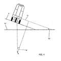
Fig. 4 is a symbolic vertical plane view of a vehicle on a laterally inclined plane with respect to the horizontal plane, and of the composition of the forces, in particular lateral ones, that act on said vehicle; -
Fig. 5 is a graph similar to the graph ofFig. 3 , but with a simplified mode of operation of the invention; -
Fig. 6 shows further graphs similar to the graph ofFig. 3 , but according to improved variants and modes of the invention; -
Figures 7A ,7B and7C illustrate respectively a perspective view and the two plane orthogonal views of an operating vehicle suitable for implementing the invention; -
Fig. 8A illustrates a perspective view of a second type of operating vehicle particularly suitable for being equipped with the invention: -
Figures 8B ,8C and 8D illustrate respectively orthogonal plane views of the vehicle ofFig. 8A . - As mentioned at the beginning, the present invention has the objective of improving the stability of an operating vehicle, in particular a floor-washing or a floor-brushing machine.
- This objective is achieved on the basis of the circumstance that the physical quantity most directly responsible for the loss of grip or stability (that determines the tipping over) of a vehicle of this type is the acceleration in a direction perpendicular to the instantaneous direction of movement of the vehicle. When this acceleration exceeds a certain limit, depending on the constructive characteristics of the vehicle and other contingent factors, such as the grip of the wheels on the ground, there is the loss of grip or the lateral tipping over of the vehicle, depending on the greater or lesser lateral grip coefficient of the wheels with respect to the quantity of centrifugal acceleration applied to the centre of gravity, and also to the distance of the same above ground level.
- With reference to
Fig. 1 , an operating vehicle according to a preferred embodiment of the invention employs the following means: - a
frame 1 suited to support at least preferably parallel two axles 2, 3 on each of which is mounted one or more wheels; - a rectilinear direction of travel "X", referring to said frame, and defined by the orientation of said wheels when they are oriented parallel to each other. Naturally, other configurations of the frame and the relative axles are possible; in any case, the vehicle must be able to proceed in a rectilinear direction of travel "X";
- an
accelerometer 4 oriented:- o at right angles with respect to said direction "X",
- o and in a horizontal direction when said wheels are resting on a horizontal working surface and the vehicle is stationary with respect to said working surface,
- a command and control unit 9 (hereinafter also called simply unit 9) suited to receive said electric signal generated by said accelerometer and to process said signal according to predefined algorithms;
- traction means 6 suited to operate in a controlled manner on one or preferably more driving wheels;
(In operating machines in which an elective embodiment of the invention is applied, said traction means are preferably one or more electric motors, or a hydraulic drive is employed interlocked with a suitable internal combustion engine, without thereby excluding the use of other types of traction means, and therefore also a conventional internal combustion engine that transfers the power delivered to the wheels through traction means that will be better explained hereinbelow.) - control means 7 operated by the machine operator and suitable to control the power delivered by said traction means 6; in general, in operating machines typically considered by the invention said control means include a single pedal, operated by the operator, that operates on said traction means.
- Heretofore, a general description of a vehicle according to the known technique has been described, wherein there is no functional connection between the control of said traction means, and therefore the power delivered by the same, and the signal generated and transmitted by said accelerometer.
- On the other hand, the present invention sets itself the objective of:
- setting, for the vehicle having the characteristics of the invention, the maximum value of lateral acceleration that it can tolerate in full safety (this maximum value can be found in a completely theoretical manner or, more simply and effectively, it can be determined and verified through specific experiments on a vehicle having the same characteristics as the one provided with the invention);
- establishing and controlling the speed of the same vehicle so that it is limited to the point at which said maximum value of lateral acceleration is never exceeded, and these control actions must be actuated completely automatically, that is without any action by the operator, and independently of the any manoeuvres by the operator typically on the steering wheel and on the traction means.
- For this purpose, a relationship is established and predetermined between the signal generated by the
accelerometer 4 and the power delivered by said traction means 6. - With reference to
Fig. 2 , acontrol unit 9 is realized designed to receive both the signal coming from theaccelerator 4, and the signal coming from asuitable transducer 8 that senses the instantaneous position of thepedal 7, or the pressure on the pedal, depending on the type of control. - Both these signals are computed and processed by said
unit 9 according to a predetermined algorithm that will be better described and specified hereinbelow; the result of the computation is transmitted to asuitable servo control 10 suitable to act directly on the traction means 6. - However, it should be immediately explained that said signals are not processed together, and specifically the signal originated by the accelerometer is measured in real time, and, on the basis (according to said algorithm) of the instantaneous value detected, a second signal is generated and sent to said
servo control 10 forming the control signal controlling the power that must be delivered by thetraction system 6 of the vehicle. - A purely constructive variant consists of integrating the
control unit 9 with saidservo control 10; in any case, independently of the type of construction, said twounits - In this manner, a solution is achieved in which the traction means is controlled on the basis of both the controlling action of the
pedal 7 and the centrifugal or lateral acceleration detected and transmitted by theaccelerometer 4. - For what concerns the type of algorithm, and therefore the command system of said
control unit 9, reference is made toFig. 3 . -
Fig. 3 shows a system of Cartesian coordinates in which the axis of abscissas represents the value of the lateral acceleration in absolute value (in this case expressed in hundredths of "g"), and in which the axis of ordinates represents the output function from saidcontrol unit 9 that controls the power delivered by the traction means 6, expressed as a limitation of the real speed of the vehicle with respect to the speed requested by the operator through the pressure on thepedal 7. - As can be seen, the graph shown therein consists of a broken line formed by three segments in succession; each of the three segments represents a mode of operation of the invention, as follows:
- Segment A): the operating speed is not modified; in fact, once a given value "A1" of lateral acceleration is preset, here exemplified by the value of 0.18 g, when in this segment the lateral acceleration is maintained below said value, said
control unit 9 supplies a signal that faithfully represents the position control of thepedal 7; - Segment B): the operating speed is modified in a linear manner with respect to the position of the
pedal 7; in fact, when in this segment the lateral acceleration is maintained between the previous value "A1 and a new and higher lateral acceleration value "B1", saidcontrol unit 9 supplies a signal suitable to limit proportionately the machine speed; - Segment C): the machine operating speed is subjected to the complete control of the
control unit 9; in fact, when in this segment the lateral acceleration is maintained higher than said value "B1", saidcontrol unit 9 supplies a signal suitable to maintain the speed of the vehicle at a predetermined constant value "V1 ". - It can now be seen, and immediately clear to an expert in the field, that the vehicle provided with the invention, in the absence of transients with high peaks of acceleration, will always tend to work in the limited zone that includes the intersection "I" between segment "A" and segment "B", and, if the signal on the
pedal 7 is permanently activated for the maximum speed, it will tend to remain in this intersection "I" until either the speed control signal is reduced or the centrifugal acceleration is reduced. - In fact, if the inventive device senses a centrifugal acceleration that corresponds to segment "B", it instantaneously reduces the speed of the vehicle, which automatically reduces the centrifugal force detected, and then the speed of the vehicle is increased again until a new correction is made.
- Essentially, the speed of the vehicle and its lateral acceleration are maintained in a stable equilibrium, meaning that they can be continually modified so that the point that represents them on the diagram of
Fig. 3 tends continually toward said position "I", oscillating around it. - The fundamental objective of the invention should be underlined: in fact, it tends to avoid bringing the vehicle up to the extreme condition before the point of tipping over, while yet preventing it, but to achieve a condition of travel that shows a high safety coefficient (Point "I") well before reaching the risk of tipping over.
- The advantages of the present invention, with respect to other non-automatic control systems, like the reduction of the speed connected to the steering angle of the vehicle, are thus the following:
- 1) absence of intervention of the inventive devices when the speed of the vehicle is sufficiently reduced so as not to create hazardous situations (that is, excessive lateral acceleration), independently of the turning radius activated;
- 2) intervention proportional to the effective extent of the risk, and real-time automatic control of the vehicle speed so as to always maintain the maximum speed allowed by the selected safety conditions, as a function of the centrifugal acceleration detected;
- 3) "safety" intervention even when the vehicle is moving on a laterally inclined plane; in fact, if the vehicle, even if moving at a constant speed in a straight line, travels on a plane laterally inclined by an angle "p" with respect to the horizontal plane "o", as shown schematically in
Fig. 4 , it is still subjected to a lateral force "F1" that corresponds to the projection of the force of gravity "g" on the working plane "p". - Said lateral force "F1" is the force perceived by the
accelerometer 4 in a condition of a vehicle travelling in a uniform rectilinear motion, and corresponds evidently to:
if "b" is the angle of inclination of the plane "p" with respect to the horizontal plane "o". - Said lateral force F1 is thus detected by the accelerometer, and is thus used by the inventive devices to slow down the motion of the vehicle, thereby contributing to increase its operating safety.
- 4) The existence of Segment "C" in
Fig. 3 also provides the following additional advantages:- in case of movement on a laterally inclined plane, it is essential that the speed be kept from slowing down below a limit necessary for the vehicle to disengage itself in particular conditions, such as for example a slippery or very wet surface;
- in addition, in case of peaks of acceleration caused also by sudden changes of direction, it is better that the speed be prevented from undergoing excessive "decelerations", as otherwise this could determine more risks than benefits for the stability of the vehicle, since in this case the acceleration in the direction of travel is summed up vectorially with the lateral acceleration.
- And moreover the comfort of the operator would be appreciably lowered.
- The invention, as exemplified in the graph of
Fig. 3 , can also be realized, in a more simplified embodiment, represented inFig. 5 , with similar devices which however include only the Segments "A" and "B", meaning that they do not include segment "C". - Naturally, in this case the benefits described above are lost, and however it cannot be ruled out that, at least conceivably, a basic operation of the invention represented by the two Segments "A" and "B" alone is still advantageous in certain circumstances.
- Thus the operation of the vehicle, represented by the graph of
Fig. 3 , should be considered an improved embodiment of the invention. - This also allows numerous other advantageous improvements:
- a) the line broken into segments shown in
Fig. 3 may be chosen because it is simpler to realize and because it is the one most comfortable for the operator; and moreover, also because the sudden, though modest, variation in the vehicle speed already serves to indicate to the operator that the inventive devices have intervened, and therefore immediately signals that the vehicle has travelled into a "controlled risk" area. - However, other forms of embodiment of the graph of intervention of the invention, singling out particular running conditions and then realizing the appropriate corresponding algorithms that represent that specific type of graph are possible. For example, with reference to
Fig. 6 , it is possible to identify a non-linear relation between centrifugal acceleration and speed as represented by the curve "C1 ". - In fact, in this case at point "I" the speed of the vehicle does not decrease linearly with the increasing speed of the vehicle, but said speed decreases initially more markedly, that is with a greater deceleration, and then proceeds with a more limited, and progressively more limited, deceleration (of speed, but not of angular deceleration).
- With such a relation, the vehicle is allowed to abruptly decrease its speed when it exceeds the maximum intervention speed, and it may be preferred, for example, when wishing to "warn" the operator, by means of this abrupt decrease in speed, detected by point "I", that the vehicle has entered a running condition controlled by the inventive devices, in other words that a condition has been reached which could precede the condition of danger.
- This first type of operation is represented in
Fig. 5 by the curve "C1 ", which has an upward-facing concavity, as can be easily seen. - On the other hand, the curve "C2" can be chosen when wishing to operate the vehicle at a higher speed, that is, when the vehicle is always working in optimal conditions, such as when, for example, the surface on which the vehicle works is completely flat and horizontal, and the condition of the ground can also allow a definite and limited "trespassing" toward a completely temporary condition of greater risk, but also of greater productivity of the vehicle.
- This second type of operation is represented in
Fig. 5 by the curve "C2", which presents a downward facing concavity, as can be easily seen. - Essentially, and in the widest general terms, the algorithm that defines the relation between the speed and angular acceleration of the vehicle may be chosen at will in accordance with all possible conditions of both the vehicle and the ground.
- This possibility of adjusting the speed control algorithm suggests moreover some other improvements:
- b) With reference to
Figures 7a to 7c , which illustrate the three projections of a floor treatment vehicle, and on which is optionally mounted the inventive device, it can be seen that said vehicle has a track width of about 2 metres, that is much greater than the track width of the rear wheels, which is 88 cm. - In addition, its centre of gravity is shifted considerably upward, in order to:
- limit the width of the vehicle within a minimum value;
- and because its load consists basically of water tanks that are filled and emptied during the operation of the same vehicle which are arranged in its load bin on the upper rear part of the vehicle.
- In fact, a floor-washing vehicle of this type is provided with two tanks: a first tank initially full of water which during its use is sprayed and spread on the floor, and that then is immediately sucked up again and fed into the second tank, which is normally located above the first tank.
- Basically, both due to its geometrical dimensions and the arrangement of the load, this vehicle is inherently very unstable, if compared with a normal commercial vehicle.
- In addition, since the load of the vehicle can, and in fact must vary during the operation, in other words as explained above the load of washing water is transferred, after one pass on the ground, from the lower tank to the upper tank, this can also cause an upward shift of the centre of gravity of the vehicle, with the result of further deteriorating the characteristics of stability.
- A similar circumstance occurs when the vehicle is a sweeping machine, that is a machine that collects the dirt from the ground and transfers it into a collecting bin mounted on the machine itself. Since the collected material often includes significant portions of soil or, worse, fine gravel, in other words high density materials, there is in this case too a significant upward shift of the centre of gravity, which deteriorates the stability of the vehicle.
- The danger of lateral tipping of the vehicle becomes even more acute when the vehicle used is of the type illustrated in
Figures 8A to 8D ; in this case, in fact, the intrinsic risk of reduced lateral stability of the vehicle is aggravated by the fact that the operator's position is even higher than the vehicle, as he sits on a seat above the vehicle. This circumstance contributes non only to worsening the lateral stability of the vehicle but also, in the event of the vehicle tipping over, the body of the operator, who is not protected by side guards, will be thrown directly on the ground. - To solve this problem, and referring again to
Fig. 3A , the present improvement consists of modifying correspondingly the control algorithm ofFigure 3 or5 , so as to restore the original characteristics of lateral stability, or to set new, preferred characteristics of stability. - In effect, the improvement proposed herein consists of providing devices suitable to modify the algorithm in a selectively controllable manner so that the graph that represents it, and that in
Fig. 3 is represented by the broken line that comprises the three segments A, B and C, can be translatable in a horizontal direction so that it can occupy a plurality of positions, such as for example the position described by the graph "H1" shifted completely to the right, or by the graph "H2" shifted completely to the left. - Based on the explanations given to this point, it is evident that the graph "H1" illustrates a control of the vehicle in which the lateral acceleration threshold (point "I-1"), in which an inventive device intervenes to limit the speed of the vehicle, is higher, and therefore it adapts better to the case of more stable vehicles, or to the case of a vehicle itself with better characteristics of stability, for example when its centre of gravity is lower.
- Using the example of the vehicle described above, in which the centre of gravity rises progressively during the washing/sweeping procedure, it is therefore appropriate to select at the start of the operations the algorithm to which said graph "H1" corresponds.
- Afterward, as work proceeds and thus with the progressive rise of the centre of gravity, to guarantee and maintain a suitable operating safety it is naturally necessary to reduce the speed, and said reduction can be achieved by varying the algorithm or by introducing, from a suitable memory, a series of algorithms in succession.
- At the completion of the work it will naturally be evident that, in the example provided, the algorithm corresponding to graph "H2" will be inserted, allowing the minimum lateral acceleration, at point "I-2" before limiting the speed, given that in these final conditions the centre of gravity of the vehicle is the highest possible and therefore the dynamic stability of the vehicle is at its worst.
- Naturally the devices, typically electronic, to introduce the algorithm change or substitution command in the
control unit 9, are easily realizable by an expert in the field, and therefore they are not discussed further. - c) The foregoing improvement allows a useful completion; in fact, in certain cases the vehicle to be controlled is a large vehicle that can carry out various types of work. For example, it may carry a large bin on its upper part, or it can be provided with blades in the lower part, or, as already seen, it may be fitted with one or more tanks with a variable load.
- It is evident that each of these types of loads causes an appreciable upward or downward shift of the centre of gravity of the vehicle, and it is therefore clear that its characteristics of lateral stability are thereby strongly modified.
- According to the present improvement, the vehicle is equipped with means of selection suitable to set a specific algorithm, from among a plurality of algorithms stored in said
control unit 9, so as to supply a signal to input in said servo-control unit 10 in order that: - a) a specific algorithm is associated to each type of load, and
- b) the vehicle is provided with means of selection that are simple, immediately recognizable and that can be operated by the operator of the vehicle, and suitable to select the respective algorithm for each type of load.
- In practice, and to provide a simple example of implementation, it is sufficient to have on the instrument panel a multiple-position selector, in which every position is associated with one type of load; each position on said selector controls the algorithm that is designed and selected specifically for the type of load indicated for that respective selector position.
- Naturally, many forms of implementation of this improvement are possible, but they are already known in the art.
- It will therefore be sufficient for the operator, for each type of work for which a specific equipment or load has been mounted on the vehicle, to actuate the control that selects that type of load or work. The inventive devices will automatically enter the algorithm that has been specifically designed for that type of work, and essentially the operator will no longer have to worry about the lateral stability of the vehicle, even if it has been significantly modified with respect to the previous trim relative to a corresponding work of different type.
- d) What is newly explained above paves the way for a further valuable improvement: in fact, if the load on the vehicle is considerable and if it is shifted upward, so that it significantly conditions the position of the centre of gravity, and especially if said load is variable, it is evidently necessary, in order to optimize the lateral stability of the vehicle at any instant of operation, that also its characteristics of stability be correspondingly aligned, so as to ensure the programmed conditions of safety.
- This situation occurs frequently when vehicles of the floor-washing type are used, in which the water load is progressively shifted from a lower position to a higher position, naturally after the water is spread on the ground and subsequently sucked up.
- Or when using a sweeper that simply sucks up and collects materials, including soil and gravel, from the ground and discharges them into a collecting bin located on the vehicle itself, normally in an elevated position.
- In these conditions, the stability of the vehicle is continually modified and, if the operating conditions are not adapted accordingly, the characteristics of safety are diminished.
- Thus, to adapt the running conditions to the variable load (centre of gravity), the present improvement teaches the generation of a function that represents, with the varying progression of a reference or control variable, the corresponding variation of an electric signal to send to a vehicle monitoring and
control unit 9 so that it selects the algorithm that is most appropriate, and predetermined in fact according to said control signal. - Simply speaking, it will be sufficient to determine the reference value that represents the load variation with the necessary fidelity and then to also calculate, based on that function, a signal that must be suitably reprocessed to redefine the running conditions of the vehicle.
- For example, in the variable that represents the load variation in the case illustrated above of two tanks that transfer (indirectly) the water load, the reference variable can be the quantity of water transferred, represented by a signal that integrates on a time base the instantaneous flow rate of pumped water. This reference signal can then be entered in an appropriate storage and calculation device suitable to generate a useful signal to modify in a predetermined and corresponding manner the shift, on the abscissa axis, of the graph that includes the three segments "A", "B" and "C" of
Figure 3 . - With another example, it is possible to see that said reference variable is simply time, and, assuming that the pumping flow rate is constant, the variation of the centre of gravity is immediately calculated, as is therefore also the continually variable characteristic of stability of the vehicle.
- Or, assuming that the load of material collected is also itself dependent on the operating time in a substantially linear manner, a similar logic can be applied, along with the relative operating modes and devices to achieve the present improvement.
- An expert observer cannot avoid noticing that said improvement realizes in practice an automation of the previous improvement described at point C); in fact, in this case too the position in the horizontal direction of the graph of
Fig. 3 is modified, but while in the previous case said modification/adjustment is carried out manually by the operator (who could also not remember such adjustment, or could carry it out in a wrong manner), with the present improvement such adjustment of the running of the vehicle based on its effective stability, carried out in continuous mode and in real time, in carried out in a completely automatic mode. - Schematically, this improvement is represented again in
Fig. 2 ; the figure shows a further processing andstorage unit 20 in which asignal 11 is received representative of the change of trim, that is the centre of gravity of the vehicle, and which processes and transmits anew signal 12 directed to saidcontrol unit 9. - Said
signal 11 is thus enabled to shift the position of the graph ofFig. 3 or of the corresponding graphs so as to maintain preset conditions of safety by automatically decreasing the vehicle speed when approaching situations of risk. - It is also worthwhile to note that in this latter case two independent forms of automatism are provided, which however are coordinated for the same purpose. Said forms of automatism are:
- the above-mentioned automatic speed adjustment as a function of angular acceleration, and
- the above-described selection of the algorithm governing the above-mentioned adjustment, as a function of variation of the load and thus of the vehicle centre of gravity.
Claims (7)
- Vehicle for the floor treatment, preferably a floor-washer or an industrial floor sweeper, comprising:- traction means (6), preferably made of an electric motor or of a thermal engine and coupled to an hydraulic transmission, able of controlling said wheels so as to cause them to rotate so driving said vehicle into motion,- a frame (1) supported by two axis (2, 3) on which one or more wheels are mounted, which are able of orienting the vehicle driving in a rectilinear direction (X),- an accelerometer (4) apt of detecting the side acceleration orthogonal to said rectilinear driving direction, and able of generating an electric signal depending on the acceleration imparted to said accelerometer,- command means (7) which can be acted by an operator and able of commanding in a controlled way the mechanical power of said traction means (6), so as to control the vehicle speed,- a command and control unit (9) able of receiving said electric signal and of processing it according to one or more pre-defined algorithms,
which are able of comparing the side acceleration signal detected by said accelerometer (4) with respect to a pre-determined level corresponding to a predetermined side acceleration (I), and processing means able of acting on said traction means (6), preferably through servo-controls (10), according to the result of said comparison between the signal of said side acceleration and to said pre-determined level,
characterized in that said command and control unit (9) is able of acting on said traction means (6) so as to keep the vehicle speed:- at a speed ("A") representing the condition of said command means (9) when the vehicle side acceleration is below a first pre-determined level ("A1),- at a speed ("B") linearly varying according to said vehicle side acceleration when said side acceleration ranges between said first predetermined level ("A1 ") and a second pre-determined level ("B1"),- at a pre-fixed speed (V1) when the signal of said accelerometer exceeds said second pre-determined level ("B1"). - . Vehicle according to claim 1, characterized in that the speed behavior, when over a pre-fixed level, with respect to the side acceleration, is represented by graph showing a concavity upwards (C1).
- . Vehicle according to claim 1, characterized in that the speed behavior, when over a pre-fixed level, with respect to the side acceleration, is represented by graph showing a concavity downwards (C2).
- . Vehicle according to any of the previous claims, characterized in that selections means are provided, which are able of modifying said pre-determined level, above which the vehicle speed is reduced in a controlled way, from a minimum level (I-2) to a selectively controllable higher level.
- . Vehicle according to claim 4, characterized in that said selection means are able of causing a specific profile of the speed behavior according to the side acceleration out of a plurality of selectable profiles, wherein each specific speed profile is associated to one specific vehicle trim or loading.
- . Vehicle according to any of the previous claims, characterized in that said selection means are able of defining a particular speed profile of the speed behavior according to the side acceleration among a plurality of selectable profiles, wherein each particular speed profile is chosen according to a signal (11) generated by said vehicle and which represents, according pre-programmed functions, the load situation or the barycenter of said vehicle, and the relevant modifications.
- . Vehicle according to claim 6, characterized in being provided with a processing and storing unit (20) able of receiving said signal (11) generated by said vehicle and representative of the changing of its loading or trim and able of transmitting a proper new signal to said command unit (9).
Applications Claiming Priority (2)
| Application Number | Priority Date | Filing Date | Title |
|---|---|---|---|
| ITPN2009A000067A IT1396698B1 (en) | 2009-11-11 | 2009-11-11 | PERFECT VEHICLE FOR THE TREATMENT AND CLEANING OF FLOORS AND SOILS |
| PCT/EP2010/064148 WO2011057854A1 (en) | 2009-11-11 | 2010-09-24 | Improved floor and pavement treatment and cleaning vehicle |
Publications (2)
| Publication Number | Publication Date |
|---|---|
| EP2499010A1 EP2499010A1 (en) | 2012-09-19 |
| EP2499010B1 true EP2499010B1 (en) | 2014-05-07 |
Family
ID=43016878
Family Applications (1)
| Application Number | Title | Priority Date | Filing Date |
|---|---|---|---|
| EP10757209.1A Active EP2499010B1 (en) | 2009-11-11 | 2010-09-24 | Improved floor and pavement treatment and cleaning vehicle |
Country Status (6)
| Country | Link |
|---|---|
| US (1) | US8490737B2 (en) |
| EP (1) | EP2499010B1 (en) |
| JP (1) | JP2013510754A (en) |
| CN (1) | CN102686422B (en) |
| IT (1) | IT1396698B1 (en) |
| WO (1) | WO2011057854A1 (en) |
Families Citing this family (4)
| Publication number | Priority date | Publication date | Assignee | Title |
|---|---|---|---|---|
| RU2585203C1 (en) * | 2014-12-31 | 2016-05-27 | Федеральное государственное бюджетное образовательное учреждение высшего профессионального образования "Оренбургский государственный аграрный университет" | Method of stabilising moving wheeled vehicle on inclined support surface |
| CN108664031B (en) * | 2018-05-31 | 2021-07-23 | 北京智行者科技有限公司 | Track processing method |
| AT17191U1 (en) * | 2020-04-01 | 2021-08-15 | Plasser & Theurer Export Von Bahnbaumaschinen Gmbh | System for editing a track |
| CN116263044B (en) * | 2021-12-13 | 2026-02-10 | 海沃机械(中国)有限公司 | Control methods and control systems for road cleaning vehicles |
Family Cites Families (19)
| Publication number | Priority date | Publication date | Assignee | Title |
|---|---|---|---|---|
| US2865462A (en) | 1956-03-01 | 1958-12-23 | Gen Motors Corp | Automotive vehicle having free control and stability features |
| US3717104A (en) | 1970-07-08 | 1973-02-20 | United Aircraft Corp | Active roll controling truck stabilizing mechanism |
| GB2257403A (en) * | 1991-07-06 | 1993-01-13 | Gloster Saro Ltd | Road vehicle stability indicating system. |
| JPH06297985A (en) * | 1993-04-19 | 1994-10-25 | Toyota Motor Corp | Controller for vehicle |
| JP3129259B2 (en) * | 1997-10-31 | 2001-01-29 | 株式会社豊田自動織機製作所 | Axle swing control method and axle swing control device for industrial vehicle |
| US6122568A (en) | 1998-12-22 | 2000-09-19 | Ford Global Technologies, Inc. | Method and apparatus for determining the dynamic stability of an automotive vehicle |
| JP3627575B2 (en) * | 1999-06-30 | 2005-03-09 | 日産自動車株式会社 | Vehicle tracking control device |
| JP3675240B2 (en) * | 1999-07-19 | 2005-07-27 | 日産自動車株式会社 | Vehicle tracking control device |
| JP3666342B2 (en) * | 2000-02-21 | 2005-06-29 | 日産自動車株式会社 | Travel control device |
| US6304809B1 (en) * | 2000-03-21 | 2001-10-16 | Ford Global Technologies, Inc. | Engine control monitor for vehicle equipped with engine and transmission |
| WO2002020318A1 (en) | 2000-09-09 | 2002-03-14 | Kelsey-Hayes Company | Lateral acceleration sensor compensation for an inclined measurement plane |
| US6829524B2 (en) | 2001-08-20 | 2004-12-07 | Wisys Technology Foundation, Inc. | Method and apparatus for estimating yaw rate in a wheeled vehicle and stability system |
| JP2005200212A (en) * | 2003-11-20 | 2005-07-28 | Mitsubishi Heavy Ind Ltd | Forklift fall prevention device |
| EP1655191B1 (en) * | 2004-11-04 | 2008-01-16 | Delphi Technologies, Inc. | Vehicle autonomous brake-apply system and method |
| SE528484C2 (en) | 2005-04-11 | 2006-11-28 | Advanced Inertial Measurement | Vehicle control system |
| JP4489675B2 (en) * | 2005-09-27 | 2010-06-23 | 本田技研工業株式会社 | snowblower |
| IL174061A0 (en) * | 2006-03-02 | 2006-08-01 | Amihud Rabin | Safety control system for electric vehicle |
| US8165771B2 (en) | 2006-08-31 | 2012-04-24 | Kabushikikaisha Equos Research | Vehicle |
| US8041492B2 (en) * | 2006-10-31 | 2011-10-18 | Clark Equipment Company | Engine load management for power machines |
-
2009
- 2009-11-11 IT ITPN2009A000067A patent/IT1396698B1/en active
-
2010
- 2010-09-24 JP JP2012538256A patent/JP2013510754A/en active Pending
- 2010-09-24 US US13/501,291 patent/US8490737B2/en active Active
- 2010-09-24 CN CN201080051300.2A patent/CN102686422B/en active Active
- 2010-09-24 WO PCT/EP2010/064148 patent/WO2011057854A1/en not_active Ceased
- 2010-09-24 EP EP10757209.1A patent/EP2499010B1/en active Active
Also Published As
| Publication number | Publication date |
|---|---|
| WO2011057854A1 (en) | 2011-05-19 |
| US8490737B2 (en) | 2013-07-23 |
| JP2013510754A (en) | 2013-03-28 |
| IT1396698B1 (en) | 2012-12-14 |
| ITPN20090067A1 (en) | 2011-05-12 |
| US20120199410A1 (en) | 2012-08-09 |
| CN102686422B (en) | 2016-01-20 |
| EP2499010A1 (en) | 2012-09-19 |
| CN102686422A (en) | 2012-09-19 |
Similar Documents
| Publication | Publication Date | Title |
|---|---|---|
| EP3807116B1 (en) | Grounds maintenance vehicle with traction and steering control system | |
| EP3060442B1 (en) | Vehicle speed control system | |
| US8527124B2 (en) | Traction control method and apparatus for a vehicle with independent drives | |
| US6435626B1 (en) | Steering and braking stability program | |
| JP6533231B2 (en) | Vehicle speed control system and vehicle speed control method | |
| EP2444304B1 (en) | System and method for preventing overturning of land vehicles | |
| EP3030445B1 (en) | Vehicle speed control system and method | |
| CN101878145A (en) | Method for operating a hydrostatically driven vehicle | |
| US8600621B2 (en) | System and method for controlling slip | |
| US8490737B2 (en) | Floor and pavement treatment and cleaning vehicle | |
| WO2013095918A1 (en) | Implement control system for a machine | |
| JP6879677B2 (en) | Work platform | |
| FI129756B (en) | Bogie balancing system and method for a work machine | |
| AU2012249535B2 (en) | Machine control system utilizing inertial yaw sensor | |
| KR0157276B1 (en) | Overturnning protection device for wheel type heavy machine | |
| JP4489675B2 (en) | snowblower | |
| JP7348868B2 (en) | Work vehicle transmission | |
| JPH0689536B2 (en) | Grader equipment | |
| CA3076716A1 (en) | Bogie balancing system and method for a work machine |
Legal Events
| Date | Code | Title | Description |
|---|---|---|---|
| PUAI | Public reference made under article 153(3) epc to a published international application that has entered the european phase |
Free format text: ORIGINAL CODE: 0009012 |
|
| 17P | Request for examination filed |
Effective date: 20120410 |
|
| AK | Designated contracting states |
Kind code of ref document: A1 Designated state(s): AL AT BE BG CH CY CZ DE DK EE ES FI FR GB GR HR HU IE IS IT LI LT LU LV MC MK MT NL NO PL PT RO SE SI SK SM TR |
|
| DAX | Request for extension of the european patent (deleted) | ||
| RAP1 | Party data changed (applicant data changed or rights of an application transferred) |
Owner name: NILFISK-ADVANCE A/S |
|
| 17Q | First examination report despatched |
Effective date: 20130906 |
|
| REG | Reference to a national code |
Ref country code: DE Ref legal event code: R079 Ref document number: 602010015913 Country of ref document: DE Free format text: PREVIOUS MAIN CLASS: B60G0017005000 Ipc: B60W0030040000 |
|
| RIC1 | Information provided on ipc code assigned before grant |
Ipc: B60W 30/04 20060101AFI20131202BHEP |
|
| GRAP | Despatch of communication of intention to grant a patent |
Free format text: ORIGINAL CODE: EPIDOSNIGR1 |
|
| INTG | Intention to grant announced |
Effective date: 20140204 |
|
| GRAS | Grant fee paid |
Free format text: ORIGINAL CODE: EPIDOSNIGR3 |
|
| GRAA | (expected) grant |
Free format text: ORIGINAL CODE: 0009210 |
|
| AK | Designated contracting states |
Kind code of ref document: B1 Designated state(s): AL AT BE BG CH CY CZ DE DK EE ES FI FR GB GR HR HU IE IS IT LI LT LU LV MC MK MT NL NO PL PT RO SE SI SK SM TR |
|
| REG | Reference to a national code |
Ref country code: GB Ref legal event code: FG4D |
|
| REG | Reference to a national code |
Ref country code: AT Ref legal event code: REF Ref document number: 666391 Country of ref document: AT Kind code of ref document: T Effective date: 20140515 |
|
| REG | Reference to a national code |
Ref country code: NL Ref legal event code: T3 |
|
| REG | Reference to a national code |
Ref country code: IE Ref legal event code: FG4D |
|
| REG | Reference to a national code |
Ref country code: DE Ref legal event code: R096 Ref document number: 602010015913 Country of ref document: DE Effective date: 20140618 |
|
| REG | Reference to a national code |
Ref country code: AT Ref legal event code: MK05 Ref document number: 666391 Country of ref document: AT Kind code of ref document: T Effective date: 20140507 |
|
| REG | Reference to a national code |
Ref country code: LT Ref legal event code: MG4D |
|
| PG25 | Lapsed in a contracting state [announced via postgrant information from national office to epo] |
Ref country code: GR Free format text: LAPSE BECAUSE OF FAILURE TO SUBMIT A TRANSLATION OF THE DESCRIPTION OR TO PAY THE FEE WITHIN THE PRESCRIBED TIME-LIMIT Effective date: 20140808 Ref country code: FI Free format text: LAPSE BECAUSE OF FAILURE TO SUBMIT A TRANSLATION OF THE DESCRIPTION OR TO PAY THE FEE WITHIN THE PRESCRIBED TIME-LIMIT Effective date: 20140507 Ref country code: NO Free format text: LAPSE BECAUSE OF FAILURE TO SUBMIT A TRANSLATION OF THE DESCRIPTION OR TO PAY THE FEE WITHIN THE PRESCRIBED TIME-LIMIT Effective date: 20140807 Ref country code: IS Free format text: LAPSE BECAUSE OF FAILURE TO SUBMIT A TRANSLATION OF THE DESCRIPTION OR TO PAY THE FEE WITHIN THE PRESCRIBED TIME-LIMIT Effective date: 20140907 Ref country code: LT Free format text: LAPSE BECAUSE OF FAILURE TO SUBMIT A TRANSLATION OF THE DESCRIPTION OR TO PAY THE FEE WITHIN THE PRESCRIBED TIME-LIMIT Effective date: 20140507 Ref country code: CY Free format text: LAPSE BECAUSE OF FAILURE TO SUBMIT A TRANSLATION OF THE DESCRIPTION OR TO PAY THE FEE WITHIN THE PRESCRIBED TIME-LIMIT Effective date: 20140507 |
|
| PG25 | Lapsed in a contracting state [announced via postgrant information from national office to epo] |
Ref country code: ES Free format text: LAPSE BECAUSE OF FAILURE TO SUBMIT A TRANSLATION OF THE DESCRIPTION OR TO PAY THE FEE WITHIN THE PRESCRIBED TIME-LIMIT Effective date: 20140507 Ref country code: AT Free format text: LAPSE BECAUSE OF FAILURE TO SUBMIT A TRANSLATION OF THE DESCRIPTION OR TO PAY THE FEE WITHIN THE PRESCRIBED TIME-LIMIT Effective date: 20140507 Ref country code: SE Free format text: LAPSE BECAUSE OF FAILURE TO SUBMIT A TRANSLATION OF THE DESCRIPTION OR TO PAY THE FEE WITHIN THE PRESCRIBED TIME-LIMIT Effective date: 20140507 Ref country code: HR Free format text: LAPSE BECAUSE OF FAILURE TO SUBMIT A TRANSLATION OF THE DESCRIPTION OR TO PAY THE FEE WITHIN THE PRESCRIBED TIME-LIMIT Effective date: 20140507 Ref country code: PL Free format text: LAPSE BECAUSE OF FAILURE TO SUBMIT A TRANSLATION OF THE DESCRIPTION OR TO PAY THE FEE WITHIN THE PRESCRIBED TIME-LIMIT Effective date: 20140507 Ref country code: LV Free format text: LAPSE BECAUSE OF FAILURE TO SUBMIT A TRANSLATION OF THE DESCRIPTION OR TO PAY THE FEE WITHIN THE PRESCRIBED TIME-LIMIT Effective date: 20140507 |
|
| PG25 | Lapsed in a contracting state [announced via postgrant information from national office to epo] |
Ref country code: PT Free format text: LAPSE BECAUSE OF FAILURE TO SUBMIT A TRANSLATION OF THE DESCRIPTION OR TO PAY THE FEE WITHIN THE PRESCRIBED TIME-LIMIT Effective date: 20140908 |
|
| PG25 | Lapsed in a contracting state [announced via postgrant information from national office to epo] |
Ref country code: RO Free format text: LAPSE BECAUSE OF FAILURE TO SUBMIT A TRANSLATION OF THE DESCRIPTION OR TO PAY THE FEE WITHIN THE PRESCRIBED TIME-LIMIT Effective date: 20140507 Ref country code: DK Free format text: LAPSE BECAUSE OF FAILURE TO SUBMIT A TRANSLATION OF THE DESCRIPTION OR TO PAY THE FEE WITHIN THE PRESCRIBED TIME-LIMIT Effective date: 20140507 Ref country code: BE Free format text: LAPSE BECAUSE OF FAILURE TO SUBMIT A TRANSLATION OF THE DESCRIPTION OR TO PAY THE FEE WITHIN THE PRESCRIBED TIME-LIMIT Effective date: 20140507 Ref country code: SK Free format text: LAPSE BECAUSE OF FAILURE TO SUBMIT A TRANSLATION OF THE DESCRIPTION OR TO PAY THE FEE WITHIN THE PRESCRIBED TIME-LIMIT Effective date: 20140507 Ref country code: CZ Free format text: LAPSE BECAUSE OF FAILURE TO SUBMIT A TRANSLATION OF THE DESCRIPTION OR TO PAY THE FEE WITHIN THE PRESCRIBED TIME-LIMIT Effective date: 20140507 Ref country code: EE Free format text: LAPSE BECAUSE OF FAILURE TO SUBMIT A TRANSLATION OF THE DESCRIPTION OR TO PAY THE FEE WITHIN THE PRESCRIBED TIME-LIMIT Effective date: 20140507 |
|
| REG | Reference to a national code |
Ref country code: DE Ref legal event code: R097 Ref document number: 602010015913 Country of ref document: DE |
|
| PLBE | No opposition filed within time limit |
Free format text: ORIGINAL CODE: 0009261 |
|
| STAA | Information on the status of an ep patent application or granted ep patent |
Free format text: STATUS: NO OPPOSITION FILED WITHIN TIME LIMIT |
|
| 26N | No opposition filed |
Effective date: 20150210 |
|
| PG25 | Lapsed in a contracting state [announced via postgrant information from national office to epo] |
Ref country code: LU Free format text: LAPSE BECAUSE OF FAILURE TO SUBMIT A TRANSLATION OF THE DESCRIPTION OR TO PAY THE FEE WITHIN THE PRESCRIBED TIME-LIMIT Effective date: 20140924 Ref country code: MC Free format text: LAPSE BECAUSE OF FAILURE TO SUBMIT A TRANSLATION OF THE DESCRIPTION OR TO PAY THE FEE WITHIN THE PRESCRIBED TIME-LIMIT Effective date: 20140507 |
|
| REG | Reference to a national code |
Ref country code: CH Ref legal event code: PL |
|
| REG | Reference to a national code |
Ref country code: DE Ref legal event code: R097 Ref document number: 602010015913 Country of ref document: DE Effective date: 20150210 |
|
| GBPC | Gb: european patent ceased through non-payment of renewal fee |
Effective date: 20140924 |
|
| REG | Reference to a national code |
Ref country code: IE Ref legal event code: MM4A |
|
| PG25 | Lapsed in a contracting state [announced via postgrant information from national office to epo] |
Ref country code: CH Free format text: LAPSE BECAUSE OF NON-PAYMENT OF DUE FEES Effective date: 20140930 Ref country code: SI Free format text: LAPSE BECAUSE OF FAILURE TO SUBMIT A TRANSLATION OF THE DESCRIPTION OR TO PAY THE FEE WITHIN THE PRESCRIBED TIME-LIMIT Effective date: 20140507 Ref country code: LI Free format text: LAPSE BECAUSE OF NON-PAYMENT OF DUE FEES Effective date: 20140930 Ref country code: GB Free format text: LAPSE BECAUSE OF NON-PAYMENT OF DUE FEES Effective date: 20140924 |
|
| PG25 | Lapsed in a contracting state [announced via postgrant information from national office to epo] |
Ref country code: IE Free format text: LAPSE BECAUSE OF NON-PAYMENT OF DUE FEES Effective date: 20140924 |
|
| PGFP | Annual fee paid to national office [announced via postgrant information from national office to epo] |
Ref country code: NL Payment date: 20150917 Year of fee payment: 6 |
|
| PG25 | Lapsed in a contracting state [announced via postgrant information from national office to epo] |
Ref country code: SM Free format text: LAPSE BECAUSE OF FAILURE TO SUBMIT A TRANSLATION OF THE DESCRIPTION OR TO PAY THE FEE WITHIN THE PRESCRIBED TIME-LIMIT Effective date: 20140507 |
|
| PG25 | Lapsed in a contracting state [announced via postgrant information from national office to epo] |
Ref country code: BG Free format text: LAPSE BECAUSE OF FAILURE TO SUBMIT A TRANSLATION OF THE DESCRIPTION OR TO PAY THE FEE WITHIN THE PRESCRIBED TIME-LIMIT Effective date: 20140507 Ref country code: MT Free format text: LAPSE BECAUSE OF FAILURE TO SUBMIT A TRANSLATION OF THE DESCRIPTION OR TO PAY THE FEE WITHIN THE PRESCRIBED TIME-LIMIT Effective date: 20140507 |
|
| PG25 | Lapsed in a contracting state [announced via postgrant information from national office to epo] |
Ref country code: TR Free format text: LAPSE BECAUSE OF FAILURE TO SUBMIT A TRANSLATION OF THE DESCRIPTION OR TO PAY THE FEE WITHIN THE PRESCRIBED TIME-LIMIT Effective date: 20140507 Ref country code: HU Free format text: LAPSE BECAUSE OF FAILURE TO SUBMIT A TRANSLATION OF THE DESCRIPTION OR TO PAY THE FEE WITHIN THE PRESCRIBED TIME-LIMIT; INVALID AB INITIO Effective date: 20100924 |
|
| REG | Reference to a national code |
Ref country code: FR Ref legal event code: PLFP Year of fee payment: 7 |
|
| REG | Reference to a national code |
Ref country code: NL Ref legal event code: MM Effective date: 20161001 |
|
| PG25 | Lapsed in a contracting state [announced via postgrant information from national office to epo] |
Ref country code: NL Free format text: LAPSE BECAUSE OF NON-PAYMENT OF DUE FEES Effective date: 20161001 |
|
| REG | Reference to a national code |
Ref country code: FR Ref legal event code: PLFP Year of fee payment: 8 |
|
| PG25 | Lapsed in a contracting state [announced via postgrant information from national office to epo] |
Ref country code: MK Free format text: LAPSE BECAUSE OF FAILURE TO SUBMIT A TRANSLATION OF THE DESCRIPTION OR TO PAY THE FEE WITHIN THE PRESCRIBED TIME-LIMIT Effective date: 20140507 |
|
| REG | Reference to a national code |
Ref country code: FR Ref legal event code: PLFP Year of fee payment: 9 |
|
| PG25 | Lapsed in a contracting state [announced via postgrant information from national office to epo] |
Ref country code: AL Free format text: LAPSE BECAUSE OF FAILURE TO SUBMIT A TRANSLATION OF THE DESCRIPTION OR TO PAY THE FEE WITHIN THE PRESCRIBED TIME-LIMIT Effective date: 20140507 |
|
| P01 | Opt-out of the competence of the unified patent court (upc) registered |
Effective date: 20230509 |
|
| REG | Reference to a national code |
Ref country code: DE Ref legal event code: R081 Ref document number: 602010015913 Country of ref document: DE Owner name: NILFISK A/S, DK Free format text: FORMER OWNER: NILFISK-ADVANCE A/S, BRONDBY, DK |
|
| PGFP | Annual fee paid to national office [announced via postgrant information from national office to epo] |
Ref country code: DE Payment date: 20250820 Year of fee payment: 16 |
|
| PGFP | Annual fee paid to national office [announced via postgrant information from national office to epo] |
Ref country code: IT Payment date: 20250820 Year of fee payment: 16 |
|
| PGFP | Annual fee paid to national office [announced via postgrant information from national office to epo] |
Ref country code: FR Payment date: 20250820 Year of fee payment: 16 |