EP2498554A1 - Power control method, base station and terminal for physical uplink control channel - Google Patents
Power control method, base station and terminal for physical uplink control channel Download PDFInfo
- Publication number
- EP2498554A1 EP2498554A1 EP10840400A EP10840400A EP2498554A1 EP 2498554 A1 EP2498554 A1 EP 2498554A1 EP 10840400 A EP10840400 A EP 10840400A EP 10840400 A EP10840400 A EP 10840400A EP 2498554 A1 EP2498554 A1 EP 2498554A1
- Authority
- EP
- European Patent Office
- Prior art keywords
- pucch
- power control
- transmitted power
- user equipment
- control information
- Prior art date
- Legal status (The legal status is an assumption and is not a legal conclusion. Google has not performed a legal analysis and makes no representation as to the accuracy of the status listed.)
- Granted
Links
Images


Classifications
-
- H—ELECTRICITY
- H04—ELECTRIC COMMUNICATION TECHNIQUE
- H04W—WIRELESS COMMUNICATION NETWORKS
- H04W52/00—Power management, e.g. Transmission Power Control [TPC] or power classes
- H04W52/04—Transmission power control [TPC]
- H04W52/30—Transmission power control [TPC] using constraints in the total amount of available transmission power
- H04W52/32—TPC of broadcast or control channels
- H04W52/325—Power control of control or pilot channels
-
- H—ELECTRICITY
- H04—ELECTRIC COMMUNICATION TECHNIQUE
- H04W—WIRELESS COMMUNICATION NETWORKS
- H04W52/00—Power management, e.g. Transmission Power Control [TPC] or power classes
- H04W52/04—Transmission power control [TPC]
- H04W52/30—Transmission power control [TPC] using constraints in the total amount of available transmission power
- H04W52/34—TPC management, i.e. sharing limited amount of power among users or channels or data types, e.g. cell loading
-
- H—ELECTRICITY
- H04—ELECTRIC COMMUNICATION TECHNIQUE
- H04W—WIRELESS COMMUNICATION NETWORKS
- H04W52/00—Power management, e.g. Transmission Power Control [TPC] or power classes
- H04W52/04—Transmission power control [TPC]
- H04W52/06—TPC algorithms
- H04W52/14—Separate analysis of uplink or downlink
- H04W52/146—Uplink power control
-
- H—ELECTRICITY
- H04—ELECTRIC COMMUNICATION TECHNIQUE
- H04W—WIRELESS COMMUNICATION NETWORKS
- H04W52/00—Power management, e.g. Transmission Power Control [TPC] or power classes
- H04W52/04—Transmission power control [TPC]
- H04W52/38—TPC being performed in particular situations
- H04W52/42—TPC being performed in particular situations in systems with time, space, frequency or polarisation diversity
-
- H—ELECTRICITY
- H04—ELECTRIC COMMUNICATION TECHNIQUE
- H04W—WIRELESS COMMUNICATION NETWORKS
- H04W52/00—Power management, e.g. Transmission Power Control [TPC] or power classes
- H04W52/04—Transmission power control [TPC]
- H04W52/54—Signalisation aspects of the TPC commands, e.g. frame structure
Definitions
- the present invention relates to the field of mobile communication, and more especially, to a power control method, a base station and a user equipment for a physical uplink control channel.
- uplink power control (called as power control for short) is used to control transmitted power of an uplink physical channel, to compensate path loss and shadow of the channel and suppress interference between cells.
- the uplink physical channel controlled by the uplink power control includes Physical Uplink Shared Channel (PUSCH), Physical Uplink Control Channel (PUCCH) and Sounding Reference Signal (SRS).
- PUSCH Physical Uplink Shared Channel
- PUCCH Physical Uplink Control Channel
- SRS Sounding Reference Signal
- the LTE uplink power control uses a control mode of combining an open loop with a closed loop.
- P CMAX is the Configured Maximum UE output power configured by the UE, and the value range of P CMAX is co-determined by multiple parameters, which include: the maximum UE power determined by the UE power class, the maximum configuration power of the system configuration (IE P-Max), the maximum configuration output power offset (P CMAX tolerance), Maximum Power Reduction (MPR) and Additional Maximum Power Reduction (A-MPR) and so on;
- P O_PUCCH is an open loop power control parameter, and is a sum of a cell-specific quantity P O_NOMINAL_PUCCH and a UE-specific quantity P O_UE PUCCH ;
- ⁇ F_PUCCH ( F ) is a power offset related to a PUCCH format(F) and configured by the upper level;
- h ( n ) is a value based on the PUCCH format(F), wherein, n CQI is the number of information bits of Channel Quality Indicator (CQI), and n HARQ is the number of bits of Hybri
- a power control adjustment state g ( i ) of the PUCCH on the subframe i is an accumulated value of a power control adjustment state g ( i -1) on the subframe i -1 and a Transmitted power Control (TPC) command ⁇ PUCCH indicated by the base station on the subframe i -4.
- TPC Transmitted power Control
- values of M and k m are related to Uplink and downlink configurations. That is, in the TDD system, the power control adjustment state g ( i ) of the PUCCH on the subframe i (i.e. the current power control adjustment state) is an accumulated value of the power control adjustment state g ( i -1) on the subframe i -1 and a sum of multiple transmitted power control commands ⁇ PUCCH indicated by the base station on subframes i-k 0 , i - k 1 , ⁇ , i - k M -1 .
- TDD Time Division Duplex
- the transmitted power control command ⁇ PUCCH is a UE-specific closed loop correction value and sent by the base station to a destination UE through a Physical Downlink Control Channel (PDCCH).
- PDCH Physical Downlink Control Channel
- the physical downlink control channel bears Downlink Control Information (DCI), which includes downlink or uplink scheduling information and an uplink transmitted power control command and so on.
- DCI Downlink Control Information
- the LTE system defines various downlink control information formats (DCI formats).
- the transmitted power control commands of the PUCCH are contained in DCI format 1A/1B/1D/1/2A/2 and DCI format 3/3A, each TPC command is of 1 bit or 2 bits and indicates a value of ⁇ PUCCH and a mapping relationship between the TPC command and ⁇ PUCCH is shown in tables 1 and 2.
- Table 1 the mapping relationship between the TPC Command and ⁇ PUCCH in DCI format 1A/1B/1D/1/2A/2/3 TPC Command Field inDCI format 1A/1B/1D/1/2A/2/3 ⁇ PUCCH [dB] 0 -1 1 0 2 1 3 3
- Table 2 the mapping relationship between the TPC command and in DCI format 3A TPC Command Field inDCI format 3A ⁇ PUCCH [dB] 0 -1 1 1
- DCI format 3/3A contain the TPC commands of multiple UEs, formats of DCI format 3/3A are as shown in table 1, and after receiving the DCI format 3/3A of the PDCCH, different UEs find out their own TPC commands in corresponding positions therein according to a parameter, namely "a transmitted power control index tpc-Index ", configured by the upper level.
- a transmitted power control index tpc-Index For the DCI format 3, the values of the transmitted power control index tpc-Index are the integers within the range of [1,15]; and for the DCI format 3A, the values of the transmitted power control indexes tpc-Index are the integers within the range of [1,31].
- DCI formats 1A/1B/1D/1/2A/2 only contain one TPC command aiming at the destination UE thereof.
- the TPC command is precisely the transmitted power control command of the PUCCH corresponding to a Physical Downlink Shared Channel (PDSCH) scheduled by the DCI format.
- PDSCH Physical Downlink Shared Channel
- ⁇ PUCCH 0 dB.
- the Physical Uplink Control Channel bears Uplink Control Information (UCI), which includes Scheduling Request (SR), response information (ACK/NACK) of the Physical Downlink Shared Channel (PDSCH), and feedback quantity/Precoding Matrix Indicator (PMI)/Rank Indication (RI) related to the CQI.
- UCI Uplink Control Information
- SR Scheduling Request
- ACK/NACK response information
- PMI Matrix Indicator
- RI Rank Indication
- a resource index of the PUCCH for sending the response information ACK/NACK of one or more PDSCHs is mapped implicitly by a Control Channel Element (CCE) index of the PDCCH which schedules the PDSCH, or is configured by an upper level signaling.
- CCE Control Channel Element
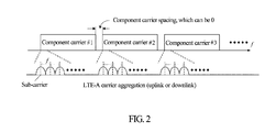
- LTE-A system In a LTE-Advanced system (called LTE-A system for short) is the next generation advanced system of the LTE system. As shown in FIG. 2 , the LTE-A system adopts a carrier aggregation technique to expand transmission bandwidth, and each aggregated carrier is called as one component carrier (CC). Multiple component carriers can be either successive or not successive, and can be located at either the same operating band or different operating bands.
- CC component carrier
- the user equipment can send multiple Physical Downlink Shared Channels (PDSCH) simultaneously on multiple (downlink) component carriers.
- the response information ACK/NACK of multiple PDSCHs can be sent by multiple Physical Uplink Control Channels (PUCCH) on one user equipment-specific (uplink) component carrier, or sent by one PUCCH on one user equipment-specific (uplink) component carrier.
- PUCCH Physical Uplink Control Channels
- the response information namely Acknowledge/Non-acknowledge (ACK/NACK)
- ACK/NACK Acknowledge/Non-acknowledge
- the user equipment determines the current power control adjustment state of the PUCCH and then determines the transmitted power of the PUCCH according to the transmitted power control commands indicated by the base station becomes a problem required to be solved urgently.
- the technical problem required to be solved by the present invention is to provide a power control method, a base station and a user equipment for a Physical Uplink Control Channel (PUCCH), wherein, when response information ACK/NACK of multiple Physical Downlink Shared Channels (PDSCH) sent by a base station on multiple component carriers is sent on one PUCCH, a user equipment can determine a current power control adjustment state of the PUCCH and then determine transmitted power of the PUCCH according to transmitted power control commands indicated by the base station.
- PUCCH Physical Uplink Control Channel
- the present invention provides a power control method for a Physical Uplink Control Channel, which comprises:
- the transmitted power control command is transmitted in downlink control information borne by a Physical Downlink Control Channel (PDCCH); wherein,
- the downlink control information is a downlink control information format encoded jointly by multiple transmitted power control commands; or the downlink control information is the downlink control information format(s) used to schedule one or more PDSCHs in the multiple PDSCHs.
- the method further comprises: the base station configuring a transmitted power control index for the PUCCH, which is used to indicate a position of the transmitted power control command in the downlink control information format encoded jointly by multiple transmitted power control commands.
- the method further comprises: sending the physical downlink control channel bearing the downlink control information format encoded jointly by multiple transmitted power control commands on a user equipment-specific component carrier; wherein, the specific component carrier comprises: a component carrier sending the physical uplink control channel, or a downlink component carrier paired with an uplink component carrier sending the physical uplink control channel, or an anchor component carrier of the user equipment.
- the base station sends a power control adjustment state g ( i ) of the PUCCH on a subframe i ;
- the power control adjustment state g ( i ) is an absolute value transmitted power control:
- g ( i -1) is the power control adjustment state of the PUCCH on a subframe i -1
- M and k m are related to configurations of a system
- ⁇ m 0 M - 1 ⁇ PUCCH ⁇ i - k m is a sum of the transmitted power control commands indicated by the base station on subframes i-k 0 , i -
- values of M and k m are related to uplink and downlink configurations of the time division duplex system.
- the method further comprises:
- ⁇ PUCCH ⁇ i - 4 func ⁇ PUCCH c 1 ⁇ i - 4 , ⁇ , ⁇ PUCCH c j ⁇ i - 4 , ⁇ , ⁇ PUCCH c N ⁇ i - 4
- ⁇ PUCCH ⁇ i - 4 ⁇ PUCCH c h ⁇ i - 4
- func ⁇ represents one function
- N is the number of PDSCHs transmitting response information thereof on the PUCCH
- ⁇ PUCCH c j ⁇ i - 4 is as follows: if the user equipment detects the downlink control information format used to schedule the physical downlink shared channel on the component carrier c j on a subframe i -4, the user equipment taking the transmitted power control commands contained in the downlink control information format as the ⁇ PUCCH c j ⁇ i - 4 , wherein, the component carrier c j is one of the multiple component carriers; if the user equipment detects the
- func ⁇ represents one function
- ⁇ PUCCH c j ⁇ i - k m is as follows:
- the method further comprises:
- the present invention further provides a base station, which is configured to:
- the base station is further configured to:
- the present invention further provides a user equipment, which is configured to:
- the user equipment is further configured to: when one or more downlink control information formats used to schedule multiple physical downlink shared channels on the multiple component carriers on the subframe i are detected, take the transmitted power control commands contained in the one or more downlink control information formats as the transmitted power control command ⁇ PUCCH ( i ) of the physical uplink control channel indicated by the base station on the subframe i ; if a downlink control information format encoded jointly by multiple transmitted power control commands on the subframe i is detected, take corresponding transmitted power control commands contained in the downlink control information format encoded jointly by the multiple transmitted power control commands as the transmitted power control command ⁇ PUCCH ( i ) of the physical uplink control channel indicated by the base station on the subframe i ; and if a user equipment does not detect one or more downlink control information formats used to schedule multiple physical downlink shared channels on the multiple component carriers on the subframe i , and if the user equipment does not detect the downlink control information format encoded jointly by the multiple transmitted power control commands on the subframe i ,
- ⁇ PUCCH ⁇ i - 4 ⁇ PUCCH c h ⁇ i - 4
- func ⁇ represents one function
- N is the number of PDSCHs transmitting the response information thereof on the PUCCH
- ⁇ PUCCH c j ⁇ i - 4 is as follows:
- func ⁇ represents one function
- ⁇ PUCCH c j ⁇ i - k m is as follows:
- the user equipment is further configured to: determine to use the accumulated value power control or absolute value power control for the PUCCH according to an upper level signaling.
- the power control method, base station and user equipment for the physical uplink control channel provided by the present invention solve the problem that, in the LTE-A system using the carrier aggregation, when the response information ACK/NACK of the Physical Downlink Shared Channels (PDSCH) on multiple component carriers is sent on one Physical Uplink Control Channel (PUCCH), how the user equipment determines a current power control adjustment state of the PUCCH and then determines transmitted power of the PUCCH according to the transmitted power control commands indicated by the base station.
- PDSCH Physical Downlink Shared Channels
- PUCCH Physical Uplink Control Channel
- step 301 when response information of multiple physical downlink shared channels sent by a base station over multiple component carriers is sent on one physical uplink control channel, the base station indicates a unified transmitted power control command for the physical uplink control channel.
- the transmitted power control command is transmitted in downlink control information borne by a physical downlink control channel, including but not limited to being transmitted in Downlink Control Information (DCI) format 3/3A encoded jointly by multiple transmitted power control commands, and is transmitted in downlink control information format(s) used to schedule one or more PDSCHs in the multiple PDSCHs, including but not limited to DCI format 1A/1B/1D/1/2A/2.
- DCI Downlink Control Information
- the base station configures a transmitted power control index tpc - index for the Physical Uplink Control Channel (PUCCH) of a user equipment, which is used to indicate the position of the transmitted power control command in the DCI format 3/3A encoded jointly by multiple transmitted power control commands.
- PUCCH Physical Uplink Control Channel
- the Physical Downlink Control Channel (PDCCH) bearing the DCI format 3/3A is sent on a user equipment-specific component carrier, including but not limited to being sent over a component carrier sending the physical uplink control channel (i.e. a time division duplex system), or being sent over a downlink component carrier paired with an uplink component carrier sending the physical uplink control channel (i.e. a frequency division duplex system), or being sent over an anchor Component Carrier of the user equipment.
- a component carrier sending the physical uplink control channel i.e. a time division duplex system
- an uplink component carrier sending the physical uplink control channel i.e. a frequency division duplex system
- an anchor Component Carrier of the user equipment i.e. a frequency division duplex system
- the user equipment detects one or more downlink control information formats used to schedule multiple physical downlink shared channels on the multiple component carriers on a subframe i , the user equipment takes the transmitted power control commands contained in the one or more downlink control information formats as the transmitted power control command ⁇ PUCCH ( i ) of the physical uplink control channel indicated by the base station on the subframe i ; otherwise, if the user equipment detects the downlink control information format encoded jointly by multiple transmitted power control commands on the subframe i , the user equipment takes corresponding transmitted power control commands contained in the downlink control information format encoded jointly by the multiple transmitted power control commands as the transmitted power control command ⁇ PUCCH ( i ) of the physical uplink control channel indicated by the base station on the subframe i ; and if the user equipment does not detect one or more downlink control information formats used to schedule multiple physical downlink shared channels on the multiple component carriers on the subframe i , or does not detect the downlink control information format encoded jointly by the multiple transmitted power control commands, then ⁇ PUCCH
- step 401 when ACK/NACK of multiple PDSCHs sent by a base station over multiple component carriers is sent on one PUCCH, the base station indicates multiple transmitted power control commands for the physical uplink control channel.
- the transmitted power control commands are transmitted in downlink control information borne by a physical downlink control channel, including but not limited to being transmitted in Downlink Control Information (DCI) format 3/3A encoded jointly by multiple transmitted power control commands, and are transmitted in downlink control information formats used to schedule multiple PDSCHs on the multiple component carriers, including but not limited to DCI format 1A/1B/1D/1/2A/2.
- DCI Downlink Control Information
- a user equipment detects a downlink control information format used to schedule a physical downlink shared channel on a component carrier c j on a subframe i , the user equipment takes the transmitted power control commands contained in the downlink control information format as the ⁇ PUCCH c j i , wherein, the component carrier c j is one of the multiple component carriers, and c j is a sequence number of the component carrier; otherwise, if the user equipment detects the downlink control information format encoded jointly by multiple transmitted power control commands on the subframe i , the user equipment takes the transmitted power control commands of the physical uplink control channel which bears the response information ACK/NACK of the physical downlink shared channel on the component carrier c j contained in the downlink control information format as the ⁇ PUCCH c j i ; and if the user equipment does not detect the downlink control information formats used to schedule multiple physical downlink shared channels on the component carrier on the subframe i , or does not detect the downlink control information format encoded jointly by the
- the N ⁇ PUCCH c j ⁇ i - k m s on a subframe i - k m also can be obtained according to the above description.
- a power control adjustment state i.e. a current power control adjustment state
- values of M and k m are related to uplink and downlink configurations of the system.
- formula (1) is called as an absolute value power control, that is:
- Formula (2) is called as an accumulated value power control, that is:
- the user equipment determines to use the accumulated value power control or absolute value power control for the physical uplink control channel according to a user equipment-specific accumulation-enabled power control parameter configured by an upper level signaling.
- the LTE-A system has five downlink component carriers D1, D2, D3, D4 and D5, and five uplink component carriers U1 U2, U3, U4 and U5.
- a base station sends physical downlink shared channels to a user equipment UE1 on the four downlink component carriers D1, D2, D3 and D4, and the user equipment UE1 will send response information ACK/NACK of four PDSCHs on the uplink component carrier U1 through one physical uplink control channel.
- the base station indicates a unified transmitted power control command for the physical uplink control channel.
- the base station sends the transmitted power control command used for the Physical Uplink Control Channel (PUCCH) of the user equipment UE1 in a Downlink Control Information (DCI) format 3 encoded jointly by multiple transmitted power control commands.
- PUCCH Physical Uplink Control Channel
- DCI Downlink Control Information
- a Physical Downlink Control Channel (PDCCH) bearing the DCI format 3 is sent over one user equipment-specific component carrier, for example, is sent over the downlink component carrier D1 paired with the uplink component carrier U1 which sends the Physical Uplink Control Channel (PUCCH), or is sent over an anchor component carrier D2 of the user equipment UE1.
- PUCCH Physical Downlink Control Channel
- the base station configures a transmitted power control index tpc-index for the Physical Uplink Control Channel (PUCCH) of the user equipment UE1, which is used to indicate the position of the transmitted power control command in the DCI format 3.
- PUCCH Physical Uplink Control Channel
- the user equipment UE1 determines to use accumulated value power control for the physical uplink control channel according to an accumulation-enabled power control parameter configured by an upper level signaling.
- PUCCH Physical Uplink Control Channel
- the LTE-A system has five downlink component carriers D1, D2, D3, D4 and D5, and five uplink component carriers U1, U2, U3, U4 and U5.
- a base station sends four physical downlink shared channels PDSCH1, PDSCH2, PDSCH3 and PDSCH4 to a user equipment UE1 on the four downlink component carriers D1, D2, D3 and D4 respectively, and the user equipment UE1 will send response information ACK/NACK of the four PDSCHs on the uplink component carrier U1 through one Physical Uplink Control Channel (PUCCH).
- the base station indicates a unified transmitted power control command for the PUCCH.
- the base station transmits the transmitted power control command used for the Physical Uplink Control Channel (PUCCH) in a downlink control information format which is sent to the user equipment UE1 and used to schedule the physical downlink shared channel PDSCH1 (or PDSCH2 or PDSCH3 or PDSCH4).
- PUCCH Physical Uplink Control Channel
- the base station transmits four identical transmitted power control commands used for the Physical Uplink Control Channel (PUCCH) in four downlink control information formats respectively which are sent to the user equipment UE1 and used to schedule the physical downlink shared channels PDSCH1, PDSCH2, PDSCH3 and PDSCH4.
- PUCCH Physical Uplink Control Channel
- the user equipment UE1 determines to use the absolute value power control for the physical uplink control channel according to an accumulation-enabled power control parameter configured by an upper level signaling.
- PUCCH Physical Uplink Control Channel
- LTE-A system works in a time division duplex mode, and the LTE-A system has five component carriers C1, C2, C3, C4 and C5.
- a base station sends physical downlink shared channels PDSCH1 and PDSCH2 to a user equipment UE1 over two downlink component carriers C1 and C2, and the user equipment UE1 will send response information ACK/NACK of the PDSCH1 and PDSCH2 on the uplink component carrier U1 through one Physical Uplink Control Channel (PUCCH).
- the base station indicates a unified transmitted power control command for the PUCCH.
- the base station transmits two identical transmitted power control commands used for the Physical Uplink Control Channel (PUCCH) in two downlink control information formats respectively which are sent to the user equipment UE1 and used to schedule the physical downlink shared channels PDSCH 1 and PDSCH 2.
- PUCCH Physical Uplink Control Channel
- the base station transmits one transmitted power control command used for the Physical Uplink Control Channel (PUCCH) in a downlink control information format which is sent to the user equipment UE1 and used to schedule the physical downlink shared channel PDSCH1 or PDSCH2, and sends an identical transmitted power control command used for the PUCCH in Downlink Control Information (DCT) format 3/3A encoded jointly by multiple transmitted power control commands.
- PUCCH Physical Uplink Control Channel
- DCT Downlink Control Information
- the user equipment UE1 determines to use the absolute value power control for the physical uplink control channel according to an Accumulation-enabled power control parameter configured by an upper level signaling.
- PUCCH Physical Uplink Control Channel
- the LTE-A system has five downlink component carriers D1, D2, D3, D4 and D5, and five uplink component carriers U1, U2, U3, U4 and U5.
- a base station sends four physical downlink shared channels PDSCH1, PDSCH2, PDSCH3 and PDSCH4 to a user equipment UE1 over the four downlink component carriers D1, D2, D3 and D4 respectively, and the user equipment UE1 will send response information ACK/NACK of the four PDSCHs over the uplink component carrier U1 through one Physical Uplink Control Channel (PUCCH).
- the base station indicates multiple transmitted power control commands for the PUCCH.
- the base station transmits four transmitted power control commands, which are respectively ⁇ PUCCH 1 i , ⁇ PUCCH 2 i , ⁇ PUCCH 3 i , ⁇ PUCCH 4 i and used for the Physical Uplink Control Channel (PUCCH), in four downlink control information formats respectively which are sent to the user equipment UE1 and used to schedule the physical downlink shared channels PDSCH1, PDSCH2, PDSCH3 and PDSCH4.
- PUCCH 1 i ⁇ PUCCH 1 i
- ⁇ PUCCH 2 i ⁇ PUCCH 2 i
- ⁇ PUCCH 3 i ⁇ PUCCH 4 i
- PUCCH 4 i Physical Uplink Control Channel
- the user equipment UE1 determines to use the absolute value power control for the physical uplink control channel according to an accumulation-enabled power control parameter configured by an upper level signaling.
- PUCCH Physical Uplink Control Channel
- LTE-A system works in a time division duplex mode, and the LTE-A system has five component carriers C1, C2, C3, C4 and C5.
- a base station sends physical downlink shared channels PDSCH1, PDSCH2, PDSCH3, PDSCH4 and PDSCH5 to a user equipment UE1 over five downlink component carriers C1, C2, C3, C4 and C5, and the user equipment UE1 will send response information ACK/NACK of the PDSCH1, PDSCH2, PDSCH3, PDSCH4 and PDSCH5 over the uplink component carrier U1 through two physical uplink control channels PDCCH1 and PDCCH2 respectively.
- the base station indicates multiple transmitted power control commands for the physical uplink control channels PDCCH1 and PDCCH2.
- the base station transmits three transmitted power control commands of ⁇ PUCCH 1 i , ⁇ PUCCH 2 i , ⁇ PUCCH 3 i used for the physical uplink control channel in three downlink control information formats which are sent to the user equipment UE1 and used to schedule the physical downlink shared channels PDSCH1, PDSCH2 and PDSCH3; and the base station transmits two transmitted power control commands of ⁇ PUCCH 4 i , ⁇ PUCCH 5 i used for the physical uplink control channel in two downlink control information formats which are sent to the user equipment UE1 and used to schedule the physical downlink shared channels PDSCH4 and PDSCH5.
- the user equipment UE1 determines to use the accumulated value power control for the physical uplink control channel according to an Accumulation-enabled power control parameter configured by an upper level signaling.
- g 1 ( i -1) and g 2 ( i -1) are power control adjustment states of the PUCCH1 and PUCCH2 respectively on a subframe i -1
- ⁇ PUCCH ( i - k m ) and ⁇ PUCCH ( i-k m ) are transmitted power control commands of the physical uplink control channels PUCCH1 and PUCCH2 respectively on a subframe i - k m .
- LTE-A system works in a time division duplex mode, and the LTE-A system has five component carriers C1, C2, C3, C4 and C5.
- a base station sends physical downlink shared channels PDSCH1, PDSCH2, PDSCH3, PDSCH4 and PDSCH5 to a user equipment UE1 over five downlink component carriers C1, C2, C3, C4 and C5, and the user equipment UE1 will send response information ACK/NACK of the PDSCH1, PDSCH2, PDSCH3, PDSCH4 and PDSCH5 over the U1 through two physical uplink control channels PDCCH1 and PDCCH2 respectively.
- the base station indicates multiple transmitted power control commands for the physical uplink control channels PDCCH1 and PDCCH2.
- the base station transmits four transmitted power control commands of ⁇ PUCCH 1 i , ⁇ PUCCH 2 i , ⁇ PUCCH 3 i , ⁇ PUCCH 4 i used for the physical uplink control channel in four downlink control information formats which are sent to the user equipment UE1 and used to schedule the physical downlink shared channels PDSCH1, PDSCH2, PDSCH3 and PDSCH4; and the base station sends one transmitted power control command ⁇ PUCCH 5 i used for the physical uplink control channel in Downlink Control Information (DCT) format 3/3A encoded jointly by multiple transmitted power control commands.
- DCT Downlink Control Information
- the user equipment UE1 determines to use the absolute value power control for the physical uplink control channel according to an accumulation-enabled power control parameter configured by an upper level signaling.
- the present invention in the LTE-A system adopting the carrier aggregation, when response information ACK/NACK of Physical Downlink Shared Channels (PDSCH) on multiple component carriers is sent on one Physical Uplink Control Channel (PUCCH), the problem that how a user equipment determines a current power control adjustment state of the PUCCH and then determines transmitted power of the PUCCH according to the transmitted power control commands indicated by the base station is solved.
- PDSCH Physical Downlink Shared Channels
- PUCCH Physical Uplink Control Channel
Landscapes
- Engineering & Computer Science (AREA)
- Computer Networks & Wireless Communication (AREA)
- Signal Processing (AREA)
- Mobile Radio Communication Systems (AREA)
Abstract
Description
- The present invention relates to the field of mobile communication, and more especially, to a power control method, a base station and a user equipment for a physical uplink control channel.
- In the 3rd Generation Partnership Project Long Term Evolution (3GPP LTE) system, uplink power control (called as power control for short) is used to control transmitted power of an uplink physical channel, to compensate path loss and shadow of the channel and suppress interference between cells. Wherein, the uplink physical channel controlled by the uplink power control includes Physical Uplink Shared Channel (PUSCH), Physical Uplink Control Channel (PUCCH) and Sounding Reference Signal (SRS). The LTE uplink power control uses a control mode of combining an open loop with a closed loop.
- In the LTE system, the transmitted power of the PUCCH of a User Equipment (UE) on a subframe i is defined as:

- P CMAX is the Configured Maximum UE output power configured by the UE, and the value range of P CMAX is co-determined by multiple parameters, which include: the maximum UE power determined by the UE power class, the maximum configuration power of the system configuration (IE P-Max), the maximum configuration output power offset (PCMAX tolerance), Maximum Power Reduction (MPR) and Additional Maximum Power Reduction (A-MPR) and so on;
- P'pucch (i) = P0-PUCCH + PL + h(nCQI,nHARQ)+△F-PUCCH(F)+g(i) is the transmitted power of the PUCCH estimated by the UE according to open loop power control commands and closed loop power control commands of a base station, path loss estimation, and PUCCH formats scheduled on the subframe i;
P O_PUCCH is an open loop power control parameter, and is a sum of a cell-specific quantity P O_NOMINAL_PUCCH and a UE-specific quantity P O_UE PUCCH ;
ΔF_PUCCH (F) is a power offset related to a PUCCH format(F) and configured by the upper level;
h(n) is a value based on the PUCCH format(F), wherein, nCQI is the number of information bits of Channel Quality Indicator (CQI), and nHARQ is the number of bits of Hybrid Automatic Repeat Request (HARQ);
g(i) is a current power control adjustment state of the PUCCH, which is shown in the following formula:
wherein, in a Frequency Division Duplex (FDD) system, there are M =1, k 0 = 4 . That is, in the FDD system, a power control adjustment state g(i) of the PUCCH on the subframe i (i.e. the current power control adjustment state) is an accumulated value of a power control adjustment state g(i-1) on the subframe i-1 and a Transmitted power Control (TPC) command δPUCCH indicated by the base station on the subframe i-4. - In a Time Division Duplex (TDD) system, values of M and km are related to Uplink and downlink configurations. That is, in the TDD system, the power control adjustment state g(i) of the PUCCH on the subframe i (i.e. the current power control adjustment state) is an accumulated value of the power control adjustment state g(i-1) on the subframe i-1 and a sum of multiple transmitted power control commands δPUCCH indicated by the base station on subframes i-k0 ,i-k 1,···,i-k M-1.
- In the TDD system, when the subframe i is a downlink frame, there is g(i)=g(i-1)
- The transmitted power control command δPUCCH is a UE-specific closed loop correction value and sent by the base station to a destination UE through a Physical Downlink Control Channel (PDCCH).
- The physical downlink control channel bears Downlink Control Information (DCI), which includes downlink or uplink scheduling information and an uplink transmitted power control command and so on. According to different downlink control information, the LTE system defines various downlink control information formats (DCI formats). The transmitted power control commands of the PUCCH are contained in DCI format 1A/1B/1D/1/2A/2 and
DCI format 3/3A, each TPC command is of 1 bit or 2 bits and indicates a value of δPUCCH and a mapping relationship between the TPC command and δPUCCH is shown in tables 1 and 2.Table 1: the mapping relationship between the TPC Command and δPUCCH in DCI format 1A/1B/1D/1/2A/2/3 TPC Command Field inDCI format 1A/1B/1D/1/2A/2/3 δPUCCH [dB] 0 -1 1 0 2 1 3 3 Table 2: the mapping relationship between the TPC command and in DCI format 3ATPC Command Field inDCI format 3AδPUCCH [dB] 0 -1 1 1 - Wherein,
DCI format 3/3A contain the TPC commands of multiple UEs, formats ofDCI format 3/3A are as shown in table 1, and after receiving theDCI format 3/3A of the PDCCH, different UEs find out their own TPC commands in corresponding positions therein according to a parameter, namely "a transmitted power control index tpc-Index", configured by the upper level. For theDCI format 3, the values of the transmitted power control index tpc-Index are the integers within the range of [1,15]; and for theDCI format 3A, the values of the transmitted power control indexes tpc-Index are the integers within the range of [1,31]. - DCI formats 1A/1B/1D/1/2A/2 only contain one TPC command aiming at the destination UE thereof. The TPC command is precisely the transmitted power control command of the PUCCH corresponding to a Physical Downlink Shared Channel (PDSCH) scheduled by the DCI format.
- If the UE does not detect any TPC command on a certain subframe, then δPUCCH = 0 dB.
- The Physical Uplink Control Channel (PUCCH) bears Uplink Control Information (UCI), which includes Scheduling Request (SR), response information (ACK/NACK) of the Physical Downlink Shared Channel (PDSCH), and feedback quantity/Precoding Matrix Indicator (PMI)/Rank Indication (RI) related to the CQI.
- In the LTE system, a resource index of the PUCCH for sending the response information ACK/NACK of one or more PDSCHs is mapped implicitly by a Control Channel Element (CCE) index of the PDCCH which schedules the PDSCH, or is configured by an upper level signaling.
- In a LTE-Advanced system (called LTE-A system for short) is the next generation advanced system of the LTE system. As shown in
FIG. 2 , the LTE-A system adopts a carrier aggregation technique to expand transmission bandwidth, and each aggregated carrier is called as one component carrier (CC). Multiple component carriers can be either successive or not successive, and can be located at either the same operating band or different operating bands. - In the LTE-A system, the user equipment can send multiple Physical Downlink Shared Channels (PDSCH) simultaneously on multiple (downlink) component carriers. The response information ACK/NACK of multiple PDSCHs can be sent by multiple Physical Uplink Control Channels (PUCCH) on one user equipment-specific (uplink) component carrier, or sent by one PUCCH on one user equipment-specific (uplink) component carrier. When the response information, namely Acknowledge/Non-acknowledge (ACK/NACK), of the PDSCHs on multiple component carriers is sent on one PUCCH by the way of ACK/NACK bundling or ACK/NACK multiplexing, how the user equipment determines the current power control adjustment state of the PUCCH and then determines the transmitted power of the PUCCH according to the transmitted power control commands indicated by the base station becomes a problem required to be solved urgently.
- The technical problem required to be solved by the present invention is to provide a power control method, a base station and a user equipment for a Physical Uplink Control Channel (PUCCH), wherein, when response information ACK/NACK of multiple Physical Downlink Shared Channels (PDSCH) sent by a base station on multiple component carriers is sent on one PUCCH, a user equipment can determine a current power control adjustment state of the PUCCH and then determine transmitted power of the PUCCH according to transmitted power control commands indicated by the base station.
- In order to solve the above problem, the present invention provides a power control method for a Physical Uplink Control Channel, which comprises:
- when response information of multiple Physical Downlink Shared Channels (PDSCH) sent by a base station on multiple component carriers is sent on one Physical Uplink Control Channel (PUCCH), the base station indicating a unified transmitted power control command for the Physical Uplink Control Channel; or the base station indicating multiple transmitted power control commands for the Physical Uplink Control Channel.
- The transmitted power control command is transmitted in downlink control information borne by a Physical Downlink Control Channel (PDCCH); wherein,
- The downlink control information is a downlink control information format encoded jointly by multiple transmitted power control commands; or the downlink control information is the downlink control information format(s) used to schedule one or more PDSCHs in the multiple PDSCHs.
- When the downlink control information is the downlink control information format encoded jointly by multiple transmitted power control commands, the method further comprises: the base station configuring a transmitted power control index for the PUCCH, which is used to indicate a position of the transmitted power control command in the downlink control information format encoded jointly by multiple transmitted power control commands.
- When the downlink control information is the downlink control information format encoded jointly by multiple transmitted power control commands, the method further comprises: sending the physical downlink control channel bearing the downlink control information format encoded jointly by multiple transmitted power control commands on a user equipment-specific component carrier; wherein,
the specific component carrier comprises: a component carrier sending the physical uplink control channel, or a downlink component carrier paired with an uplink component carrier sending the physical uplink control channel, or an anchor component carrier of the user equipment. - The base station sends a power control adjustment state g(i) of the PUCCH on a subframe i;
the power control adjustment state g(i) is an absolute value transmitted power control:


- When the system is a frequency division duplex system, there are M=1, k 0=4 and

- When the system is a time division duplex system, values of M and km are related to uplink and downlink configurations of the time division duplex system.
- When the base station indicates the unified transmitted power control command for the physical uplink control channel, the method further comprises:
- if a user equipment detects one or more downlink control information formats used to schedule multiple physical downlink shared channels on the multiple component carriers on the subframe i, the user equipment taking the transmitted power control commands contained in the one or more downlink control information formats as the transmitted power control command δPUCCH(i) of the physical uplink control channel indicated by the base station on the subframe i;
- if the user equipment detects the downlink control information format encoded jointly by multiple transmitted power control commands on the subframe i, the user equipment taking corresponding transmitted power control commands contained in the downlink control information format encoded jointly by the multiple transmitted power control commands as the transmitted power control command δPUCCH(i) of the physical uplink control channel indicated by the base station on the subframe i; and
- if the user equipment does not detect one or more downlink control information formats used to schedule multiple physical downlink shared channels on the multiple component carriers on the subframe i, and if the user equipment does not detect the downlink control information format encoded jointly by the multiple transmitted power control commands on the subframe i either, then δPUCCH(i)=0dB.
- When the base station indicates multiple transmitted power control commands for the physical uplink control channel:

- Or, if a resource index of the physical uplink control channel bearing the response information ofN physical downlink shared channels is mapped implicitly by a Control Channel Element (CCE) index of the physical downlink control channel which schedules the physical downlink shared channel on a component carrier ch , thus


if the user equipment detects the downlink control information format used to schedule the physical downlink shared channel on the component carrier cj on a subframe i-4, the user equipment taking the transmitted power control commands contained in the downlink control information format as the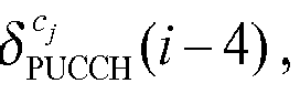
if the user equipment detects the downlink control information format encoded jointly by multiple transmitted power control commands on the subframe i-4, the user equipment taking the transmitted power control commands of the physical uplink control channel which bears the response information of the physical downlink shared channel on the component carrier cj contained in the downlink control information format as the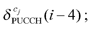
if the user equipment does not detect the downlink control information format used to schedule the physical downlink shared channel on the component carrier cj on the subframe i-4, and if the user equipment does not detect the downlink control information format encoded jointly by the multiple transmitted power control commands on the subframe i-4 either, then
- When the base station indicates multiple transmitted power control commands for the physical uplink control channel:
- there is

- or,

- Or, if the resource index of the physical uplink control channel bearing the response information of N physical downlink shared channels is mapped implicitly by the CCE index of the physical downlink control channel which schedules the physical downlink shared channel on the component carrier ch , thus


- if the user equipment detects the downlink control information format used to schedule the physical downlink shared channel on the component carrier cj on a subframe i-km , the user equipment taking the transmitted power control commands contained in the downlink control information format as the

- if the user equipment detects the downlink control information format encoded jointly by multiple transmitted power control commands on the subframe i-km , the user equipment taking the transmitted power control commands of the physical uplink control channel which bears the response information of the physical downlink shared channel on the component carrier cj contained in the downlink control information format as the

- if the user equipment does not detect the downlink control information format used to schedule the physical downlink shared channel on the component carrier cj on the subframe i - km , and if the user equipment does not detect the downlink control information format encoded jointly by multiple transmitted power control commands on the subframe i-km , then

- The function func{·} is:
- taking a minimum value, or a maximum value, or an average value, or a median value, or a sum in {·}.
- The method further comprises:
- a user equipment determining to use the accumulated value power control or absolute value power control for the physical uplink control channel according to parameters configured by an upper level signaling.
- In order to solve the above problem, the present invention further provides a base station, which is configured to:
- when response information of multiple Physical Downlink Shared Channels (PDSCH) sent on multiple component carriers is sent on one Physical Uplink Control Channel (PUCCH), indicate a unified transmitted power control command for the PUCCH; or indicate multiple transmitted power control commands for the PUCCH.
- The base station is further configured to:
- transmit the transmitted power control command in downlink control information borne by a physical downlink control channel, wherein:
- the downlink control information is a downlink control information format encoded jointly by multiple transmitted power control commands; or the downlink control information is the downlink control information format(s) used to schedule one or more PDSCHs in the multiple PDSCHs.
- In order to solve the above problem, the present invention further provides a user equipment, which is configured to:
- when a base station sends response information of multiple Physical Downlink Shared Channels (PDSCH) sent on multiple component carriers on one Physical Uplink Control Channel (PUCCH), receive a unified transmitted power control command or multiple transmitted power control commands indicated by the base station for the PUCCH, and determine a power control adjustment state g(i) of the PUCCH sent on a subframe i as an absolute value power control according to the transmitted power control command:

- or as an accumulated value power control:

- wherein, g(i-1) is the power control adjustment state, which is the absolute value power control, of the PUCCH sent on a subframe i-1, M and km are related to configurations of a system, and

- When the system is a frequency division duplex system, there are M=1, k 0=4 and

- The user equipment is further configured to: when one or more downlink control information formats used to schedule multiple physical downlink shared channels on the multiple component carriers on the subframe i are detected, take the transmitted power control commands contained in the one or more downlink control information formats as the transmitted power control command δPUCCH(i) of the physical uplink control channel indicated by the base station on the subframe i;
if a downlink control information format encoded jointly by multiple transmitted power control commands on the subframe i is detected, take corresponding transmitted power control commands contained in the downlink control information format encoded jointly by the multiple transmitted power control commands as the transmitted power control command δPUCCH(i) of the physical uplink control channel indicated by the base station on the subframe i; and
if a user equipment does not detect one or more downlink control information formats used to schedule multiple physical downlink shared channels on the multiple component carriers on the subframe i, and if the user equipment does not detect the downlink control information format encoded jointly by the multiple transmitted power control commands on the subframe i, there is δPUCCH(i)=0dB. - The user equipment is further configured to: when the system is the frequency division duplex system, determine the


- Or, if a resource index of the physical uplink control channel bearing the response information ofN physical downlink shared channels is mapped implicitly by a Control Channel Element (CCE) index of a physical downlink control channel which schedules the physical downlink shared channel on a component carrier ch , thus


- if the user equipment detects the downlink control information format used to schedule the physical downlink shared channel on the component carrier cj on a subframe i-4, the user equipment taking the transmitted power control commands contained in the downlink control information format as the
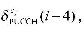
- if the user equipment detects the downlink control information format encoded jointly by multiple transmitted power control commands on the subframe i-4, the user equipment taking the transmitted power control commands of the physical uplink control channel which bears the response information of the physical downlink shared channel on the component carrier cj contained in the downlink control information format as the
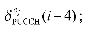
- if the user equipment does not detect the downlink control information format used to schedule the physical downlink shared channel on the component carrier cj on the subframe i-4, and does not detect the downlink control information format encoded jointly by the multiple transmitted power control commands on the subframe i-4, then

- The user equipment is further configured to: in the time division duplex system, determine the


- Or, if the resource index of the physical uplink control channel bearing the response information of N physical downlink shared channels is mapped implicitly by the CCE index of the physical downlink control channel which schedules the physical downlink shared channel on the component carrier ch, thus

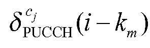
- if the user equipment detects the downlink control information format used to schedule the physical downlink shared channel on the component carrier cj on a subframe i-km , the user equipment taking the transmitted power control commands contained in the downlink control information format as the

- if the user equipment detects the downlink control information format encoded jointly by multiple transmitted power control commands on the subframe i-km , the user equipment taking the transmitted power control commands of the physical uplink control channel which bears the response information of the physical downlink shared channel on the component carrier cj contained in the downlink control information format as the

- if the user equipment does not detect the downlink control information format used to schedule the physical downlink shared channel on the component carrier cj on the subframe i -km , and does not detect the downlink control information format encoded jointly by multiple transmitted power control commands on the subframe i-km , then

- The function func{·} is:
- taking a minimum value, or a maximum value, or an average value, or a median value, or a sum in {·}.
- The user equipment is further configured to: determine to use the accumulated value power control or absolute value power control for the PUCCH according to an upper level signaling.
- The power control method, base station and user equipment for the physical uplink control channel provided by the present invention solve the problem that, in the LTE-A system using the carrier aggregation, when the response information ACK/NACK of the Physical Downlink Shared Channels (PDSCH) on multiple component carriers is sent on one Physical Uplink Control Channel (PUCCH), how the user equipment determines a current power control adjustment state of the PUCCH and then determines transmitted power of the PUCCH according to the transmitted power control commands indicated by the base station.
- The accompanying drawings are used to provide a further understanding of the present invention, constitute a part of the present invention, and explain the present invention together with the examples of the present invention, but are not intended to limit the present invention. In the drawings:
-
FIG. 1 is a schematic diagram of the format of Downlink Control Information (DCI)format 3/3A in the LTE system. -
FIG. 2 is a schematic diagram of carrier aggregation in the LTE-A system. -
FIG. 3 is a schematic diagram ofmethod 1 according to the example of the present invention. -
FIG. 4 is a schematic diagram ofmethod 2 according to the example of the present invention. - The present invention will be described in detail in combination with the examples and accompanying drawings below.
- In
step 301, when response information of multiple physical downlink shared channels sent by a base station over multiple component carriers is sent on one physical uplink control channel, the base station indicates a unified transmitted power control command for the physical uplink control channel. - The transmitted power control command is transmitted in downlink control information borne by a physical downlink control channel, including but not limited to being transmitted in Downlink Control Information (DCI)
format 3/3A encoded jointly by multiple transmitted power control commands, and is transmitted in downlink control information format(s) used to schedule one or more PDSCHs in the multiple PDSCHs, including but not limited to DCI format 1A/1B/1D/1/2A/2. - When the above transmitted power control command is transmitted in
DCI format 3/3A, the base station configures a transmitted power control index tpc-index for the Physical Uplink Control Channel (PUCCH) of a user equipment, which is used to indicate the position of the transmitted power control command in theDCI format 3/3A encoded jointly by multiple transmitted power control commands. - The Physical Downlink Control Channel (PDCCH) bearing the
DCI format 3/3A is sent on a user equipment-specific component carrier, including but not limited to being sent over a component carrier sending the physical uplink control channel (i.e. a time division duplex system), or being sent over a downlink component carrier paired with an uplink component carrier sending the physical uplink control channel (i.e. a frequency division duplex system), or being sent over an anchor Component Carrier of the user equipment. - If the user equipment detects one or more downlink control information formats used to schedule multiple physical downlink shared channels on the multiple component carriers on a subframe i, the user equipment takes the transmitted power control commands contained in the one or more downlink control information formats as the transmitted power control command δPUCCH(i) of the physical uplink control channel indicated by the base station on the subframe i;
otherwise, if the user equipment detects the downlink control information format encoded jointly by multiple transmitted power control commands on the subframe i, the user equipment takes corresponding transmitted power control commands contained in the downlink control information format encoded jointly by the multiple transmitted power control commands as the transmitted power control command δPUCCH(i) of the physical uplink control channel indicated by the base station on the subframe i; and
if the user equipment does not detect one or more downlink control information formats used to schedule multiple physical downlink shared channels on the multiple component carriers on the subframe i, or does not detect the downlink control information format encoded jointly by the multiple transmitted power control commands, then δPUCCH(i)=0dB. - In
step 401, when ACK/NACK of multiple PDSCHs sent by a base station over multiple component carriers is sent on one PUCCH, the base station indicates multiple transmitted power control commands for the physical uplink control channel. - The transmitted power control commands are transmitted in downlink control information borne by a physical downlink control channel, including but not limited to being transmitted in Downlink Control Information (DCI)
format 3/3A encoded jointly by multiple transmitted power control commands, and are transmitted in downlink control information formats used to schedule multiple PDSCHs on the multiple component carriers, including but not limited to DCI format 1A/1B/1D/1/2A/2. - If a user equipment detects a downlink control information format used to schedule a physical downlink shared channel on a component carrier cj on a subframe i, the user equipment takes the transmitted power control commands contained in the downlink control information format as the


if the user equipment does not detect the downlink control information formats used to schedule multiple physical downlink shared channels on the component carrier on the subframe i, or does not detect the downlink control information format encoded jointly by the multiple transmitted power control commands on the subframe, there is
- Thus, N transmitted power control commands used for the physical uplink control channel of the user equipment on the subframe i are


- 1) in the FDD system, the user equipment uses one function of


the function func{·} is:
taking a minimum value, or a maximum value, or an average value, or a median value, or a sum in {·};
or, if a resource index of the physical uplink control channel bearing the response information ACK/NACK of N physical downlink shared channels is mapped implicitly by a CCE index of the physical downlink control channel which schedules the physical downlink shared channel on the component carrier ch , thus
- 2) in the TDD system, the user equipment uses one function of


thus, a sum of transmitted power control commands δPUCCH of the Physical Uplink Control Channel (PUCCH) on subframes i-k 0,i-k 1,···,i-k M-1 is
wherein, values of M and km are related to uplink and downlink configurations of the system.
The function func{·} is:- taking a minimum value, or a maximum value, or an average value, or a median value, or a sum in {·};
- 3) in the TDD system, the user equipment accumulates N transmitted power control commands


- Then, one function of


- taking a minimum value, or a maximum value, or an average value, or a median value, or a sum in {·};
- or, if the resource index of the physical uplink control channel bearing the response information ACK/NACK of N physical downlink shared channels is mapped implicitly by the CCE index of the physical downlink control channel which schedules the physical downlink shared channel on the component carrier ch , thus

- In methods of 1 and 2, a power control adjustment state (i.e. a current power control adjustment state) g(i) of the Physical Uplink Control Channel (PUCCH) on the subframe i is

or
wherein, in the frequency division duplex system, M=1 and k 0=4 ; in the time division duplex system, values of M and km are related to uplink and downlink configurations of the system. - Wherein, formula (1) is called as an absolute value power control, that is:
- in the FDD system, the power control adjustment state (i.e. the current power control adjustment state) g(i) of the Physical Uplink Control Channel (PUCCH) on the subframe i is the transmitted power control command δPUCCH indicated by the base station on a subframe i-4;
- in the TDD system, the power control adjustment state (i.e. the current power control adjustment state) g(i) of the Physical Uplink Control Channel (PUCCH) on the subframe i is the sum of multiple transmitted power control commands δPUCCH indicated by the base station on the subframes i-k 0,i-k 1,···,i-k M-1.
- Formula (2) is called as an accumulated value power control, that is:
- in the FDD system, the power control adjustment state (i.e. the current power control adjustment state) g(i) of the Physical Uplink Control Channel (PUCCH) on the subframe i is an accumulated value of a power control adjustment state g(i-1) on a subframe i-1 and the transmitted power control command δPUCCH indicated by the base station on the subframe i-4;
- in the TDD system, the power control adjustment state (i.e. the current power control adjustment state) g(i) of the Physical Uplink Control Channel (PUCCH) sent on the subframe i is the accumulated value of the power control adjustment state g(i-1) on the subframe i-1 and the sum of multiple transmitted power control commands δPUCCH indicated by the base station on the subframes i-k 0, i-k 1,···,i-k M-1 .
- The user equipment determines to use the accumulated value power control or absolute value power control for the physical uplink control channel according to a user equipment-specific accumulation-enabled power control parameter configured by an upper level signaling.
- It is assumed that one LTE-A system works in a frequency division duplex mode, the LTE-A system has five downlink component carriers D1, D2, D3, D4 and D5, and five uplink component carriers U1 U2, U3, U4 and U5.
- Currently, a base station sends physical downlink shared channels to a user equipment UE1 on the four downlink component carriers D1, D2, D3 and D4, and the user equipment UE1 will send response information ACK/NACK of four PDSCHs on the uplink component carrier U1 through one physical uplink control channel. The base station indicates a unified transmitted power control command for the physical uplink control channel.
- The base station sends the transmitted power control command used for the Physical Uplink Control Channel (PUCCH) of the user equipment UE1 in a Downlink Control Information (DCI)
format 3 encoded jointly by multiple transmitted power control commands. - A Physical Downlink Control Channel (PDCCH) bearing the
DCI format 3 is sent over one user equipment-specific component carrier, for example, is sent over the downlink component carrier D1 paired with the uplink component carrier U1 which sends the Physical Uplink Control Channel (PUCCH), or is sent over an anchor component carrier D2 of the user equipment UE1. - The base station configures a transmitted power control index tpc-index for the Physical Uplink Control Channel (PUCCH) of the user equipment UE1, which is used to indicate the position of the transmitted power control command in the
DCI format 3. - When the Physical Uplink Control Channel (PUCCH) is sent, the user equipment UE1 determines to use accumulated value power control for the physical uplink control channel according to an accumulation-enabled power control parameter configured by an upper level signaling.
- A current power control adjustment state g(i) of the PUCCH is

wherein, g(i-1) is a power control adjustment state on a subframe i-1, and δPUCCH is the transmitted power control command indicated by the base station for the Physical Uplink Control Channel (PUCCH) of the user equipment UE1 on a subframe i-4. - It is assumed that one LTE-A system works in a frequency division duplex mode, the LTE-A system has five downlink component carriers D1, D2, D3, D4 and D5, and five uplink component carriers U1, U2, U3, U4 and U5.
- Currently, a base station sends four physical downlink shared channels PDSCH1, PDSCH2, PDSCH3 and PDSCH4 to a user equipment UE1 on the four downlink component carriers D1, D2, D3 and D4 respectively, and the user equipment UE1 will send response information ACK/NACK of the four PDSCHs on the uplink component carrier U1 through one Physical Uplink Control Channel (PUCCH). The base station indicates a unified transmitted power control command for the PUCCH.
- The base station transmits the transmitted power control command used for the Physical Uplink Control Channel (PUCCH) in a downlink control information format which is sent to the user equipment UE1 and used to schedule the physical downlink shared channel PDSCH1 (or PDSCH2 or PDSCH3 or PDSCH4).
- Or, the base station transmits four identical transmitted power control commands used for the Physical Uplink Control Channel (PUCCH) in four downlink control information formats respectively which are sent to the user equipment UE1 and used to schedule the physical downlink shared channels PDSCH1, PDSCH2, PDSCH3 and PDSCH4.
- When the Physical Uplink Control Channel (PUCCH) is sent, the user equipment UE1 determines to use the absolute value power control for the physical uplink control channel according to an accumulation-enabled power control parameter configured by an upper level signaling.
- A current power control adjustment state g(i) of the PUCCH is

- It is assumed that one LTE-A system works in a time division duplex mode, and the LTE-A system has five component carriers C1, C2, C3, C4 and C5.
- Currently, a base station sends physical downlink shared channels PDSCH1 and PDSCH2 to a user equipment UE1 over two downlink component carriers C1 and C2, and the user equipment UE1 will send response information ACK/NACK of the PDSCH1 and PDSCH2 on the uplink component carrier U1 through one Physical Uplink Control Channel (PUCCH). The base station indicates a unified transmitted power control command for the PUCCH.
- The base station transmits two identical transmitted power control commands used for the Physical Uplink Control Channel (PUCCH) in two downlink control information formats respectively which are sent to the user equipment UE1 and used to schedule the physical downlink shared channels PDSCH 1 and
PDSCH 2. - Or, the base station transmits one transmitted power control command used for the Physical Uplink Control Channel (PUCCH) in a downlink control information format which is sent to the user equipment UE1 and used to schedule the physical downlink shared channel PDSCH1 or PDSCH2, and sends an identical transmitted power control command used for the PUCCH in Downlink Control Information (DCT)
format 3/3A encoded jointly by multiple transmitted power control commands. - When the Physical Uplink Control Channel (PUCCH) is sent, the user equipment UE1 determines to use the absolute value power control for the physical uplink control channel according to an Accumulation-enabled power control parameter configured by an upper level signaling.
- A current power control adjustment state g(i) of the PUCCH is
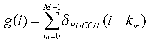
wherein, values of M and km are related to uplink and downlink configurations of the system, and δPUCCH(i-km ) is the transmitted power control command indicated by the base station for the Physical Uplink Control Channel (PUCCH) of the user equipment UE1 on a subframe i-km. - It is assumed that one LTE-A system works in a frequency division duplex mode, the LTE-A system has five downlink component carriers D1, D2, D3, D4 and D5, and five uplink component carriers U1, U2, U3, U4 and U5.
- Currently, a base station sends four physical downlink shared channels PDSCH1, PDSCH2, PDSCH3 and PDSCH4 to a user equipment UE1 over the four downlink component carriers D1, D2, D3 and D4 respectively, and the user equipment UE1 will send response information ACK/NACK of the four PDSCHs over the uplink component carrier U1 through one Physical Uplink Control Channel (PUCCH). The base station indicates multiple transmitted power control commands for the PUCCH.
- The base station transmits four transmitted power control commands, which are respectively

- The user equipment takes a maximum value in


or, if a resource index of the Physical Uplink Control Channel (PUCCH) is mapped implicitly by a CCE index of the physical downlink control channel which schedules the physical downlink shared channel PDSCH1 on the downlink component carrier D1, thus
- When the Physical Uplink Control Channel (PUCCH) is sent, the user equipment UE1 determines to use the absolute value power control for the physical uplink control channel according to an accumulation-enabled power control parameter configured by an upper level signaling.
- A current power control adjustment state g(i) of the PUCCH is

wherein, δPUCCH is the transmitted power control command indicated by the base station for the Physical Uplink Control Channel (PUCCH) of the user equipment UE1 on a subframe i-4. - It is assumed that one LTE-A system works in a time division duplex mode, and the LTE-A system has five component carriers C1, C2, C3, C4 and C5.
- Currently, a base station sends physical downlink shared channels PDSCH1, PDSCH2, PDSCH3, PDSCH4 and PDSCH5 to a user equipment UE1 over five downlink component carriers C1, C2, C3, C4 and C5, and the user equipment UE1 will send response information ACK/NACK of the PDSCH1, PDSCH2, PDSCH3, PDSCH4 and PDSCH5 over the uplink component carrier U1 through two physical uplink control channels PDCCH1 and PDCCH2 respectively. The base station indicates multiple transmitted power control commands for the physical uplink control channels PDCCH1 and PDCCH2.
- The base station transmits three transmitted power control commands of


- The user equipment takes an average value of


- The user equipment takes an average value of


- Thus, sums of transmitted power control commands of the physical uplink control channels PDCCH1 and PDCCH2 on the subframes i-k 0,i-k 1,···, i-k M-1 are respectively:


wherein, values of M and km are related to uplink and downlink configurations of the system. - When the physical uplink control channels PUCCH1 and PUCCH2 are sent, the user equipment UE1 determines to use the accumulated value power control for the physical uplink control channel according to an Accumulation-enabled power control parameter configured by an upper level signaling.
- Current power control adjustment states g 1(i) and g 2(i) of the PUCCH1 and PUCCH2 are respectively:


- It is assumed that one LTE-A system works in a time division duplex mode, and the LTE-A system has five component carriers C1, C2, C3, C4 and C5.
- Currently, a base station sends physical downlink shared channels PDSCH1, PDSCH2, PDSCH3, PDSCH4 and PDSCH5 to a user equipment UE1 over five downlink component carriers C1, C2, C3, C4 and C5, and the user equipment UE1 will send response information ACK/NACK of the PDSCH1, PDSCH2, PDSCH3, PDSCH4 and PDSCH5 over the U1 through two physical uplink control channels PDCCH1 and PDCCH2 respectively. The base station indicates multiple transmitted power control commands for the physical uplink control channels PDCCH1 and PDCCH2.
- The base station transmits four transmitted power control commands of


format 3/3A encoded jointly by multiple transmitted power control commands. - The user equipment accumulates five transmitted power control commands on the subframes i-k 0,i-k 1,···,i-k M-1 respectively:

- Then, a minimum value in


- Or, if a resource index of the PUCCH1 is mapped implicitly by a CCE index of the physical downlink control channel which schedules the physical downlink shared channel PDSCH3 on the component carrier C3, thus

if a resource index of the PUCCH2 is mapped implicitly by the CCE index of the physical downlink control channel which schedules the physical downlink shared channel PDSCH5 on the component carrier C5, thus
- When the physical uplink control channels PUCCH1 and PUCCH2 are sent, the user equipment UE1 determines to use the absolute value power control for the physical uplink control channel according to an accumulation-enabled power control parameter configured by an upper level signaling.
- Current power control adjustment states g(i) of the PUCCH1 and PUCCH2 are


wherein, values of M and km are related to uplink and downlink configurations of the system. - The ordinary person skilled in the art can understand that all or part of the steps in the above method can be completed by a program instructing related hardware, and the program can be stored in a computer readable memory medium, such as a read-only memory, disk or optical disk and so on. Alternatively, all or part of the steps of the above examples also can be implemented by using one or multiple integrated circuits. Correspondingly, each module/unit in the above examples can be implemented in a form of hardware, and also can be implemented in a form of software function module. The present invention is not limited to any combination of hardware and software in a specific form.
- The above description is only the examples of the present invention, which is not used to limit the present invention. The present invention can have various modifications and changes for the skilled in the art. All the modifications, equivalent substitutions, and improvements, etc. made within the spirit and principle of the present invention shall fall into the scope of the claims of the present invention.
- With the present invention, in the LTE-A system adopting the carrier aggregation, when response information ACK/NACK of Physical Downlink Shared Channels (PDSCH) on multiple component carriers is sent on one Physical Uplink Control Channel (PUCCH), the problem that how a user equipment determines a current power control adjustment state of the PUCCH and then determines transmitted power of the PUCCH according to the transmitted power control commands indicated by the base station is solved.
Claims (21)
- A power control method for a Physical Uplink Control Channel, comprising:when response information of multiple Physical Downlink Shared Channels (PDSCH) sent by a base station over multiple component carriers is sent on one Physical Uplink Control Channel (PUCCH), the base station indicating a unified transmitted power control command for the Physical Uplink Control Channel; or, the base station indicating multiple transmitted power control commands for the Physical Uplink Control Channel.
- The method according to claim 1, wherein:the transmitted power control command is transmitted in downlink control information borne by a Physical Downlink Control Channel (PDCCH); wherein,the downlink control information is a downlink control information format encoded jointly by multiple transmitted power control commands; or, the downlink control information is a downlink control information format/downlink control information formats used to schedule one or more PDSCHs in the multiple PDSCHs.
- The method according to claim 2, wherein:when the downlink control information is the downlink control information format encoded jointly by multiple transmitted power control commands, the method further comprises: the base station configuring a transmitted power control index for the PUCCH, which is used to indicate a position of the transmitted power control command in the downlink control information format encoded jointly by the multiple transmitted power control commands.
- The method according to claim 2, wherein:when the downlink control information is the downlink control information format encoded jointly by multiple transmitted power control commands, the method further comprises: sending the physical downlink control channel bearing the downlink control information format encoded jointly by the multiple transmitted power control commands over a user equipment-specific component carrier; wherein,the specific component carrier comprises: a component carrier sending the physical uplink control channel, or a downlink component carrier paired with an uplink component carrier sending the physical uplink control channel, or an anchor component carrier of the user equipment.
- The method according to claim 1, wherein:the base station sends a power control adjustment state g(i) of the PUCCH on a subframe i;the power control adjustment state g(i) is an absolute value transmitted power control:
 or the power control adjustment state g(i) is an accumulated value power control:
 wherein, g(i-1) is the power control adjustment state of the PUCCH on a subframe i-1, M and km are related to configurations of a system, and
- The method according to claim 5, wherein, when the system is a frequency division duplex system, then M=1, k 0=4 and the

- The method according to claim 5, wherein, when the system is a time division duplex system, values of M and km are related to uplink and downlink configurations of the time division duplex system.
- The method according to claim 1 or 6 or 7, wherein, when the base station indicates the unified transmitted power control command for the physical uplink control channel, the method further comprises:if a user equipment detects one or more downlink control information formats used to schedule multiple physical downlink shared channels on the multiple component carriers on the subframe i, the user equipment taking the transmitted power control commands contained in the one or more downlink control information formats as the transmitted power control command δPUCCH(i) of the physical uplink control channel indicated by the base station on the subframe i;if the user equipment detects the downlink control information format encoded jointly by multiple transmitted power control commands on the subframe i, the user equipment taking corresponding transmitted power control commands contained in the downlink control information format encoded jointly by the multiple transmitted power control commands as the transmitted power control command δPUCCH(i) of the physical uplink control channel indicated by the base station on the subframe i; andif the user equipment does not detect one or more downlink control information formats used to schedule multiple physical downlink shared channels on the multiple component carriers on the subframe i, and if the user equipment does not detect the downlink control information format encoded jointly by the multiple transmitted power control commands on the subframe i, then δPUCCH(i)=0dB.
- The method according to claim 6, wherein:when the base station indicates multiple transmitted power control commands for the physical uplink control channel:
 or, if a resource index of the physical uplink control channel bearing the response information ofN physical downlink shared channels is mapped implicitly by a Control Channel Element (CCE) index of the physical downlink control channel which schedules the physical downlink shared channel on a component carrier ch , thus
 wherein, func{·} represents one function; N is a number of PDSCHs transmitting the response information of the PDSCH on the PUCCH; and
 if the user equipment detects the downlink control information format used to schedule the physical downlink shared channel on the component carrier cj on a subframe i-4, the user equipment taking the transmitted power control commands contained in the downlink control information format as the
 if the user equipment detects the downlink control information format encoded jointly by multiple transmitted power control commands on the subframe i-4, the user equipment taking the transmitted power control commands of the physical uplink control channel which bears the response information of the physical downlink shared channel on the component carrier cj contained in the downlink control information format as the
 if the user equipment does not detect the downlink control information format used to schedule the physical downlink shared channel on the component carrier cj on the subframe i-4, and if the user equipment does not detect the downlink control information format encoded jointly by the multiple transmitted power control commands on the subframe i-4, then
- The method according to claim 7, wherein, when the base station indicates multiple transmitted power control commands for the physical uplink control channel:then the
 or,
or, or, if the resource index of the physical uplink control channel bearing the response information of N physical downlink shared channels is mapped implicitly by the CCE index of the physical downlink control channel which schedules the physical downlink shared channel on the component carrier ch , thus
 wherein, func{·} represents one function, and
 if the user equipment detects the downlink control information format used to schedule the physical downlink shared channel on the component carrier cj on a subframe i-km , the user equipment taking the transmitted power control commands contained in the downlink control information format as the
 if the user equipment detects the downlink control information format encoded jointly by multiple transmitted power control commands on the subframe i-km , the user equipment taking the transmitted power control commands of the physical uplink control channel which bears the response information of the physical downlink shared channel on the component carrier cj contained in the downlink control information format as the
 if the user equipment does not detect the downlink control information format used to schedule the physical downlink shared channel on the component carrier cj on the subframe i-km, and if the user equipment does not detect the downlink control information format encoded jointly by multiple transmitted power control commands on the subframe i-km either, then
- The method according to claim 9 or 10, wherein, the function Junc{·} is:taking a minimum value, or a maximum value, or an average value, or a median value, or a sum in {·}.
- The method according to claim 5, wherein, the method further comprises:the user equipment determining to use the accumulated value power control or absolute value power control for the physical uplink control channel according to parameters configured by an upper level signaling.
- A base station, which is configured to:when response information of multiple Physical Downlink Shared Channels (PDSCH) sent over multiple component carriers is sent on one Physical Uplink Control Channel (PUCCH), indicate a unified transmitted power control command for the PUCCH; or indicate multiple transmitted power control commands for the PUCCH.
- The base station according to claim 13, wherein, the base station is further configured to:transmit the transmitted power control command in downlink control information borne by a physical downlink control channel, wherein:the downlink control information is a downlink control information format encoded jointly by multiple transmitted power control commands; or the downlink control information is the downlink control information format(s) used to schedule one or more PDSCHs in the multiple PDSCHs.
- A user equipment, which is configured to:when a base station sends response information of multiple Physical Downlink Shared Channels (PDSCH) sent over multiple component carriers on one Physical Uplink Control Channel (PUCCH), receive a unified transmitted power control command or multiple transmitted power control commands indicated by the base station for the PUCCH, and determine a power control adjustment state g(i) of the PUCCH sent on a subframe i as an absolute value power control according to the transmitted power control command:
 or as an accumulated value power control:
 wherein, g(i-1) is the power control adjustment state, which is the absolute value power control, of the PUCCH sent on a subframe i-1, M and km are related to configurations of a system, and
- The user equipment according to claim 15, wherein, when the system is a frequency division duplex system, then M=1, k 0=4 and

- The user equipment according to claim 15 or 16, wherein, the user equipment is further configured to: when one or more downlink control information formats used to schedule multiple physical downlink shared channels on the multiple component carriers on the subframe i are detected, take the transmitted power control commands contained in the one or more downlink control information formats as the transmitted power control command δPUCCH(i) of the physical uplink control channel indicated by the base station on the subframe i;
if a downlink control information format encoded jointly by multiple transmitted power control commands is detected on the subframe i, take corresponding transmitted power control commands contained in the downlink control information format encoded jointly by the multiple transmitted power control commands as the transmitted power control command δPUCCH(i) of the physical uplink control channel indicated by the base station on the subframe i; and
if a user equipment does not detect one or more downlink control information formats used to schedule multiple physical downlink shared channels on the multiple component carriers on the subframe i, and if the user equipment does not detect the downlink control information format encoded jointly by the multiple transmitted power control commands on the subframe i, then δPUCCH(i)=0dB. - The user equipment according to claim 15, wherein, the user equipment is further configured to: when the system is a frequency division duplex system, determine the


or, if a resource index of the physical uplink control channel bearing the response information ofN physical downlink shared channels is mapped implicitly by a Control Channel Element (CCE) index of a physical downlink control channel which schedules the physical downlink shared channel on a component carrier ch , thus
wherein, func{·} represents one function; N is a number of PDSCHs transmitting the response information of the PDSCHs on the PUCCH; and if the user equipment detects the downlink control information format used to schedule the physical downlink shared channel on the component carrier cj on a subframe i-4, the user equipment taking the transmitted power control commands contained in the downlink control information format as the
 if the user equipment detects the downlink control information format encoded jointly by multiple transmitted power control commands on the subframe i-4, the user equipment taking the transmitted power control commands of the physical uplink control channel which bears the response information of the physical downlink shared channel on the component carrier cj contained in the downlink control information format as the
 if the user equipment does not detect the downlink control information format used to schedule the physical downlink shared channel on the component carrier cj on the subframe i-4, and does not detect the downlink control information format encoded jointly by the multiple transmitted power control commands on the subframe i-4, then
- The user equipment according to claim 15, wherein, the user equipment is further configured to: in a time division duplex system, determine the


or,
or, if the resource index of the physical uplink control channel bearing the response information of N physical downlink shared channels is mapped implicitly by the CCE index of the physical downlink control channel which schedules the physical downlink shared channel on the component carrier ch , thus
wherein, func{·} represents one function, and if the user equipment detects the downlink control information format used to schedule the physical downlink shared channel on the component carrier cj on a subframe i-km , the user equipment taking the transmitted power control commands contained in the downlink control information format as the
 if the user equipment detects the downlink control information format encoded jointly by multiple transmitted power control commands on the subframe i-km , the user equipment taking the transmitted power control commands of the physical uplink control channel which bears the response information of the physical downlink shared channel on the component carrier cj contained in the downlink control information format as the
 if the user equipment does not detect the downlink control information format used to schedule the physical downlink shared channel on the component carrier cj on the subframe i - km , and does not detect the downlink control information format encoded jointly by multiple transmitted power control commands on the subframe i-km , then the
- The user equipment according to claim 18 or 19, wherein, the function func{·} is:taking a minimum value, or a maximum value, or an average value, or a median value, or a sum in {·}.
- The user equipment according to claim 15, wherein, the user equipment is further configured to: determine to use the accumulated value power control or absolute value power control for the PUCCH according to an upper level signaling.
Priority Applications (1)
| Application Number | Priority Date | Filing Date | Title |
|---|---|---|---|
| EP17164244.0A EP3217727A1 (en) | 2009-12-28 | 2010-06-30 | Power control method, base station and terminal for physical uplink control channel |
Applications Claiming Priority (2)
| Application Number | Priority Date | Filing Date | Title |
|---|---|---|---|
| CN200910262770.2A CN101720122B (en) | 2009-12-28 | 2009-12-28 | Method, base station and terminal for controlling power of physical uplink control channel |
| PCT/CN2010/074787 WO2011079611A1 (en) | 2009-12-28 | 2010-06-30 | Power control method, base station and terminal for physical uplink control channel |
Related Child Applications (2)
| Application Number | Title | Priority Date | Filing Date |
|---|---|---|---|
| EP17164244.0A Division-Into EP3217727A1 (en) | 2009-12-28 | 2010-06-30 | Power control method, base station and terminal for physical uplink control channel |
| EP17164244.0A Division EP3217727A1 (en) | 2009-12-28 | 2010-06-30 | Power control method, base station and terminal for physical uplink control channel |
Publications (3)
| Publication Number | Publication Date |
|---|---|
| EP2498554A1 true EP2498554A1 (en) | 2012-09-12 |
| EP2498554A4 EP2498554A4 (en) | 2015-05-06 |
| EP2498554B1 EP2498554B1 (en) | 2017-08-30 |
Family
ID=42434622
Family Applications (2)
| Application Number | Title | Priority Date | Filing Date |
|---|---|---|---|
| EP10840400.5A Active EP2498554B1 (en) | 2009-12-28 | 2010-06-30 | Power control method, base station and terminal for physical uplink control channel |
| EP17164244.0A Ceased EP3217727A1 (en) | 2009-12-28 | 2010-06-30 | Power control method, base station and terminal for physical uplink control channel |
Family Applications After (1)
| Application Number | Title | Priority Date | Filing Date |
|---|---|---|---|
| EP17164244.0A Ceased EP3217727A1 (en) | 2009-12-28 | 2010-06-30 | Power control method, base station and terminal for physical uplink control channel |
Country Status (4)
| Country | Link |
|---|---|
| US (1) | US8811324B2 (en) |
| EP (2) | EP2498554B1 (en) |
| CN (1) | CN101720122B (en) |
| WO (1) | WO2011079611A1 (en) |
Cited By (3)
| Publication number | Priority date | Publication date | Assignee | Title |
|---|---|---|---|---|
| EP2685767A4 (en) * | 2011-03-29 | 2014-01-15 | Huawei Tech Co Ltd | POWER CONTROL METHOD, USER EQUIPMENT AND BASE STATION |
| EP2685766A4 (en) * | 2011-04-02 | 2014-07-30 | Zte Corp | METHOD AND DEVICE FOR CONTROLLING POWER FOR PHYSICAL UPLINK CONTROL CHANNEL |
| EP2651166A4 (en) * | 2010-12-09 | 2014-12-10 | Sharp Kk | MOBILE STATION DEVICE, TRANSMISSION SYSTEM, TRANSMISSION METHOD, AND INTEGRATED CIRCUIT |
Families Citing this family (51)
| Publication number | Priority date | Publication date | Assignee | Title |
|---|---|---|---|---|
| CN101702823B (en) * | 2009-11-04 | 2015-05-13 | 中兴通讯股份有限公司 | Method for sending emissive power control command |
| CN101720122B (en) | 2009-12-28 | 2015-05-20 | 中兴通讯股份有限公司 | Method, base station and terminal for controlling power of physical uplink control channel |
| KR101753586B1 (en) * | 2010-02-03 | 2017-07-04 | 엘지전자 주식회사 | Apparatus and method of transmitting control information in wireless communication system |
| CN102972078B (en) * | 2010-06-11 | 2015-11-25 | 华为技术有限公司 | Uplink control information transmission |
| US8867464B2 (en) * | 2010-06-28 | 2014-10-21 | Telefonaktiebolaget Lm Ericsson (Publ) | Methods and arrangements in a wireless communication system |
| CN101895976B (en) * | 2010-07-21 | 2013-10-23 | 北京交通大学 | LTE-Advanced system-based uplink power adjustment method |
| CN101917766B (en) * | 2010-08-12 | 2015-09-16 | 中兴通讯股份有限公司 | A kind of method and system determining physical uplink control channel resource |
| JP4913896B2 (en) * | 2010-08-16 | 2012-04-11 | 株式会社エヌ・ティ・ティ・ドコモ | Mobile terminal device and wireless communication method |
| CN101969685B (en) * | 2010-09-30 | 2015-11-25 | 中兴通讯股份有限公司 | A kind of power setting method of Physical Uplink Control Channel and subscriber equipment |
| EP2445279B1 (en) | 2010-10-21 | 2018-12-05 | Lg Electronics Inc. | Method and apparatus for transmitting control information in a wireless communication system |
| KR101233186B1 (en) * | 2010-10-21 | 2013-02-15 | 엘지전자 주식회사 | Method and apparutus for transmitting control information |
| US8737257B2 (en) * | 2010-10-28 | 2014-05-27 | Lg Electronics Inc. | Method and apparatus for adjusting sound reference signal transmission power |
| US8582518B2 (en) * | 2010-11-09 | 2013-11-12 | Telefonaktiebolaget L M Ericsson (Publ) | Power control for ACK/NACK formats with carrier aggregation |
| CN102480775B (en) | 2010-11-22 | 2014-01-08 | 大唐移动通信设备有限公司 | Power control method and equipment of physical uplink control channel |
| KR101867311B1 (en) * | 2010-12-21 | 2018-07-19 | 주식회사 골드피크이노베이션즈 | Method And Apparatus For Allocating ACK/NACK Resource And ACK/NACK Signal Transmitting Method Using The Same |
| CN102083189B (en) * | 2010-12-27 | 2016-07-06 | 中兴通讯股份有限公司 | The Poewr control method of a kind of Physical Uplink Control Channel and device |
| CN102625429B (en) * | 2011-01-28 | 2016-03-30 | 华为技术有限公司 | The Poewr control method of Physical Uplink Control Channel and equipment |
| CN103493419B (en) * | 2011-05-17 | 2016-08-17 | Lg电子株式会社 | Method for sending control information and device used for the method |
| CN102790740B (en) * | 2011-05-19 | 2015-04-01 | 上海中兴软件有限责任公司 | Method and device for acquiring signal power of physical uplink control channel |
| CN105611645B (en) * | 2011-08-22 | 2019-10-22 | 华为技术有限公司 | A method for sending response information, a method for receiving it, user equipment, and a base station |
| US9497741B2 (en) * | 2011-09-26 | 2016-11-15 | Lg Electronics Inc. | Method and apparatus for transmitting and receiving uplink control information in radio access system |
| CN107070542B (en) * | 2011-11-01 | 2019-05-03 | Lg电子株式会社 | Method and its equipment for sending and receiving signal |
| CN103139888A (en) * | 2011-11-28 | 2013-06-05 | 中兴通讯股份有限公司 | Power control information transmission method and system, user equipment (UE) and network side equipment |
| WO2013127057A1 (en) * | 2012-02-27 | 2013-09-06 | Qualcomm Incorporated | Ack channel design for early termination of r99 downlink traffic |
| CN103313368B (en) * | 2012-03-16 | 2018-12-04 | 中兴通讯股份有限公司 | The Poewr control method and user equipment of Physical Uplink Control Channel |
| CN103326809B (en) * | 2012-03-22 | 2017-11-28 | 中兴通讯股份有限公司 | A kind of Notification Method and device of Physical Uplink Control Channel Power Control signaling |
| CN104584651A (en) * | 2012-08-13 | 2015-04-29 | 夏普株式会社 | Wireless communication device, wireless communication method, program, and integrated circuit |
| US9565640B2 (en) * | 2013-04-19 | 2017-02-07 | Lg Electronics Inc. | Power control method and apparatus in wireless access system |
| CN105191450B (en) * | 2013-05-09 | 2019-02-05 | 夏普株式会社 | Terminal device, communication method, and integrated circuit |
| WO2014190543A1 (en) * | 2013-05-31 | 2014-12-04 | Broadcom Corporation | Channel configuration for dual connectivity and simultaneous uplink transmission |
| CN104301979B (en) * | 2013-07-19 | 2018-05-01 | 华为技术有限公司 | A kind of method for controlling uplink transmission power of UE, device, UE and base station |
| CN105379368A (en) * | 2013-08-08 | 2016-03-02 | 联发科技股份有限公司 | State Accumulation of UE Transmit Power Adjustment in Adaptive TDD System |
| WO2015018033A1 (en) * | 2013-08-08 | 2015-02-12 | Mediatek Inc. | Uplink power control in adaptive tdd systems |
| CN104767593A (en) * | 2014-01-03 | 2015-07-08 | 中兴通讯股份有限公司 | Method and device for transmitting response messages, terminal and base station |
| CN105406952B (en) * | 2014-09-10 | 2019-06-21 | 北京信威通信技术股份有限公司 | A kind of uplink authorization methods, devices and systems |
| US10149255B2 (en) | 2015-05-01 | 2018-12-04 | Qualcomm Incorporated | Low latency uplink power control |
| CN107018562B (en) * | 2016-01-27 | 2020-06-26 | 华为技术有限公司 | Uplink power control method and device |
| WO2017142029A1 (en) * | 2016-02-19 | 2017-08-24 | 株式会社Nttドコモ | User equipment, wireless base station, and wireless communication method |
| US20170273069A1 (en) * | 2016-03-16 | 2017-09-21 | Futurewei Technologies, Inc. | System and Method for Managing Connections in a Wireless Communications System |
| CN107888267B (en) * | 2016-09-30 | 2023-11-10 | 华为技术有限公司 | Uplink power control method and device |
| GB2562367B (en) * | 2017-03-23 | 2021-03-10 | Samsung Electronics Co Ltd | Improvements in and relating to scheduling requests (SR) in a telecommunication system |
| CN108633039B (en) * | 2017-03-24 | 2023-04-28 | 中兴通讯股份有限公司 | A method and device for determining an uplink control channel |
| EP3596984B1 (en) | 2017-04-17 | 2022-07-20 | Samsung Electronics Co., Ltd. | Method and device for uplink power control |
| KR102383385B1 (en) | 2017-04-17 | 2022-04-08 | 삼성전자 주식회사 | Method and device for uplink power control |
| EP3917065A1 (en) | 2017-05-02 | 2021-12-01 | Ntt Docomo, Inc. | User terminal and radio communication method |
| CN113301635B (en) * | 2017-07-03 | 2023-06-20 | 北京三星通信技术研究有限公司 | A method and device for uplink power control |
| US11032036B2 (en) * | 2017-08-11 | 2021-06-08 | Qualcomm Incorporated | Carrier aggregation (CA) of mixed numerologies |
| CN112314012B (en) * | 2018-04-18 | 2024-01-09 | 株式会社Ntt都科摩 | Terminal, base station, system and wireless communication method |
| CN111278114B (en) * | 2018-12-27 | 2023-02-07 | 维沃移动通信有限公司 | Power control method, terminal device and network side device |
| CN111988120B (en) * | 2019-05-23 | 2022-02-25 | 华为技术有限公司 | Communication method and device |
| CN114499763B (en) * | 2022-02-23 | 2024-04-23 | 成都中科微信息技术研究院有限公司 | Method for improving uplink physical control channel performance |
Family Cites Families (16)
| Publication number | Priority date | Publication date | Assignee | Title |
|---|---|---|---|---|
| US6993342B2 (en) * | 2003-05-07 | 2006-01-31 | Motorola, Inc. | Buffer occupancy used in uplink scheduling for a communication device |
| KR100909539B1 (en) * | 2004-11-09 | 2009-07-27 | 삼성전자주식회사 | Apparatus and method for supporting various multi-antenna technologies in a broadband wireless access system using multiple antennas |
| US7889755B2 (en) * | 2005-03-31 | 2011-02-15 | Qualcomm Incorporated | HSDPA system with reduced inter-user interference |
| CN101247147B (en) * | 2007-02-13 | 2012-12-19 | 中兴通讯股份有限公司 | Power control method of physical channel mapped by high speed descending sharing channel |
| ES2402910T3 (en) * | 2008-03-13 | 2013-05-10 | Telefonaktiebolaget L M Ericsson (Publ) | Method and arrangements for controlling the power of an uplink multi-carrier in a wireless communications system |
| US8676240B2 (en) * | 2008-03-25 | 2014-03-18 | Telefonaktiebolaget L M Ericsson (Publ) | Timing of component carriers in multi-carrier wireless networks |
| JP5303638B2 (en) * | 2008-04-29 | 2013-10-02 | テレフオンアクチーボラゲット エル エム エリクソン(パブル) | Method and apparatus for controlling transmission power of multi-downlink carrier |
| CN101404527B (en) * | 2008-11-11 | 2013-06-05 | 中兴通讯股份有限公司 | Power-control parameter acquirement method and power control method |
| KR20100073976A (en) * | 2008-12-23 | 2010-07-01 | 엘지전자 주식회사 | Method and appratus of controlling uplink transmission power |
| CN101448308A (en) * | 2008-12-30 | 2009-06-03 | 中兴通讯股份有限公司 | Method for controlling physical uplink shared channel transmission power |
| CN101505498B (en) * | 2009-03-17 | 2014-02-05 | 中兴通讯股份有限公司 | Downlink control information sending method, related system and apparatus |
| CN101594683B (en) * | 2009-06-19 | 2014-03-19 | 中兴通讯股份有限公司南京分公司 | Signal transmission method and system under carrier aggregation |
| CN101662833A (en) * | 2009-09-29 | 2010-03-03 | 中兴通讯股份有限公司 | Selection method and device of component carrier of uplink hybrid repeat feedback information |
| CN101702823B (en) | 2009-11-04 | 2015-05-13 | 中兴通讯股份有限公司 | Method for sending emissive power control command |
| WO2011078631A2 (en) * | 2009-12-27 | 2011-06-30 | 엘지전자 주식회사 | Method and apparatus for controlling uplink transmission power in a multi-carrier wireless communication system |
| CN101720122B (en) | 2009-12-28 | 2015-05-20 | 中兴通讯股份有限公司 | Method, base station and terminal for controlling power of physical uplink control channel |
-
2009
- 2009-12-28 CN CN200910262770.2A patent/CN101720122B/en active Active
-
2010
- 2010-06-30 EP EP10840400.5A patent/EP2498554B1/en active Active
- 2010-06-30 US US13/513,088 patent/US8811324B2/en active Active
- 2010-06-30 WO PCT/CN2010/074787 patent/WO2011079611A1/en not_active Ceased
- 2010-06-30 EP EP17164244.0A patent/EP3217727A1/en not_active Ceased
Cited By (5)
| Publication number | Priority date | Publication date | Assignee | Title |
|---|---|---|---|---|
| EP2651166A4 (en) * | 2010-12-09 | 2014-12-10 | Sharp Kk | MOBILE STATION DEVICE, TRANSMISSION SYSTEM, TRANSMISSION METHOD, AND INTEGRATED CIRCUIT |
| EP2685767A4 (en) * | 2011-03-29 | 2014-01-15 | Huawei Tech Co Ltd | POWER CONTROL METHOD, USER EQUIPMENT AND BASE STATION |
| US9439154B2 (en) | 2011-03-29 | 2016-09-06 | Huawei Technologies Co., Ltd. | Power control method, user equipment, and base station for carrier aggregation with different configurations |
| EP2685766A4 (en) * | 2011-04-02 | 2014-07-30 | Zte Corp | METHOD AND DEVICE FOR CONTROLLING POWER FOR PHYSICAL UPLINK CONTROL CHANNEL |
| US9198136B2 (en) | 2011-04-02 | 2015-11-24 | Zte Corporation | Physical uplink control channel power control method and apparatus |
Also Published As
| Publication number | Publication date |
|---|---|
| US8811324B2 (en) | 2014-08-19 |
| WO2011079611A1 (en) | 2011-07-07 |
| CN101720122B (en) | 2015-05-20 |
| CN101720122A (en) | 2010-06-02 |
| EP2498554B1 (en) | 2017-08-30 |
| EP3217727A1 (en) | 2017-09-13 |
| EP2498554A4 (en) | 2015-05-06 |
| US20120236767A1 (en) | 2012-09-20 |
Similar Documents
| Publication | Publication Date | Title |
|---|---|---|
| US8811324B2 (en) | Power control method, base station and terminal for physical uplink control channel | |
| US9198136B2 (en) | Physical uplink control channel power control method and apparatus | |
| US8711722B2 (en) | Method for processing power headroom and terminal thereof | |
| CN101808360B (en) | A kind of report method of subscriber equipment total power margin and subscriber equipment | |
| EP3942868B1 (en) | Method for determining a transmission power of an uplink transmission | |
| CN101702823B (en) | Method for sending emissive power control command | |
| US9668220B2 (en) | Method and apparatus for controlling uplink power | |
| CN102549945B (en) | Method for power headroom reporting | |
| EP2523414A1 (en) | Method and device for reporting maximum power of carrier in carrier aggregation scenario | |
| EP2685767B1 (en) | Power control method, user equipment and base station | |
| CN115348655B (en) | A method and device for reporting power head space | |
| US10588095B2 (en) | Power usage state information transmission method and apparatus | |
| CN101820672B (en) | Power control method and device of physical uplink control channel | |
| CN103313368A (en) | Power control method for physical uplink control channel and user equipment | |
| CN101969685A (en) | Power setting method for physical uplink control channel and user equipment | |
| CN102752838B (en) | Extension carrier power control method and subscriber equipment | |
| CN106559865A (en) | The method for carrying out power headroom reporting (PHR) is, the method and apparatus for determining power headroom | |
| CN104619032B (en) | Method and apparatus for transmitting and acquiring power headroom report | |
| CN101945424B (en) | A kind of method for reporting of margin of power and subscriber equipment | |
| CN101883417B (en) | The method and device that power climbing space is arranged |
Legal Events
| Date | Code | Title | Description |
|---|---|---|---|
| PUAI | Public reference made under article 153(3) epc to a published international application that has entered the european phase |
Free format text: ORIGINAL CODE: 0009012 |
|
| 17P | Request for examination filed |
Effective date: 20120608 |
|
| AK | Designated contracting states |
Kind code of ref document: A1 Designated state(s): AL AT BE BG CH CY CZ DE DK EE ES FI FR GB GR HR HU IE IS IT LI LT LU LV MC MK MT NL NO PL PT RO SE SI SK SM TR |
|
| DAX | Request for extension of the european patent (deleted) | ||
| RA4 | Supplementary search report drawn up and despatched (corrected) |
Effective date: 20150402 |
|
| RIC1 | Information provided on ipc code assigned before grant |
Ipc: H04W 52/34 20090101ALI20150327BHEP Ipc: H04W 52/14 20090101AFI20150327BHEP |
|
| 17Q | First examination report despatched |
Effective date: 20160120 |
|
| GRAP | Despatch of communication of intention to grant a patent |
Free format text: ORIGINAL CODE: EPIDOSNIGR1 |
|
| INTG | Intention to grant announced |
Effective date: 20170322 |
|
| GRAS | Grant fee paid |
Free format text: ORIGINAL CODE: EPIDOSNIGR3 |
|
| GRAA | (expected) grant |
Free format text: ORIGINAL CODE: 0009210 |
|
| AK | Designated contracting states |
Kind code of ref document: B1 Designated state(s): AL AT BE BG CH CY CZ DE DK EE ES FI FR GB GR HR HU IE IS IT LI LT LU LV MC MK MT NL NO PL PT RO SE SI SK SM TR |
|
| REG | Reference to a national code |
Ref country code: GB Ref legal event code: FG4D |
|
| REG | Reference to a national code |
Ref country code: CH Ref legal event code: EP |
|
| REG | Reference to a national code |
Ref country code: AT Ref legal event code: REF Ref document number: 924770 Country of ref document: AT Kind code of ref document: T Effective date: 20170915 |
|
| REG | Reference to a national code |
Ref country code: IE Ref legal event code: FG4D |
|
| REG | Reference to a national code |
Ref country code: DE Ref legal event code: R096 Ref document number: 602010044913 Country of ref document: DE |
|
| REG | Reference to a national code |
Ref country code: NL Ref legal event code: MP Effective date: 20170830 |
|
| REG | Reference to a national code |
Ref country code: LT Ref legal event code: MG4D |
|
| REG | Reference to a national code |
Ref country code: AT Ref legal event code: MK05 Ref document number: 924770 Country of ref document: AT Kind code of ref document: T Effective date: 20170830 |
|
| PG25 | Lapsed in a contracting state [announced via postgrant information from national office to epo] |
Ref country code: LT Free format text: LAPSE BECAUSE OF FAILURE TO SUBMIT A TRANSLATION OF THE DESCRIPTION OR TO PAY THE FEE WITHIN THE PRESCRIBED TIME-LIMIT Effective date: 20170830 Ref country code: FI Free format text: LAPSE BECAUSE OF FAILURE TO SUBMIT A TRANSLATION OF THE DESCRIPTION OR TO PAY THE FEE WITHIN THE PRESCRIBED TIME-LIMIT Effective date: 20170830 Ref country code: NO Free format text: LAPSE BECAUSE OF FAILURE TO SUBMIT A TRANSLATION OF THE DESCRIPTION OR TO PAY THE FEE WITHIN THE PRESCRIBED TIME-LIMIT Effective date: 20171130 Ref country code: SE Free format text: LAPSE BECAUSE OF FAILURE TO SUBMIT A TRANSLATION OF THE DESCRIPTION OR TO PAY THE FEE WITHIN THE PRESCRIBED TIME-LIMIT Effective date: 20170830 Ref country code: AT Free format text: LAPSE BECAUSE OF FAILURE TO SUBMIT A TRANSLATION OF THE DESCRIPTION OR TO PAY THE FEE WITHIN THE PRESCRIBED TIME-LIMIT Effective date: 20170830 Ref country code: HR Free format text: LAPSE BECAUSE OF FAILURE TO SUBMIT A TRANSLATION OF THE DESCRIPTION OR TO PAY THE FEE WITHIN THE PRESCRIBED TIME-LIMIT Effective date: 20170830 |
|
| PG25 | Lapsed in a contracting state [announced via postgrant information from national office to epo] |
Ref country code: IS Free format text: LAPSE BECAUSE OF FAILURE TO SUBMIT A TRANSLATION OF THE DESCRIPTION OR TO PAY THE FEE WITHIN THE PRESCRIBED TIME-LIMIT Effective date: 20171230 Ref country code: GR Free format text: LAPSE BECAUSE OF FAILURE TO SUBMIT A TRANSLATION OF THE DESCRIPTION OR TO PAY THE FEE WITHIN THE PRESCRIBED TIME-LIMIT Effective date: 20171201 Ref country code: BG Free format text: LAPSE BECAUSE OF FAILURE TO SUBMIT A TRANSLATION OF THE DESCRIPTION OR TO PAY THE FEE WITHIN THE PRESCRIBED TIME-LIMIT Effective date: 20171130 Ref country code: LV Free format text: LAPSE BECAUSE OF FAILURE TO SUBMIT A TRANSLATION OF THE DESCRIPTION OR TO PAY THE FEE WITHIN THE PRESCRIBED TIME-LIMIT Effective date: 20170830 Ref country code: ES Free format text: LAPSE BECAUSE OF FAILURE TO SUBMIT A TRANSLATION OF THE DESCRIPTION OR TO PAY THE FEE WITHIN THE PRESCRIBED TIME-LIMIT Effective date: 20170830 |
|
| PG25 | Lapsed in a contracting state [announced via postgrant information from national office to epo] |
Ref country code: NL Free format text: LAPSE BECAUSE OF FAILURE TO SUBMIT A TRANSLATION OF THE DESCRIPTION OR TO PAY THE FEE WITHIN THE PRESCRIBED TIME-LIMIT Effective date: 20170830 |
|
| PG25 | Lapsed in a contracting state [announced via postgrant information from national office to epo] |
Ref country code: RO Free format text: LAPSE BECAUSE OF FAILURE TO SUBMIT A TRANSLATION OF THE DESCRIPTION OR TO PAY THE FEE WITHIN THE PRESCRIBED TIME-LIMIT Effective date: 20170830 Ref country code: CZ Free format text: LAPSE BECAUSE OF FAILURE TO SUBMIT A TRANSLATION OF THE DESCRIPTION OR TO PAY THE FEE WITHIN THE PRESCRIBED TIME-LIMIT Effective date: 20170830 Ref country code: DK Free format text: LAPSE BECAUSE OF FAILURE TO SUBMIT A TRANSLATION OF THE DESCRIPTION OR TO PAY THE FEE WITHIN THE PRESCRIBED TIME-LIMIT Effective date: 20170830 Ref country code: PL Free format text: LAPSE BECAUSE OF FAILURE TO SUBMIT A TRANSLATION OF THE DESCRIPTION OR TO PAY THE FEE WITHIN THE PRESCRIBED TIME-LIMIT Effective date: 20170830 |
|
| PG25 | Lapsed in a contracting state [announced via postgrant information from national office to epo] |
Ref country code: SK Free format text: LAPSE BECAUSE OF FAILURE TO SUBMIT A TRANSLATION OF THE DESCRIPTION OR TO PAY THE FEE WITHIN THE PRESCRIBED TIME-LIMIT Effective date: 20170830 Ref country code: IT Free format text: LAPSE BECAUSE OF FAILURE TO SUBMIT A TRANSLATION OF THE DESCRIPTION OR TO PAY THE FEE WITHIN THE PRESCRIBED TIME-LIMIT Effective date: 20170830 Ref country code: EE Free format text: LAPSE BECAUSE OF FAILURE TO SUBMIT A TRANSLATION OF THE DESCRIPTION OR TO PAY THE FEE WITHIN THE PRESCRIBED TIME-LIMIT Effective date: 20170830 Ref country code: SM Free format text: LAPSE BECAUSE OF FAILURE TO SUBMIT A TRANSLATION OF THE DESCRIPTION OR TO PAY THE FEE WITHIN THE PRESCRIBED TIME-LIMIT Effective date: 20170830 |
|
| REG | Reference to a national code |
Ref country code: DE Ref legal event code: R097 Ref document number: 602010044913 Country of ref document: DE |
|
| REG | Reference to a national code |
Ref country code: FR Ref legal event code: PLFP Year of fee payment: 9 |
|
| PLBE | No opposition filed within time limit |
Free format text: ORIGINAL CODE: 0009261 |
|
| STAA | Information on the status of an ep patent application or granted ep patent |
Free format text: STATUS: NO OPPOSITION FILED WITHIN TIME LIMIT |
|
| 26N | No opposition filed |
Effective date: 20180531 |
|
| PG25 | Lapsed in a contracting state [announced via postgrant information from national office to epo] |
Ref country code: SI Free format text: LAPSE BECAUSE OF FAILURE TO SUBMIT A TRANSLATION OF THE DESCRIPTION OR TO PAY THE FEE WITHIN THE PRESCRIBED TIME-LIMIT Effective date: 20170830 |
|
| REG | Reference to a national code |
Ref country code: CH Ref legal event code: PL |
|
| REG | Reference to a national code |
Ref country code: BE Ref legal event code: MM Effective date: 20180630 |
|
| PG25 | Lapsed in a contracting state [announced via postgrant information from national office to epo] |
Ref country code: LU Free format text: LAPSE BECAUSE OF NON-PAYMENT OF DUE FEES Effective date: 20180630 Ref country code: MC Free format text: LAPSE BECAUSE OF FAILURE TO SUBMIT A TRANSLATION OF THE DESCRIPTION OR TO PAY THE FEE WITHIN THE PRESCRIBED TIME-LIMIT Effective date: 20170830 |
|
| REG | Reference to a national code |
Ref country code: IE Ref legal event code: MM4A |
|
| PG25 | Lapsed in a contracting state [announced via postgrant information from national office to epo] |
Ref country code: IE Free format text: LAPSE BECAUSE OF NON-PAYMENT OF DUE FEES Effective date: 20180630 Ref country code: CH Free format text: LAPSE BECAUSE OF NON-PAYMENT OF DUE FEES Effective date: 20180630 Ref country code: LI Free format text: LAPSE BECAUSE OF NON-PAYMENT OF DUE FEES Effective date: 20180630 |
|
| PG25 | Lapsed in a contracting state [announced via postgrant information from national office to epo] |
Ref country code: BE Free format text: LAPSE BECAUSE OF NON-PAYMENT OF DUE FEES Effective date: 20180630 |
|
| PG25 | Lapsed in a contracting state [announced via postgrant information from national office to epo] |
Ref country code: MT Free format text: LAPSE BECAUSE OF NON-PAYMENT OF DUE FEES Effective date: 20180630 |
|
| PG25 | Lapsed in a contracting state [announced via postgrant information from national office to epo] |
Ref country code: TR Free format text: LAPSE BECAUSE OF FAILURE TO SUBMIT A TRANSLATION OF THE DESCRIPTION OR TO PAY THE FEE WITHIN THE PRESCRIBED TIME-LIMIT Effective date: 20170830 |
|
| PG25 | Lapsed in a contracting state [announced via postgrant information from national office to epo] |
Ref country code: PT Free format text: LAPSE BECAUSE OF FAILURE TO SUBMIT A TRANSLATION OF THE DESCRIPTION OR TO PAY THE FEE WITHIN THE PRESCRIBED TIME-LIMIT Effective date: 20170830 Ref country code: HU Free format text: LAPSE BECAUSE OF FAILURE TO SUBMIT A TRANSLATION OF THE DESCRIPTION OR TO PAY THE FEE WITHIN THE PRESCRIBED TIME-LIMIT; INVALID AB INITIO Effective date: 20100630 |
|
| PG25 | Lapsed in a contracting state [announced via postgrant information from national office to epo] |
Ref country code: CY Free format text: LAPSE BECAUSE OF FAILURE TO SUBMIT A TRANSLATION OF THE DESCRIPTION OR TO PAY THE FEE WITHIN THE PRESCRIBED TIME-LIMIT Effective date: 20170830 Ref country code: MK Free format text: LAPSE BECAUSE OF NON-PAYMENT OF DUE FEES Effective date: 20170830 |
|
| PG25 | Lapsed in a contracting state [announced via postgrant information from national office to epo] |
Ref country code: AL Free format text: LAPSE BECAUSE OF FAILURE TO SUBMIT A TRANSLATION OF THE DESCRIPTION OR TO PAY THE FEE WITHIN THE PRESCRIBED TIME-LIMIT Effective date: 20170830 |
|
| P01 | Opt-out of the competence of the unified patent court (upc) registered |
Effective date: 20230530 |
|
| PGFP | Annual fee paid to national office [announced via postgrant information from national office to epo] |
Ref country code: DE Payment date: 20250507 Year of fee payment: 16 |
|
| PGFP | Annual fee paid to national office [announced via postgrant information from national office to epo] |
Ref country code: GB Payment date: 20250508 Year of fee payment: 16 |
|
| PGFP | Annual fee paid to national office [announced via postgrant information from national office to epo] |
Ref country code: FR Payment date: 20250508 Year of fee payment: 16 |