EP2498360A1 - DC electrical power system - Google Patents
DC electrical power system Download PDFInfo
- Publication number
- EP2498360A1 EP2498360A1 EP20120154844 EP12154844A EP2498360A1 EP 2498360 A1 EP2498360 A1 EP 2498360A1 EP 20120154844 EP20120154844 EP 20120154844 EP 12154844 A EP12154844 A EP 12154844A EP 2498360 A1 EP2498360 A1 EP 2498360A1
- Authority
- EP
- European Patent Office
- Prior art keywords
- converter
- electrical power
- extending
- fault
- earth
- Prior art date
- Legal status (The legal status is an assumption and is not a legal conclusion. Google has not performed a legal analysis and makes no representation as to the accuracy of the status listed.)
- Granted
Links
Images

Classifications
-
- H—ELECTRICITY
- H02—GENERATION; CONVERSION OR DISTRIBUTION OF ELECTRIC POWER
- H02H—EMERGENCY PROTECTIVE CIRCUIT ARRANGEMENTS
- H02H3/00—Emergency protective circuit arrangements for automatic disconnection directly responsive to an undesired change from normal electric working condition with or without subsequent reconnection ; integrated protection
- H02H3/16—Emergency protective circuit arrangements for automatic disconnection directly responsive to an undesired change from normal electric working condition with or without subsequent reconnection ; integrated protection responsive to fault current to earth, frame or mass
-
- H—ELECTRICITY
- H02—GENERATION; CONVERSION OR DISTRIBUTION OF ELECTRIC POWER
- H02H—EMERGENCY PROTECTIVE CIRCUIT ARRANGEMENTS
- H02H3/00—Emergency protective circuit arrangements for automatic disconnection directly responsive to an undesired change from normal electric working condition with or without subsequent reconnection ; integrated protection
- H02H3/08—Emergency protective circuit arrangements for automatic disconnection directly responsive to an undesired change from normal electric working condition with or without subsequent reconnection ; integrated protection responsive to excess current
- H02H3/087—Emergency protective circuit arrangements for automatic disconnection directly responsive to an undesired change from normal electric working condition with or without subsequent reconnection ; integrated protection responsive to excess current for DC applications
-
- H—ELECTRICITY
- H02—GENERATION; CONVERSION OR DISTRIBUTION OF ELECTRIC POWER
- H02H—EMERGENCY PROTECTIVE CIRCUIT ARRANGEMENTS
- H02H7/00—Emergency protective circuit arrangements specially adapted for specific types of electric machines or apparatus or for sectionalised protection of cable or line systems, and effecting automatic switching in the event of an undesired change from normal working conditions
- H02H7/26—Sectionalised protection of cable or line systems, e.g. for disconnecting a section on which a short-circuit, earth fault, or arc discharge has occured
- H02H7/268—Sectionalised protection of cable or line systems, e.g. for disconnecting a section on which a short-circuit, earth fault, or arc discharge has occured for DC systems
Definitions
- the present invention relates to a DC electrical power system having protective devices for fault protection.
- a midpoint earthing arrangement can be created by using two equally rated capacitors connected in series.
- Figure 1 shows such an earthing arrangement for positive and negative supply rails 1 extending from the converter interface 2 of a power generator 3.
- the earthing arrangement comprises a line extending between the supply rails, with two equally rated capacitors C connected in series on the line, and the earth connection located between the capacitors.
- the earth arrangement may typically comprise one solid earth connection in conjunction with multiple high-impedance earth connections. This provides multiple earth points whilst preventing circulating earth currents (which can result from the effects of converter switching).
- DC systems offer advantages over AC systems, but their adoption may be restricted due to the size and weight burden of the required protection devices.
- both fuses and circuit breakers can interrupt either alternating current (AC) or direct current (DC), but a DC circuit breaker must usually be considerably larger than an AC breaker for a given interrupting current rating. This is because DC fault currents do not have a natural current zero to aid the extinction of the fault current.
- An AC breaker can make use of the two current reversals per electrical cycle (i.e. a reversal every 10ms on a 50Hz system), the fault arc between the switch contacts effectively extinguishing as the contacts are drawn apart and the current passes through zero. DC currents do not have such reversals to aid current interruption, and this results in DC circuit breakers being larger and heavier than equivalent AC equipment.
- the present invention provides a DC electrical power system having:
- the second protective device by locating the second protective device on the earthing arrangement it is possible to share the second protective device with other DC electrical power systems which are networked with the first power system. This allows an overall reduction in the number of protective devices, which provides corresponding weight and space savings.
- the power system may have any one or, to the extent that they are compatible, any combination of the following optional features.
- the power system has only the one protective device on the supply rails. In this way, lower losses can be obtained, allowing the power system to operate at a higher efficiency.
- the power generator converter system may comprise a power generator and a converter interface for the power generator, the supply rails extending from the converter interface.
- the power generator converter system may comprise two or more power generators and respective converter interfaces for the power generators, the converter interfaces being connected in series, the positive supply rail extending from an end one of the converter interfaces, and the negative supply rail extending from the other end one of the converter interfaces.
- the earthing arrangement may include a pair of equally rated capacitances connected in series on a line extending between the supply rails, the solid earth connection being connected to the line between the capacitances.
- the earthing arrangement can connect the solid earth connection to a mid-position between the converter interfaces.
- the present invention provides a DC electrical power network having the DC electrical power system according to first aspect and further having one or more further DC electrical power systems, each further DC electrical power system having:
- the earthing arrangement may include one or more high-impedance earth connections.
- the DC electrical power system of the first aspect or the DC electrical power network of the second aspect may be for non-land-based use, e.g. for use in an off-shore facility or aerospace vehicle, such locations typically being more sensitive to size and weight burdens.
- the present invention provides the use in an off-shore facility or aerospace vehicle of the DC electrical power network of the first aspect or of the DC electrical power network of the second aspect.
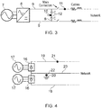
- FIG. 3 shows a DC electrical power system having a protection arrangement according to a first embodiment of the present invention.
- the power system has a power generator converter system in which a converter interface 6 (e.g. a power electronic converter) converts AC power from an AC generator 7 into DC power.
- a converter interface 6 e.g. a power electronic converter
- Positive and negative supply rails 6 extend from the converter interface to join the power system to an electrical network, which can include other power systems and loads.
- the power system has a midpoint earthing arrangement in which a line 8 extends between the supply rails 9, equally rated capacitors C being connected in series on the line.
- a solid earth connection 10 is connected to the line between the capacitors.
- the protection arrangement for the power system comprises a first protective device 11, such as a circuit breaker, which is located on one of the supply rails 9.
- the protection arrangement also comprises a second protective device 12 which is located at the solid earth connection.
- first protective device When the first protective device is operated, current flow along the respective supply line is interrupted.
- second protective device When the second protective device is operated, current flow to earth through the solid earth connection is interrupted.
- the arrangement of the protective devices shown in Figure 3 provides the same protection functionality as the conventional arrangement of the protective devices shown in Figure 2 .
- the supply rail mounted device 11 protects against rail to rail faults and the earth connection mounted device 12 protects against rail to earth faults.
- only one protective device is hence needed, reducing the total number of devices employed.
- the potential to suffer a rail to earth fault still exists (for example due to a breakdown in component insulation).
- the solid earth connection 10 (even if not at the faulted system) provides a return path for the fault current.
- the second protective device 12 can isolate an earth fault anywhere on the network.
- the arrangement provides the following protective functionality:
- the arrangement requires fewer protective devices than the conventional approach. Therefore, even if the protective devices 11,12 are required to be of a higher rating (because, being fewer, they are required to dissipate more energy), valuable savings in system weight and size can be obtained. More specifically, for a network have N power systems, 2N protective devices would be required (one on each rail) with the conventional approach, but only (N+1) protective devices are required utilising the approach of the present invention. Additionally, by having fewer protective devices in the main current paths of each system, lower operating losses can be obtained, providing a higher network efficiency. In the context of an aerospace vehicle application, this can lead to reduced fuel consumption, increased vehicle range and/or reduced emissions for a given mission profile.
- Figure 4 shows a DC electrical power system having a protection arrangement according to a second embodiment of the present invention.
- the power system has a power generator converter system in which two converter interfaces 16 convert AC power from respective AC generators 17 into DC power.
- the converter interfaces are connected in series, one of the positive and negative supply rails 19 extends from one of the converter interfaces and the other of the positive and negative supply rails 19 extends from the other of the converter interfaces to join the power system to an electrical network.
- more converter interfaces can be connected in series, with the supply rails respectively extending from the end interfaces.
- Midpoint earthing is then obtained by connecting the solid earth connection 20 to an earth rail 23 which extends from a point between the two interfaces 16.
- a first protective device 21 is located on one of the supply rails 19, and a second protective device 22 is located at the solid earth connection.
Landscapes
- Emergency Protection Circuit Devices (AREA)
- Direct Current Feeding And Distribution (AREA)
Abstract
Description
- The present invention relates to a DC electrical power system having protective devices for fault protection.
- In DC electrical networks, e.g. for use in aircraft systems, it is known to earth the network at the midpoint of a DC power supply. This reduces the insulation voltage levels in order to avoid corona and partial discharge and also helps to minimise the possibility of insulation failure over the lifetime of the equipment. A midpoint earthing arrangement can be created by using two equally rated capacitors connected in series. For example,
Figure 1 shows such an earthing arrangement for positive andnegative supply rails 1 extending from theconverter interface 2 of apower generator 3. The earthing arrangement comprises a line extending between the supply rails, with two equally rated capacitors C connected in series on the line, and the earth connection located between the capacitors. In a DC system, the earth arrangement may typically comprise one solid earth connection in conjunction with multiple high-impedance earth connections. This provides multiple earth points whilst preventing circulating earth currents (which can result from the effects of converter switching). - As shown in
Figure 2 , conventional protection practice for DC systems of this type is to placeprotective devices 4 on each of thesupply rails 5, in this way protecting against both rail-to-rail and rail-to-earth faults within the protected zone. The approach provides the following protective functionality: - The fault current contribution to any network fault (both rail to earth and rail to rail) from both the generator (e.g. through a power electronic converter) and capacitive discharge (caused by a collapse/dip in network voltage resulting from the occurrence of the fault) can be limited.
- If current limiting technologies are employed, the protective devices can prevent significant decreases in voltage at the converter terminals, preventing increased current output from the converter in addition to preventing capacitive discharge.
- If a fault occurs between the converter and the protective devices, the operation of the protective devices can isolate the rest of the network from the fault.
- If the protection around the network is properly graded, only an earth fault between the converter and the protective devices can cause the loss of the solid earth connection from the network.
- Particularly for mobile applications or where a battery system is used, DC systems offer advantages over AC systems, but their adoption may be restricted due to the size and weight burden of the required protection devices.
- More particularly, both fuses and circuit breakers can interrupt either alternating current (AC) or direct current (DC), but a DC circuit breaker must usually be considerably larger than an AC breaker for a given interrupting current rating. This is because DC fault currents do not have a natural current zero to aid the extinction of the fault current. An AC breaker can make use of the two current reversals per electrical cycle (i.e. a reversal every 10ms on a 50Hz system), the fault arc between the switch contacts effectively extinguishing as the contacts are drawn apart and the current passes through zero. DC currents do not have such reversals to aid current interruption, and this results in DC circuit breakers being larger and heavier than equivalent AC equipment.
- Accordingly, given the potentially significant weight and size penalties of DC fault interruption technologies, it is desirable to reduce the number of protection devices employed on a DC electrical network.
- Accordingly, in a first aspect, the present invention provides a DC electrical power system having:
- a power generator converter system,
- a positive supply rail extending from the converter system,
- a negative supply rail extending from the converter system, and
- a midpoint earthing arrangement operatively connecting to the supply rails, the earthing arrangement being connected to earth by a solid earth connection;
- a first protective device on one of the supply rails which in case of a fault is operable to interrupt current flowing on that rail, and
- a second protective device on the earthing arrangement which in case of a fault is operable to interrupt current flowing to earth through the solid earth connection.
- Advantageously, by locating the second protective device on the earthing arrangement it is possible to share the second protective device with other DC electrical power systems which are networked with the first power system. This allows an overall reduction in the number of protective devices, which provides corresponding weight and space savings.
- The power system may have any one or, to the extent that they are compatible, any combination of the following optional features.
- Typically, the power system has only the one protective device on the supply rails. In this way, lower losses can be obtained, allowing the power system to operate at a higher efficiency.
- The power generator converter system may comprise a power generator and a converter interface for the power generator, the supply rails extending from the converter interface.
- Alternatively, the power generator converter system may comprise two or more power generators and respective converter interfaces for the power generators, the converter interfaces being connected in series, the positive supply rail extending from an end one of the converter interfaces, and the negative supply rail extending from the other end one of the converter interfaces.
- The earthing arrangement may include a pair of equally rated capacitances connected in series on a line extending between the supply rails, the solid earth connection being connected to the line between the capacitances.
- Alternatively, when the power generator converter system comprises two or more power generators and respective converter interfaces, the earthing arrangement can connect the solid earth connection to a mid-position between the converter interfaces.
- In a second aspect, the present invention provides a DC electrical power network having the DC electrical power system according to first aspect and further having one or more further DC electrical power systems, each further DC electrical power system having:
- a respective further power generator converter system,
- a positive supply rail extending from each further converter system, and
- a negative supply rail extending from each further converter system;
- the midpoint earthing arrangement operatively connects to the supply rails of each further converter system, and
- a further protective device is located on only one of the supply rails of each further converter system, which further protective device in case of a fault is operable to interrupt current flowing on that rail.
- The earthing arrangement may include one or more high-impedance earth connections.
- The DC electrical power system of the first aspect or the DC electrical power network of the second aspect may be for non-land-based use, e.g. for use in an off-shore facility or aerospace vehicle, such locations typically being more sensitive to size and weight burdens.
- Indeed a third aspect, the present invention provides the use in an off-shore facility or aerospace vehicle of the DC electrical power network of the first aspect or of the DC electrical power network of the second aspect.
- Embodiments of the invention will now be described by way of example with reference to the accompanying drawings in which:
-
Figure 1 shows an earthing arrangement for a DC electrical power system; -
Figure 2 shows a DC electrical power system having a conventional protection arrangement; -
Figure 3 shows a DC electrical power system having a protection arrangement according to a first embodiment of the present invention; and -
Figure 4 shows a DC electrical power system having a protection arrangement according to a second embodiment of the present invention. -
Figure 3 shows a DC electrical power system having a protection arrangement according to a first embodiment of the present invention. The power system has a power generator converter system in which a converter interface 6 (e.g. a power electronic converter) converts AC power from anAC generator 7 into DC power. Positive andnegative supply rails 6 extend from the converter interface to join the power system to an electrical network, which can include other power systems and loads. - The power system has a midpoint earthing arrangement in which a line 8 extends between the
supply rails 9, equally rated capacitors C being connected in series on the line. Asolid earth connection 10 is connected to the line between the capacitors. - The protection arrangement for the power system comprises a first
protective device 11, such as a circuit breaker, which is located on one of thesupply rails 9. The protection arrangement also comprises a secondprotective device 12 which is located at the solid earth connection. When the first protective device is operated, current flow along the respective supply line is interrupted. Likewise, when the second protective device is operated, current flow to earth through the solid earth connection is interrupted. - The arrangement of the protective devices shown in
Figure 3 provides the same protection functionality as the conventional arrangement of the protective devices shown inFigure 2 . The supply rail mounteddevice 11 protects against rail to rail faults and the earth connection mounteddevice 12 protects against rail to earth faults. For other systems within the network which have either a high impedance earth connection or no earth connection, only one protective device is hence needed, reducing the total number of devices employed. In particular, even for systems without a dedicated earth connection, the potential to suffer a rail to earth fault still exists (for example due to a breakdown in component insulation). Under such a circumstance, the solid earth connection 10 (even if not at the faulted system) provides a return path for the fault current. Hence the secondprotective device 12 can isolate an earth fault anywhere on the network. - More particularly, the arrangement provides the following protective functionality:
- The fault current contribution to any network fault (both rail to earth and rail to rail) from both the generator 7 (through the converter interface 6) and capacitive discharge (caused by a collapse/dip in network voltage resulting from the occurrence of the fault) is limited.
- If current limiting technologies are employed, the
protective devices - While the converter system will not be completely isolated from the rest of the network if a fault occurs between the converter and the protective devices, only one
supply rail 6 is left intact, making the flow of any current to the faulted system unlikely. - Any earth fault within the network will cause the earth mounted
protective device 12 to operate, providing a limited ride-through capability for the network. - Advantageously, while providing adequate protection to the network, the arrangement requires fewer protective devices than the conventional approach. Therefore, even if the
protective devices - In the event of an earth fault, the low impedance solid-earthed
connection 10 is lost. However, other high impendence earth connections can still remain intact (and there will generally be a slow shift in potential at these locations). This is in contrast to the conventional approach where the location of the fault will determine whether the solid earth connection is lost or not. - The arrangement of the protective devices shown in
Figure 3 can be employed in other situations where a midpoint earthing arrangement is used. For example,Figure 4 shows a DC electrical power system having a protection arrangement according to a second embodiment of the present invention. The power system has a power generator converter system in which twoconverter interfaces 16 convert AC power fromrespective AC generators 17 into DC power. The converter interfaces are connected in series, one of the positive and negative supply rails 19 extends from one of the converter interfaces and the other of the positive and negative supply rails 19 extends from the other of the converter interfaces to join the power system to an electrical network. In other such power systems more converter interfaces can be connected in series, with the supply rails respectively extending from the end interfaces. - Midpoint earthing is then obtained by connecting the
solid earth connection 20 to anearth rail 23 which extends from a point between the two interfaces 16. A firstprotective device 21 is located on one of the supply rails 19, and a secondprotective device 22 is located at the solid earth connection. - While the invention has been described in conjunction with the exemplary embodiments described above, many equivalent modifications and variations will be apparent to those skilled in the art when given this disclosure. Accordingly, the exemplary embodiments of the invention set forth above are considered to be illustrative and not limiting. Various changes to the described embodiments may be made without departing from the spirit and scope of the invention.
Claims (9)
- A DC electrical power system having:a power generator converter system,a positive supply rail (9, 19) extending from the converter system,a negative supply rail (9, 19) extending from the converter system, anda midpoint earthing arrangement operatively connecting to the supply rails, the earthing arrangement being connected to earth by a solid earth connection (10, 20);wherein the network further has:a first protective device (11, 21) on one of the supply rails which in case of a fault is operable to interrupt current flowing on that rail, anda second protective device (12, 22) on the earthing arrangement which in case of a fault is operable to interrupt current flowing to earth through the solid earth connection.
- A DC electrical power system according to claim 1 wherein the power generator converter system comprises a power generator (7) and a converter interface (6) for the power generator, the supply rails extending from the converter interface.
- A DC electrical power system according to claim 1 wherein the power generator converter system comprises two or more power generators (17) and respective converter interfaces (16) for the power generators, the converter interfaces being connected in series, the positive supply rail extending from an end one of the converter interfaces, and the negative supply rail extending from the other end one of the converter interfaces.
- A DC electrical power system according to any one of the previous claims,
wherein the earthing arrangement includes a pair of equally rated capacitances (C) connected in series on a line (8) extending between the supply rails, the solid earth connection being connected to the line between the capacitances. - A DC electrical power system according to claim 3, wherein the earthing arrangement connects the solid earth connection to a mid-position between the converter interfaces.
- A DC electrical power network having the DC electrical power system according to any one of the previous claims and further having one or more further DC electrical power systems, each further DC electrical power system having:a respective further power generator converter system,a positive supply rail extending from each further converter system, anda negative supply rail extending from each further converter system;wherein:the midpoint earthing arrangement operatively connects to the supply rails of each further converter system, anda further protective device is located on only one of the supply rails of each further converter system, which further protective device in case of a fault is operable to interrupt current flowing on that rail.
- A DC electrical power network according to claim 6, wherein the earthing arrangement further includes one or more high-impedance earth connections.
- A DC electrical power system according to any one of the claims 1 to 5 or a DC electrical power network according to claim 6 or 7, which is for use in an off-shore facility or aerospace vehicle.
- Use in an off-shore facility or aerospace vehicle of the DC electrical power network according to any one of the claims 1 to 5 or of the DC electrical power network according to claim 6 or 7.
Applications Claiming Priority (1)
| Application Number | Priority Date | Filing Date | Title |
|---|---|---|---|
| GB201103798A GB201103798D0 (en) | 2011-03-07 | 2011-03-07 | DC electrical power system |
Publications (2)
| Publication Number | Publication Date |
|---|---|
| EP2498360A1 true EP2498360A1 (en) | 2012-09-12 |
| EP2498360B1 EP2498360B1 (en) | 2021-04-07 |
Family
ID=43923276
Family Applications (1)
| Application Number | Title | Priority Date | Filing Date |
|---|---|---|---|
| EP12154844.0A Active EP2498360B1 (en) | 2011-03-07 | 2012-02-10 | DC electrical power system |
Country Status (3)
| Country | Link |
|---|---|
| US (1) | US8837095B2 (en) |
| EP (1) | EP2498360B1 (en) |
| GB (1) | GB201103798D0 (en) |
Cited By (1)
| Publication number | Priority date | Publication date | Assignee | Title |
|---|---|---|---|---|
| CN114552595A (en) * | 2020-11-27 | 2022-05-27 | 南京南瑞继保电气有限公司 | Control method and control device for eliminating influence of series compensator on line protection |
Families Citing this family (2)
| Publication number | Priority date | Publication date | Assignee | Title |
|---|---|---|---|---|
| GB2536894B (en) * | 2015-03-30 | 2021-06-23 | General Electric Technology Gmbh | Converters |
| EP4468549A1 (en) * | 2023-05-26 | 2024-11-27 | General Electric Technology GmbH | Improvements in relation to dynamic braking systems for bipole power transmission networks |
Citations (1)
| Publication number | Priority date | Publication date | Assignee | Title |
|---|---|---|---|---|
| US5751524A (en) * | 1997-03-10 | 1998-05-12 | Square D Company | Ground fault protection circuit for a multiple source system |
Family Cites Families (1)
| Publication number | Priority date | Publication date | Assignee | Title |
|---|---|---|---|---|
| EP2118980B1 (en) * | 2007-03-06 | 2019-09-11 | Xantrex Technology, Inc. | Bipolar dc to ac power converter with dc ground fault interrupt |
-
2011
- 2011-03-07 GB GB201103798A patent/GB201103798D0/en not_active Ceased
-
2012
- 2012-02-10 EP EP12154844.0A patent/EP2498360B1/en active Active
- 2012-02-10 US US13/370,954 patent/US8837095B2/en active Active
Patent Citations (1)
| Publication number | Priority date | Publication date | Assignee | Title |
|---|---|---|---|---|
| US5751524A (en) * | 1997-03-10 | 1998-05-12 | Square D Company | Ground fault protection circuit for a multiple source system |
Non-Patent Citations (2)
| Title |
|---|
| CHRYSANTHOS CHRYSANTHOU ET AL: "Analysis of Coordination Between Primary and Secondary Protectors", IEEE TRANSACTIONS ON POWER DELIVERY, IEEE SERVICE CENTER, NEW YORK, NY, US, vol. 12, no. 4, 1 October 1997 (1997-10-01), pages 1501 - 1507, XP011049380, ISSN: 0885-8977, DOI: 10.1109/61.634167 * |
| XU XIAO-KANG ET AL: "Study on Bipole Protection of #x00B1;800KV UHVDC System", ELECTRICAL AND CONTROL ENGINEERING (ICECE), 2010 INTERNATIONAL CONFERENCE ON, IEEE, PISCATAWAY, NJ, USA, 25 June 2010 (2010-06-25), pages 4279 - 4282, XP031797826, ISBN: 978-1-4244-6880-5, DOI: 10.1109/ICECE.2010.1039 * |
Cited By (1)
| Publication number | Priority date | Publication date | Assignee | Title |
|---|---|---|---|---|
| CN114552595A (en) * | 2020-11-27 | 2022-05-27 | 南京南瑞继保电气有限公司 | Control method and control device for eliminating influence of series compensator on line protection |
Also Published As
| Publication number | Publication date |
|---|---|
| EP2498360B1 (en) | 2021-04-07 |
| GB201103798D0 (en) | 2011-04-20 |
| US20120228949A1 (en) | 2012-09-13 |
| US8837095B2 (en) | 2014-09-16 |
Similar Documents
| Publication | Publication Date | Title |
|---|---|---|
| KR102381846B1 (en) | Series compensator and control method | |
| Fletcher et al. | Determination of protection system requirements for DC unmanned aerial vehicle electrical power networks for enhanced capability and survivability | |
| US9172248B2 (en) | Cascaded converter station and cascaded multi-terminal HVDC power transmission system | |
| US9692226B2 (en) | Circuit interruption device | |
| US9054557B2 (en) | Voltage balancing of symmetric HVDC monopole transmission lines after earth faults | |
| CN102347610B (en) | The electric power system of aircraft | |
| US20140299579A1 (en) | Dc voltage circuit breaker | |
| CN102906847B (en) | Leakage detection device with unexpected action prevention function | |
| EP2580829A1 (en) | Breaker failure protection of hvdc circuit breakers | |
| CN102082432A (en) | Cascaded converter stations and cascaded multi-terminal HVDC transmission systems | |
| CN101297448B (en) | converter station | |
| EP2887483A1 (en) | Breaker circuit configurations for multi-terminal DC systems | |
| US8643985B2 (en) | Photovoltaic bipolar to monopolar source circuit converter with frequency selective grounding | |
| JP2013247787A (en) | Photovoltaic power generation system and short circuit current detector | |
| US8837095B2 (en) | DC electrical power system | |
| EP2744062B1 (en) | A subsea system with ride-through protection | |
| JP2012065461A (en) | Surge protection device protective system and surge protection system | |
| JP2023523985A (en) | Apparatus, method and power distribution system for preventing electric shock and fire during electric leakage and ground fault | |
| US20070086141A1 (en) | Surge receptacle apparatus and power system including the same | |
| CN101297455B (en) | converter station | |
| WO2012136241A1 (en) | Fault handling during circuit breaker maintenance in a double-breaker busbar switchyard | |
| EP3416256B1 (en) | High voltage direct current converter harmonic filtering and protection system | |
| CN108616110B (en) | A protection device for AC and DC interconnection systems | |
| RU2761430C1 (en) | DEVICE FOR RESTORING FULL-PHASE VOLTAGE IN A 4-WIRE NETWORK OF 0.4/0.23 kV | |
| Chaffey et al. | Design of backup protection for the DC interconnection of adjacent point-to-point HVDC systems |
Legal Events
| Date | Code | Title | Description |
|---|---|---|---|
| PUAI | Public reference made under article 153(3) epc to a published international application that has entered the european phase |
Free format text: ORIGINAL CODE: 0009012 |
|
| AK | Designated contracting states |
Kind code of ref document: A1 Designated state(s): AL AT BE BG CH CY CZ DE DK EE ES FI FR GB GR HR HU IE IS IT LI LT LU LV MC MK MT NL NO PL PT RO RS SE SI SK SM TR |
|
| AX | Request for extension of the european patent |
Extension state: BA ME |
|
| 17P | Request for examination filed |
Effective date: 20130311 |
|
| 17Q | First examination report despatched |
Effective date: 20150615 |
|
| RAP1 | Party data changed (applicant data changed or rights of an application transferred) |
Owner name: ROLLS-ROYCE PLC |
|
| STAA | Information on the status of an ep patent application or granted ep patent |
Free format text: STATUS: EXAMINATION IS IN PROGRESS |
|
| RAP1 | Party data changed (applicant data changed or rights of an application transferred) |
Owner name: ROLLS-ROYCE PLC |
|
| GRAP | Despatch of communication of intention to grant a patent |
Free format text: ORIGINAL CODE: EPIDOSNIGR1 |
|
| STAA | Information on the status of an ep patent application or granted ep patent |
Free format text: STATUS: GRANT OF PATENT IS INTENDED |
|
| INTG | Intention to grant announced |
Effective date: 20201210 |
|
| GRAS | Grant fee paid |
Free format text: ORIGINAL CODE: EPIDOSNIGR3 |
|
| GRAA | (expected) grant |
Free format text: ORIGINAL CODE: 0009210 |
|
| STAA | Information on the status of an ep patent application or granted ep patent |
Free format text: STATUS: THE PATENT HAS BEEN GRANTED |
|
| AK | Designated contracting states |
Kind code of ref document: B1 Designated state(s): AL AT BE BG CH CY CZ DE DK EE ES FI FR GB GR HR HU IE IS IT LI LT LU LV MC MK MT NL NO PL PT RO RS SE SI SK SM TR |
|
| REG | Reference to a national code |
Ref country code: GB Ref legal event code: FG4D |
|
| REG | Reference to a national code |
Ref country code: AT Ref legal event code: REF Ref document number: 1380923 Country of ref document: AT Kind code of ref document: T Effective date: 20210415 Ref country code: CH Ref legal event code: EP |
|
| REG | Reference to a national code |
Ref country code: DE Ref legal event code: R096 Ref document number: 602012075078 Country of ref document: DE |
|
| REG | Reference to a national code |
Ref country code: IE Ref legal event code: FG4D |
|
| REG | Reference to a national code |
Ref country code: LT Ref legal event code: MG9D |
|
| REG | Reference to a national code |
Ref country code: NL Ref legal event code: MP Effective date: 20210407 Ref country code: AT Ref legal event code: MK05 Ref document number: 1380923 Country of ref document: AT Kind code of ref document: T Effective date: 20210407 |
|
| PG25 | Lapsed in a contracting state [announced via postgrant information from national office to epo] |
Ref country code: AT Free format text: LAPSE BECAUSE OF FAILURE TO SUBMIT A TRANSLATION OF THE DESCRIPTION OR TO PAY THE FEE WITHIN THE PRESCRIBED TIME-LIMIT Effective date: 20210407 Ref country code: BG Free format text: LAPSE BECAUSE OF FAILURE TO SUBMIT A TRANSLATION OF THE DESCRIPTION OR TO PAY THE FEE WITHIN THE PRESCRIBED TIME-LIMIT Effective date: 20210707 Ref country code: HR Free format text: LAPSE BECAUSE OF FAILURE TO SUBMIT A TRANSLATION OF THE DESCRIPTION OR TO PAY THE FEE WITHIN THE PRESCRIBED TIME-LIMIT Effective date: 20210407 Ref country code: FI Free format text: LAPSE BECAUSE OF FAILURE TO SUBMIT A TRANSLATION OF THE DESCRIPTION OR TO PAY THE FEE WITHIN THE PRESCRIBED TIME-LIMIT Effective date: 20210407 Ref country code: NL Free format text: LAPSE BECAUSE OF FAILURE TO SUBMIT A TRANSLATION OF THE DESCRIPTION OR TO PAY THE FEE WITHIN THE PRESCRIBED TIME-LIMIT Effective date: 20210407 Ref country code: LT Free format text: LAPSE BECAUSE OF FAILURE TO SUBMIT A TRANSLATION OF THE DESCRIPTION OR TO PAY THE FEE WITHIN THE PRESCRIBED TIME-LIMIT Effective date: 20210407 |
|
| PG25 | Lapsed in a contracting state [announced via postgrant information from national office to epo] |
Ref country code: GR Free format text: LAPSE BECAUSE OF FAILURE TO SUBMIT A TRANSLATION OF THE DESCRIPTION OR TO PAY THE FEE WITHIN THE PRESCRIBED TIME-LIMIT Effective date: 20210708 Ref country code: IS Free format text: LAPSE BECAUSE OF FAILURE TO SUBMIT A TRANSLATION OF THE DESCRIPTION OR TO PAY THE FEE WITHIN THE PRESCRIBED TIME-LIMIT Effective date: 20210807 Ref country code: LV Free format text: LAPSE BECAUSE OF FAILURE TO SUBMIT A TRANSLATION OF THE DESCRIPTION OR TO PAY THE FEE WITHIN THE PRESCRIBED TIME-LIMIT Effective date: 20210407 Ref country code: RS Free format text: LAPSE BECAUSE OF FAILURE TO SUBMIT A TRANSLATION OF THE DESCRIPTION OR TO PAY THE FEE WITHIN THE PRESCRIBED TIME-LIMIT Effective date: 20210407 Ref country code: SE Free format text: LAPSE BECAUSE OF FAILURE TO SUBMIT A TRANSLATION OF THE DESCRIPTION OR TO PAY THE FEE WITHIN THE PRESCRIBED TIME-LIMIT Effective date: 20210407 Ref country code: ES Free format text: LAPSE BECAUSE OF FAILURE TO SUBMIT A TRANSLATION OF THE DESCRIPTION OR TO PAY THE FEE WITHIN THE PRESCRIBED TIME-LIMIT Effective date: 20210407 Ref country code: NO Free format text: LAPSE BECAUSE OF FAILURE TO SUBMIT A TRANSLATION OF THE DESCRIPTION OR TO PAY THE FEE WITHIN THE PRESCRIBED TIME-LIMIT Effective date: 20210707 Ref country code: PT Free format text: LAPSE BECAUSE OF FAILURE TO SUBMIT A TRANSLATION OF THE DESCRIPTION OR TO PAY THE FEE WITHIN THE PRESCRIBED TIME-LIMIT Effective date: 20210809 Ref country code: PL Free format text: LAPSE BECAUSE OF FAILURE TO SUBMIT A TRANSLATION OF THE DESCRIPTION OR TO PAY THE FEE WITHIN THE PRESCRIBED TIME-LIMIT Effective date: 20210407 |
|
| REG | Reference to a national code |
Ref country code: DE Ref legal event code: R097 Ref document number: 602012075078 Country of ref document: DE |
|
| PG25 | Lapsed in a contracting state [announced via postgrant information from national office to epo] |
Ref country code: RO Free format text: LAPSE BECAUSE OF FAILURE TO SUBMIT A TRANSLATION OF THE DESCRIPTION OR TO PAY THE FEE WITHIN THE PRESCRIBED TIME-LIMIT Effective date: 20210407 Ref country code: EE Free format text: LAPSE BECAUSE OF FAILURE TO SUBMIT A TRANSLATION OF THE DESCRIPTION OR TO PAY THE FEE WITHIN THE PRESCRIBED TIME-LIMIT Effective date: 20210407 Ref country code: DK Free format text: LAPSE BECAUSE OF FAILURE TO SUBMIT A TRANSLATION OF THE DESCRIPTION OR TO PAY THE FEE WITHIN THE PRESCRIBED TIME-LIMIT Effective date: 20210407 Ref country code: CZ Free format text: LAPSE BECAUSE OF FAILURE TO SUBMIT A TRANSLATION OF THE DESCRIPTION OR TO PAY THE FEE WITHIN THE PRESCRIBED TIME-LIMIT Effective date: 20210407 Ref country code: SK Free format text: LAPSE BECAUSE OF FAILURE TO SUBMIT A TRANSLATION OF THE DESCRIPTION OR TO PAY THE FEE WITHIN THE PRESCRIBED TIME-LIMIT Effective date: 20210407 Ref country code: SM Free format text: LAPSE BECAUSE OF FAILURE TO SUBMIT A TRANSLATION OF THE DESCRIPTION OR TO PAY THE FEE WITHIN THE PRESCRIBED TIME-LIMIT Effective date: 20210407 |
|
| PLBE | No opposition filed within time limit |
Free format text: ORIGINAL CODE: 0009261 |
|
| STAA | Information on the status of an ep patent application or granted ep patent |
Free format text: STATUS: NO OPPOSITION FILED WITHIN TIME LIMIT |
|
| 26N | No opposition filed |
Effective date: 20220110 |
|
| PG25 | Lapsed in a contracting state [announced via postgrant information from national office to epo] |
Ref country code: IS Free format text: LAPSE BECAUSE OF FAILURE TO SUBMIT A TRANSLATION OF THE DESCRIPTION OR TO PAY THE FEE WITHIN THE PRESCRIBED TIME-LIMIT Effective date: 20210807 Ref country code: AL Free format text: LAPSE BECAUSE OF FAILURE TO SUBMIT A TRANSLATION OF THE DESCRIPTION OR TO PAY THE FEE WITHIN THE PRESCRIBED TIME-LIMIT Effective date: 20210407 |
|
| PG25 | Lapsed in a contracting state [announced via postgrant information from national office to epo] |
Ref country code: IT Free format text: LAPSE BECAUSE OF FAILURE TO SUBMIT A TRANSLATION OF THE DESCRIPTION OR TO PAY THE FEE WITHIN THE PRESCRIBED TIME-LIMIT Effective date: 20210407 |
|
| PG25 | Lapsed in a contracting state [announced via postgrant information from national office to epo] |
Ref country code: MC Free format text: LAPSE BECAUSE OF FAILURE TO SUBMIT A TRANSLATION OF THE DESCRIPTION OR TO PAY THE FEE WITHIN THE PRESCRIBED TIME-LIMIT Effective date: 20210407 |
|
| REG | Reference to a national code |
Ref country code: CH Ref legal event code: PL |
|
| REG | Reference to a national code |
Ref country code: BE Ref legal event code: MM Effective date: 20220228 |
|
| PG25 | Lapsed in a contracting state [announced via postgrant information from national office to epo] |
Ref country code: LU Free format text: LAPSE BECAUSE OF NON-PAYMENT OF DUE FEES Effective date: 20220210 |
|
| PG25 | Lapsed in a contracting state [announced via postgrant information from national office to epo] |
Ref country code: LI Free format text: LAPSE BECAUSE OF NON-PAYMENT OF DUE FEES Effective date: 20220228 Ref country code: IE Free format text: LAPSE BECAUSE OF NON-PAYMENT OF DUE FEES Effective date: 20220210 Ref country code: CH Free format text: LAPSE BECAUSE OF NON-PAYMENT OF DUE FEES Effective date: 20220228 |
|
| PG25 | Lapsed in a contracting state [announced via postgrant information from national office to epo] |
Ref country code: BE Free format text: LAPSE BECAUSE OF NON-PAYMENT OF DUE FEES Effective date: 20220228 |
|
| P01 | Opt-out of the competence of the unified patent court (upc) registered |
Effective date: 20230528 |
|
| PG25 | Lapsed in a contracting state [announced via postgrant information from national office to epo] |
Ref country code: HU Free format text: LAPSE BECAUSE OF FAILURE TO SUBMIT A TRANSLATION OF THE DESCRIPTION OR TO PAY THE FEE WITHIN THE PRESCRIBED TIME-LIMIT; INVALID AB INITIO Effective date: 20120210 |
|
| PG25 | Lapsed in a contracting state [announced via postgrant information from national office to epo] |
Ref country code: MK Free format text: LAPSE BECAUSE OF FAILURE TO SUBMIT A TRANSLATION OF THE DESCRIPTION OR TO PAY THE FEE WITHIN THE PRESCRIBED TIME-LIMIT Effective date: 20210407 Ref country code: CY Free format text: LAPSE BECAUSE OF FAILURE TO SUBMIT A TRANSLATION OF THE DESCRIPTION OR TO PAY THE FEE WITHIN THE PRESCRIBED TIME-LIMIT Effective date: 20210407 |
|
| PGFP | Annual fee paid to national office [announced via postgrant information from national office to epo] |
Ref country code: DE Payment date: 20240228 Year of fee payment: 13 |
|
| PGFP | Annual fee paid to national office [announced via postgrant information from national office to epo] |
Ref country code: FR Payment date: 20240226 Year of fee payment: 13 |
|
| PG25 | Lapsed in a contracting state [announced via postgrant information from national office to epo] |
Ref country code: TR Free format text: LAPSE BECAUSE OF FAILURE TO SUBMIT A TRANSLATION OF THE DESCRIPTION OR TO PAY THE FEE WITHIN THE PRESCRIBED TIME-LIMIT Effective date: 20210407 |
|
| PG25 | Lapsed in a contracting state [announced via postgrant information from national office to epo] |
Ref country code: MT Free format text: LAPSE BECAUSE OF FAILURE TO SUBMIT A TRANSLATION OF THE DESCRIPTION OR TO PAY THE FEE WITHIN THE PRESCRIBED TIME-LIMIT Effective date: 20210407 |
|
| REG | Reference to a national code |
Ref country code: DE Ref legal event code: R119 Ref document number: 602012075078 Country of ref document: DE |
|
| PG25 | Lapsed in a contracting state [announced via postgrant information from national office to epo] |
Ref country code: DE Free format text: LAPSE BECAUSE OF NON-PAYMENT OF DUE FEES Effective date: 20250902 |
|
| PG25 | Lapsed in a contracting state [announced via postgrant information from national office to epo] |
Ref country code: FR Free format text: LAPSE BECAUSE OF NON-PAYMENT OF DUE FEES Effective date: 20250228 |
|
| PGFP | Annual fee paid to national office [announced via postgrant information from national office to epo] |
Ref country code: GB Payment date: 20260223 Year of fee payment: 15 |