EP2498268B1 - Push button-type switch device - Google Patents
Push button-type switch device Download PDFInfo
- Publication number
- EP2498268B1 EP2498268B1 EP12158102.9A EP12158102A EP2498268B1 EP 2498268 B1 EP2498268 B1 EP 2498268B1 EP 12158102 A EP12158102 A EP 12158102A EP 2498268 B1 EP2498268 B1 EP 2498268B1
- Authority
- EP
- European Patent Office
- Prior art keywords
- support plate
- housing
- operable member
- pushed
- key top
- Prior art date
- Legal status (The legal status is an assumption and is not a legal conclusion. Google has not performed a legal analysis and makes no representation as to the accuracy of the status listed.)
- Not-in-force
Links
Images


Classifications
-
- H—ELECTRICITY
- H01—ELECTRIC ELEMENTS
- H01H—ELECTRIC SWITCHES; RELAYS; SELECTORS; EMERGENCY PROTECTIVE DEVICES
- H01H3/00—Mechanisms for operating contacts
- H01H3/02—Operating parts, i.e. for operating driving mechanism by a mechanical force external to the switch
- H01H3/12—Push-buttons
- H01H3/122—Push-buttons with enlarged actuating area, e.g. of the elongated bar-type; Stabilising means therefor
- H01H3/125—Push-buttons with enlarged actuating area, e.g. of the elongated bar-type; Stabilising means therefor using a scissor mechanism as stabiliser
-
- H—ELECTRICITY
- H01—ELECTRIC ELEMENTS
- H01H—ELECTRIC SWITCHES; RELAYS; SELECTORS; EMERGENCY PROTECTIVE DEVICES
- H01H13/00—Switches having rectilinearly-movable operating part or parts adapted for pushing or pulling in one direction only, e.g. push-button switch
- H01H13/02—Details
- H01H13/12—Movable parts; Contacts mounted thereon
- H01H13/14—Operating parts, e.g. push-button
-
- H—ELECTRICITY
- H01—ELECTRIC ELEMENTS
- H01H—ELECTRIC SWITCHES; RELAYS; SELECTORS; EMERGENCY PROTECTIVE DEVICES
- H01H13/00—Switches having rectilinearly-movable operating part or parts adapted for pushing or pulling in one direction only, e.g. push-button switch
- H01H13/02—Details
- H01H13/26—Snap-action arrangements depending upon deformation of elastic members
- H01H13/36—Snap-action arrangements depending upon deformation of elastic members using flexing of blade springs
-
- H—ELECTRICITY
- H01—ELECTRIC ELEMENTS
- H01H—ELECTRIC SWITCHES; RELAYS; SELECTORS; EMERGENCY PROTECTIVE DEVICES
- H01H2203/00—Form of contacts
- H01H2203/036—Form of contacts to solve particular problems
- H01H2203/038—Form of contacts to solve particular problems to be bridged by a dome shaped contact
-
- H—ELECTRICITY
- H01—ELECTRIC ELEMENTS
- H01H—ELECTRIC SWITCHES; RELAYS; SELECTORS; EMERGENCY PROTECTIVE DEVICES
- H01H2215/00—Tactile feedback
- H01H2215/004—Collapsible dome or bubble
- H01H2215/012—Positioning of individual dome
-
- H—ELECTRICITY
- H01—ELECTRIC ELEMENTS
- H01H—ELECTRIC SWITCHES; RELAYS; SELECTORS; EMERGENCY PROTECTIVE DEVICES
- H01H2237/00—Mechanism between key and laykey
Definitions
- This invention relates to a push button-type switch device used for a variety of electronic equipment.
- a push button-type switch device having a key top supported via a skirt portion which is made of an elastic material (see, for example, JP-A-9-120741 ).
- a pair of fixed contacts are arranged on a surface of a circuit board, while a movable contact is arranged on an inner lower surface of the key top, and the key top is operated to elastically deform the skirt portion, so as to provide a unique operability with click feeling when the movable contact comes into contact with the fixed contacts.
- the key top has, for example, an oval shape
- the key top upon pushing an end of the key top, the key top becomes tilted and the pushing force acts in an oblique direction which tilts relative to the skirt portion. This results in non-uniformity in the deformation of the skirt portion in the circumferential direction, and a favorable click may not be obtained.
- EP-A-2040275 describes a key switch including a base section, a key top, a pair of link members and a switching mechanism.
- Each link member is provided, at one end region thereof, with a toothed portion meshable with a toothed portion of another link member in a gearing manner and a pivot axle pivotably joined to the base section, and at another end region, with a slide portion slidably engaged with the key top.
- the base section includes a support plate and a frame member, the frame member being fixedly attached to the uppoer surface of the support plate.
- the frame member is provided with a bearing portion pivotably receiving and supporting the pivot axle of each link member.
- the first end region of each link member is disposed on a lateral side of the frame member and closely to the upper surface of the support plate.
- a push button-type switch device comprising:
- the direction in which the operable member moves upon being pushed is limited so as to allow the operable member to move in a fixed orientation. Therefore, the actuating member between the base portion and the operable member can be elastically deformed uniformly in the circumferential direction to produce a good click when being pushed.
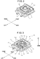
- FIG. 1 is an exploded perspective view illustrating an overall constitution of the push button-type switch device 100.
- Fig. 2 is a perspective view of the push button-type switch device 100 in an assembled state.
- a key top 40 is not shown.
- the up-and-down direction, front-and-back direction and right-and-left direction are defined as shown in the figures, and a constitution of each portion will be described according to these definitions.
- the push button-type switch device 100 includes a base portion 10, an actuating member 20 placed on an upper surface of the base portion 10, a cover 30 attached to the base portion 10 with the actuating member 20 provided therebetween, a key top 40 that is to be pushed downward in operation, and a pair of right and left link members 50 arranged between the base portion 10 and the key top 40.
- Fig. 3 is an enlarged perspective view of the base portion 10.
- the base portion 10 includes a bottom plate 11 of a substantially rectangular shape, a pair of right and left side plates 12 protruding upward from the right and left edges of the upper surface of the bottom plate 11 and extending in the form of a flat plate in the front-and-back direction, a pair of front and back side plates 13 protruding upward from the front and back ends of the upper surface of the bottom plate 11 and extending in the form of a flat plate in the right-and-left direction, and a pair of front and back guide portions 14 protruding upward on the upper surface of the bottom plate 11 and inside the side plates 12 and 13.
- the base portion 10 is made of an electrically non-conductive resin and integrally formed.
- the guide portions 14 are in the form of a substantially U-shape in a plan view and arranged opposite to each other in the front-and-back direction, and their outer side surfaces facing the side plates 12, 13 are formed in the form of a flat plate substantially in parallel with the side plates 12, 13.
- the guide portions 14 have inwardly cut-away portions of a rectangular shape at their right and left corners, so as to form recesses 14a at four corners of the pair of guide members 14 as a whole.
- the inner side surfaces of the guide members 14, on the other hand are formed of an arcuate shape, so as to form a cylindrical accommodation space on the insides of the pair of guide members 14.
- the bottom surfaces of the guide portions 14 extend inward, so as to form seat portions 14b.
- the inner circumferential edges of the seat portions 14b are in the form of an arcuate shape, so as to form a recess of a substantially circular shape on the insides of a pair of the seat portions 14b.
- cylindrical protrusions 14c are arranged so as to protrude upward.
- a pair of right and left arcuate shaft-receiving grooves 14d are formed from the upper end surfaces toward the lower sides of the guide portions 14.
- a pair of electrically conductive plates 15 are placed on the upper surface of the bottom plate 11.
- the plates 15 extend into the recessed portion inside the guide portions 14 in the front-and-back direction, so that one ends of the plates 15 are positioned close to each other, and electrically conductive fixed contacts 16 are formed so as to be raised upward on the upper surfaces at the ends of the plates 15.
- the plates 15 extend leftward under the front and back guide portions 14, and the other ends, which extend through the left side plate 12, are connected to connection terminals 17, respectively.
- the plates 15 are formed integrally with the base portion 10 by, for example, insert-molding.
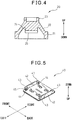
- Fig. 4 is a sectional view of the actuating member 20.
- the actuating member 20 has a symmetrical shape with the center axis in the up-and-down direction as a center, and is in the form of a substantially dome as a whole.
- the actuating member 20 includes a circular ring portion 21, a tapered portion 22 extending upward in a tapered manner from an inner circumferential edge of the circular ring portion 21, and a circular ring portion 23 erecting on the upper edge of the tapered portion 22.
- a protrusion 24 of a substantially cylindrical shape is raised from the lower part of the circular ring portion 23, and an electrically conductive movable contact 25 is provided on the lower surface of the protrusion 24.
- the actuating member 20 may be an elastic element made of a rubber material.
- the movable contact 25 may be made of an electrically conductive rubber and integrally formed with the actuating member 20 by integral forming.
- the movable contact 25 may also be formed on the lower surface of the protrusion 24 by electrically conductive printing.
- the movable contact 25 together with the fixed contacts 16 serves as a switch contact portion.
- the actuating member 20 is accommodated in the accommodation space inside the guide portions 14 of the base portion 10, and the circular ring portion 21 is placed on the seat portions 14b.
- the movable contact 25 is positioned the pair of fixed contacts 16.
- the movable contact 25 Prior to exertion of pushing force on the actuating member 20, the movable contact 25 is at an upper limit position spaced apart from the fixed contacts 16, and the switch contact portion is open.
- the tapered portion 22 is subject to elastic deformation, so that the movable contact 25 lowers and comes into contact with the pair of fixed contacts 16. This allows the pair of fixed contacts 16 to short-circuit via the movable contact 25, thereby closing the switch contact portion.
- a cover 30 in the form of a thin plate as shown in Fig. 1 is arranged on the actuating member 20.
- the cover 30 is made of, for example, a resin and integrally formed by integral forming.
- the cover 30 has an outer shape of a substantially rectangular and has, at its corners, notches 30a which correspond to the recesses 14a of the guide portions 14 ( Fig. 3 ).
- the outer shape of the cover 30 conforms with the outer shape of the pair of guide portions 14.
- a circular through hole 31 is formed in such a size smaller than an outer diameter of the circular ring portion 21 of the actuating member 20 ( Fig. 4 ) that it does not interfere with the tapered portion 22, which is elastically deformable.
- the cover 30 further has circular through holes 32 corresponding to the protrusions 14c of the base portion 10 ( Fig. 3 ).
- the protrusions 14c are inserted in the through holes 32.
- the cover 30 is fixed onto the upper surfaces of the guide portions 14, and the circular ring portion 21 of the actuating member 20 is held between the seat portions 14b and the cover 30.
- the cover 30 may also be fixed onto the upper surfaces of the guide portions 14 by melting the upper ends of the protrusions 14c by heat.
- Fig. 5 is a perspective view of the key top 40 obliquely seen from its lower side.
- the key top 40 as a whole is in the form of a flat plate of a substantially rectangular shape, made of resin and formed by integral forming.
- An operable portion 41 ( Fig. 1 ) which is to be pushed is provided on the upper surface (outer surface) of the key top 40, and a pair of front and back side plates 42 in the form of a flat plate extending in the right-and-left direction is provided, so as to protrude downward at the front and back end on the lower surface (inner surface) of the key top 40.
- the key top 40 has a length in the front-and-back direction substantially equal to a length in the front-and-back direction of the base portion 10, and has a length in the right-and-left direction substantially equal to a length in the right-and-left direction of the base portion 10.
- the pair of side plates 42 are positioned outside the pair of side plates 13 of the base portion 10 in the front-and-back direction.
- the right and left ends of the side plates 42 are thickened inwardly in the front-and-back direction, and guide grooves 44 are formed on the right and left outer side surfaces of the thickened part, so as to form shaft support portions 43 at the right and left ends of the side plates 42.
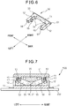
- Fig. 6 is a perspective view illustrating the constitution of the link member 50. Shown here is the constitution of the link member 50 on the right side of Fig. 1 .
- the right and left link members 50 have the same constitution and thus, if turned by 180 degrees on a horizontal plane, then the right link member 50 becomes the left link member 50.
- the link member 50 is made of a resin and formed by integral forming, and has, as shown in Fig. 6 , a body portion 51 extending in the front-and-back direction and a pair of front and back arm portions 52 extending leftward from the front and back ends of the body portion 51, forming a substantially U-shape as a whole.
- a substantially cylindrical guide shaft 53 integrally extends along the body portion 51, and both ends of the guide shaft 53 protrude outward in the front-and-back direction beyond the front and back end surfaces of the arm portions 52.
- the arm portions 52 have a substantially rectangular shape in cross section, its inner side surfaces at proximal ends (right ends) having a stepped shape, i.e., forming a step 54 protruding inward in the front-and-back direction, respectively.
- substantially cylindrical shaft portions 55 are provided so as to coaxially protrude in the front-and-back direction.
- a concave portion 56 is formed in the left end surface of the front arm portion 52 and a convex portion 57 is formed on the left end surface of the back arm portion 52.
- the concave portion 56 of one link member 50 meshes with the convex portion 57 of the other link member 50, while the convex portion 57 of one link member 50 meshes with the concave portion 56 of the other link member 50.
- a V-shaped gear link of a V-shape in side view is provided, as shown in Fig. 1 .
- the shaft portions 55 of the link members 50 are fitted to the shaft-receiving grooves 14d of the base portion 10 ( Fig. 3 ) from the upper side.
- the link members 50 are arranged in spaces between the guide portions 14 and the side plates 12, 13, respectively, as shown in Fig. 2 . Namely, the link members 50 are rotatably supported by the base portion 10 with the shaft portions 55 as fulcrums without interfering with the guide portions 14 or the side plates 12, 13.
- Fig. 7 is a sectional view of a major portion of the push button-type switch device 100, illustrating an initial state thereof before the key top 40 is pushed.
- the switch device 100 is mounted, for example, on a printed board 200.
- the printed board 200 has an electric circuit of an electrically conductive wiring pattern formed on an insulating plate.
- the base portion 10 is placed on the printed board 200, and connection terminals 17 are connected to the electric circuit on the printed board 200 by soldering or the like.
- the pair of link members 50 mesh with each other, and the shaft portions 55 of the link members 50 are rotatably supported by the shaft-receiving grooves 14d of the base portion 10. Further, the guide shafts 53 of the link members 50 are inserted in the guide grooves 44 on the inner side of the key top 40, the guide shafts 53 of the link members 50 being supported by the shaft support portions 43 of the key top 40 so as to slide along the guide grooves 44.
- the actuating member 20 is subject to elastic deformation by being pushed and flattened out, whereby the link members 50 pivot together in the opposite directions.
- the guide shafts 53 then slide in the guide grooves 44 in the right-and-left direction, and the key top 40 undergoes a downward translation movement, while maintaining the operable portion 41 in a predetermined substantially horizontal orientation.
- the movable contact 25 comes into contact with the fixed contacts 16 to close the switch contact portion.
- the key top 40 When the pushing force acting upon the key top 40 is released, with the aide of sliding movement of the link members 50, the key top 40 is moved upward by elastic force of the actuating member 20, while maintaining the horizontal orientation, until it reaches its upper limit position in the key stroke.
- the upper limit position in the key stroke is defined as the guide shafts 53 of the link members 50 are stopped by the inner walls of the shaft support portions 43 of the key top 40 in the right-and-left direction.
- the comparative example described above has the following operations and effects.
- the movable contact 25 is provided on the inside of the actuating member 20 by integral forming, the constitution of the movable contact 25 is not limited thereto. As shown in Figs. 8A and 8B , for example, the movable contact 25 may also be provided on a leaf spring 26 made of an electrically conductive metal.
- Fig. 8A is a plan view of the leaf spring 26, Fig. 8B is a side view of the same.
- the leaf spring 26 includes a flat plate portion 26a of a substantially C-shape, a leaf spring portion 26b extending upward from the inner circumferential edge of the flat plate portion 26a and toward the center of the leaf spring 26, and a contact portion 26c extending widely in the front-and-back direction at an end of the leaf spring portion 26b.
- the movable contact 25 is provided on the lower surface of the contact portion 26c.
- the flat plate portion 26a is formed of substantially the same shape as the seat portions 14b of the base portion 10 ( Fig. 3 ), and is held between the seat portions 14b and the circular ring portion 21 of the actuating member 20 with the flat plate portion 26a being insulated from the fixed contacts 16. In this manner, the movable contact 25 is positioned over the fixed contacts 16.
- the contact portion 26c is pushed via the protrusion 24 ( Fig. 4 ) inside the actuating member 20 as a result of the key top 40 being pushed, the leaf spring portion 26c is subject to elastic deformation, bringing the movable contact 25 into contact with the fixed contacts 16.
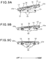
- Figs. 9A, 9B and 9C is a sectional view of a major portion of the push button-type switch device 100 illustrating an example of the attaching step of the key top 40.
- side walls 40a protrude downward on the outer sides in the right-and-left direction of the guide grooves 44 of the key top 40.
- the pair of front and back guide shafts 53 of the left side are inserted into the guide grooves 44 of the left side, while the key top 40 being tilted.
- the key top 40 is pushed down against the actuating member 20 and turned downward the right side of the key top 40 until it reaches the lower limit position.
- the key top 40 is then shifted rightward, and the pair of front and back guide shafts 53 are inserted into the guide grooves 44 of the right side.
- pushing the key top 40 is terminated, and then, as shown in Fig. 9C , the key top 40 is urged up by elastic force of the actuating member 20, whereby the attaching step is completed.
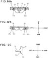
- the guide shafts 53 of the link members 50 may be constituted as shown in Figs. 10A, 10B and 10C , for example.
- Figs. 10A and 10B is a sectional view illustrating a major portion of the switch device 100 before and after the key top 40 is pushed in operation, respectively.
- Fig. 10C is a view illustrating a right and back end of the guide shaft 53 in the state shown in Fig. 10B , seen from the upper side.
- the guide shafts 53 of the pair of right and left link members 50 have cut away portions so as to have a circular cross section linearly cut away. That is, flat surfaces 53a extending in the front-and-back direction are formed in the guide shafts 53, so that the guide shafts 53 have a substantially D-shape in cross section in side view.
- the flat surfaces 53a of the right and left guide shafts 53 are oriented obliquely in a substantially symmetrical manner.
- the flat surfaces 53a of the right and left guide shafts 53 are oriented in the up-and-down direction, in parallel and opposite to each other. This allows the flat surfaces 53a of the guide shafts 53 to be guided into the guide grooves 44 along the right and left outer side end surfaces 43a of the shaft support portions 43 when the key top 40 is attached. Therefore, the key top 40 needs be shifted in a shorter distance in the right-and-left direction, facilitating the attaching step.
- a decreased amount of force acts on the guide shafts 53, thereby preventing the shaft support portions 43 and the guide shafts 53 from being deformed or broken.
- the flat surfaces 53a of the guide shafts 53 can shift from the state shown in Fig. 10A to the state shown in Fig. 10B without making contact with the shaft support portions 43, whereby smooth sliding of the guide shafts 53 is achieved.
- Figs. 11A, 11B and 11C is a view illustrating a modified example of Fig. 10A, 10B and 10C .
- Figs. 11A and 11B is a sectional view illustrating a major portion of the key top 40 before and after it is pushed in operation, respectively.
- Fig. 11C is a view illustrating a right and back end part of the guide shaft 53 in the state shown in Fig. 11B , seen from the upper side.
- slits 53b are formed inwardly in the front-and-back direction on the front and back end surfaces of the guide shafts 53 of the pair of link members 50.
- the slits 53b are formed in the central portions of the front and back end surfaces of guide shafts 53 so as to extend through in the up-and-down direction in a state shown in Fig. 11B . This allows the guide shafts 53 to be easily elastically deformed in the right-and-left direction with the aide of the slits 53b, thereby facilitating insertion of the guide shaft 53 into the guide grooves 44.
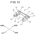
- FIG. 12 is a perspective view of the link member 50 showing an example thereof.
- notches 53c are formed on inner portions of the guide shaft 53 in the front-and-back direction, the notches 53c extending inwardly from the outer end surfaces in the right-and-left direction.
- the notches 53c extend through the link member 50 in the up-and-down direction. This results in applying compressive force onto the front and back end surfaces of the guide shaft 53 in the front-and-back direction, and therefore, the guide shaft 53 can be easily elastically deformed inwardly in the front-and-back direction, thereby facilitating insertion of the guide shaft 53 into the guide groove 44.
- the shaft support portions 43 of the key top 40 may also be constituted in an elastically deformable shape.
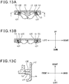
- Figs. 13A, 13B and 13C is a diagram of an example thereof.
- Figs. 13A and 13B is a sectional view of a major portion of the key top 40 before and after it is pushed in operation, respectively.
- Fig. 13C is a sectional view along line C-C in Fig. 13A .
- notches 430 are formed in the upper end portions of the shaft support portions 43, so as to extend in the front-and-back direction. As shown in Figs.
- the shaft support portions 43 is of a substantially L-shape in cross section under the notches 430, so as to form L-shaped portions 431.
- the L-shaped portions 431 are elastically deformably supported at its one end by the bottom surface on the inside of the key top 40 in the front-and-back direction.
- the L-shaped portions 431 can be elastically deformed, and the key top 40 can be easily attached to, and detached from the link members 50 without causing the guide shafts 53 or the shaft support portions 43 to be plastically deformed or broken.
- the key top 40 in the state shown in Fig. 13A is pulled up, spaces in the notches 430 (height in the up-and-down direction) are expanded by the pulling force, and the guide shafts 53 can be slid in and through the notches 430 inwardly in the right-and-left direction. This allows the key top 40 to be removed without damaging the guide shaft 53 or the shaft support portions 43 even if a user attempt to forcibly pull out the key top 40.
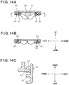
- Figs. 14A, 14B and 14C is a view illustrating an example thereof.
- Figs. 14A and 14B is a sectional view of a major portion of the key top 40 before and after it is pushed in operation, respectively.
- Fig. 14C is a sectional view along line C-C in Fig. 14A .
- ribs 45 are provided to protrude on the right and left outer sides of the shaft support portions 43.
- the guide shafts 53 are guided by the shaft support portions 43 and ribs 45 and inserted into the guide grooves 44, the ribs 45 serving to prevent the shaft portions 53 from being slipped off.
- This allows, as shown in Fig. 14B , a length of undercut to be shortened by a predetermined length ⁇ L as compared to a length shown in Fig. 10C (by dotted line).
- the key top 40 can be easily attached to and detached from the link members 50 without causing the guide shafts 53 or the shaft support portions 43 to be plastically deformed or broken.
- the constitution shown in Fig. 13 may be combined with the constitution shown in Fig. 14 .
- the link members 50 do not have to be constituted as shown in Figs. 10 to 12 . Therefore, there is no need to newly fabricate a metal mold for molding the link members 50, preventing a production cost of the link members 50 being increased. Yet constitutions of the link members 50 shown in Figs. 10 to 12 may also be applied to the embodiments shown in Figs. 13 and 14 .
- the pair of link members forming the V-shaped gear link can also be applied to a push button-type switch device having a membrane switch.
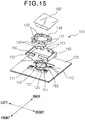
- Fig. 15 is an exploded perspective view of a push button-type switch device 101 to which the pair of link members are applied, and
- Fig. 16 is a perspective view illustrating a state where the push button-type switch device has been assembled. The key top is not shown in Fig. 16 .
- the push button-type switch device 101 includes a membrane switch 120 mounted on a support panel 110, a housing 130 erecting on the support panel 110, an actuating member 140 arranged on the membrane switch 120 inside the housing 130, a pair of link members 150 rotatably supported by the housing 130, and a key top 160 which is to be pushed in operation.
- the link members 150 and the key top 160 are the same as those of the link members 50 and the key top 40 described above.
- the link members 150 is of a substantially U-shape, have shaft portions 151 formed coaxially on inner side surfaces of its arm portions so as to protrude inward in the front-and-back direction and have guide shafts 152 formed coaxially on outer side surfaces of the arm portions so as to protrude outward in the front-and-back direction.
- the support panel 110 is a plate member made of a resin, metal or the like and has a plurality (four in the drawing) of through holes 111 therein for mounting the housing 130.
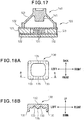
- Fig. 17 is a sectional view along line XVII-XVII in Fig. 16 .
- the membrane switch 120 includes a pair of contacts 121 provided opposite to each other on an upper and lower sides, a pair of sheet substrates 122 carrying the pair of contacts 121, respectively, and a spacer 123 arranged between the pair of sheet substrates 122 so as to keep the two contacts 121 open with the sheet substrates spaced apart from each other by a predetermined distance.
- the sheet substrate 122 has through holes in the circumference of the through holes 111, the right and left through holes in communication with each other in the sheet substrate 122, so as form a pair of front and back elongated holes 124.
- An actuating member 140 similarly to the actuating member 20 described above, is substantially in the form of a dome and is arranged on the membrane switch 120 between the pair of front and back elongated holes 124. As shown in Fig. 17 , a protrusion 141 is raised facing downward inside the actuating member 140 and is positioned over the contacts 121. When the key top 160 is pushed, a tapered portion 142 of the actuating member 140 is subject to elastic deformation and the protrusion 141 lowers. Lowering movement of the protrusion 141 results in predetermined downward pushing force acting on the contact 121, thereby closing the upper and lower contacts 121. When the pushing force acting on the key top 160 is released, the protrusion 141 moves up due to elastic force of the actuating member 140 and the contacts 121 are opened.
- the housing 130 in the form of a substantially rectangular frame is made by resin molding and has legs 131 projecting downward at the four corners thereof. Between the right and left legs 131 of the housing 130, a pair of front and back side walls 132 extend in the right-and-left direction, respectively. The legs 131 protrude downward beyond the side walls 132. Lower end surfaces of the side walls 132 come into contact with the upper surface of the support panel 110 through the elongated holes 124, and the housing 130 is supported on the support panel 110. The legs 131 extend through the through holes 111 and their distal ends are fixed onto the support panel 110 by thermal caulking on the opposite side of the support panel 110.
- a pair of arcuate shaft-receiving grooves 133 are formed upward from its lower end surface, the shaft-receiving grooves 133 being spaced apart in the right-and-left direction.
- the housing 130 is inserted into a space between the actuating member 140 and the link members 150 from the upper side, and is fixed to the support panel 110.
- the shaft portions 151 of the link members 150 fit in the shaft-receiving grooves 133, and the link members 150 are rotatably supported by the housing 130.
- the legs 131 of the housing 130 are fixed to the support panel 110 by thermal caulking. During the thermal caulking, this results in having a high temperature on the overall support panel. As a result, contact regions (lower ends of side walls 132) where the housing 130 comes into contact with the support panel 110 are exposed to the high temperature, possibly resulting in thermal deformation of the side walls 132 of the housing 130, adversely affecting in assembling the link members 150 or in a smooth operation thereof.
- the housing 130 may be constituted, for example, as shown in Figs. 18A and 18B .
- Fig. 18A is a plan view of the housing 130
- Fig. 18B is a sectional view along line B-B in Fig. 18A
- the housing 130 has protrusions 135 formed at central portions on the bottom surfaces of the front and back side walls 132 of the housing 130. In this manner, when the housing 130 is attached, the protrusions 135 come into contact with the upper surface of the support panel 110, and a gap is formed in the areas other than the contacting portions between the lower end surfaces of the side walls 132 and the upper surface of the support panel 110. This decreases the contact surface area between the housing 130 and the support panel 110, and an amount of heat transfer from the support panel 110 to the housing 130 will decrease during the thermal caulking of the legs 131.
- Fig. 19A is a plan view of the housing 130 showing a modified example of the housing 130 shown in Figs. 18A and 18B .
- Fig. 19B is a sectional view along line B-B in Fig. 19A.
- Fig. 19B also shows the support panel 110.
- protrusions 136 of a substantially conical shape are formed at central portions on the bottom surfaces of the front and back side walls 132 of the housing 130, and through holes 112 are formed in the support panel 110, corresponding to the protrusions 136.
- the through holes 112 have a diameter smaller than that of the proximal ends of the protruded portions 136.
- peripheral surfaces of the protrusions 136 come into contact with an upper open edges of the through holes 112, and a gap is formed in the areas other than the contacting portions between the lower end surfaces of the side walls 132 and the upper surface of the support panel 110. This decreases the contact surface area decreases between the housing 130 and the support panel 110, and an amount of heat transfer from the support panel 110 to the housing 130 will decrease.
- the housing 130 can be positioned relative to the support panel 110, thereby preventing the housing 130 from being deviated in position during the thermal caulking.
- Figs. 18 and 19 protrusions 135, 136 are provided on the bottom surface of the housing 130 to reduce the amount of heat transfer from the support panel 110 to the housing 130.
- a heat-insulating film interposed between the housing 130 and the support panel 110 so as to lower the amount of heat transfer from the support panel 110 to the housing 130.
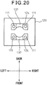
- Fig. 20 is a plan view of a membrane switch 120 showing an example thereof.
- heat-insulating films 137 are mounted on the upper surface of the support panel 110 where the side walls 132 of the housing 130 are to be placed in such a manner that the heat-insulating films 137 partly close the through holes 124 of the membrane switch 120.
- the same membrane films forming the surface of the membrane switch 120 can be used as the heat-insulating films 137.
- the membrane films are made of a PET sheet with excellent heat resistance (e.g., with upper temperature limit of 150°C), and therefore posing no risk to melting the membrane films or the like even if they are exposed to heat for thermal caulking.
- the base portion 10 provided with the pair of fixed contacts 16 is mounted on the printed board 200, but may also be mounted on other member.
- the gear link of a V-shape in side view is constituted by meshing the concave portions 56 and the convex portions 57 of the pair of link members 50 with each other.
- a shape of the link members 50 and an engaging manner of the pair of link members 50 are not limited thereto. Any constitution may be employed as a limiting part for limiting the direction in which the key top 40 moves, provided that the key top 40 as the operable member can be moved in an unchanged predetermined orientation with the aid of the pair of link members 50 engaged with each other.
- the pair of link members 50 may be turned upside down, so that the shaft portions 55 are rotatably supported by the inner side of the key top 40 and that the guide shafts 53 is slidably supported by the base portion 10.
- the operable portion 41 of the key top 40 does not necessarily have a horizontal surface.
- the operable portion 41 may be arranged obliquely, and the key top 40 may be moved perpendicularly (in the up-and-down direction) to the base portion 10 while maintaining the oblique surface.
- the pair of link members 50 are accommodated in the spaces (accommodation portions) between the side plates 12, 13 and the guide portions 14 of the base portion 10. However, when the link members 50 are turned upside down, the accommodating portions may be provided on the inner side of the key top 40.
- the guide shafts 53 are formed of a substantially D-shape in cross section, or slits 53b are formed in the guide shafts 53, or notches 53c are formed in the guide shafts 53 substantially perpendicularly (in the right-and-left direction) to the direction in which the guide shafts 53 protrude.
- the guide shafts 53 which serve as sliding shafts for facilitating the attachment of the key top 40 are not limited to the above-mentioned constitutions.
- the flat surfaces 53a of the guide shafts 53 are, as shown in Fig. 10 , guided in the guide grooves 44 along the end surfaces of the shaft support portions 43, the constitution for guiding is not limited thereto. In the above embodiment ( Fig.
- notches 430 are formed in the shaft support portions 43 to form L-shaped portions 431.
- hanging portions of any shape other than the L-shape may be possible, provided that they hang down and are spaced apart from the bottom surface of the key top 40.
- ribs 45 are provided on the right and left outer sides of the shaft support portions 43.
- the ribs 45 may be constituted in any form, provided that they hang down from the bottom surface of the key top 40 and face the shaft support portions 43, thereby, together with the shaft support portions 43, guiding the guide shafts 53.
- the membrane switch 120 including the pair of contacts 121 facing each other on the upper and lower sides is arranged on the support panel 110 that serves as a support plate. It may, however, also be possible to employ any other contact portion actuated by pushing the key top 160.
- the housing 130 is not limited to the above constitution, provided that it fixedly erects on the support panel 110 so as to surround the contact portion.
- the heat transfer reducing means is not limited to the above constitution, provided that it is constituted so as to reduce an amount of heat transfer to the housing 130 at the contact regions between the end surfaces of the housing 130 and the upper surface of the support panel 110. Although through holes 112 are formed in the support panel 110 as shown in Fig.
- the fitting portions may be constituted simply as concave portions.
- the heat-insulating films 137 may also be applied to the end surfaces of the housing 130.
- the present invention is not limited to any push button-type switch device according to the above embodiments, and is defined in the appended claims.
Description
- This invention relates to a push button-type switch device used for a variety of electronic equipment.
- There has heretofore been known a push button-type switch device having a key top supported via a skirt portion which is made of an elastic material (see, for example,
JP-A-9-120741 JP-A-9-120741 - In the device described in
JP-A-9-120741 -
EP-A-2040275 describes a key switch including a base section, a key top, a pair of link members and a switching mechanism. Each link member is provided, at one end region thereof, with a toothed portion meshable with a toothed portion of another link member in a gearing manner and a pivot axle pivotably joined to the base section, and at another end region, with a slide portion slidably engaged with the key top. The base section includes a support plate and a frame member, the frame member being fixedly attached to the uppoer surface of the support plate. The frame member is provided with a bearing portion pivotably receiving and supporting the pivot axle of each link member. The first end region of each link member is disposed on a lateral side of the frame member and closely to the upper surface of the support plate. - A push button-type switch device according to a first aspect of the present invention comprises:
- a support plate;
- an operable member to be pushed in operation;
- a contact portion arranged on said support plate and actuated upon said operable member being pushed;
- an actuating member interposed between said support plate and said operable member, and elastically deformable upon said operable member being pushed, said actuating member providing a nonlinear counteracting force to said operable member depending upon elastic deformation of said actuating member;
- a housing fixedly erected on said support plate and surrounding said contact portion; and
- a pair of link members rotatably supported by said housing, and actuated together with said operable member upon said operable member being pushed, said pair of link members limiting a direction in which said operable member moves and making said operable member move in a direction perpendicular to said support plate,
- and is characterized in that heat transfer reducing part formed from protrusions protruding from a lower end surface of said housing toward an upper surface of said support plate is provided such that a gap is formed between the lower end surfaces of said housing and the upper surface of said support plate whereby said heat transfer reducing part lowering an amount of heat transfer from said support plate to said housing.
- In accordance with a second aspect of the present invention, we provide a push button-type switch device comprising:
- a support plate;
- an operable member to be pushed in operation;
- a contact portion arranged on said support plate and actuated upon said operable member being pushed;
- an actuating member interposed between said support plate and said operable member, and elastically deformable upon said operable member being pushed, said actuating member providing a nonlinear counteracting force to said operable member depending upon elastic deformation of said actuating member;
- a housing fixedly erected on said support plate and surrounding said contact portion; and
- a pair of link members rotatably supported by said housing, and actuated together with said operable member upon said operable member being pushed, said pair of link members limiting a direction in which said operable member (moves and making said operable member move in a direction perpendicular to said support plate,
- characterized in that said support plate is provided with through holes, through which said housing is mounted to said support plate, and in that
- said push button-type switch device further comprises:
- a membrane switch provided with through holes in the circumference of said through holes of said support plate; and
- a heat transfer reducing part formed from heat-insulating films interposed between a lower end surface of said housing and an upper surface of said support plate such that the heat-insulating films partly close said through holes of said membrane switch and that the heat transfer reducing part lowers an amount of heat transfer from said support plate to said housing.
- According to the present invention, the direction in which the operable member moves upon being pushed is limited so as to allow the operable member to move in a fixed orientation. Therefore, the actuating member between the base portion and the operable member can be elastically deformed uniformly in the circumferential direction to produce a good click when being pushed.
- These and other objects, features and advantages of the present invention will be more apparent in light of the detailed description of exemplary embodiments and comparative examples thereof as illustrated by the drawings.
-
-
Fig. 1 is an exploded perspective view of a push button-type switch device according to a comparative example; -
Fig. 2 is a perspective view of the push button-type switch device ofFig. 1 in an assembled state; -
Fig. 3 is an enlarged view of a base portion ofFig. 1 ; -
Fig. 4 is a sectional view of an actuating member ofFig. 1 ; -
Fig. 5 is a perspective view of a key top ofFig. 1 obliquely seen from its lower side; -
Fig. 6 is a perspective view illustrating the constitution of a link member ofFig. 1 ; -
Fig. 7 is a sectional view of a major portion of the push button-type switch device according to the comparative example in an assembled state; -
Figs. 8A and 8B is a view illustrating a modified example of a movable contact; -
Figs. 9A, 9B and 9C is a sectional view of a major portion of the push button-type switch device illustrating an example of the steps of attaching the key top; -
Figs. 10A, 10B and 10C is a view illustrating a first modified example of the link members; -
Figs. 11A, 11B and 11C is a view illustrating a second modified example of the link members; -
Fig. 12 is a view illustrating a third modified example of the link member; -
Figs. 13A, 13B and 13C is a view illustrating a first modified example of the key top; -
Figs. 14A, 14B and 14C is a view illustrating a second modified example of the key top; -
Fig. 15 is an exploded perspective view of the push button-type switch device having a membrane switch according to one embodiment of the invention; -
Fig. 16 is a perspective view illustrating the push button-type switch device ofFig. 15 in an assembled state; -
Fig. 17 is a sectional view along line XVII-XVII ofFig. 16 ; -
Figs. 18A and 18B is a view illustrating a modified example of a housing ofFig. 15 ; -
Figs. 19A and 19B is a view illustrating another modified example of the housing ofFig. 15 ; and -
Fig. 20 is a view illustrating a modified example of the membrane switch ofFig. 15 . - A push button-type switch device according to a comparative example will now be described.
Fig. 1 is an exploded perspective view illustrating an overall constitution of the push button-type switch device 100.Fig. 2 is a perspective view of the push button-type switch device 100 in an assembled state. InFig. 2 , a key top 40 is not shown. In the following description for convenience, the up-and-down direction, front-and-back direction and right-and-left direction are defined as shown in the figures, and a constitution of each portion will be described according to these definitions. - The push button-
type switch device 100 includes abase portion 10, an actuatingmember 20 placed on an upper surface of thebase portion 10, acover 30 attached to thebase portion 10 with the actuatingmember 20 provided therebetween, a key top 40 that is to be pushed downward in operation, and a pair of right and leftlink members 50 arranged between thebase portion 10 and thekey top 40. -
Fig. 3 is an enlarged perspective view of thebase portion 10. Thebase portion 10 includes abottom plate 11 of a substantially rectangular shape, a pair of right and leftside plates 12 protruding upward from the right and left edges of the upper surface of thebottom plate 11 and extending in the form of a flat plate in the front-and-back direction, a pair of front andback side plates 13 protruding upward from the front and back ends of the upper surface of thebottom plate 11 and extending in the form of a flat plate in the right-and-left direction, and a pair of front and back guideportions 14 protruding upward on the upper surface of thebottom plate 11 and inside theside plates base portion 10 is made of an electrically non-conductive resin and integrally formed. - The
guide portions 14 are in the form of a substantially U-shape in a plan view and arranged opposite to each other in the front-and-back direction, and their outer side surfaces facing theside plates side plates guide portions 14 have inwardly cut-away portions of a rectangular shape at their right and left corners, so as to formrecesses 14a at four corners of the pair ofguide members 14 as a whole. The inner side surfaces of theguide members 14, on the other hand, are formed of an arcuate shape, so as to form a cylindrical accommodation space on the insides of the pair ofguide members 14. The bottom surfaces of theguide portions 14 extend inward, so as to formseat portions 14b. The inner circumferential edges of theseat portions 14b are in the form of an arcuate shape, so as to form a recess of a substantially circular shape on the insides of a pair of theseat portions 14b. - On the upper surfaces at the right and left ends of the
guide portions 14,cylindrical protrusions 14c are arranged so as to protrude upward. At each of the front and back ends of theguide portions 14, a pair of right and left arcuate shaft-receiving grooves 14d are formed from the upper end surfaces toward the lower sides of theguide portions 14. - A pair of electrically
conductive plates 15 are placed on the upper surface of thebottom plate 11. Theplates 15 extend into the recessed portion inside theguide portions 14 in the front-and-back direction, so that one ends of theplates 15 are positioned close to each other, and electrically conductivefixed contacts 16 are formed so as to be raised upward on the upper surfaces at the ends of theplates 15. Theplates 15 extend leftward under the front and back guideportions 14, and the other ends, which extend through theleft side plate 12, are connected toconnection terminals 17, respectively. Theplates 15 are formed integrally with thebase portion 10 by, for example, insert-molding. -
Fig. 4 is a sectional view of the actuatingmember 20. The actuatingmember 20 has a symmetrical shape with the center axis in the up-and-down direction as a center, and is in the form of a substantially dome as a whole. Namely, the actuatingmember 20 includes acircular ring portion 21, a taperedportion 22 extending upward in a tapered manner from an inner circumferential edge of thecircular ring portion 21, and acircular ring portion 23 erecting on the upper edge of the taperedportion 22. Aprotrusion 24 of a substantially cylindrical shape is raised from the lower part of thecircular ring portion 23, and an electrically conductivemovable contact 25 is provided on the lower surface of theprotrusion 24. The actuatingmember 20 may be an elastic element made of a rubber material. Themovable contact 25 may be made of an electrically conductive rubber and integrally formed with the actuatingmember 20 by integral forming. Themovable contact 25 may also be formed on the lower surface of theprotrusion 24 by electrically conductive printing. Themovable contact 25 together with the fixedcontacts 16 serves as a switch contact portion. - The actuating
member 20 is accommodated in the accommodation space inside theguide portions 14 of thebase portion 10, and thecircular ring portion 21 is placed on theseat portions 14b. In a state where the actuatingmember 20 has been placed on thebase portion 10, themovable contact 25 is positioned the pair of fixedcontacts 16. Prior to exertion of pushing force on the actuatingmember 20, themovable contact 25 is at an upper limit position spaced apart from the fixedcontacts 16, and the switch contact portion is open. Upon pushing force being exerted downward on the actuatingmember 20, the taperedportion 22 is subject to elastic deformation, so that themovable contact 25 lowers and comes into contact with the pair of fixedcontacts 16. This allows the pair of fixedcontacts 16 to short-circuit via themovable contact 25, thereby closing the switch contact portion. - A
cover 30 in the form of a thin plate as shown inFig. 1 is arranged on the actuatingmember 20. Thecover 30 is made of, for example, a resin and integrally formed by integral forming. Thecover 30 has an outer shape of a substantially rectangular and has, at its corners,notches 30a which correspond to therecesses 14a of the guide portions 14 (Fig. 3 ). The outer shape of thecover 30 conforms with the outer shape of the pair ofguide portions 14. At the central part of thecover 30, a circular throughhole 31 is formed in such a size smaller than an outer diameter of thecircular ring portion 21 of the actuating member 20 (Fig. 4 ) that it does not interfere with the taperedportion 22, which is elastically deformable. - The
cover 30 further has circular throughholes 32 corresponding to theprotrusions 14c of the base portion 10 (Fig. 3 ). In the assembled state as shown inFig. 2 , theprotrusions 14c are inserted in the through holes 32. In this state, the upper ends of theprotrusions 14c are crushed by means of a hammer or the like, thecover 30 is fixed onto the upper surfaces of theguide portions 14, and thecircular ring portion 21 of the actuatingmember 20 is held between theseat portions 14b and thecover 30. Thecover 30 may also be fixed onto the upper surfaces of theguide portions 14 by melting the upper ends of theprotrusions 14c by heat. -
Fig. 5 is a perspective view of the key top 40 obliquely seen from its lower side. The key top 40 as a whole is in the form of a flat plate of a substantially rectangular shape, made of resin and formed by integral forming. An operable portion 41 (Fig. 1 ) which is to be pushed is provided on the upper surface (outer surface) of the key top 40, and a pair of front andback side plates 42 in the form of a flat plate extending in the right-and-left direction is provided, so as to protrude downward at the front and back end on the lower surface (inner surface) of thekey top 40. - The key top 40 has a length in the front-and-back direction substantially equal to a length in the front-and-back direction of the
base portion 10, and has a length in the right-and-left direction substantially equal to a length in the right-and-left direction of thebase portion 10. In the state where theswitch device 100 has been assembled, the pair ofside plates 42 are positioned outside the pair ofside plates 13 of thebase portion 10 in the front-and-back direction. The right and left ends of theside plates 42 are thickened inwardly in the front-and-back direction, and guidegrooves 44 are formed on the right and left outer side surfaces of the thickened part, so as to formshaft support portions 43 at the right and left ends of theside plates 42. -
Fig. 6 is a perspective view illustrating the constitution of thelink member 50. Shown here is the constitution of thelink member 50 on the right side ofFig. 1 . The right and leftlink members 50, however, have the same constitution and thus, if turned by 180 degrees on a horizontal plane, then theright link member 50 becomes theleft link member 50. - The
link member 50 is made of a resin and formed by integral forming, and has, as shown inFig. 6 , abody portion 51 extending in the front-and-back direction and a pair of front andback arm portions 52 extending leftward from the front and back ends of thebody portion 51, forming a substantially U-shape as a whole. On a rear surface (right end surface) of thebody portion 51, a substantiallycylindrical guide shaft 53 integrally extends along thebody portion 51, and both ends of theguide shaft 53 protrude outward in the front-and-back direction beyond the front and back end surfaces of thearm portions 52. - The
arm portions 52 have a substantially rectangular shape in cross section, its inner side surfaces at proximal ends (right ends) having a stepped shape, i.e., forming astep 54 protruding inward in the front-and-back direction, respectively. On the inner side surfaces at distal ends of thearm portions 52, substantiallycylindrical shaft portions 55 are provided so as to coaxially protrude in the front-and-back direction. Aconcave portion 56 is formed in the left end surface of thefront arm portion 52 and aconvex portion 57 is formed on the left end surface of theback arm portion 52. - The
concave portion 56 of onelink member 50 meshes with theconvex portion 57 of theother link member 50, while theconvex portion 57 of onelink member 50 meshes with theconcave portion 56 of theother link member 50. In this way, a V-shaped gear link of a V-shape in side view is provided, as shown inFig. 1 . Theshaft portions 55 of thelink members 50 are fitted to the shaft-receiving grooves 14d of the base portion 10 (Fig. 3 ) from the upper side. Here, thelink members 50 are arranged in spaces between theguide portions 14 and theside plates Fig. 2 . Namely, thelink members 50 are rotatably supported by thebase portion 10 with theshaft portions 55 as fulcrums without interfering with theguide portions 14 or theside plates -
Fig. 7 is a sectional view of a major portion of the push button-type switch device 100, illustrating an initial state thereof before the key top 40 is pushed. Theswitch device 100 is mounted, for example, on a printedboard 200. The printedboard 200 has an electric circuit of an electrically conductive wiring pattern formed on an insulating plate. Thebase portion 10 is placed on the printedboard 200, andconnection terminals 17 are connected to the electric circuit on the printedboard 200 by soldering or the like. - In the state where the
switch device 100 has been assembled, the pair oflink members 50 mesh with each other, and theshaft portions 55 of thelink members 50 are rotatably supported by the shaft-receiving grooves 14d of thebase portion 10. Further, theguide shafts 53 of thelink members 50 are inserted in theguide grooves 44 on the inner side of the key top 40, theguide shafts 53 of thelink members 50 being supported by theshaft support portions 43 of the key top 40 so as to slide along theguide grooves 44. - With such a constitution when a pushing force acts on the
operable portion 41 of the key top 40, the actuatingmember 20 is subject to elastic deformation by being pushed and flattened out, whereby thelink members 50 pivot together in the opposite directions. Theguide shafts 53 then slide in theguide grooves 44 in the right-and-left direction, and the key top 40 undergoes a downward translation movement, while maintaining theoperable portion 41 in a predetermined substantially horizontal orientation. As the key top 40 moves to its lower limit position in the key stroke, themovable contact 25 comes into contact with the fixedcontacts 16 to close the switch contact portion. - When the pushing force acting upon the key top 40 is released, with the aide of sliding movement of the
link members 50, the key top 40 is moved upward by elastic force of the actuatingmember 20, while maintaining the horizontal orientation, until it reaches its upper limit position in the key stroke. The upper limit position in the key stroke is defined as theguide shafts 53 of thelink members 50 are stopped by the inner walls of theshaft support portions 43 of the key top 40 in the right-and-left direction. - The comparative example described above has the following operations and effects.
- (1) The
shaft portions 55 at the proximal end of the pair oflink members 50 which mesh with each other are rotatably supported by the shaft-receiving portions 14d of thebase portion 10, and theguide shafts 53 at the distal end of the pair oflink members 50 are supported by theshaft support portions 43 on the inner side of the key top 40 so as to slide in the right-and-left direction. This allows the key top 40 to maintain its horizontal orientation without tilting even if an end of theoperable portion 41 of the key top 40 is pushed. Therefore, the actuatingmember 20 is subject to elastic deformation uniformly in the circumferential direction, producing good click feeling, thereby improving operability of theswitch device 100, and stabilizing the opening/closing operation of the switch contact portion. - (2) When the key top 40 is pushed down, the
link members 50 are accommodated in the spaces formed between the side plats 12, 13 and theguide portions 14 of thebase portion 10. This allows thelink members 50 to pivot without interfering with thebase portion 10 or the actuatingmember 20, whereby the height of theswitch device 100 can be easily lowered. - (3) The
link members 50 are formed of a substantially U-shape and are arranged to surround the actuatingmember 20, thereby enabling theswitch device 100 to be compact in size in both the front-and-back direction and the right-and-left direction. - (4) The
movable contact 25 is provided on theprotrusion 24 inside the actuatingmember 20 by integral forming, whereby themovable contact 25 is stably attached to the actuatingmember 20. - (5) The push button-
type switch device 100 is constituted by arranging, on thebase portion 10, the actuatingmember 20, thecover 30 and the key top 40 on top of one another, whereby theswitch device 100 can be easily assembled. - Although the
movable contact 25 is provided on the inside of the actuatingmember 20 by integral forming, the constitution of themovable contact 25 is not limited thereto. As shown inFigs. 8A and 8B , for example, themovable contact 25 may also be provided on aleaf spring 26 made of an electrically conductive metal.Fig. 8A is a plan view of theleaf spring 26,Fig. 8B is a side view of the same. Theleaf spring 26 includes aflat plate portion 26a of a substantially C-shape, aleaf spring portion 26b extending upward from the inner circumferential edge of theflat plate portion 26a and toward the center of theleaf spring 26, and acontact portion 26c extending widely in the front-and-back direction at an end of theleaf spring portion 26b. Themovable contact 25 is provided on the lower surface of thecontact portion 26c. - In this case, the
flat plate portion 26a is formed of substantially the same shape as theseat portions 14b of the base portion 10 (Fig. 3 ), and is held between theseat portions 14b and thecircular ring portion 21 of the actuatingmember 20 with theflat plate portion 26a being insulated from the fixedcontacts 16. In this manner, themovable contact 25 is positioned over the fixedcontacts 16. When thecontact portion 26c is pushed via the protrusion 24 (Fig. 4 ) inside the actuatingmember 20 as a result of the key top 40 being pushed, theleaf spring portion 26c is subject to elastic deformation, bringing themovable contact 25 into contact with the fixedcontacts 16. On the other hand, when the pushing force acting upon the key top 40 is released and theprotrusion 24 of the actuatingmember 20 moves up, thecontact portion 26c moves up due to spring force of theleaf spring portion 26b, lifting themovable contact 25 away from the fixedcontacts 16. - In the state where the push button-
type switch device 100 has been assembled, the key top 40 is attached by inserting theguide shafts 53 of thelink members 50 into theguide grooves 44 of thekey top 40. The attaching step is performed, for example, as described below.Figs. 9A, 9B and 9C is a sectional view of a major portion of the push button-type switch device 100 illustrating an example of the attaching step of thekey top 40. InFigs. 9A, 9B and 9C ,side walls 40a protrude downward on the outer sides in the right-and-left direction of theguide grooves 44 of thekey top 40. - First, in this case as shown in
Fig. 9A , the pair of front andback guide shafts 53 of the left side are inserted into theguide grooves 44 of the left side, while the key top 40 being tilted. Next, as shown inFig. 9B , while theguide shafts 53 of the left side are inserted in the innermost positions of theguide grooves 44, the key top 40 is pushed down against the actuatingmember 20 and turned downward the right side of the key top 40 until it reaches the lower limit position. The key top 40 is then shifted rightward, and the pair of front andback guide shafts 53 are inserted into theguide grooves 44 of the right side. Thereafter, pushing the key top 40 is terminated, and then, as shown inFig. 9C , the key top 40 is urged up by elastic force of the actuatingmember 20, whereby the attaching step is completed. - In order to facilitate the above attaching step, the
guide shafts 53 of thelink members 50 may be constituted as shown inFigs. 10A, 10B and 10C , for example.Figs. 10A and 10B is a sectional view illustrating a major portion of theswitch device 100 before and after the key top 40 is pushed in operation, respectively.Fig. 10C is a view illustrating a right and back end of theguide shaft 53 in the state shown inFig. 10B , seen from the upper side. InFigs. 10A, 10B and 10C , theguide shafts 53 of the pair of right and leftlink members 50 have cut away portions so as to have a circular cross section linearly cut away. That is,flat surfaces 53a extending in the front-and-back direction are formed in theguide shafts 53, so that theguide shafts 53 have a substantially D-shape in cross section in side view. - In the state shown in
Fig. 10A , theflat surfaces 53a of the right and leftguide shafts 53 are oriented obliquely in a substantially symmetrical manner. In the state shown inFig. 10B , theflat surfaces 53a of the right and leftguide shafts 53 are oriented in the up-and-down direction, in parallel and opposite to each other. This allows theflat surfaces 53a of theguide shafts 53 to be guided into theguide grooves 44 along the right and left outer side end surfaces 43a of theshaft support portions 43 when the key top 40 is attached. Therefore, the key top 40 needs be shifted in a shorter distance in the right-and-left direction, facilitating the attaching step. Also, in attaching the key top 40, a decreased amount of force acts on theguide shafts 53, thereby preventing theshaft support portions 43 and theguide shafts 53 from being deformed or broken. When the key top 40 is pushed, theflat surfaces 53a of theguide shafts 53 can shift from the state shown inFig. 10A to the state shown inFig. 10B without making contact with theshaft support portions 43, whereby smooth sliding of theguide shafts 53 is achieved. -
Figs. 11A, 11B and 11C is a view illustrating a modified example ofFig. 10A, 10B and 10C .Figs. 11A and 11B is a sectional view illustrating a major portion of the key top 40 before and after it is pushed in operation, respectively.Fig. 11C is a view illustrating a right and back end part of theguide shaft 53 in the state shown inFig. 11B , seen from the upper side. InFigs. 11A, 11B and 11C , slits 53b are formed inwardly in the front-and-back direction on the front and back end surfaces of theguide shafts 53 of the pair oflink members 50. Theslits 53b are formed in the central portions of the front and back end surfaces ofguide shafts 53 so as to extend through in the up-and-down direction in a state shown inFig. 11B . This allows theguide shafts 53 to be easily elastically deformed in the right-and-left direction with the aide of theslits 53b, thereby facilitating insertion of theguide shaft 53 into theguide grooves 44. - Notches may also be formed in root portions of the
guide shafts 53 to facilitate the attachment of thekey top 40.Fig. 12 is a perspective view of thelink member 50 showing an example thereof. InFig. 12 ,notches 53c are formed on inner portions of theguide shaft 53 in the front-and-back direction, thenotches 53c extending inwardly from the outer end surfaces in the right-and-left direction. Thenotches 53c extend through thelink member 50 in the up-and-down direction. This results in applying compressive force onto the front and back end surfaces of theguide shaft 53 in the front-and-back direction, and therefore, theguide shaft 53 can be easily elastically deformed inwardly in the front-and-back direction, thereby facilitating insertion of theguide shaft 53 into theguide groove 44. - In order to facilitate attachment and detachment of the
link members 50 to, and from the key top 40, theshaft support portions 43 of the key top 40 may also be constituted in an elastically deformable shape.Figs. 13A, 13B and 13C is a diagram of an example thereof.Figs. 13A and 13B is a sectional view of a major portion of the key top 40 before and after it is pushed in operation, respectively.Fig. 13C is a sectional view along line C-C inFig. 13A . InFigs. 13A, 13B and 13C ,notches 430 are formed in the upper end portions of theshaft support portions 43, so as to extend in the front-and-back direction. As shown inFigs. 13A and 13B , theshaft support portions 43 is of a substantially L-shape in cross section under thenotches 430, so as to form L-shapedportions 431. The L-shapedportions 431 are elastically deformably supported at its one end by the bottom surface on the inside of the key top 40 in the front-and-back direction. - With the
shaft support portions 43 provided withnotches 430 as described above, the L-shapedportions 431 can be elastically deformed, and the key top 40 can be easily attached to, and detached from thelink members 50 without causing theguide shafts 53 or theshaft support portions 43 to be plastically deformed or broken. In particular, when the key top 40 in the state shown inFig. 13A is pulled up, spaces in the notches 430 (height in the up-and-down direction) are expanded by the pulling force, and theguide shafts 53 can be slid in and through thenotches 430 inwardly in the right-and-left direction. This allows the key top 40 to be removed without damaging theguide shaft 53 or theshaft support portions 43 even if a user attempt to forcibly pull out thekey top 40. - In order to facilitate the attachment and detachment of the key top 40 to and from the
link members 50, undercut portions of theshaft support portions 43 for slidably guiding theguide shafts 53 may be shortened in length (length of lower portions of theshaft support portions 43 in the right-and-left direction).Figs. 14A, 14B and 14C is a view illustrating an example thereof.Figs. 14A and 14B is a sectional view of a major portion of the key top 40 before and after it is pushed in operation, respectively.Fig. 14C is a sectional view along line C-C inFig. 14A . InFigs. 14A, 14B and 14C ,ribs 45 are provided to protrude on the right and left outer sides of theshaft support portions 43. - In this manner, the
guide shafts 53 are guided by theshaft support portions 43 andribs 45 and inserted into theguide grooves 44, theribs 45 serving to prevent theshaft portions 53 from being slipped off. This allows, as shown inFig. 14B , a length of undercut to be shortened by a predetermined length ΔL as compared to a length shown inFig. 10C (by dotted line). As a result, the key top 40 can be easily attached to and detached from thelink members 50 without causing theguide shafts 53 or theshaft support portions 43 to be plastically deformed or broken. The constitution shown inFig. 13 may be combined with the constitution shown inFig. 14 . - In the above constitutions shown in
Figs. 13 and14 , thelink members 50 do not have to be constituted as shown inFigs. 10 to 12 . Therefore, there is no need to newly fabricate a metal mold for molding thelink members 50, preventing a production cost of thelink members 50 being increased. Yet constitutions of thelink members 50 shown inFigs. 10 to 12 may also be applied to the embodiments shown inFigs. 13 and14 . - The pair of link members forming the V-shaped gear link can also be applied to a push button-type switch device having a membrane switch.
Fig. 15 is an exploded perspective view of a push button-type switch device 101 to which the pair of link members are applied, andFig. 16 is a perspective view illustrating a state where the push button-type switch device has been assembled. The key top is not shown inFig. 16 . - The push button-
type switch device 101 includes amembrane switch 120 mounted on asupport panel 110, ahousing 130 erecting on thesupport panel 110, an actuatingmember 140 arranged on themembrane switch 120 inside thehousing 130, a pair oflink members 150 rotatably supported by thehousing 130, and a key top 160 which is to be pushed in operation. - Basic constitutions of the
link members 150 and the key top 160 are the same as those of thelink members 50 and the key top 40 described above. Namely, thelink members 150 is of a substantially U-shape, haveshaft portions 151 formed coaxially on inner side surfaces of its arm portions so as to protrude inward in the front-and-back direction and haveguide shafts 152 formed coaxially on outer side surfaces of the arm portions so as to protrude outward in the front-and-back direction. In a state where the switch device has been assembled, right and left ends of the arm portions mesh with each other, and theguide shafts 152 are inserted into guide grooves (not shown) on an inner side of the key top 160 in a slidable manner in the right-and-left direction, thereby forming a gear link of a V-shape in side view. - The
support panel 110 is a plate member made of a resin, metal or the like and has a plurality (four in the drawing) of throughholes 111 therein for mounting thehousing 130.Fig. 17 is a sectional view along line XVII-XVII inFig. 16 . Themembrane switch 120 includes a pair ofcontacts 121 provided opposite to each other on an upper and lower sides, a pair ofsheet substrates 122 carrying the pair ofcontacts 121, respectively, and aspacer 123 arranged between the pair ofsheet substrates 122 so as to keep the twocontacts 121 open with the sheet substrates spaced apart from each other by a predetermined distance. As shown inFig. 15 , thesheet substrate 122 has through holes in the circumference of the throughholes 111, the right and left through holes in communication with each other in thesheet substrate 122, so as form a pair of front and back elongated holes 124. - An actuating
member 140, similarly to the actuatingmember 20 described above, is substantially in the form of a dome and is arranged on themembrane switch 120 between the pair of front and back elongated holes 124. As shown inFig. 17 , aprotrusion 141 is raised facing downward inside the actuatingmember 140 and is positioned over thecontacts 121. When thekey top 160 is pushed, a taperedportion 142 of the actuatingmember 140 is subject to elastic deformation and theprotrusion 141 lowers. Lowering movement of theprotrusion 141 results in predetermined downward pushing force acting on thecontact 121, thereby closing the upper andlower contacts 121. When the pushing force acting on thekey top 160 is released, theprotrusion 141 moves up due to elastic force of the actuatingmember 140 and thecontacts 121 are opened. - The
housing 130 in the form of a substantially rectangular frame is made by resin molding and haslegs 131 projecting downward at the four corners thereof. Between the right and leftlegs 131 of thehousing 130, a pair of front and backside walls 132 extend in the right-and-left direction, respectively. Thelegs 131 protrude downward beyond theside walls 132. Lower end surfaces of theside walls 132 come into contact with the upper surface of thesupport panel 110 through theelongated holes 124, and thehousing 130 is supported on thesupport panel 110. Thelegs 131 extend through the throughholes 111 and their distal ends are fixed onto thesupport panel 110 by thermal caulking on the opposite side of thesupport panel 110. - On each
side wall 132 of thehousing 130, a pair of arcuate shaft-receivinggrooves 133 are formed upward from its lower end surface, the shaft-receivinggrooves 133 being spaced apart in the right-and-left direction. Thehousing 130 is inserted into a space between the actuatingmember 140 and thelink members 150 from the upper side, and is fixed to thesupport panel 110. Theshaft portions 151 of thelink members 150 fit in the shaft-receivinggrooves 133, and thelink members 150 are rotatably supported by thehousing 130. - In the above push button-
type switch device 101 with themembrane switch 120, thelegs 131 of thehousing 130 are fixed to thesupport panel 110 by thermal caulking. During the thermal caulking, this results in having a high temperature on the overall support panel. As a result, contact regions (lower ends of side walls 132) where thehousing 130 comes into contact with thesupport panel 110 are exposed to the high temperature, possibly resulting in thermal deformation of theside walls 132 of thehousing 130, adversely affecting in assembling thelink members 150 or in a smooth operation thereof. - In order to prevent the thermal deformation, it can be conceived of adjusting temperature or a time period for thermal caulking. However, the temperature and the time period for thermal caulking may vary depending upon the size and thickness of the
support panel 110 and upon the type of the caulking apparatus. Therefore, an adjustment process requires intensive workload. In order to cope with this problem, thehousing 130 may be constituted, for example, as shown inFigs. 18A and 18B . -
Fig. 18A is a plan view of thehousing 130, andFig. 18B is a sectional view along line B-B inFig. 18A . InFigs. 18A and 18B , thehousing 130 hasprotrusions 135 formed at central portions on the bottom surfaces of the front and backside walls 132 of thehousing 130. In this manner, when thehousing 130 is attached, theprotrusions 135 come into contact with the upper surface of thesupport panel 110, and a gap is formed in the areas other than the contacting portions between the lower end surfaces of theside walls 132 and the upper surface of thesupport panel 110. This decreases the contact surface area between thehousing 130 and thesupport panel 110, and an amount of heat transfer from thesupport panel 110 to thehousing 130 will decrease during the thermal caulking of thelegs 131. -
Fig. 19A is a plan view of thehousing 130 showing a modified example of thehousing 130 shown inFigs. 18A and 18B .Fig. 19B is a sectional view along line B-B inFig. 19A. Fig. 19B also shows thesupport panel 110. InFigs. 19A and 19B ,protrusions 136 of a substantially conical shape are formed at central portions on the bottom surfaces of the front and backside walls 132 of thehousing 130, and throughholes 112 are formed in thesupport panel 110, corresponding to theprotrusions 136. The throughholes 112 have a diameter smaller than that of the proximal ends of the protrudedportions 136. - In this manner, when the
housing 130 is mounted, peripheral surfaces of theprotrusions 136 come into contact with an upper open edges of the throughholes 112, and a gap is formed in the areas other than the contacting portions between the lower end surfaces of theside walls 132 and the upper surface of thesupport panel 110. This decreases the contact surface area decreases between thehousing 130 and thesupport panel 110, and an amount of heat transfer from thesupport panel 110 to thehousing 130 will decrease. In addition, by fitting theprotrusions 136 into the throughholes 112, thehousing 130 can be positioned relative to thesupport panel 110, thereby preventing thehousing 130 from being deviated in position during the thermal caulking. - In
Figs. 18 and19 ,protrusions housing 130 to reduce the amount of heat transfer from thesupport panel 110 to thehousing 130. However, it is also possible to provide a heat-insulating film interposed between thehousing 130 and thesupport panel 110 so as to lower the amount of heat transfer from thesupport panel 110 to thehousing 130.Fig. 20 is a plan view of amembrane switch 120 showing an example thereof. InFig. 20 , heat-insulatingfilms 137 are mounted on the upper surface of thesupport panel 110 where theside walls 132 of thehousing 130 are to be placed in such a manner that the heat-insulatingfilms 137 partly close the throughholes 124 of themembrane switch 120. - This decreases an amount of heat transfer from the
support panel 110 to thehousing 130 during thermal caulking of theleg portions 131, thereby preventing thermal deformation of thehousing 130. In this case, the same membrane films forming the surface of themembrane switch 120 can be used as the heat-insulatingfilms 137. The membrane films are made of a PET sheet with excellent heat resistance (e.g., with upper temperature limit of 150°C), and therefore posing no risk to melting the membrane films or the like even if they are exposed to heat for thermal caulking. - In the above embodiment (
Figs. 1 to 8 ), thebase portion 10 provided with the pair of fixedcontacts 16 is mounted on the printedboard 200, but may also be mounted on other member. The gear link of a V-shape in side view is constituted by meshing theconcave portions 56 and theconvex portions 57 of the pair oflink members 50 with each other. However, a shape of thelink members 50 and an engaging manner of the pair oflink members 50 are not limited thereto. Any constitution may be employed as a limiting part for limiting the direction in which the key top 40 moves, provided that the key top 40 as the operable member can be moved in an unchanged predetermined orientation with the aid of the pair oflink members 50 engaged with each other. For example, the pair oflink members 50 may be turned upside down, so that theshaft portions 55 are rotatably supported by the inner side of the key top 40 and that theguide shafts 53 is slidably supported by thebase portion 10. Theoperable portion 41 of the key top 40 does not necessarily have a horizontal surface. For example, theoperable portion 41 may be arranged obliquely, and the key top 40 may be moved perpendicularly (in the up-and-down direction) to thebase portion 10 while maintaining the oblique surface. The pair oflink members 50 are accommodated in the spaces (accommodation portions) between theside plates guide portions 14 of thebase portion 10. However, when thelink members 50 are turned upside down, the accommodating portions may be provided on the inner side of thekey top 40. - In the above embodiments (
Figs. 10 to 12 ), theguide shafts 53 are formed of a substantially D-shape in cross section, or slits 53b are formed in theguide shafts 53, ornotches 53c are formed in theguide shafts 53 substantially perpendicularly (in the right-and-left direction) to the direction in which theguide shafts 53 protrude. However, theguide shafts 53 which serve as sliding shafts for facilitating the attachment of the key top 40 are not limited to the above-mentioned constitutions. Although theflat surfaces 53a of theguide shafts 53 are, as shown inFig. 10 , guided in theguide grooves 44 along the end surfaces of theshaft support portions 43, the constitution for guiding is not limited thereto. In the above embodiment (Fig. 13 ),notches 430 are formed in theshaft support portions 43 to form L-shapedportions 431. However, hanging portions of any shape other than the L-shape may be possible, provided that they hang down and are spaced apart from the bottom surface of thekey top 40. In the above embodiment (Fig. 14 ),ribs 45 are provided on the right and left outer sides of theshaft support portions 43. However, theribs 45 may be constituted in any form, provided that they hang down from the bottom surface of the key top 40 and face theshaft support portions 43, thereby, together with theshaft support portions 43, guiding theguide shafts 53. - In the above embodiments (
Figs. 15 to 20 ), themembrane switch 120 including the pair ofcontacts 121 facing each other on the upper and lower sides is arranged on thesupport panel 110 that serves as a support plate. It may, however, also be possible to employ any other contact portion actuated by pushing thekey top 160. Thehousing 130 is not limited to the above constitution, provided that it fixedly erects on thesupport panel 110 so as to surround the contact portion. The heat transfer reducing means is not limited to the above constitution, provided that it is constituted so as to reduce an amount of heat transfer to thehousing 130 at the contact regions between the end surfaces of thehousing 130 and the upper surface of thesupport panel 110. Although throughholes 112 are formed in thesupport panel 110 as shown inFig. 19 , for example, the fitting portions may be constituted simply as concave portions. InFig. 20 , the heat-insulatingfilms 137 may also be applied to the end surfaces of thehousing 130. Namely, the present invention is not limited to any push button-type switch device according to the above embodiments, and is defined in the appended claims.
Claims (3)
- A push button-type switch device comprising:a support plate (110);an operable member (160) to be pushed in operation;a contact portion (121) arranged on said support plate (110) and actuated upon said operable member (160) being pushed;an actuating member (140) interposed between said support plate (110) and said operable member (160), and elastically deformable upon said operable member (160) being pushed, said actuating member (140) providing a nonlinear counteracting force to said operable member (160) depending upon elastic deformation of said actuating member (140);a housing (130) fixedly erected on said support plate (110) and surrounding said contact portion (121); anda pair of link members (150) rotatably supported by said housing (130), and actuated together with said operable member (160) upon said operable member (160) being pushed, said pair of link members (150) limiting a direction in which said operable member (160) moves and making said operable member (160) move in a direction perpendicular to said support plate (110), characterized in that a heat transfer reducing part formed from protrusions (135,136) protruding from a lower end surface of said housing (130) toward an upper surface of said support plate (110) is provided such that a gap is formed between the lower end surfaces of said housing (130) and the upper surface of said support plate (110) whereby said heat transfer reducing part lowering an amount of heat transfer from said support plate (110) to said housing (130).
- The push button-type switch device according to claim 1, wherein said protrusions (136) are of a substantially conical shape, and said support plate (110) is provided with fitted portions (112) to which distal ends of said protrusions (136) fit.
- A push button-type switch device comprising:a support plate (110);an operable member (160) to be pushed in operation;a contact portion (121) arranged on said support plate (110) and actuated upon said operable member (160) being pushed;an actuating member (140) interposed between said support plate (110) and said operable member (160), and elastically deformable upon said operable member (160) being pushed, said actuating member (140) providing a nonlinear counteracting force to said operable member (160) depending upon elastic deformation of said actuating member (140);a housing (130) fixedly erected on said support plate (110) and surrounding said contact portion (121); anda pair of link members (150) rotatably supported by said housing (130), and actuated together with said operable member (160) upon said operable member (160) being pushed, said pair of link members (150) limiting a direction in which said operable member (160) moves and making said operable member (160) move in a direction perpendicular to said support plate (110),characterized in that said support plate (110) is provided with through holes (111), through which said housing (130) is mounted to said support plate (110), and in thatsaid push button-type switch device (101) further comprises:a membrane switch (120) provided with through holes (124) in the circumference of said through holes (111) of said support plate (110); anda heat transfer reducing part formed from heat-insulating film (137) interposed between a lower end surface of said housing (130) and an upper surface of said support plate (110) such that the heat-insulating film (137) partly close said through holes (124) of said membrane switch (120) and that the heat transfer reducing part lowers an amount of heat transfer from said support plate (110) to said housing (130).
Applications Claiming Priority (1)
| Application Number | Priority Date | Filing Date | Title |
|---|---|---|---|
| JP2011049152A JP5649484B2 (en) | 2011-03-07 | 2011-03-07 | Push button type switch device |
Publications (2)
| Publication Number | Publication Date |
|---|---|
| EP2498268A1 EP2498268A1 (en) | 2012-09-12 |
| EP2498268B1 true EP2498268B1 (en) | 2017-04-19 |
Family
ID=45851380
Family Applications (1)
| Application Number | Title | Priority Date | Filing Date |
|---|---|---|---|
| EP12158102.9A Not-in-force EP2498268B1 (en) | 2011-03-07 | 2012-03-05 | Push button-type switch device |
Country Status (5)
| Country | Link |
|---|---|
| US (1) | US8759705B2 (en) |
| EP (1) | EP2498268B1 (en) |
| JP (1) | JP5649484B2 (en) |
| CN (1) | CN102683072B (en) |
| TW (1) | TWI570756B (en) |
Families Citing this family (44)
| Publication number | Priority date | Publication date | Assignee | Title |
|---|---|---|---|---|
| TWM416131U (en) * | 2011-03-30 | 2011-11-11 | Wistron Corp | Press button and portable electronic device |
| US9710069B2 (en) | 2012-10-30 | 2017-07-18 | Apple Inc. | Flexible printed circuit having flex tails upon which keyboard keycaps are coupled |
| US9449772B2 (en) * | 2012-10-30 | 2016-09-20 | Apple Inc. | Low-travel key mechanisms using butterfly hinges |
| US9502193B2 (en) | 2012-10-30 | 2016-11-22 | Apple Inc. | Low-travel key mechanisms using butterfly hinges |
| AU2014214872B2 (en) | 2013-02-06 | 2017-05-25 | Apple Inc. | Input/output device with a dynamically adjustable appearance and function |
| TWI505310B (en) * | 2013-04-11 | 2015-10-21 | Darfon Electronics Corp | Keyswitch and keyboard thereof |
| CN105247644B (en) | 2013-05-27 | 2018-02-23 | 苹果公司 | Switch module, low row journey shell fragment and its manufacture method |
| US9908310B2 (en) | 2013-07-10 | 2018-03-06 | Apple Inc. | Electronic device with a reduced friction surface |
| WO2015047606A1 (en) | 2013-09-30 | 2015-04-02 | Apple Inc. | Keycaps having reduced thickness |
| KR101787301B1 (en) | 2013-09-30 | 2017-10-18 | 애플 인크. | Keycaps with reduced thickness |
| EP3014397B1 (en) * | 2013-09-30 | 2020-04-08 | Apple Inc. | Low-travel key mechanisms using butterfly hinges |
| US9793066B1 (en) | 2014-01-31 | 2017-10-17 | Apple Inc. | Keyboard hinge mechanism |
| US9779889B2 (en) | 2014-03-24 | 2017-10-03 | Apple Inc. | Scissor mechanism features for a keyboard |
| US9704665B2 (en) | 2014-05-19 | 2017-07-11 | Apple Inc. | Backlit keyboard including reflective component |
| US9715978B2 (en) | 2014-05-27 | 2017-07-25 | Apple Inc. | Low travel switch assembly |
| JP3213039U (en) | 2014-08-15 | 2017-10-19 | アップル インコーポレイテッド | Fabric keyboard |
| US9646780B2 (en) | 2014-08-27 | 2017-05-09 | Darfon Electronics Corp. | Keyswitch structure |
| US10082880B1 (en) | 2014-08-28 | 2018-09-25 | Apple Inc. | System level features of a keyboard |
| US10192696B2 (en) | 2014-09-30 | 2019-01-29 | Apple Inc. | Light-emitting assembly for keyboard |
| JP6387867B2 (en) * | 2015-03-06 | 2018-09-12 | 株式会社デンソー | Operating device |
| US9997304B2 (en) | 2015-05-13 | 2018-06-12 | Apple Inc. | Uniform illumination of keys |
| WO2016183510A1 (en) | 2015-05-13 | 2016-11-17 | Knopf Eric A | Keyboard for electronic device |
| CN207367843U (en) | 2015-05-13 | 2018-05-15 | 苹果公司 | Keyboard components |
| CN206322622U (en) | 2015-05-13 | 2017-07-11 | 苹果公司 | Electronic installation and key mechanism |
| US9934915B2 (en) | 2015-06-10 | 2018-04-03 | Apple Inc. | Reduced layer keyboard stack-up |
| EP3337720A1 (en) * | 2015-08-25 | 2018-06-27 | Biketec AG | Remote control unit and electric bicycle |
| US9971084B2 (en) | 2015-09-28 | 2018-05-15 | Apple Inc. | Illumination structure for uniform illumination of keys |
| JP6711145B2 (en) * | 2016-06-02 | 2020-06-17 | オムロン株式会社 | Switch, keyboard, and switch manufacturing method |
| JP6702240B2 (en) | 2016-06-02 | 2020-05-27 | オムロン株式会社 | Key switch device |
| TWI625750B (en) * | 2016-06-22 | 2018-06-01 | Button device for elevator | |
| US10353485B1 (en) | 2016-07-27 | 2019-07-16 | Apple Inc. | Multifunction input device with an embedded capacitive sensing layer |
| US10115544B2 (en) | 2016-08-08 | 2018-10-30 | Apple Inc. | Singulated keyboard assemblies and methods for assembling a keyboard |
| US10755877B1 (en) | 2016-08-29 | 2020-08-25 | Apple Inc. | Keyboard for an electronic device |
| US11500538B2 (en) | 2016-09-13 | 2022-11-15 | Apple Inc. | Keyless keyboard with force sensing and haptic feedback |
| CN117270637A (en) | 2017-07-26 | 2023-12-22 | 苹果公司 | Computer with keyboard |
| US10275040B2 (en) | 2017-08-18 | 2019-04-30 | Apple Inc. | Low-travel illuminated key mechanism |
| TWM565824U (en) | 2018-04-11 | 2018-08-21 | 宏碁股份有限公司 | Key structure |
| CN110071617A (en) * | 2019-01-11 | 2019-07-30 | 深圳市易百珑科技有限公司 | Balance drive power generator and its multikey reversed return type passive transmitter and launching technique |
| US11538644B2 (en) * | 2019-04-11 | 2022-12-27 | Darfon Electronics Corp. | Keyswitch structure |
| WO2020246441A1 (en) * | 2019-06-06 | 2020-12-10 | アルプスアルパイン株式会社 | Operation device |
| CN110262324A (en) * | 2019-06-06 | 2019-09-20 | 深圳市易百珑科技有限公司 | Self-powered module, wireless control switch and wireless control system and matching method |
| CN110444423B (en) * | 2019-07-11 | 2022-04-12 | 苏州达方电子有限公司 | Key cap structure and key |
| WO2021186836A1 (en) * | 2020-03-17 | 2021-09-23 | アルプスアルパイン株式会社 | Moving mechanism and input device |
| TWI769690B (en) * | 2021-02-04 | 2022-07-01 | 香港商冠捷投資有限公司 | Electronic equipment |
Family Cites Families (19)
| Publication number | Priority date | Publication date | Assignee | Title |
|---|---|---|---|---|
| JP4084397B2 (en) * | 1995-08-11 | 2008-04-30 | 富士通コンポーネント株式会社 | Key switch and keyboard having the same |
| TW281743B (en) * | 1995-08-11 | 1996-07-21 | Fujitoru Takamisawa Parts Co Ltd | Keyswitch having a reduced height and a keyboard using such a keyswitch |
| JPH09120741A (en) | 1995-10-26 | 1997-05-06 | Denso Corp | Push-button switch |
| TW347121U (en) * | 1997-06-07 | 1998-12-01 | Hon Hai Prec Ind Co Ltd | Press button apparatus |
| JPH11288639A (en) * | 1998-01-19 | 1999-10-19 | Hosiden Corp | Keyboard switch |
| JP2000322974A (en) * | 1999-05-10 | 2000-11-24 | Alps Electric Co Ltd | Press button switch |
| JP2001184979A (en) * | 1999-12-24 | 2001-07-06 | Brother Ind Ltd | Key switch device, and key board and electronic apparatus having the same |
| TW484152B (en) * | 2000-01-07 | 2002-04-21 | Brother Ind Ltd | Key switch device, keyboard having key board and electronic equipment having key board |
| JP3760739B2 (en) * | 2000-09-05 | 2006-03-29 | ブラザー工業株式会社 | Key switch device, keyboard with key switch device, and electronic device with keyboard |
| JP2002334629A (en) * | 2001-05-07 | 2002-11-22 | Alps Electric Co Ltd | Push-button switch |
| US6906272B1 (en) * | 2004-09-21 | 2005-06-14 | Huo-Lu Tsai | Key switch device having high drawability |
| TWM265694U (en) * | 2004-10-22 | 2005-05-21 | Inventec Corp | Waterproof heat sink structure of computer keyboard |
| JP4721908B2 (en) * | 2006-01-11 | 2011-07-13 | 富士通コンポーネント株式会社 | Key switch device |
| TW200834292A (en) * | 2007-02-14 | 2008-08-16 | Asustek Comp Inc | Connection assembly |
| JP5030724B2 (en) * | 2007-09-20 | 2012-09-19 | 富士通コンポーネント株式会社 | Key switch device and keyboard |
| TWM364963U (en) * | 2009-03-13 | 2009-09-11 | All Vision Group Ltd | Linkage structure for input device |
| JP5072903B2 (en) * | 2009-05-11 | 2012-11-14 | 富士通コンポーネント株式会社 | Key switch device and keyboard |
| TWI433188B (en) * | 2009-06-05 | 2014-04-01 | Primax Electronics Ltd | Key structure with scissors-shaped connecting member and method of assembling a scissors-type connecting member |
| TWM383191U (en) * | 2009-12-11 | 2010-06-21 | Biwin Technologies Co Ltd | Push switch with LED light |
-
2011
- 2011-03-07 JP JP2011049152A patent/JP5649484B2/en not_active Expired - Fee Related
-
2012
- 2012-01-31 US US13/362,711 patent/US8759705B2/en not_active Expired - Fee Related
- 2012-02-06 TW TW101103809A patent/TWI570756B/en not_active IP Right Cessation
- 2012-03-05 EP EP12158102.9A patent/EP2498268B1/en not_active Not-in-force
- 2012-03-07 CN CN201210057763.0A patent/CN102683072B/en not_active Expired - Fee Related
Non-Patent Citations (1)
| Title |
|---|
| None * |
Also Published As
| Publication number | Publication date |
|---|---|
| CN102683072A (en) | 2012-09-19 |
| JP2012186067A (en) | 2012-09-27 |
| TWI570756B (en) | 2017-02-11 |
| TW201246251A (en) | 2012-11-16 |
| CN102683072B (en) | 2016-12-07 |
| US20120228107A1 (en) | 2012-09-13 |
| EP2498268A1 (en) | 2012-09-12 |
| JP5649484B2 (en) | 2015-01-07 |
| US8759705B2 (en) | 2014-06-24 |
Similar Documents
| Publication | Publication Date | Title |
|---|---|---|
| EP2498268B1 (en) | Push button-type switch device | |
| EP2040275B1 (en) | Key switch and keyboard | |
| KR100478745B1 (en) | Key switch device and method for assembling the same | |
| WO2016107545A1 (en) | Keyboard switch | |
| JP2017224581A (en) | Key switch | |
| JP2004127908A (en) | Key switch | |
| TW522415B (en) | Key-switch having a key-top which is movable upward and downward and method of assembling the same | |
| US6483050B1 (en) | Key switch with easily attachable key top | |
| US6268578B1 (en) | Key switch used in a keyboard | |
| US6597344B1 (en) | Key switch disposed on keyboard input device and method of producing the same | |
| JP2000148356A (en) | Keyboard device | |
| CN209804553U (en) | Energy regulator | |
| CN212262348U (en) | Touch screen auxiliary device of electronic equipment | |
| JP6294290B2 (en) | Switch device | |
| CN216120000U (en) | Gate control switch structure | |
| JP4071425B2 (en) | Keyboard device | |
| JPH11242921A (en) | Push switch device | |
| JPH0722819Y2 (en) | Push-button switch | |
| JP2006079930A (en) | Push switch device | |
| JP2002231092A (en) | Key switch device and key board | |
| JP4560499B2 (en) | 2-stage push switch | |
| JPH11144560A (en) | Push switch device | |
| JPH1167003A (en) | Push switch device | |
| JP2004281139A (en) | Keyboard switch | |
| JP2003077363A (en) | Key switch |
Legal Events
| Date | Code | Title | Description |
|---|---|---|---|
| PUAI | Public reference made under article 153(3) epc to a published international application that has entered the european phase |
Free format text: ORIGINAL CODE: 0009012 |
|
| AK | Designated contracting states |
Kind code of ref document: A1 Designated state(s): AL AT BE BG CH CY CZ DE DK EE ES FI FR GB GR HR HU IE IS IT LI LT LU LV MC MK MT NL NO PL PT RO RS SE SI SK SM TR |
|
| AX | Request for extension of the european patent |
Extension state: BA ME |
|
| 17P | Request for examination filed |
Effective date: 20130212 |
|
| GRAP | Despatch of communication of intention to grant a patent |
Free format text: ORIGINAL CODE: EPIDOSNIGR1 |
|
| INTG | Intention to grant announced |
Effective date: 20161026 |
|
| GRAS | Grant fee paid |
Free format text: ORIGINAL CODE: EPIDOSNIGR3 |
|
| GRAA | (expected) grant |
Free format text: ORIGINAL CODE: 0009210 |
|
| AK | Designated contracting states |
Kind code of ref document: B1 Designated state(s): AL AT BE BG CH CY CZ DE DK EE ES FI FR GB GR HR HU IE IS IT LI LT LU LV MC MK MT NL NO PL PT RO RS SE SI SK SM TR |
|
| REG | Reference to a national code |
Ref country code: GB Ref legal event code: FG4D |
|
| REG | Reference to a national code |
Ref country code: CH Ref legal event code: EP |
|
| REG | Reference to a national code |
Ref country code: AT Ref legal event code: REF Ref document number: 886664 Country of ref document: AT Kind code of ref document: T Effective date: 20170515 |
|
| REG | Reference to a national code |
Ref country code: IE Ref legal event code: FG4D |
|
| REG | Reference to a national code |
Ref country code: DE Ref legal event code: R096 Ref document number: 602012031231 Country of ref document: DE |
|
| REG | Reference to a national code |
Ref country code: NL Ref legal event code: MP Effective date: 20170419 |
|
| REG | Reference to a national code |
Ref country code: LT Ref legal event code: MG4D |
|
| REG | Reference to a national code |
Ref country code: AT Ref legal event code: MK05 Ref document number: 886664 Country of ref document: AT Kind code of ref document: T Effective date: 20170419 |
|
| PG25 | Lapsed in a contracting state [announced via postgrant information from national office to epo] |
Ref country code: NL Free format text: LAPSE BECAUSE OF FAILURE TO SUBMIT A TRANSLATION OF THE DESCRIPTION OR TO PAY THE FEE WITHIN THE PRESCRIBED TIME-LIMIT Effective date: 20170419 |
|
| PG25 | Lapsed in a contracting state [announced via postgrant information from national office to epo] |
Ref country code: NO Free format text: LAPSE BECAUSE OF FAILURE TO SUBMIT A TRANSLATION OF THE DESCRIPTION OR TO PAY THE FEE WITHIN THE PRESCRIBED TIME-LIMIT Effective date: 20170719 Ref country code: ES Free format text: LAPSE BECAUSE OF FAILURE TO SUBMIT A TRANSLATION OF THE DESCRIPTION OR TO PAY THE FEE WITHIN THE PRESCRIBED TIME-LIMIT Effective date: 20170419 Ref country code: HR Free format text: LAPSE BECAUSE OF FAILURE TO SUBMIT A TRANSLATION OF THE DESCRIPTION OR TO PAY THE FEE WITHIN THE PRESCRIBED TIME-LIMIT Effective date: 20170419 Ref country code: FI Free format text: LAPSE BECAUSE OF FAILURE TO SUBMIT A TRANSLATION OF THE DESCRIPTION OR TO PAY THE FEE WITHIN THE PRESCRIBED TIME-LIMIT Effective date: 20170419 Ref country code: AT Free format text: LAPSE BECAUSE OF FAILURE TO SUBMIT A TRANSLATION OF THE DESCRIPTION OR TO PAY THE FEE WITHIN THE PRESCRIBED TIME-LIMIT Effective date: 20170419 Ref country code: GR Free format text: LAPSE BECAUSE OF FAILURE TO SUBMIT A TRANSLATION OF THE DESCRIPTION OR TO PAY THE FEE WITHIN THE PRESCRIBED TIME-LIMIT Effective date: 20170720 Ref country code: LT Free format text: LAPSE BECAUSE OF FAILURE TO SUBMIT A TRANSLATION OF THE DESCRIPTION OR TO PAY THE FEE WITHIN THE PRESCRIBED TIME-LIMIT Effective date: 20170419 |
|
| PG25 | Lapsed in a contracting state [announced via postgrant information from national office to epo] |
Ref country code: SE Free format text: LAPSE BECAUSE OF FAILURE TO SUBMIT A TRANSLATION OF THE DESCRIPTION OR TO PAY THE FEE WITHIN THE PRESCRIBED TIME-LIMIT Effective date: 20170419 Ref country code: LV Free format text: LAPSE BECAUSE OF FAILURE TO SUBMIT A TRANSLATION OF THE DESCRIPTION OR TO PAY THE FEE WITHIN THE PRESCRIBED TIME-LIMIT Effective date: 20170419 Ref country code: PL Free format text: LAPSE BECAUSE OF FAILURE TO SUBMIT A TRANSLATION OF THE DESCRIPTION OR TO PAY THE FEE WITHIN THE PRESCRIBED TIME-LIMIT Effective date: 20170419 Ref country code: IS Free format text: LAPSE BECAUSE OF FAILURE TO SUBMIT A TRANSLATION OF THE DESCRIPTION OR TO PAY THE FEE WITHIN THE PRESCRIBED TIME-LIMIT Effective date: 20170819 Ref country code: BG Free format text: LAPSE BECAUSE OF FAILURE TO SUBMIT A TRANSLATION OF THE DESCRIPTION OR TO PAY THE FEE WITHIN THE PRESCRIBED TIME-LIMIT Effective date: 20170719 Ref country code: RS Free format text: LAPSE BECAUSE OF FAILURE TO SUBMIT A TRANSLATION OF THE DESCRIPTION OR TO PAY THE FEE WITHIN THE PRESCRIBED TIME-LIMIT Effective date: 20170419 |
|
| REG | Reference to a national code |
Ref country code: DE Ref legal event code: R097 Ref document number: 602012031231 Country of ref document: DE |
|
| REG | Reference to a national code |
Ref country code: FR Ref legal event code: PLFP Year of fee payment: 7 |
|
| PG25 | Lapsed in a contracting state [announced via postgrant information from national office to epo] |
Ref country code: CZ Free format text: LAPSE BECAUSE OF FAILURE TO SUBMIT A TRANSLATION OF THE DESCRIPTION OR TO PAY THE FEE WITHIN THE PRESCRIBED TIME-LIMIT Effective date: 20170419 Ref country code: SK Free format text: LAPSE BECAUSE OF FAILURE TO SUBMIT A TRANSLATION OF THE DESCRIPTION OR TO PAY THE FEE WITHIN THE PRESCRIBED TIME-LIMIT Effective date: 20170419 Ref country code: DK Free format text: LAPSE BECAUSE OF FAILURE TO SUBMIT A TRANSLATION OF THE DESCRIPTION OR TO PAY THE FEE WITHIN THE PRESCRIBED TIME-LIMIT Effective date: 20170419 Ref country code: EE Free format text: LAPSE BECAUSE OF FAILURE TO SUBMIT A TRANSLATION OF THE DESCRIPTION OR TO PAY THE FEE WITHIN THE PRESCRIBED TIME-LIMIT Effective date: 20170419 Ref country code: RO Free format text: LAPSE BECAUSE OF FAILURE TO SUBMIT A TRANSLATION OF THE DESCRIPTION OR TO PAY THE FEE WITHIN THE PRESCRIBED TIME-LIMIT Effective date: 20170419 |
|
| PLBE | No opposition filed within time limit |
Free format text: ORIGINAL CODE: 0009261 |
|
| STAA | Information on the status of an ep patent application or granted ep patent |
Free format text: STATUS: NO OPPOSITION FILED WITHIN TIME LIMIT |
|
| PG25 | Lapsed in a contracting state [announced via postgrant information from national office to epo] |
Ref country code: SM Free format text: LAPSE BECAUSE OF FAILURE TO SUBMIT A TRANSLATION OF THE DESCRIPTION OR TO PAY THE FEE WITHIN THE PRESCRIBED TIME-LIMIT Effective date: 20170419 Ref country code: IT Free format text: LAPSE BECAUSE OF FAILURE TO SUBMIT A TRANSLATION OF THE DESCRIPTION OR TO PAY THE FEE WITHIN THE PRESCRIBED TIME-LIMIT Effective date: 20170419 |
|
| 26N | No opposition filed |
Effective date: 20180122 |
|
| PG25 | Lapsed in a contracting state [announced via postgrant information from national office to epo] |
Ref country code: SI Free format text: LAPSE BECAUSE OF FAILURE TO SUBMIT A TRANSLATION OF THE DESCRIPTION OR TO PAY THE FEE WITHIN THE PRESCRIBED TIME-LIMIT Effective date: 20170419 |
|
| REG | Reference to a national code |
Ref country code: CH Ref legal event code: PL |
|
| PG25 | Lapsed in a contracting state [announced via postgrant information from national office to epo] |
Ref country code: MC Free format text: LAPSE BECAUSE OF FAILURE TO SUBMIT A TRANSLATION OF THE DESCRIPTION OR TO PAY THE FEE WITHIN THE PRESCRIBED TIME-LIMIT Effective date: 20170419 |
|
| REG | Reference to a national code |
Ref country code: BE Ref legal event code: MM Effective date: 20180331 |
|
| REG | Reference to a national code |
Ref country code: IE Ref legal event code: MM4A |
|
| PG25 | Lapsed in a contracting state [announced via postgrant information from national office to epo] |
Ref country code: LU Free format text: LAPSE BECAUSE OF NON-PAYMENT OF DUE FEES Effective date: 20180305 |
|
| PG25 | Lapsed in a contracting state [announced via postgrant information from national office to epo] |
Ref country code: IE Free format text: LAPSE BECAUSE OF NON-PAYMENT OF DUE FEES Effective date: 20180305 |
|
| PG25 | Lapsed in a contracting state [announced via postgrant information from national office to epo] |
Ref country code: LI Free format text: LAPSE BECAUSE OF NON-PAYMENT OF DUE FEES Effective date: 20180331 Ref country code: CH Free format text: LAPSE BECAUSE OF NON-PAYMENT OF DUE FEES Effective date: 20180331 Ref country code: BE Free format text: LAPSE BECAUSE OF NON-PAYMENT OF DUE FEES Effective date: 20180331 |
|
| PGFP | Annual fee paid to national office [announced via postgrant information from national office to epo] |
Ref country code: GB Payment date: 20190227 Year of fee payment: 8 Ref country code: DE Payment date: 20190219 Year of fee payment: 8 |
|
| PGFP | Annual fee paid to national office [announced via postgrant information from national office to epo] |
Ref country code: FR Payment date: 20190213 Year of fee payment: 8 |
|
| PG25 | Lapsed in a contracting state [announced via postgrant information from national office to epo] |
Ref country code: MT Free format text: LAPSE BECAUSE OF NON-PAYMENT OF DUE FEES Effective date: 20180305 |
|
| PG25 | Lapsed in a contracting state [announced via postgrant information from national office to epo] |
Ref country code: TR Free format text: LAPSE BECAUSE OF FAILURE TO SUBMIT A TRANSLATION OF THE DESCRIPTION OR TO PAY THE FEE WITHIN THE PRESCRIBED TIME-LIMIT Effective date: 20170419 |
|
| PG25 | Lapsed in a contracting state [announced via postgrant information from national office to epo] |
Ref country code: HU Free format text: LAPSE BECAUSE OF FAILURE TO SUBMIT A TRANSLATION OF THE DESCRIPTION OR TO PAY THE FEE WITHIN THE PRESCRIBED TIME-LIMIT; INVALID AB INITIO Effective date: 20120305 Ref country code: PT Free format text: LAPSE BECAUSE OF FAILURE TO SUBMIT A TRANSLATION OF THE DESCRIPTION OR TO PAY THE FEE WITHIN THE PRESCRIBED TIME-LIMIT Effective date: 20170419 |
|
| PG25 | Lapsed in a contracting state [announced via postgrant information from national office to epo] |
Ref country code: CY Free format text: LAPSE BECAUSE OF FAILURE TO SUBMIT A TRANSLATION OF THE DESCRIPTION OR TO PAY THE FEE WITHIN THE PRESCRIBED TIME-LIMIT Effective date: 20170419 Ref country code: MK Free format text: LAPSE BECAUSE OF NON-PAYMENT OF DUE FEES Effective date: 20170419 |
|
| PG25 | Lapsed in a contracting state [announced via postgrant information from national office to epo] |
Ref country code: AL Free format text: LAPSE BECAUSE OF FAILURE TO SUBMIT A TRANSLATION OF THE DESCRIPTION OR TO PAY THE FEE WITHIN THE PRESCRIBED TIME-LIMIT Effective date: 20170419 |
|
| REG | Reference to a national code |
Ref country code: DE Ref legal event code: R119 Ref document number: 602012031231 Country of ref document: DE |
|
| PG25 | Lapsed in a contracting state [announced via postgrant information from national office to epo] |
Ref country code: FR Free format text: LAPSE BECAUSE OF NON-PAYMENT OF DUE FEES Effective date: 20200331 Ref country code: DE Free format text: LAPSE BECAUSE OF NON-PAYMENT OF DUE FEES Effective date: 20201001 |
|
| GBPC | Gb: european patent ceased through non-payment of renewal fee |
Effective date: 20200305 |
|
| PG25 | Lapsed in a contracting state [announced via postgrant information from national office to epo] |
Ref country code: GB Free format text: LAPSE BECAUSE OF NON-PAYMENT OF DUE FEES Effective date: 20200305 |