EP2498170A1 - Operation input device - Google Patents
Operation input device Download PDFInfo
- Publication number
- EP2498170A1 EP2498170A1 EP10826405A EP10826405A EP2498170A1 EP 2498170 A1 EP2498170 A1 EP 2498170A1 EP 10826405 A EP10826405 A EP 10826405A EP 10826405 A EP10826405 A EP 10826405A EP 2498170 A1 EP2498170 A1 EP 2498170A1
- Authority
- EP
- European Patent Office
- Prior art keywords
- operation input
- input device
- posture
- captured image
- user
- Prior art date
- Legal status (The legal status is an assumption and is not a legal conclusion. Google has not performed a legal analysis and makes no representation as to the accuracy of the status listed.)
- Granted
Links
Images




Classifications
-
- G—PHYSICS
- G06—COMPUTING OR CALCULATING; COUNTING
- G06F—ELECTRIC DIGITAL DATA PROCESSING
- G06F3/00—Input arrangements for transferring data to be processed into a form capable of being handled by the computer; Output arrangements for transferring data from processing unit to output unit, e.g. interface arrangements
- G06F3/01—Input arrangements or combined input and output arrangements for interaction between user and computer
- G06F3/03—Arrangements for converting the position or the displacement of a member into a coded form
- G06F3/0304—Detection arrangements using opto-electronic means
-
- G—PHYSICS
- G06—COMPUTING OR CALCULATING; COUNTING
- G06F—ELECTRIC DIGITAL DATA PROCESSING
- G06F1/00—Details not covered by groups G06F3/00 - G06F13/00 and G06F21/00
- G06F1/16—Constructional details or arrangements
- G06F1/1613—Constructional details or arrangements for portable computers
- G06F1/1633—Constructional details or arrangements of portable computers not specific to the type of enclosures covered by groups G06F1/1615 - G06F1/1626
- G06F1/1684—Constructional details or arrangements related to integrated I/O peripherals not covered by groups G06F1/1635 - G06F1/1675
- G06F1/1686—Constructional details or arrangements related to integrated I/O peripherals not covered by groups G06F1/1635 - G06F1/1675 the I/O peripheral being an integrated camera
-
- G—PHYSICS
- G06—COMPUTING OR CALCULATING; COUNTING
- G06F—ELECTRIC DIGITAL DATA PROCESSING
- G06F3/00—Input arrangements for transferring data to be processed into a form capable of being handled by the computer; Output arrangements for transferring data from processing unit to output unit, e.g. interface arrangements
- G06F3/01—Input arrangements or combined input and output arrangements for interaction between user and computer
- G06F3/03—Arrangements for converting the position or the displacement of a member into a coded form
- G06F3/033—Pointing devices displaced or positioned by the user, e.g. mice, trackballs, pens or joysticks; Accessories therefor
- G06F3/0346—Pointing devices displaced or positioned by the user, e.g. mice, trackballs, pens or joysticks; Accessories therefor with detection of the device orientation or free movement in a three-dimensional [3D] space, e.g. 3D mice, 6-DOF [six degrees of freedom] pointers using gyroscopes, accelerometers or tilt-sensors
-
- G—PHYSICS
- G06—COMPUTING OR CALCULATING; COUNTING
- G06F—ELECTRIC DIGITAL DATA PROCESSING
- G06F2200/00—Indexing scheme relating to G06F1/04 - G06F1/32
- G06F2200/16—Indexing scheme relating to G06F1/16 - G06F1/18
- G06F2200/161—Indexing scheme relating to constructional details of the monitor
- G06F2200/1614—Image rotation following screen orientation, e.g. switching from landscape to portrait mode
Definitions
- the present invention relates to an operation input device for use by a user while being held by his/her hand, an information processing device connected to the operation input device, a posture determining method for the operation input device, and an information storage medium.
- Some of the operation input devices such as a controller of a consumer game device, that are used by a user to input an operation have a posture determining sensor, such as an acceleration sensor, a gyro sensor, and the like, for determining the posture of the operation input device (see, e.g.Patent Document 1).
- a posture determining sensor such as an acceleration sensor, a gyro sensor, and the like
- a user can input various operations not only by pressing an operation button but also inclining or moving the operation input device itself.
- Some application programs such as a game application program, are available for carrying out a process according to such an operation input by inclining an operation input device.
- the present invention has been conceived in view of the above described situation, and one object thereof is to provide an operation input device, an information processing device, a posture determining method for the operation input device, a program, and an information storage medium capable of operation input by changing the posture of the operation input device despite absence of a posture determining sensor.
- An operation input device comprises a captured image obtaining unit for obtaining a captured image captured by an image capturing unit provided to the operation input device, and a posture determining unit for determining the posture of the operation input device, based on the result of analysis on the captured image obtained.
- An information processing device is connected to an operation input device for use by a user while being held by the user's hand, and comprises a captured image obtaining unit for obtaining a captured image captured by an image capturing unit provided to the operation input device, and a posture determining unit for determining the posture of the operation input device, based on the result of analysis on the captured image obtained.
- a posture determining method for an operation input device comprises a step of obtaining a captured image captured by an image capturing unit provided to the operation input device, and a step of determining the posture of the operation input device, based on the result of analysis on the captured image obtained.
- An information storage medium is a computer readable information storage medium storing a program for causing a computer to function as a captured image obtaining unit for obtaining a captured image captured by an image capturing unit provided to the operation input device, and a posture determining unit for determining the posture of the operation input device, based on the result of analysis on the captured image obtained.
- FIG. 1 is a perspective view showing external appearance of an operation input device 1 according to a first embodiment of the present invention.
- the operation input device 1 is a portable game device for use by a user U while being held by his/her hand.
- the enclosure 10 of the operation input device 1 has a substantially rectangular panel-like shape as a whole, and has a display unit 11 formed on the surface thereof.
- An image capturing unit 12 is attached at the top of the enclosure 10. Note that it is assumed here that the landscape direction (the longitudinal direction) of the operation input device 1 corresponds to the X-axial direction, the portrait direction to the Z-axial direction, and the depth direction to the Y-axial direction.
- the display unit 11 may be any of various image display devices, such as a liquid crystal display panel, an organic EL display panel, and the like.
- the image capturing unit 12 is a CCD camera or the like, and captures an image of an object around the operation input device 1. Specifically, in FIG. 1 , the lens of the image capturing unit 12 is directed in the forward direction (the Y-axial positive direction) of the operation input device 1, and captures an image with the forward direction as an image capturing direction Dc. Note that the lens of the image capturing unit 12 is rotatable by 180 degrees with the X-axial direction as the rotation axis. Accordingly, the image capturing direction Dc of the image capturing unit 12 will change from the Y-axial positive direction via the Z-axial negative direction to the Y-axial negative direction (a direction toward the side of the rear surface of the operation input device 1).
- the operation input device 1 has various operating members 13, such as an operation button, an analogue stick, and the like, formed on the surface of the enclosure 10 thereof. A user U can operate these operating members 13 to thereby input an operation to the operation input device 1.
- a control unit 14 and a storage unit 15 are provided in the operation input device 1.
- the control unit 14 is a CPU or the like, and carries out various information processes according to a program stored in the storage unit 15.
- the control unit 14 determines the posture of the operation input device 1, based on an image captured by the image capturing unit 12, and carries out a process of updating a screen image shown on the display unit 11, using the result of determination as an operation input by the user U. Content of the process carried out by the control unit 14 will be described later.
- the storage unit 15 comprises a memory device, such as a RAM, a ROM, or the like, or a hard disk drive or the like, and stores a program to be executed by the control unit 14 and various data.
- the storage unit 15 operates also as a working memory of the control unit 14.
- the operation input device 1 functionally comprises a captured image obtaining unit 21, a posture determining unit 22, and a displayed image update unit 23.
- the posture determining unit 22 comprises an image analyzing unit 22a and a posture parameter calculating unit 22b.
- the program may be provided to the operation input device 1 via a communication network, such as the Internet or the like, or as being stored in any of various computer readable information storage media, such as an optical disk, a memory card, and the like.
- the captured image obtaining unit 21 obtains a captured image I captured by the image capturing unit 12. Specifically, the captured image obtaining unit 21 obtains a captured image I at each time point for every predetermined period of time while the operation input device 1 continues a posture determining process.
- the captured image I may be either a still image or a frame image in a motion image at one time point. That is, the image capturing unit 12 may capture a still image at a time designated by the captured image obtaining unit 21. Alternatively, the image capturing unit 12 may keep capturing a motion image, and the captured image obtaining unit 21 may extract a frame image as a captured image I from the motion image.
- the posture determining unit 22 determines the posture of the operation input device 1, based on the result of analysis on the captured image I obtained by the captured image obtaining unit 21.
- the image analyzing unit 22a analyzes each captured image I captured by the captured image obtaining unit 21 for every predetermined period of time, and specifies an object (a target object) contained in the captured image I.
- the target object may be anything available to be used as a mark in determination of the posture of the operation input device 1, of which position and orientation in the captured image I can be specified.
- a target object to be specified by the image analyzing unit 22a is the face of a user U holding the operation input device 1.
- a user U of the operation input device 1 holds the operation input device 1 with his/her both hands when using such that the operation input device 1 is located in front of his/her own face in order to view an image shown on the display unit 11.
- the user U's face is positioned in the image capturing direction Dc of the image capturing unit 12, it is assumed that the user U's face is seen in the captured image I.
- the image analyzing unit 22a specifies the center position of the user U's face in the captured image I (hereinafter referred to as a face position Pf). Further, the image analyzing unit 22a additionally specifies the inclination of the user U's face in the captured image (hereinafter referred to as a face direction Df). It is assumed here that the face direction Df is defined as a direction in which the top of the user U's head is directed in the captured image I.
- the face position Pf and the face direction Df can be specified using a known face recognition technique.
- the image analyzing unit 22a may detect a part, such as an eye, the nose, and the like, contained in a face, or analyze brightness distribution, color distribution, heat distribution, distance distribution, and so forth, in the captured image I to specify the face position Pf and the face direction Df.
- the image analyzing unit 22a may specify, e.g., the largest face in the size in the captured image I as the user U's face.
- FIG. 4 shows the positional coordinates (xf, yf) of the face position Pf and the angular value ⁇ f of the face direction Df specified in such image analysis.
- the positional coordinates (xf, yf) of the face position Pf are expressed in a coordinate system of which origin coincides with the center position of the captured image I.
- the angular value ⁇ f of the face direction Df is expressed as an angle formed by the direction of the top of the user U's head relative to the upward direction (the vertical direction) of the captured image I.
- the posture parameter calculating unit 22b calculates the value of a posture parameter indicative of the posture of the operation input device 1. Specifically, based on at least one of the face position Pf and the face direction Df specified by the image analyzing unit 22a, the posture parameter calculating unit 22b determines the posture of the operation input device 1. It is assumed here that the posture parameter calculating unit 22b calculates a roll angle ⁇ r, a pitch angle ⁇ p, and a yaw angle ⁇ y as posture parameters, based on the face position Pf and the face direction Df. These posture parameters, as to be described later in detail, indicate rotation angles of the operation input device 1 relative to the reference posture with the respective reference axes set on the operation input device 1 as the rotation axis.
- the reference posture of the operation input device 1 is such that the center of the user U's face is present on a straight line extending in the image capturing direction Dc and that the upward direction (the Z axial negative direction) of the operation input device 1 coincides with the direction from the user U's face toward the top of his/her head. That is, when the operation input device 1 is in the reference position, the face position Pf is present in the center of the captured image I, and the face direction Df extends in the upward direction of the captured image I.
- the face position Pf and the face direction Df of the operation input device 1 in the reference posture will be hereinafter denoted as a reference face position Po and a reference face direction Do, respectively.
- the roll angle ⁇ r indicates the rotation angle of the operation input device 1 relative to the reference posture with the Z axis as the rotation axis.
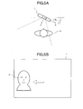
- FIG. 5A shows the operation input device 1 having rotated around the Z axis from the reference position, showing the user U and the operation input device 1 viewed from thereabove (the Z axial negative direction side).
- FIG. 5B shows a captured image I captured in the condition shown in FIG. 5A .
- the operation input device 1 rotates around the Z-axis
- the user U moves in the left-right direction when viewed from the image capturing unit 12, and accordingly, the face position Pf moves in the left-right direction relative to the reference face position Po in the captured image I.
- the function f (x) may be a correction function determined in accordance with the structure of the image capturing unit 12, lens characteristic, and the like.
- the pitch angle ⁇ p indicates the rotation angle of the operation input device 1 relative to the reference posture with the X-axis as the rotation axis.
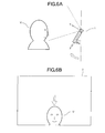
- FIG. 6A shows the operation input device 1 having rotated around the X axis from the reference posture, showing the user U and the operation input device 1 viewed from a lateral side thereof (the X axial positive direction side).
- FIG. 6B shows a captured image I captured in the condition shown in FIG. 6A .
- the operation input device 1 rotates around the X-axis
- the user U moves in the up-down direction when viewed from the image capturing unit 12, and accordingly, the face position Pf moves in the up-down direction relative to the reference face position Po in the captured image I.
- the posture parameter calculating unit 22b calculates the pitch angle ⁇ p, using a predetermined function, based on the y-coordinate value yf of the face position Pf.
- the function g (y) may be the same function as the function f(x).
- the posture parameter calculating unit 22b calculates the roll angle ⁇ r and the pitch angle ⁇ p, based on the face position Pf in the captured image I. These posture parameters indicate the inclination of the operation input device 1 relative to the direction from the image capturing unit 12 to the user U.
- the roll angle ⁇ r and the pitch angle ⁇ p are calculated, using values obtained by dividing the coordinate values xf and yf by the maximum coordinate values x max and y max , respectively.
- the origin of the position coordinate may be positioned different from the reference face position Po.
- any of the four corners of the captured image I may be determined as the origin in expressing the coordinate values of the face position Pf.
- the position coordinates of the reference face position Po are denoted as (xo, yo)
- calculation of the roll angle ⁇ r and the pitch angle ⁇ p, using (xf-xo) and (yf-yo) instead of xf and xf in the above mentioned respective expressions can provide a rotation angle relative to the reference posture.
- the yaw angle ⁇ y indicates the rotation angle of the operation input device 1 relative to the reference posture with the Y-axis as the rotation axis. That is, the yaw angle ⁇ y indicates the inclination of the operation input device 1 on a plane perpendicular to the image capturing direction Dc.
- FIG. 7A shows the operation input device 1 having rotated around the Y-axis from the reference posture, showing the user U and the operation input device 1 viewed from the back surface side of the operation input device 1 (the Y-axial negative direction side).
- FIG. 7B shows a captured image I captured in the condition shown in FIG. 7A .
- the coefficients a1, a2, and a3 may be fixed values that are determined in advance according to an application program or the like or a value that is changeable according to a designation by the user U.
- the coefficients a1 and a2 may be values that are changed based on the size (the size of a user U's face here) of a target object, the size being obtained in image analysis by the image analysis unit 22a. For example, when there is a slight difference between the actual position of the user U's face and an assumed position in the reference posture (that is, when the center position of the user U's face is slightly deviated from the straight line extending in the image capturing direction Dc), the difference may influence differently depending on the distance between the user U and the image capturing unit 12.
- the face position Pf may move by a smaller amount, compared to a case in which the distance between the user U and the image capturing unit 12 is relatively short, in response to the same amount of inclination of the operation input device 1.
- the size of an area occupied by the user U's face in the captured image I is also specified in specification of the face position Pf and the face direction Df by the image analyzing unit 22a, and the distance from the image capturing unit 12 to the user U can be estimated based on the size of the face area. Therefore, when the coefficients a1 and a2 are determined based on the size of the face area, the posture parameter calculating unit 22b can calculate the roll angle ⁇ r and the pitch angle ⁇ p that reflect a change in the posture of the operation input device 1, while reducing the influence due to the above described difference.
- the posture parameter calculating unit 22b may determine smaller values for the coefficients a1 and a2 with respect to a larger face area specified by the image analyzing unit 22a. Note that the posture parameter calculating unit 22b may use not only the size of the face area but also any other input information, such as parallax information or the like, in estimation of the distance to the user U's face.
- the posture parameter is calculated on the premise that the user U changes the orientation of the operation input device 1 but not the position itself of the operation input device 1 relative to the user U (that is, the image capturing position is not changed, while the image capturing direction Dc of the image capturing unit 12 is changed).
- the face position Pf in the captured image I will move. Therefore, sole use of information on the face position Pf in the captured image I may not be able to discriminate between a case in which the user U rotates the operation input device 1 and a case in which the user U moves in parallel the operation input device 1.
- the posture determining unit 22 may determine a change in the orientation of the target object relative to the direction extending from the image capturing unit 12 to a target object (the user U's face here), and based on the change determined in the orientation of the target object, determine whether or not the inclination of the operation input device 1 has been changed.
- the image analyzing unit 22a determines the direction in which the front of the user U's face is directed. This determination can be made by specifying the position of a characteristic point, such as an eye, the nose, and the like, in the face area, and comparing the distribution (an extent of deviation) of the specified characteristic points in the face area with a reference value.
- FIG. 8A shows the user U and the operation input device 1 viewed thereabove, similar to FIG. 5A , in which only the position, but the orientation, of the operation input device 1 has been changed.
- FIGS. 5A and 6A when the user U changes the orientation alone of the operation input device 1, the face position Pf in the captured image I moves from the middle toward an outer edge of the captured image I.
- the position itself of the user U's face relative to the lens of the image capturing unit 12 remains unchanged in the actual space. That is, the front side of the user U's face is kept directed to the lens of the image capturing unit 12, and as shown in FIGS.
- the direction in which the front side of the user U's face is directed in the captured images I is rarely changed.
- the direction in which the front side of the user U's face is directed moves departing from the lens of the image capturing unit 12. That is, as shown in FIG. 8B , as the operation input device 1 moves, the front side of the user U's face comes to be directed more outward of the captured image I.
- the posture parameter calculating unit 22b analyzes the face image contained in the captured image I to calculate the angle of the forward direction of the user U's face relative to the direction from the user U to the image capturing unit 12. Specifically, the posture parameter calculating unit 22b may calculate the angle of the forward direction of the face, based on, e.g., distribution of the positions of parts, such as an eye, the nose, and the like, contained in the face, brightness distribution, color distribution, heat distribution, distance distribution, and so forth, in the face area.
- the posture parameter calculating unit 22b determines that the operation input device 1 has moved in parallel by an amount corresponding to the angle calculated, and subtracts an amount attributed to the parallel movement from the position coordinate values xf, yf of the face position Pf for correction. Thereafter, the posture parameter calculating unit 22b calculates the above described roll angle ⁇ r and pitch angle ⁇ p, using the corrected values xf and yf. In this manner, when the face position Pf in the captured image I is changed, it is possible to separate an amount of change attributed to the parallel movement of the operation input device 1 and that attributed to the change in the inclination of the operation input device 1, and to calculate the amount of the change in the inclination of the operation input device 1. Note that the posture parameter calculating unit 22b may specify the angle of the forward direction of an eye, the nose, or the like, contained in the face, rather than the entire face, and calculate the amount of parallel movement of the operation input device 1, based on the specified angle.
- the posture parameter calculating unit 22b may determine a parallel movement of the operation input device 1, based on the movement of the background image contained in the captured image I. That is, when the user U moves in parallel the operation input device 1, not only the position of the user U in the captured image I but also the entire background image of the user U will move in parallel. However, when the user U only inclines the operation input device 1, parallel movement of the entire background is not resulted, but the background image may be only distorted. In view of the above, it is possible to specify an amount by which the operation input device 1 has moved in parallel by comparing the background image in the captured image I with that in a past captured image I and thereby analyzing a change in the background image. Such analysis can be realized using the KLT method (Kanade-Lucas-Tomasi Feature Tracker) and so forth.
- the posture determining unit 22 can calculate the distance from the image capturing unit 12 to the user U' s face, based on the size of the face area. Using a change in the distance as time passes, the posture determining unit 22 can detect the user U's operation of, e.g., swinging the operation input device 1 in the front-back direction. As described above, the posture determining unit 22 may detect not only rotation (change in the inclination) of the operation input device 1 around the respective X, Y, and Z axes, but also movement of the operation input device 1 along the respective X, Y, and Z axes, then calculate the speed and acceleration of each movement, and output to the displayed image update unit 23.
- the displayed image update unit 23 carries out a process of updating an image shown on the display unit 11, based on the result of posture determination by the posture determining unit 22. Specifically, the displayed image update unit 23 updates the displayed image, using as an operation input the value of the posture parameter calculated by the posture parameter calculating unit 22b. For example, the displayed image update unit 23 may carry out a process of moving a user object placed in a virtual 3D space or the position of the point of view defined in the virtual 3D space, based on the inclination direction and amount of the operation input device 1 specified based on the values of the roll angle ⁇ r and pitch angle ⁇ p, then produces an image reflecting the result of the process, and shows on the display unit 11. With the above, the operation input device 1 can execute an application program, such as a game application program, according to an operation input by the user U for changing the posture of the operation input device 1, and present the result to the user U.
- an application program such as a game application program
- the display image update unit 23 may show the captured image I itself captured by the image capturing unit 12 in a partial area on the display unit 11, together with the result of the process carried out based on the value of the posture parameter.
- the displayed image update unit 23 may show an image indicative of the result of analysis by the image analyzing unit 22a (that is, the face position Pf, face direction Df, and the like, of the user U specified in the captured image I) on the display unit 11.
- the user U can change the posture of the operation input device 1 while checking a change occurred to the captured image I in response to an operation input by the user U for changing the posture of the operation input device 1. This facilitates operation input.
- showing a horizontally reversed image as the captured image I enables readily and intuitive recognizition by the user U of a change in the face position Pf that has occurred in accordance with a change in the posture of the operation input device 1.
- the reference posture of the operation input device 1 is determined in advance such that the reference face position Po coincides with the center of the captured image I
- the reference posture may be determined at the start of execution of an application program or the like.
- the user U may operate the operating member 13 according to an instruction shown on the screen while holding the operation input device 1 in any desired posture, and the operation input device 1 may determine as the reference face position Po and the reference face direction Do the face position Pf and the face direction Df at the time when the operating member 13 is operated. Thereafter, a change of the operation input device 1 relative to the reference posture can be determined based on a change in the face position Pf relative to the reference face position Po and that in the face direction Df relative to the reference face direction Do.
- the posture determining unit 22 may fail specification of the user U's face in the captured image I and thus calculation of the posture parameter.
- the posture determining unit 22 may assume that the operation input device 1 remains at the posture determined based on the captured image I immediately before the failed specification of the user U's face. That is, the posture determining unit 22 keeps outputting the value of the last calculated posture parameter to the displayed image update unit 23 until following success in specification of the user U's face in the captured image I.
- the posture determining unit 22 may reset the change in the posture, and output a posture parameter identical to that which is to be output when the posture of the operation input device 1 returns to the reference posture.
- posture determination can be achieved based on a captured image I captured by the image capturing unit 12, similarly to a case in which such a sensor is used.
- the image capturing unit 12 is not limited to a CCD camera, and may be a camera for determining light, such as infrared radiation or the like, other than visible light, a 3D camera, and the like. Using such a camera, the operation input device 1 can obtain parallax information, information on heat and distance distribution in the captured image I, and the like.
- the image analyzing unit 22a specifies the user U's face contained in a captured image I in a face recognition process.
- face recognition is not mandatory.
- the image analyzing unit 22a may specify the contour of a person to thereby specify the position and inclination of the head of the person in a captured image I. In this case, use of the orientation of a shoulder line or the like can realize accurate determination of the inclination of the head in the captured image I.
- the image analyzing unit 22a may specify the position and orientation of a part (e.g., an eye, the nose, and the like) of the user U's face, rather than the entire face, and the posture parameter calculating unit 22b may calculate the value of the posture parameter, based on the specified position and orientation of the part of the face.
- a part e.g., an eye, the nose, and the like
- the image analyzing unit 22a may specify a person other than the user U holding the operation input device 1. That is, as described above, the lens of the image capturing unit 12 can rotate to be directed to the side of the back surface of the operation input device 1. With the image capturing direction Dc of the image capturing unit 12 directed to the side of the back surface of the operation input device 1, the posture determining unit 22 can obtain a captured image I containing a person other than the user U, and determine the posture of the operation input device 1, based on the position and orientation of the person contained in the captured image I.
- the posture determining unit 22 may reverse the captured image I in the left-right direction before analyzing the image to thereby correct the influence due to the reversed image capturing direction Dc.
- the posture determining unit 22 may specify a target object other than a person, and determine the posture of the operation input device 1, based on the position and orientation of the target object. Alternatively, a change in the posture of the operation input device 1 may be determined based on the movement and rotation of a characteristic point specified in the captured image I.
- the posture determining unit 22 calculates the values of the rotation angles ⁇ r, ⁇ p, and ⁇ y, and outputs as posture parameters to the displayed image update unit 23, this is not limiting. That is, the posture determining unit 22 may calculate another posture parameter.
- the operation input device 1 according to this embodiment is used instead of an operation input device having a posture determining sensor, such as an acceleration sensor, the calculated values of the rotation angles ⁇ r, ⁇ p, and ⁇ y may be first converted into values that are assumed to be output values from an acceleration sensor or the like before being output to the displayed image update unit 23.
- the user U can realize an identical process through an identical operation both when using an operation input device having a posture determining sensor and when using the operation input device 1 according to this embodiment, without changing the content of a process of the displayed image update unit 23 from a conventional process.
- an output of an acceleration sensor will change depending on the relationship between the vertical direction, in which the gravity acceleration is caused, and the orientation of the operation input device 1. Therefore, in emulation of an output from an acceleration sensor, using the operation input device 1 according to this embodiment, it is not possible to completely reproduce an output of the acceleration sensor if the vertical direction cannot be specified.
- some programs for carrying out a process using an output of an acceleration sensor may use posture information on the operation input device 1 specified based on the relationship with gravity acceleration as mere information on relative inclination relative to the reference posture or on change in the inclination as time passes. According to such a program, the real vertical direction corresponds to which direction relative to the operation input device 1 does not matter.
- the posture determining unit 22 calculates acceleration relative to a respective reference axis that will be caused when gravity is caused in that direction, using the value of the respective rotation angle ⁇ r, ⁇ p, and ⁇ y, and outputs the calculated acceleration value to the displayed image update unit 23.
- the user U may freely determine that a change in the posture of the operation input device 1 according to this embodiment relative to which direction corresponds to a change in the posture of an operation input device having a posture determining sensor relative to which direction.
- the operation input device 1 allocates each of the rotation angles ⁇ r, ⁇ p, and ⁇ y formed with the respective X, Y, and Z axes set on the operation input device 1 as the rotation axis to a rotation angle formed with any of the X, Y, and Z axes set on an operation input device having a posture determining sensor as the rotation axis.
- the user U can input an operation by inclining the operation input device 1 in a manner that facilities operation by the user U, irrespective of the shape of the operation input device 1.
- the operation input device 1 may allocate each of the rotation angles ⁇ r, ⁇ p, and ⁇ y to a rotation angle formed with any of the reference axes of an operation input device to be emulated as the rotation axis.
- the operation input device 1 determines whether the user holds the operation input device 1 in the portrait orientation or the landscape orientation, based on the orientation of the face determined or a designation by the application program. Then, the allocation of the rotation angle is determined, based on the result of the determination. With the above, the user can input an operation by inclining the operation input device 1 while holding the operation input device 1 either in the portrait or landscape orientation without being aware of the orientation of the operation input device 1.
- the operation input device 1 itself determines the posture thereof, based on a captured image I.
- another information processing device 31 connected to an operation input device 32 determines the posture of the operation input device 32 and carry out an information process, based on the result of the posture determination.
- the operation input device 32 may be a controller of a consumer game device, and used to input an operation by the user U to the information processing device 31.
- the information processing device 31 may be, e.g., a consumer game device, and carries out various processes, based on an operation input by the user U via the operation input device 32, and shows the result of the process on the screen of a display unit 33, such as a television receiver or the like.
- an image capturing unit 34 is provided on the external surface of the operation input device 32.
- the operation input device 32 has a communication unit 35, so that a captured image I captured by the image capturing unit 34 is sent to the information processing device 31 via the communication unit 35.
- the information processing device 31 comprises a control unit 36, a storage unit 37, and a communication unit 38, and the control unit 36 carries out an information process according to a program stored in the storage unit 37.
- the communication unit 38 carries out data communication with the communication unit 35 of the operation input device 32.
- control unit 36 of the information processing device 31 can determine the posture of the operation input device 32 by carrying out a process identical to that which is carried out with the above described operation input device 1. That is, the control unit 36 obtains, via the communication unit 35 and the communication unit 38, a captured image I captured by the image capturing unit 34, then determines the posture of the operation input device 32, based on the obtained result of analysis on the captured image I, and carries out a process based on the posture determined.
Landscapes
- Engineering & Computer Science (AREA)
- Theoretical Computer Science (AREA)
- General Engineering & Computer Science (AREA)
- Human Computer Interaction (AREA)
- Physics & Mathematics (AREA)
- General Physics & Mathematics (AREA)
- Computer Hardware Design (AREA)
- User Interface Of Digital Computer (AREA)
- Image Processing (AREA)
- Length Measuring Devices By Optical Means (AREA)
- Position Input By Displaying (AREA)
Abstract
Description
- The present invention relates to an operation input device for use by a user while being held by his/her hand, an information processing device connected to the operation input device, a posture determining method for the operation input device, and an information storage medium.
- Some of the operation input devices, such as a controller of a consumer game device, that are used by a user to input an operation have a posture determining sensor, such as an acceleration sensor, a gyro sensor, and the like, for determining the posture of the operation input device (see, e.g.Patent Document 1). Using such an operation input device, a user can input various operations not only by pressing an operation button but also inclining or moving the operation input device itself. Some application programs, such as a game application program, are available for carrying out a process according to such an operation input by inclining an operation input device.
-
- Patent Literature 1:
U.S. Patent Application Publication 2007/0260727 - However, some operation input devices do not have such a posture determining sensor. An application program that is premised on operation input through posture determination cannot be used in such an operation input device.
- The present invention has been conceived in view of the above described situation, and one object thereof is to provide an operation input device, an information processing device, a posture determining method for the operation input device, a program, and an information storage medium capable of operation input by changing the posture of the operation input device despite absence of a posture determining sensor.
- An operation input device according to the present invention comprises a captured image obtaining unit for obtaining a captured image captured by an image capturing unit provided to the operation input device, and a posture determining unit for determining the posture of the operation input device, based on the result of analysis on the captured image obtained.
- An information processing device according to the present invention is connected to an operation input device for use by a user while being held by the user's hand, and comprises a captured image obtaining unit for obtaining a captured image captured by an image capturing unit provided to the operation input device, and a posture determining unit for determining the posture of the operation input device, based on the result of analysis on the captured image obtained.
- A posture determining method for an operation input device according to the present invention comprises a step of obtaining a captured image captured by an image capturing unit provided to the operation input device, and a step of determining the posture of the operation input device, based on the result of analysis on the captured image obtained.
- An information storage medium according to the present invention is a computer readable information storage medium storing a program for causing a computer to function as a captured image obtaining unit for obtaining a captured image captured by an image capturing unit provided to the operation input device, and a posture determining unit for determining the posture of the operation input device, based on the result of analysis on the captured image obtained.
-
-
FIG. 1 is a perspective view showing external appearance of an operation input device according to a first embodiment of the present invention; -
FIG. 2 is a block diagram showing an internal structure of the operation input device according to this embodiment; -
FIG. 3 is a functional block diagram showing a functional example of the operation input device according to this embodiment; -
FIG. 4 is a diagram showing one example of a captured image containing the face of a user; -
FIG. 5A is a diagram showing the operation input device having rotated around the Z axis relative to a reference posture; -
FIG. 5B is a diagram showing a captured image in the condition shown inFIG. 5A ; -
FIG. 6A is a diagram showing the operation input device having rotated around the X axis relative to the reference posture; -
FIG. 6B is a diagram showing a captured image in the condition shown inFIG. 6A ; -
FIG. 7A is a diagram showing the operation input device having rotated around the Y axis relative to the reference posture; -
FIG. 7B is a diagram showing a captured image in the condition shown inFIG. 7A ; -
FIG. 8A is a diagram showing the operation input device having moved in parallel; -
FIG. 8B is a diagram showing a captured image in the condition shown inFIG. 8A ; and -
FIG. 9 is a structural block diagram of an information processing system including the information processing device according to a second embodiment of the present invention. - In the following, an embodiment of the present invention will be described in detail with reference to the accompanying drawings.
-
FIG. 1 is a perspective view showing external appearance of anoperation input device 1 according to a first embodiment of the present invention. In this embodiment, it is assumed that theoperation input device 1 is a portable game device for use by a user U while being held by his/her hand. - As shown in the diagram, the
enclosure 10 of theoperation input device 1 has a substantially rectangular panel-like shape as a whole, and has adisplay unit 11 formed on the surface thereof. Animage capturing unit 12 is attached at the top of theenclosure 10. Note that it is assumed here that the landscape direction (the longitudinal direction) of theoperation input device 1 corresponds to the X-axial direction, the portrait direction to the Z-axial direction, and the depth direction to the Y-axial direction. - The
display unit 11 may be any of various image display devices, such as a liquid crystal display panel, an organic EL display panel, and the like. Theimage capturing unit 12 is a CCD camera or the like, and captures an image of an object around theoperation input device 1. Specifically, inFIG. 1 , the lens of theimage capturing unit 12 is directed in the forward direction (the Y-axial positive direction) of theoperation input device 1, and captures an image with the forward direction as an image capturing direction Dc. Note that the lens of theimage capturing unit 12 is rotatable by 180 degrees with the X-axial direction as the rotation axis. Accordingly, the image capturing direction Dc of theimage capturing unit 12 will change from the Y-axial positive direction via the Z-axial negative direction to the Y-axial negative direction (a direction toward the side of the rear surface of the operation input device 1). - The
operation input device 1 hasvarious operating members 13, such as an operation button, an analogue stick, and the like, formed on the surface of theenclosure 10 thereof. A user U can operate theseoperating members 13 to thereby input an operation to theoperation input device 1. - As shown in
FIG. 2 , acontrol unit 14 and astorage unit 15 are provided in theoperation input device 1. - The
control unit 14 is a CPU or the like, and carries out various information processes according to a program stored in thestorage unit 15. In this embodiment, thecontrol unit 14 determines the posture of theoperation input device 1, based on an image captured by theimage capturing unit 12, and carries out a process of updating a screen image shown on thedisplay unit 11, using the result of determination as an operation input by the user U. Content of the process carried out by thecontrol unit 14 will be described later. - The
storage unit 15 comprises a memory device, such as a RAM, a ROM, or the like, or a hard disk drive or the like, and stores a program to be executed by thecontrol unit 14 and various data. Thestorage unit 15 operates also as a working memory of thecontrol unit 14. - As shown in
FIG. 3 , theoperation input device 1 functionally comprises a capturedimage obtaining unit 21, aposture determining unit 22, and a displayedimage update unit 23. In this embodiment, theposture determining unit 22 comprises animage analyzing unit 22a and a postureparameter calculating unit 22b. These functions are realized by thecontrol unit 14 by executing a program stored in thestorage unit 15. The program may be provided to theoperation input device 1 via a communication network, such as the Internet or the like, or as being stored in any of various computer readable information storage media, such as an optical disk, a memory card, and the like. - The captured
image obtaining unit 21 obtains a captured image I captured by theimage capturing unit 12. Specifically, the capturedimage obtaining unit 21 obtains a captured image I at each time point for every predetermined period of time while theoperation input device 1 continues a posture determining process. - Note that the captured image I may be either a still image or a frame image in a motion image at one time point. That is, the
image capturing unit 12 may capture a still image at a time designated by the capturedimage obtaining unit 21. Alternatively, theimage capturing unit 12 may keep capturing a motion image, and the capturedimage obtaining unit 21 may extract a frame image as a captured image I from the motion image. - The
posture determining unit 22 determines the posture of theoperation input device 1, based on the result of analysis on the captured image I obtained by the capturedimage obtaining unit 21. - Specifically, the
image analyzing unit 22a analyzes each captured image I captured by the capturedimage obtaining unit 21 for every predetermined period of time, and specifies an object (a target object) contained in the captured image I. The target object may be anything available to be used as a mark in determination of the posture of theoperation input device 1, of which position and orientation in the captured image I can be specified. It is assumed here that a target object to be specified by theimage analyzing unit 22a is the face of a user U holding theoperation input device 1. A user U of theoperation input device 1 holds theoperation input device 1 with his/her both hands when using such that theoperation input device 1 is located in front of his/her own face in order to view an image shown on thedisplay unit 11. In the above, as the user U's face is positioned in the image capturing direction Dc of theimage capturing unit 12, it is assumed that the user U's face is seen in the captured image I. - The
image analyzing unit 22a specifies the center position of the user U's face in the captured image I (hereinafter referred to as a face position Pf). Further, theimage analyzing unit 22a additionally specifies the inclination of the user U's face in the captured image (hereinafter referred to as a face direction Df). It is assumed here that the face direction Df is defined as a direction in which the top of the user U's head is directed in the captured image I. The face position Pf and the face direction Df can be specified using a known face recognition technique. Specifically, theimage analyzing unit 22a may detect a part, such as an eye, the nose, and the like, contained in a face, or analyze brightness distribution, color distribution, heat distribution, distance distribution, and so forth, in the captured image I to specify the face position Pf and the face direction Df. Note that when two or more faces are detected in the captured image I, theimage analyzing unit 22a may specify, e.g., the largest face in the size in the captured image I as the user U's face.FIG. 4 shows the positional coordinates (xf, yf) of the face position Pf and the angular value θf of the face direction Df specified in such image analysis. Note that the positional coordinates (xf, yf) of the face position Pf are expressed in a coordinate system of which origin coincides with the center position of the captured image I. The angular value θf of the face direction Df is expressed as an angle formed by the direction of the top of the user U's head relative to the upward direction (the vertical direction) of the captured image I. - Based on the result of analysis by the
image analyzing unit 22a, the postureparameter calculating unit 22b calculates the value of a posture parameter indicative of the posture of theoperation input device 1. Specifically, based on at least one of the face position Pf and the face direction Df specified by theimage analyzing unit 22a, the postureparameter calculating unit 22b determines the posture of theoperation input device 1. It is assumed here that the postureparameter calculating unit 22b calculates a roll angle θr, a pitch angle θp, and a yaw angle θy as posture parameters, based on the face position Pf and the face direction Df. These posture parameters, as to be described later in detail, indicate rotation angles of theoperation input device 1 relative to the reference posture with the respective reference axes set on theoperation input device 1 as the rotation axis. - Note that it is assumed here that the reference posture of the
operation input device 1 is such that the center of the user U's face is present on a straight line extending in the image capturing direction Dc and that the upward direction (the Z axial negative direction) of theoperation input device 1 coincides with the direction from the user U's face toward the top of his/her head. That is, when theoperation input device 1 is in the reference position, the face position Pf is present in the center of the captured image I, and the face direction Df extends in the upward direction of the captured image I. The face position Pf and the face direction Df of theoperation input device 1 in the reference posture will be hereinafter denoted as a reference face position Po and a reference face direction Do, respectively. - The roll angle θr indicates the rotation angle of the
operation input device 1 relative to the reference posture with the Z axis as the rotation axis.FIG. 5A shows theoperation input device 1 having rotated around the Z axis from the reference position, showing the user U and theoperation input device 1 viewed from thereabove (the Z axial negative direction side).FIG. 5B shows a captured image I captured in the condition shown inFIG. 5A . As shown in these diagrams, when theoperation input device 1 rotates around the Z-axis, the user U moves in the left-right direction when viewed from theimage capturing unit 12, and accordingly, the face position Pf moves in the left-right direction relative to the reference face position Po in the captured image I. Then, the postureparameter calculating unit 22b calculates the roll angle θr, using a predetermined function, based on the x coordinate value xf of the face position Pf. For example, the postureparameter calculating unit 22b calculates the roll angle θr as the expression θr=a1·f (xf/xmax), wherein a1 is a predetermined coefficient, xmax is the maximum value of the x-coordinate value, and f(x) is a predetermined function. As one example, the postureparameter calculating unit 22b may calculate the roll angle θr as the expression θr=a1·xf/xmax, based on an assumption that the roll angle θr is proportional to the x-coordinate value xf. The function f (x) may be a correction function determined in accordance with the structure of theimage capturing unit 12, lens characteristic, and the like. - The pitch angle θp indicates the rotation angle of the
operation input device 1 relative to the reference posture with the X-axis as the rotation axis.FIG. 6A shows theoperation input device 1 having rotated around the X axis from the reference posture, showing the user U and theoperation input device 1 viewed from a lateral side thereof (the X axial positive direction side).FIG. 6B shows a captured image I captured in the condition shown inFIG. 6A . As shown in these diagrams, when theoperation input device 1 rotates around the X-axis, the user U moves in the up-down direction when viewed from theimage capturing unit 12, and accordingly, the face position Pf moves in the up-down direction relative to the reference face position Po in the captured image I. Then, the postureparameter calculating unit 22b calculates the pitch angle θp, using a predetermined function, based on the y-coordinate value yf of the face position Pf. For example, the postureparameter calculating unit 22b may calculate the pitch angle θp as the expression θp=a2·g (yf/ymax), wherein, similar to the case of the roll angle θr, a2 is a predetermined coefficient, ymax is the maximum value of the y-coordinate value, and g(y) is a predetermined function. Note that the function g (y) may be the same function as the function f(x). As one example, the postureparameter calculating unit 22b may calculate the pitch angle θp as the expression θp=a2·yf/ymax, based on the assumption that the pitch angle θp is proportional to the y-coordinate value yf. - As described above, the posture
parameter calculating unit 22b calculates the roll angle θr and the pitch angle θp, based on the face position Pf in the captured image I. These posture parameters indicate the inclination of theoperation input device 1 relative to the direction from theimage capturing unit 12 to the user U. Note that the roll angle θr and the pitch angle θp are calculated, using values obtained by dividing the coordinate values xf and yf by the maximum coordinate values xmax and ymax, respectively. With the above, the role angle θr and the pitch angle θp can be calculated, based on the value obtained by normalizing position coordinates in the captured image I. In the above, a1 and a2 may be the same value. Further, the role angle θr and the pitch angle θp may be calculated as θr=a1·f(xf) and θp=a2·g(yf), respectively, without using xmax and ymax. - Note that although it is determined in the above that the origin of the position coordinate coincides with the reference face position Po, the origin of the position coordinate may be positioned different from the reference face position Po. For example, any of the four corners of the captured image I may be determined as the origin in expressing the coordinate values of the face position Pf. In this case, while the position coordinates of the reference face position Po are denoted as (xo, yo), calculation of the roll angle θr and the pitch angle θp, using (xf-xo) and (yf-yo) instead of xf and xf in the above mentioned respective expressions can provide a rotation angle relative to the reference posture.
- Meanwhile, the yaw angle θy indicates the rotation angle of the
operation input device 1 relative to the reference posture with the Y-axis as the rotation axis. That is, the yaw angle θy indicates the inclination of theoperation input device 1 on a plane perpendicular to the image capturing direction Dc.FIG. 7A shows theoperation input device 1 having rotated around the Y-axis from the reference posture, showing the user U and theoperation input device 1 viewed from the back surface side of the operation input device 1 (the Y-axial negative direction side).FIG. 7B shows a captured image I captured in the condition shown inFIG. 7A . As shown in these diagrams, when theoperation input device 1 rotates around the Y-axis, the face direction Df in the captured image I rotates in the reverse direction. Therefore, the postureparameter calculating unit 22b calculates the yaw angle θy, using a predetermined function, based on the angular value θf of the face direction Df. For example, the postureparameter calculation unit 22b calculates the yaw angle θy as the expression θy=a3·h(θf), wherein a3 is a predetermined coefficient and h(θ) is a predetermined function. As one example, the postureparameter calculating unit 22b may calculate the yaw angle θy as the expression θy=a3 · θf, based on an assumption that the yaw angle θy is proportional to the angular value θf. - Note that in the above description, the coefficients a1, a2, and a3 may be fixed values that are determined in advance according to an application program or the like or a value that is changeable according to a designation by the user U.
- In particular, the coefficients a1 and a2 may be values that are changed based on the size (the size of a user U's face here) of a target object, the size being obtained in image analysis by the
image analysis unit 22a. For example, when there is a slight difference between the actual position of the user U's face and an assumed position in the reference posture (that is, when the center position of the user U's face is slightly deviated from the straight line extending in the image capturing direction Dc), the difference may influence differently depending on the distance between the user U and theimage capturing unit 12. That is, for a relatively short distance between the user U and theimage capturing unit 12, even a slight change in the inclination of theoperation input device 1 may result in a significant movement of the face position Pf in the captured image I. However, for a relatively long distance between the user U and theimage capturing unit 12, the face position Pf may move by a smaller amount, compared to a case in which the distance between the user U and theimage capturing unit 12 is relatively short, in response to the same amount of inclination of theoperation input device 1. It should be noted here that the size of an area occupied by the user U's face in the captured image I is also specified in specification of the face position Pf and the face direction Df by theimage analyzing unit 22a, and the distance from theimage capturing unit 12 to the user U can be estimated based on the size of the face area. Therefore, when the coefficients a1 and a2 are determined based on the size of the face area, the postureparameter calculating unit 22b can calculate the roll angle θr and the pitch angle θp that reflect a change in the posture of theoperation input device 1, while reducing the influence due to the above described difference. Specifically, the postureparameter calculating unit 22b may determine smaller values for the coefficients a1 and a2 with respect to a larger face area specified by theimage analyzing unit 22a. Note that the postureparameter calculating unit 22b may use not only the size of the face area but also any other input information, such as parallax information or the like, in estimation of the distance to the user U's face. - In the above description, the posture parameter is calculated on the premise that the user U changes the orientation of the
operation input device 1 but not the position itself of theoperation input device 1 relative to the user U (that is, the image capturing position is not changed, while the image capturing direction Dc of theimage capturing unit 12 is changed). However, also when the user U should move in parallel the position of theoperation input device 1, the face position Pf in the captured image I will move. Therefore, sole use of information on the face position Pf in the captured image I may not be able to discriminate between a case in which the user U rotates theoperation input device 1 and a case in which the user U moves in parallel theoperation input device 1. - In view of the above, the
posture determining unit 22 may determine a change in the orientation of the target object relative to the direction extending from theimage capturing unit 12 to a target object (the user U's face here), and based on the change determined in the orientation of the target object, determine whether or not the inclination of theoperation input device 1 has been changed. Specifically, in specification of the user U's face contained in the captured image I, theimage analyzing unit 22a determines the direction in which the front of the user U's face is directed. This determination can be made by specifying the position of a characteristic point, such as an eye, the nose, and the like, in the face area, and comparing the distribution (an extent of deviation) of the specified characteristic points in the face area with a reference value. -
FIG. 8A shows the user U and theoperation input device 1 viewed thereabove, similar toFIG. 5A , in which only the position, but the orientation, of theoperation input device 1 has been changed. As shown inFIGS. 5A and6A , when the user U changes the orientation alone of theoperation input device 1, the face position Pf in the captured image I moves from the middle toward an outer edge of the captured image I. However, the position itself of the user U's face relative to the lens of theimage capturing unit 12 remains unchanged in the actual space. That is, the front side of the user U's face is kept directed to the lens of theimage capturing unit 12, and as shown inFIGS. 5B and6B , the direction in which the front side of the user U's face is directed in the captured images I is rarely changed. However, when the user U moves in parallel the position of theoperation input device 1, as shown inFIG. 8A , the direction in which the front side of the user U's face is directed moves departing from the lens of theimage capturing unit 12. That is, as shown inFIG. 8B , as theoperation input device 1 moves, the front side of the user U's face comes to be directed more outward of the captured image I. - In view of the above, the posture
parameter calculating unit 22b analyzes the face image contained in the captured image I to calculate the angle of the forward direction of the user U's face relative to the direction from the user U to theimage capturing unit 12. Specifically, the postureparameter calculating unit 22b may calculate the angle of the forward direction of the face, based on, e.g., distribution of the positions of parts, such as an eye, the nose, and the like, contained in the face, brightness distribution, color distribution, heat distribution, distance distribution, and so forth, in the face area. Then, the postureparameter calculating unit 22b determines that theoperation input device 1 has moved in parallel by an amount corresponding to the angle calculated, and subtracts an amount attributed to the parallel movement from the position coordinate values xf, yf of the face position Pf for correction. Thereafter, the postureparameter calculating unit 22b calculates the above described roll angle θr and pitch angle θp, using the corrected values xf and yf. In this manner, when the face position Pf in the captured image I is changed, it is possible to separate an amount of change attributed to the parallel movement of theoperation input device 1 and that attributed to the change in the inclination of theoperation input device 1, and to calculate the amount of the change in the inclination of theoperation input device 1. Note that the postureparameter calculating unit 22b may specify the angle of the forward direction of an eye, the nose, or the like, contained in the face, rather than the entire face, and calculate the amount of parallel movement of theoperation input device 1, based on the specified angle. - Alternatively, the posture
parameter calculating unit 22b may determine a parallel movement of theoperation input device 1, based on the movement of the background image contained in the captured image I. That is, when the user U moves in parallel theoperation input device 1, not only the position of the user U in the captured image I but also the entire background image of the user U will move in parallel. However, when the user U only inclines theoperation input device 1, parallel movement of the entire background is not resulted, but the background image may be only distorted. In view of the above, it is possible to specify an amount by which theoperation input device 1 has moved in parallel by comparing the background image in the captured image I with that in a past captured image I and thereby analyzing a change in the background image. Such analysis can be realized using the KLT method (Kanade-Lucas-Tomasi Feature Tracker) and so forth. - Note that, as described above, the
posture determining unit 22 can calculate the distance from theimage capturing unit 12 to the user U' s face, based on the size of the face area. Using a change in the distance as time passes, theposture determining unit 22 can detect the user U's operation of, e.g., swinging theoperation input device 1 in the front-back direction. As described above, theposture determining unit 22 may detect not only rotation (change in the inclination) of theoperation input device 1 around the respective X, Y, and Z axes, but also movement of theoperation input device 1 along the respective X, Y, and Z axes, then calculate the speed and acceleration of each movement, and output to the displayedimage update unit 23. - The displayed
image update unit 23 carries out a process of updating an image shown on thedisplay unit 11, based on the result of posture determination by theposture determining unit 22. Specifically, the displayedimage update unit 23 updates the displayed image, using as an operation input the value of the posture parameter calculated by the postureparameter calculating unit 22b. For example, the displayedimage update unit 23 may carry out a process of moving a user object placed in a virtual 3D space or the position of the point of view defined in the virtual 3D space, based on the inclination direction and amount of theoperation input device 1 specified based on the values of the roll angle θr and pitch angle θp, then produces an image reflecting the result of the process, and shows on thedisplay unit 11. With the above, theoperation input device 1 can execute an application program, such as a game application program, according to an operation input by the user U for changing the posture of theoperation input device 1, and present the result to the user U. - The display
image update unit 23 may show the captured image I itself captured by theimage capturing unit 12 in a partial area on thedisplay unit 11, together with the result of the process carried out based on the value of the posture parameter. Alternatively, the displayedimage update unit 23 may show an image indicative of the result of analysis by theimage analyzing unit 22a (that is, the face position Pf, face direction Df, and the like, of the user U specified in the captured image I) on thedisplay unit 11. With the above, the user U can change the posture of theoperation input device 1 while checking a change occurred to the captured image I in response to an operation input by the user U for changing the posture of theoperation input device 1. This facilitates operation input. In the above, showing a horizontally reversed image as the captured image I enables readily and intuitive recognizition by the user U of a change in the face position Pf that has occurred in accordance with a change in the posture of theoperation input device 1. - Although it is described in the above that the reference posture of the
operation input device 1 is determined in advance such that the reference face position Po coincides with the center of the captured image I, the reference posture may be determined at the start of execution of an application program or the like. For example, the user U may operate the operatingmember 13 according to an instruction shown on the screen while holding theoperation input device 1 in any desired posture, and theoperation input device 1 may determine as the reference face position Po and the reference face direction Do the face position Pf and the face direction Df at the time when the operatingmember 13 is operated. Thereafter, a change of theoperation input device 1 relative to the reference posture can be determined based on a change in the face position Pf relative to the reference face position Po and that in the face direction Df relative to the reference face direction Do. - In the above described posture determination, excessive inclination of the
operation input device 1 may possibly leave the user U's face outside the angle of view of theimage capturing unit 12, and consequently, theposture determining unit 22 may fail specification of the user U's face in the captured image I and thus calculation of the posture parameter. In such a case, theposture determining unit 22 may assume that theoperation input device 1 remains at the posture determined based on the captured image I immediately before the failed specification of the user U's face. That is, theposture determining unit 22 keeps outputting the value of the last calculated posture parameter to the displayedimage update unit 23 until following success in specification of the user U's face in the captured image I. Alternatively, upon failure in specification of the user U's face, theposture determining unit 22 may reset the change in the posture, and output a posture parameter identical to that which is to be output when the posture of theoperation input device 1 returns to the reference posture. - According to the
operation input device 1 according to the embodiment described above, even when a posture determining sensor, such as an acceleration sensor or the like, is not available, posture determination can be achieved based on a captured image I captured by theimage capturing unit 12, similarly to a case in which such a sensor is used. - Note that an embodiment of the present invention is not limited to the above described embodiment. For example, the
image capturing unit 12 is not limited to a CCD camera, and may be a camera for determining light, such as infrared radiation or the like, other than visible light, a 3D camera, and the like. Using such a camera, theoperation input device 1 can obtain parallax information, information on heat and distance distribution in the captured image I, and the like. - In the above description, the
image analyzing unit 22a specifies the user U's face contained in a captured image I in a face recognition process. However, face recognition is not mandatory. For example, theimage analyzing unit 22a may specify the contour of a person to thereby specify the position and inclination of the head of the person in a captured image I. In this case, use of the orientation of a shoulder line or the like can realize accurate determination of the inclination of the head in the captured image I. Further, theimage analyzing unit 22a may specify the position and orientation of a part (e.g., an eye, the nose, and the like) of the user U's face, rather than the entire face, and the postureparameter calculating unit 22b may calculate the value of the posture parameter, based on the specified position and orientation of the part of the face. - Further, the
image analyzing unit 22a may specify a person other than the user U holding theoperation input device 1. That is, as described above, the lens of theimage capturing unit 12 can rotate to be directed to the side of the back surface of theoperation input device 1. With the image capturing direction Dc of theimage capturing unit 12 directed to the side of the back surface of theoperation input device 1, theposture determining unit 22 can obtain a captured image I containing a person other than the user U, and determine the posture of theoperation input device 1, based on the position and orientation of the person contained in the captured image I. Note that, in this case, as the image capturing direction Dc of theimage capturing unit 12 relative to theoperation input device 1 is reversed from that which has been described in the above, the relationship between the position in the left-right direction of the face position Pf in the captured image I and the roll angle θr is reversed from that which has been described above. Further, the relationship between the rotation direction of the face direction Df and the yaw angle θy is also reversed. Thus, when the lens of theimage capturing unit 12 is directed toward the side of the back surface, theposture determining unit 22 may reverse the captured image I in the left-right direction before analyzing the image to thereby correct the influence due to the reversed image capturing direction Dc. - Further, the
posture determining unit 22 may specify a target object other than a person, and determine the posture of theoperation input device 1, based on the position and orientation of the target object. Alternatively, a change in the posture of theoperation input device 1 may be determined based on the movement and rotation of a characteristic point specified in the captured image I. - Although it is described in the above that the
posture determining unit 22 calculates the values of the rotation angles θr, θp, and θy, and outputs as posture parameters to the displayedimage update unit 23, this is not limiting. That is, theposture determining unit 22 may calculate another posture parameter. In particular, when theoperation input device 1 according to this embodiment is used instead of an operation input device having a posture determining sensor, such as an acceleration sensor, the calculated values of the rotation angles θr, θp, and θy may be first converted into values that are assumed to be output values from an acceleration sensor or the like before being output to the displayedimage update unit 23. With the above, in a case where the displayedimage update unit 23 is realized according to an application program, such as a game application program, the user U can realize an identical process through an identical operation both when using an operation input device having a posture determining sensor and when using theoperation input device 1 according to this embodiment, without changing the content of a process of the displayedimage update unit 23 from a conventional process. - Note that, e.g., an output of an acceleration sensor will change depending on the relationship between the vertical direction, in which the gravity acceleration is caused, and the orientation of the
operation input device 1. Therefore, in emulation of an output from an acceleration sensor, using theoperation input device 1 according to this embodiment, it is not possible to completely reproduce an output of the acceleration sensor if the vertical direction cannot be specified. However, some programs for carrying out a process using an output of an acceleration sensor may use posture information on theoperation input device 1 specified based on the relationship with gravity acceleration as mere information on relative inclination relative to the reference posture or on change in the inclination as time passes. According to such a program, the real vertical direction corresponds to which direction relative to theoperation input device 1 does not matter. In view of the above, after setting a virtual gravity direction in a predetermined direction, theposture determining unit 22 calculates acceleration relative to a respective reference axis that will be caused when gravity is caused in that direction, using the value of the respective rotation angle θr, θp, and θy, and outputs the calculated acceleration value to the displayedimage update unit 23. With the above, it is possible to realize a process of updating a displayed image through an operation identical to that which is carried out when using an operation input device having an acceleration sensor, without changing the content of the program for realizing the displayedimage update unit 23. - Note that in emulation of an operation input device having such a posture determining sensor, the user U may freely determine that a change in the posture of the
operation input device 1 according to this embodiment relative to which direction corresponds to a change in the posture of an operation input device having a posture determining sensor relative to which direction. For example, according to a designation by the user U, theoperation input device 1 allocates each of the rotation angles θr, θp, and θy formed with the respective X, Y, and Z axes set on theoperation input device 1 as the rotation axis to a rotation angle formed with any of the X, Y, and Z axes set on an operation input device having a posture determining sensor as the rotation axis. With the above, the user U can input an operation by inclining theoperation input device 1 in a manner that facilities operation by the user U, irrespective of the shape of theoperation input device 1. Alternatively, depending on the orientation of the user U's face determined by theimage analyzing unit 22a, a condition set in advance by an application program, or the like, theoperation input device 1 may allocate each of the rotation angles θr, θp, and θy to a rotation angle formed with any of the reference axes of an operation input device to be emulated as the rotation axis. For example, in a case where it is expected that a user holds theoperation input device 1 either in portrait orientation (with the longitudinal direction of theoperation input device 1 extending along the vertical direction) or landscape orientation (with the longitudinal direction of theoperation input device 1 extending in the user's left-right direction), theoperation input device 1 determines whether the user holds theoperation input device 1 in the portrait orientation or the landscape orientation, based on the orientation of the face determined or a designation by the application program. Then, the allocation of the rotation angle is determined, based on the result of the determination. With the above, the user can input an operation by inclining theoperation input device 1 while holding theoperation input device 1 either in the portrait or landscape orientation without being aware of the orientation of theoperation input device 1. - In the following, an information processing system including an
information processing device 31 according to a second embodiment of the present invention will be described referring toFIG. 9 . In the first embodiment, theoperation input device 1 itself determines the posture thereof, based on a captured image I. However, in the second embodiment, anotherinformation processing device 31 connected to anoperation input device 32 determines the posture of theoperation input device 32 and carry out an information process, based on the result of the posture determination. - Note that the
operation input device 32 may be a controller of a consumer game device, and used to input an operation by the user U to theinformation processing device 31. Theinformation processing device 31 may be, e.g., a consumer game device, and carries out various processes, based on an operation input by the user U via theoperation input device 32, and shows the result of the process on the screen of adisplay unit 33, such as a television receiver or the like. - In the example shown in
FIG. 9 , animage capturing unit 34 is provided on the external surface of theoperation input device 32. Theoperation input device 32 has acommunication unit 35, so that a captured image I captured by theimage capturing unit 34 is sent to theinformation processing device 31 via thecommunication unit 35. Theinformation processing device 31 comprises acontrol unit 36, astorage unit 37, and acommunication unit 38, and thecontrol unit 36 carries out an information process according to a program stored in thestorage unit 37. Thecommunication unit 38 carries out data communication with thecommunication unit 35 of theoperation input device 32. - In this example as well, the
control unit 36 of theinformation processing device 31 can determine the posture of theoperation input device 32 by carrying out a process identical to that which is carried out with the above describedoperation input device 1. That is, thecontrol unit 36 obtains, via thecommunication unit 35 and thecommunication unit 38, a captured image I captured by theimage capturing unit 34, then determines the posture of theoperation input device 32, based on the obtained result of analysis on the captured image I, and carries out a process based on the posture determined.
Claims (9)
- An operation input device for use by a user while being held by the user's hand, comprising:captured image obtaining means for obtaining a captured image captured by an image capturing unit provided to the operation input device; andposture determining means for determining posture of the operation input device, based on a result of analysis on the captured image obtained.
- The operation input device according to claim 1, wherein the posture determining means specifies a target object contained in the captured image obtained, and determines the posture of the operation input device, based on at least one of a position and orientation of the target object specified.
- The operation input device according to claim 2, wherein
the target object is an entirety or a part of a face of the user holding the operation input device, and
the posture determining means determines the posture of the operation input device, based on at least one of a position and orientation of the entirety or the part of the face of the user. - The operation input device according to claim 2, wherein the posture determining means determines inclination of the operation input device relative to a direction from the image capturing unit to the target object, based on a position of the target object in the captured image.
- The operation input device according to claim 4, wherein when the position of the target object in the captured image is changed, the posture determining means determines a change in orientation of the target object relative to the direction from the image capturing unit to the target object, and calculates an amount of change in the inclination of the operation input device relative to the direction from the image capturing unit to the target object, based on the change determined in the orientation of the image capturing image.
- The operation input device according to claim 1, wherein the posture determining means determines inclination of the operation input device on a plane perpendicular to an image capturing direction, based on orientation of the target object in the captured image.
- An information processing device connected to an operation input device for use by a user while being held by the user's hand, comprising:captured image obtaining means for obtaining a captured image captured by an image capturing unit provided to the operation input device; andposture determining means for determining posture of the operation input device, based on a result of analysis on the captured image obtained.
- A posture determining method for an operation input device, comprising:a step of obtaining a captured image captured by an image capturing unit provided to the operation input device; anda step of determining posture of the operation input device, based on a result of analysis on the captured image obtained.
- A computer readable information storage medium storing a program for causing a computer to function as:captured image obtaining means for obtaining a captured image captured by an image capturing unit provided to the operation input device; andposture determining means for determining posture of the operation input device, based on a result of analysis on the captured image obtained.
Applications Claiming Priority (2)
| Application Number | Priority Date | Filing Date | Title |
|---|---|---|---|
| JP2009252330A JP5437023B2 (en) | 2009-11-02 | 2009-11-02 | Operation input device |
| PCT/JP2010/061822 WO2011052270A1 (en) | 2009-11-02 | 2010-07-13 | Operation input device |
Publications (3)
| Publication Number | Publication Date |
|---|---|
| EP2498170A1 true EP2498170A1 (en) | 2012-09-12 |
| EP2498170A4 EP2498170A4 (en) | 2016-01-06 |
| EP2498170B1 EP2498170B1 (en) | 2019-09-25 |
Family
ID=43921701
Family Applications (1)
| Application Number | Title | Priority Date | Filing Date |
|---|---|---|---|
| EP10826405.2A Active EP2498170B1 (en) | 2009-11-02 | 2010-07-13 | Operation input device |
Country Status (5)
| Country | Link |
|---|---|
| US (1) | US20120212410A1 (en) |
| EP (1) | EP2498170B1 (en) |
| JP (1) | JP5437023B2 (en) |
| CN (1) | CN102725713A (en) |
| WO (1) | WO2011052270A1 (en) |
Families Citing this family (5)
| Publication number | Priority date | Publication date | Assignee | Title |
|---|---|---|---|---|
| JP5891659B2 (en) * | 2011-08-31 | 2016-03-23 | ソニー株式会社 | Operating device, information processing method thereof, and information processing device |
| US9407824B2 (en) * | 2012-11-01 | 2016-08-02 | Google Inc. | Multi-directional content capture on mobile devices |
| US9213419B1 (en) * | 2012-11-13 | 2015-12-15 | Amazon Technologies, Inc. | Orientation inclusive interface navigation |
| JP6547355B2 (en) * | 2015-03-20 | 2019-07-24 | 大日本印刷株式会社 | Printed product manufacturing device |
| JP2017129567A (en) * | 2016-01-20 | 2017-07-27 | キヤノン株式会社 | Information processing apparatus, information processing method, and program |
Family Cites Families (11)
| Publication number | Priority date | Publication date | Assignee | Title |
|---|---|---|---|---|
| JP3422383B2 (en) * | 1994-09-05 | 2003-06-30 | 株式会社タイトー | Method and apparatus for detecting relative position between video screen and gun in shooting game machine |
| JPH1173510A (en) * | 1997-08-29 | 1999-03-16 | Matsushita Electric Works Ltd | Position detecting device |
| US20020126090A1 (en) * | 2001-01-18 | 2002-09-12 | International Business Machines Corporation | Navigating and selecting a portion of a screen by utilizing a state of an object as viewed by a camera |
| EP1398601A3 (en) * | 2002-09-13 | 2014-05-07 | Canon Kabushiki Kaisha | Head up display for navigation purposes in a vehicle |
| JP3990619B2 (en) * | 2002-10-11 | 2007-10-17 | 株式会社東海理化電機製作所 | Face orientation detection device |
| JP2005100084A (en) * | 2003-09-25 | 2005-04-14 | Toshiba Corp | Image processing apparatus and method |
| JP4412714B2 (en) * | 2004-03-31 | 2010-02-10 | 株式会社バンダイナムコゲームス | Arrangement information detection system, game system, program, information storage medium, and arrangement information detection system control method |
| US20060192775A1 (en) * | 2005-02-25 | 2006-08-31 | Microsoft Corporation | Using detected visual cues to change computer system operating states |
| KR100643470B1 (en) * | 2005-09-29 | 2006-11-10 | 엘지전자 주식회사 | Graphic signal display device and method of portable terminal |
| JP2007304666A (en) | 2006-05-08 | 2007-11-22 | Sony Computer Entertainment Inc | Information output system and information output method |
| US20110102570A1 (en) * | 2008-04-14 | 2011-05-05 | Saar Wilf | Vision based pointing device emulation |
-
2009
- 2009-11-02 JP JP2009252330A patent/JP5437023B2/en active Active
-
2010
- 2010-07-13 WO PCT/JP2010/061822 patent/WO2011052270A1/en not_active Ceased
- 2010-07-13 CN CN2010800603263A patent/CN102725713A/en active Pending
- 2010-07-13 US US13/504,322 patent/US20120212410A1/en not_active Abandoned
- 2010-07-13 EP EP10826405.2A patent/EP2498170B1/en active Active
Non-Patent Citations (1)
| Title |
|---|
| See references of WO2011052270A1 * |
Also Published As
| Publication number | Publication date |
|---|---|
| EP2498170B1 (en) | 2019-09-25 |
| EP2498170A4 (en) | 2016-01-06 |
| WO2011052270A1 (en) | 2011-05-05 |
| JP5437023B2 (en) | 2014-03-12 |
| US20120212410A1 (en) | 2012-08-23 |
| CN102725713A (en) | 2012-10-10 |
| JP2011095228A (en) | 2011-05-12 |
Similar Documents
| Publication | Publication Date | Title |
|---|---|---|
| US10620712B2 (en) | Interactive input system and method | |
| US8310537B2 (en) | Detecting ego-motion on a mobile device displaying three-dimensional content | |
| JP4593968B2 (en) | Position and orientation measurement method and apparatus | |
| TWI550437B (en) | Apparatus capable of tangible interaction, article of manufacture, and method for tangible interaction | |
| EP3685248B1 (en) | Tracking of location and orientation of a virtual controller in a virtual reality system | |
| US11460916B2 (en) | Interface interaction apparatus and method | |
| US8686943B1 (en) | Two-dimensional method and system enabling three-dimensional user interaction with a device | |
| US20140354602A1 (en) | Interactive input system and method | |
| US10093280B2 (en) | Method of controlling a cursor by measurements of the attitude of a pointer and pointer implementing said method | |
| JP6242039B2 (en) | Apparatus and method for gyro controlled game viewpoint with automatic centering function | |
| KR20120023247A (en) | Portable apparatus and method for displaying 3d object | |
| TW201911133A (en) | Controller tracking for multiple degrees of freedom | |
| CN110489027B (en) | Handheld input device and display position control method and device of indication icon of handheld input device | |
| US20180225837A1 (en) | Scenario extraction method, object locating method and system thereof | |
| US20100188355A1 (en) | Apparatus and method for detecting an object pointed by a user | |
| EP2498170B1 (en) | Operation input device | |
| CN116205980A (en) | Method and device for positioning and tracking virtual reality in mobile space | |
| EP2107529A2 (en) | Storage medium storing image conversion programm and image conversion apparatus | |
| JP2006318095A (en) | Image processing method and image processing apparatus | |
| JP2023047026A5 (en) | ||
| JP7513262B2 (en) | Terminal device, virtual object operation method, and virtual object operation program | |
| US20230005098A1 (en) | Information processing device, method, and program | |
| JP6373546B2 (en) | Information processing apparatus, information processing method, and program | |
| KR20120016386A (en) | Portable device capable of displaying 3D objects and method thereof | |
| US20160011675A1 (en) | Absolute Position 3D Pointing using Light Tracking and Relative Position Detection |
Legal Events
| Date | Code | Title | Description |
|---|---|---|---|
| PUAI | Public reference made under article 153(3) epc to a published international application that has entered the european phase |
Free format text: ORIGINAL CODE: 0009012 |
|
| 17P | Request for examination filed |
Effective date: 20120522 |
|
| AK | Designated contracting states |
Kind code of ref document: A1 Designated state(s): AL AT BE BG CH CY CZ DE DK EE ES FI FR GB GR HR HU IE IS IT LI LT LU LV MC MK MT NL NO PL PT RO SE SI SK SM TR |
|
| DAX | Request for extension of the european patent (deleted) | ||
| RA4 | Supplementary search report drawn up and despatched (corrected) |
Effective date: 20151203 |
|
| RIC1 | Information provided on ipc code assigned before grant |
Ipc: G01B 11/00 20060101ALI20151127BHEP Ipc: G06F 3/033 20060101AFI20151127BHEP Ipc: G06F 3/03 20060101ALI20151127BHEP Ipc: G06F 3/0346 20130101ALI20151127BHEP |
|
| RAP1 | Party data changed (applicant data changed or rights of an application transferred) |
Owner name: SONY INTERACTIVE ENTERTAINMENT INC. |
|
| STAA | Information on the status of an ep patent application or granted ep patent |
Free format text: STATUS: EXAMINATION IS IN PROGRESS |
|
| 17Q | First examination report despatched |
Effective date: 20180123 |
|
| RIC1 | Information provided on ipc code assigned before grant |
Ipc: G06F 3/0346 20130101ALI20151127BHEP Ipc: G06F 3/033 20130101AFI20151127BHEP Ipc: G01B 11/00 20060101ALI20151127BHEP Ipc: G06F 3/03 20060101ALI20151127BHEP |
|
| RIC1 | Information provided on ipc code assigned before grant |
Ipc: G06F 3/03 20060101ALI20151127BHEP Ipc: G06F 3/0346 20130101ALI20151127BHEP Ipc: G06F 3/033 20130101AFI20151127BHEP Ipc: G01B 11/00 20060101ALI20151127BHEP |
|
| GRAP | Despatch of communication of intention to grant a patent |
Free format text: ORIGINAL CODE: EPIDOSNIGR1 |
|
| STAA | Information on the status of an ep patent application or granted ep patent |
Free format text: STATUS: GRANT OF PATENT IS INTENDED |
|
| INTG | Intention to grant announced |
Effective date: 20190425 |
|
| GRAS | Grant fee paid |
Free format text: ORIGINAL CODE: EPIDOSNIGR3 |
|
| GRAA | (expected) grant |
Free format text: ORIGINAL CODE: 0009210 |
|
| STAA | Information on the status of an ep patent application or granted ep patent |
Free format text: STATUS: THE PATENT HAS BEEN GRANTED |
|
| AK | Designated contracting states |
Kind code of ref document: B1 Designated state(s): AL AT BE BG CH CY CZ DE DK EE ES FI FR GB GR HR HU IE IS IT LI LT LU LV MC MK MT NL NO PL PT RO SE SI SK SM TR |
|
| REG | Reference to a national code |
Ref country code: GB Ref legal event code: FG4D |
|
| REG | Reference to a national code |
Ref country code: CH Ref legal event code: EP |
|
| REG | Reference to a national code |
Ref country code: AT Ref legal event code: REF Ref document number: 1184460 Country of ref document: AT Kind code of ref document: T Effective date: 20191015 |
|
| REG | Reference to a national code |
Ref country code: IE Ref legal event code: FG4D |
|
| REG | Reference to a national code |
Ref country code: DE Ref legal event code: R096 Ref document number: 602010061254 Country of ref document: DE |
|
| REG | Reference to a national code |
Ref country code: NL Ref legal event code: MP Effective date: 20190925 |
|
| PG25 | Lapsed in a contracting state [announced via postgrant information from national office to epo] |
Ref country code: HR Free format text: LAPSE BECAUSE OF FAILURE TO SUBMIT A TRANSLATION OF THE DESCRIPTION OR TO PAY THE FEE WITHIN THE PRESCRIBED TIME-LIMIT Effective date: 20190925 Ref country code: LT Free format text: LAPSE BECAUSE OF FAILURE TO SUBMIT A TRANSLATION OF THE DESCRIPTION OR TO PAY THE FEE WITHIN THE PRESCRIBED TIME-LIMIT Effective date: 20190925 Ref country code: BG Free format text: LAPSE BECAUSE OF FAILURE TO SUBMIT A TRANSLATION OF THE DESCRIPTION OR TO PAY THE FEE WITHIN THE PRESCRIBED TIME-LIMIT Effective date: 20191225 Ref country code: SE Free format text: LAPSE BECAUSE OF FAILURE TO SUBMIT A TRANSLATION OF THE DESCRIPTION OR TO PAY THE FEE WITHIN THE PRESCRIBED TIME-LIMIT Effective date: 20190925 Ref country code: FI Free format text: LAPSE BECAUSE OF FAILURE TO SUBMIT A TRANSLATION OF THE DESCRIPTION OR TO PAY THE FEE WITHIN THE PRESCRIBED TIME-LIMIT Effective date: 20190925 Ref country code: NO Free format text: LAPSE BECAUSE OF FAILURE TO SUBMIT A TRANSLATION OF THE DESCRIPTION OR TO PAY THE FEE WITHIN THE PRESCRIBED TIME-LIMIT Effective date: 20191225 |
|
| REG | Reference to a national code |
Ref country code: LT Ref legal event code: MG4D |
|
| PG25 | Lapsed in a contracting state [announced via postgrant information from national office to epo] |
Ref country code: LV Free format text: LAPSE BECAUSE OF FAILURE TO SUBMIT A TRANSLATION OF THE DESCRIPTION OR TO PAY THE FEE WITHIN THE PRESCRIBED TIME-LIMIT Effective date: 20190925 Ref country code: GR Free format text: LAPSE BECAUSE OF FAILURE TO SUBMIT A TRANSLATION OF THE DESCRIPTION OR TO PAY THE FEE WITHIN THE PRESCRIBED TIME-LIMIT Effective date: 20191226 |
|
| REG | Reference to a national code |
Ref country code: AT Ref legal event code: MK05 Ref document number: 1184460 Country of ref document: AT Kind code of ref document: T Effective date: 20190925 |
|
| PG25 | Lapsed in a contracting state [announced via postgrant information from national office to epo] |
Ref country code: AT Free format text: LAPSE BECAUSE OF FAILURE TO SUBMIT A TRANSLATION OF THE DESCRIPTION OR TO PAY THE FEE WITHIN THE PRESCRIBED TIME-LIMIT Effective date: 20190925 Ref country code: NL Free format text: LAPSE BECAUSE OF FAILURE TO SUBMIT A TRANSLATION OF THE DESCRIPTION OR TO PAY THE FEE WITHIN THE PRESCRIBED TIME-LIMIT Effective date: 20190925 Ref country code: ES Free format text: LAPSE BECAUSE OF FAILURE TO SUBMIT A TRANSLATION OF THE DESCRIPTION OR TO PAY THE FEE WITHIN THE PRESCRIBED TIME-LIMIT Effective date: 20190925 Ref country code: PT Free format text: LAPSE BECAUSE OF FAILURE TO SUBMIT A TRANSLATION OF THE DESCRIPTION OR TO PAY THE FEE WITHIN THE PRESCRIBED TIME-LIMIT Effective date: 20200127 Ref country code: PL Free format text: LAPSE BECAUSE OF FAILURE TO SUBMIT A TRANSLATION OF THE DESCRIPTION OR TO PAY THE FEE WITHIN THE PRESCRIBED TIME-LIMIT Effective date: 20190925 Ref country code: AL Free format text: LAPSE BECAUSE OF FAILURE TO SUBMIT A TRANSLATION OF THE DESCRIPTION OR TO PAY THE FEE WITHIN THE PRESCRIBED TIME-LIMIT Effective date: 20190925 Ref country code: IT Free format text: LAPSE BECAUSE OF FAILURE TO SUBMIT A TRANSLATION OF THE DESCRIPTION OR TO PAY THE FEE WITHIN THE PRESCRIBED TIME-LIMIT Effective date: 20190925 Ref country code: RO Free format text: LAPSE BECAUSE OF FAILURE TO SUBMIT A TRANSLATION OF THE DESCRIPTION OR TO PAY THE FEE WITHIN THE PRESCRIBED TIME-LIMIT Effective date: 20190925 Ref country code: EE Free format text: LAPSE BECAUSE OF FAILURE TO SUBMIT A TRANSLATION OF THE DESCRIPTION OR TO PAY THE FEE WITHIN THE PRESCRIBED TIME-LIMIT Effective date: 20190925 |
|
| PG25 | Lapsed in a contracting state [announced via postgrant information from national office to epo] |
Ref country code: SM Free format text: LAPSE BECAUSE OF FAILURE TO SUBMIT A TRANSLATION OF THE DESCRIPTION OR TO PAY THE FEE WITHIN THE PRESCRIBED TIME-LIMIT Effective date: 20190925 Ref country code: CZ Free format text: LAPSE BECAUSE OF FAILURE TO SUBMIT A TRANSLATION OF THE DESCRIPTION OR TO PAY THE FEE WITHIN THE PRESCRIBED TIME-LIMIT Effective date: 20190925 Ref country code: IS Free format text: LAPSE BECAUSE OF FAILURE TO SUBMIT A TRANSLATION OF THE DESCRIPTION OR TO PAY THE FEE WITHIN THE PRESCRIBED TIME-LIMIT Effective date: 20200224 Ref country code: SK Free format text: LAPSE BECAUSE OF FAILURE TO SUBMIT A TRANSLATION OF THE DESCRIPTION OR TO PAY THE FEE WITHIN THE PRESCRIBED TIME-LIMIT Effective date: 20190925 |
|
| REG | Reference to a national code |
Ref country code: DE Ref legal event code: R097 Ref document number: 602010061254 Country of ref document: DE |
|
| PG2D | Information on lapse in contracting state deleted |
Ref country code: IS |
|
| PG25 | Lapsed in a contracting state [announced via postgrant information from national office to epo] |
Ref country code: DK Free format text: LAPSE BECAUSE OF FAILURE TO SUBMIT A TRANSLATION OF THE DESCRIPTION OR TO PAY THE FEE WITHIN THE PRESCRIBED TIME-LIMIT Effective date: 20190925 Ref country code: IS Free format text: LAPSE BECAUSE OF FAILURE TO SUBMIT A TRANSLATION OF THE DESCRIPTION OR TO PAY THE FEE WITHIN THE PRESCRIBED TIME-LIMIT Effective date: 20200126 |
|
| PLBE | No opposition filed within time limit |
Free format text: ORIGINAL CODE: 0009261 |
|
| STAA | Information on the status of an ep patent application or granted ep patent |
Free format text: STATUS: NO OPPOSITION FILED WITHIN TIME LIMIT |
|
| 26N | No opposition filed |
Effective date: 20200626 |
|
| PG25 | Lapsed in a contracting state [announced via postgrant information from national office to epo] |
Ref country code: SI Free format text: LAPSE BECAUSE OF FAILURE TO SUBMIT A TRANSLATION OF THE DESCRIPTION OR TO PAY THE FEE WITHIN THE PRESCRIBED TIME-LIMIT Effective date: 20190925 |
|
| PG25 | Lapsed in a contracting state [announced via postgrant information from national office to epo] |
Ref country code: MC Free format text: LAPSE BECAUSE OF FAILURE TO SUBMIT A TRANSLATION OF THE DESCRIPTION OR TO PAY THE FEE WITHIN THE PRESCRIBED TIME-LIMIT Effective date: 20190925 |
|
| REG | Reference to a national code |
Ref country code: CH Ref legal event code: PL |
|
| REG | Reference to a national code |
Ref country code: BE Ref legal event code: MM Effective date: 20200731 |
|
| PG25 | Lapsed in a contracting state [announced via postgrant information from national office to epo] |
Ref country code: LI Free format text: LAPSE BECAUSE OF NON-PAYMENT OF DUE FEES Effective date: 20200731 Ref country code: CH Free format text: LAPSE BECAUSE OF NON-PAYMENT OF DUE FEES Effective date: 20200731 Ref country code: LU Free format text: LAPSE BECAUSE OF NON-PAYMENT OF DUE FEES Effective date: 20200713 |
|
| PG25 | Lapsed in a contracting state [announced via postgrant information from national office to epo] |
Ref country code: BE Free format text: LAPSE BECAUSE OF NON-PAYMENT OF DUE FEES Effective date: 20200731 |
|
| PG25 | Lapsed in a contracting state [announced via postgrant information from national office to epo] |
Ref country code: IE Free format text: LAPSE BECAUSE OF NON-PAYMENT OF DUE FEES Effective date: 20200713 |
|
| PG25 | Lapsed in a contracting state [announced via postgrant information from national office to epo] |
Ref country code: TR Free format text: LAPSE BECAUSE OF FAILURE TO SUBMIT A TRANSLATION OF THE DESCRIPTION OR TO PAY THE FEE WITHIN THE PRESCRIBED TIME-LIMIT Effective date: 20190925 Ref country code: MT Free format text: LAPSE BECAUSE OF FAILURE TO SUBMIT A TRANSLATION OF THE DESCRIPTION OR TO PAY THE FEE WITHIN THE PRESCRIBED TIME-LIMIT Effective date: 20190925 Ref country code: CY Free format text: LAPSE BECAUSE OF FAILURE TO SUBMIT A TRANSLATION OF THE DESCRIPTION OR TO PAY THE FEE WITHIN THE PRESCRIBED TIME-LIMIT Effective date: 20190925 |
|
| PG25 | Lapsed in a contracting state [announced via postgrant information from national office to epo] |
Ref country code: MK Free format text: LAPSE BECAUSE OF FAILURE TO SUBMIT A TRANSLATION OF THE DESCRIPTION OR TO PAY THE FEE WITHIN THE PRESCRIBED TIME-LIMIT Effective date: 20190925 |
|
| P01 | Opt-out of the competence of the unified patent court (upc) registered |
Effective date: 20230519 |
|
| P02 | Opt-out of the competence of the unified patent court (upc) changed |
Effective date: 20230527 |
|
| PGFP | Annual fee paid to national office [announced via postgrant information from national office to epo] |
Ref country code: GB Payment date: 20240620 Year of fee payment: 15 |
|
| PGFP | Annual fee paid to national office [announced via postgrant information from national office to epo] |
Ref country code: FR Payment date: 20240619 Year of fee payment: 15 |
|
| PGFP | Annual fee paid to national office [announced via postgrant information from national office to epo] |
Ref country code: DE Payment date: 20240619 Year of fee payment: 15 |
|
| REG | Reference to a national code |
Ref country code: DE Ref legal event code: R119 Ref document number: 602010061254 Country of ref document: DE |
|
| GBPC | Gb: european patent ceased through non-payment of renewal fee |
Effective date: 20250713 |
|
| PG25 | Lapsed in a contracting state [announced via postgrant information from national office to epo] |
Ref country code: GB Free format text: LAPSE BECAUSE OF NON-PAYMENT OF DUE FEES Effective date: 20250713 |
|
| PG25 | Lapsed in a contracting state [announced via postgrant information from national office to epo] |
Ref country code: DE Free format text: LAPSE BECAUSE OF NON-PAYMENT OF DUE FEES Effective date: 20260203 |
|
| PG25 | Lapsed in a contracting state [announced via postgrant information from national office to epo] |
Ref country code: FR Free format text: LAPSE BECAUSE OF NON-PAYMENT OF DUE FEES Effective date: 20250731 |