EP2498068A1 - Meter - Google Patents
Meter Download PDFInfo
- Publication number
- EP2498068A1 EP2498068A1 EP10828206A EP10828206A EP2498068A1 EP 2498068 A1 EP2498068 A1 EP 2498068A1 EP 10828206 A EP10828206 A EP 10828206A EP 10828206 A EP10828206 A EP 10828206A EP 2498068 A1 EP2498068 A1 EP 2498068A1
- Authority
- EP
- European Patent Office
- Prior art keywords
- liquid crystal
- crystal display
- meter
- dial
- case
- Prior art date
- Legal status (The legal status is an assumption and is not a legal conclusion. Google has not performed a legal analysis and makes no representation as to the accuracy of the status listed.)
- Granted
Links
Images


Classifications
-
- G—PHYSICS
- G01—MEASURING; TESTING
- G01D—MEASURING NOT SPECIALLY ADAPTED FOR A SPECIFIC VARIABLE; ARRANGEMENTS FOR MEASURING TWO OR MORE VARIABLES NOT COVERED IN A SINGLE OTHER SUBCLASS; TARIFF METERING APPARATUS; MEASURING OR TESTING NOT OTHERWISE PROVIDED FOR
- G01D11/00—Component parts of measuring arrangements not specially adapted for a specific variable
- G01D11/28—Structurally-combined illuminating devices
-
- B—PERFORMING OPERATIONS; TRANSPORTING
- B60—VEHICLES IN GENERAL
- B60K—ARRANGEMENT OR MOUNTING OF PROPULSION UNITS OR OF TRANSMISSIONS IN VEHICLES; ARRANGEMENT OR MOUNTING OF PLURAL DIVERSE PRIME-MOVERS IN VEHICLES; AUXILIARY DRIVES FOR VEHICLES; INSTRUMENTATION OR DASHBOARDS FOR VEHICLES; ARRANGEMENTS IN CONNECTION WITH COOLING, AIR INTAKE, GAS EXHAUST OR FUEL SUPPLY OF PROPULSION UNITS IN VEHICLES
- B60K35/00—Instruments specially adapted for vehicles; Arrangement of instruments in or on vehicles
- B60K35/20—Output arrangements, i.e. from vehicle to user, associated with vehicle functions or specially adapted therefor
- B60K35/21—Output arrangements, i.e. from vehicle to user, associated with vehicle functions or specially adapted therefor using visual output, e.g. blinking lights or matrix displays
- B60K35/215—Output arrangements, i.e. from vehicle to user, associated with vehicle functions or specially adapted therefor using visual output, e.g. blinking lights or matrix displays characterised by the combination of multiple visual outputs, e.g. combined instruments with analogue meters and additional displays
-
- B—PERFORMING OPERATIONS; TRANSPORTING
- B60—VEHICLES IN GENERAL
- B60K—ARRANGEMENT OR MOUNTING OF PROPULSION UNITS OR OF TRANSMISSIONS IN VEHICLES; ARRANGEMENT OR MOUNTING OF PLURAL DIVERSE PRIME-MOVERS IN VEHICLES; AUXILIARY DRIVES FOR VEHICLES; INSTRUMENTATION OR DASHBOARDS FOR VEHICLES; ARRANGEMENTS IN CONNECTION WITH COOLING, AIR INTAKE, GAS EXHAUST OR FUEL SUPPLY OF PROPULSION UNITS IN VEHICLES
- B60K35/00—Instruments specially adapted for vehicles; Arrangement of instruments in or on vehicles
- B60K35/50—Instruments characterised by their means of attachment to or integration in the vehicle
-
- B—PERFORMING OPERATIONS; TRANSPORTING
- B60—VEHICLES IN GENERAL
- B60K—ARRANGEMENT OR MOUNTING OF PROPULSION UNITS OR OF TRANSMISSIONS IN VEHICLES; ARRANGEMENT OR MOUNTING OF PLURAL DIVERSE PRIME-MOVERS IN VEHICLES; AUXILIARY DRIVES FOR VEHICLES; INSTRUMENTATION OR DASHBOARDS FOR VEHICLES; ARRANGEMENTS IN CONNECTION WITH COOLING, AIR INTAKE, GAS EXHAUST OR FUEL SUPPLY OF PROPULSION UNITS IN VEHICLES
- B60K35/00—Instruments specially adapted for vehicles; Arrangement of instruments in or on vehicles
- B60K35/60—Instruments characterised by their location or relative disposition in or on vehicles
-
- B—PERFORMING OPERATIONS; TRANSPORTING
- B60—VEHICLES IN GENERAL
- B60K—ARRANGEMENT OR MOUNTING OF PROPULSION UNITS OR OF TRANSMISSIONS IN VEHICLES; ARRANGEMENT OR MOUNTING OF PLURAL DIVERSE PRIME-MOVERS IN VEHICLES; AUXILIARY DRIVES FOR VEHICLES; INSTRUMENTATION OR DASHBOARDS FOR VEHICLES; ARRANGEMENTS IN CONNECTION WITH COOLING, AIR INTAKE, GAS EXHAUST OR FUEL SUPPLY OF PROPULSION UNITS IN VEHICLES
- B60K2360/00—Indexing scheme associated with groups B60K35/00 or B60K37/00 relating to details of instruments or dashboards
- B60K2360/20—Optical features of instruments
- B60K2360/33—Illumination features
- B60K2360/336—Light guides
-
- B—PERFORMING OPERATIONS; TRANSPORTING
- B60—VEHICLES IN GENERAL
- B60K—ARRANGEMENT OR MOUNTING OF PROPULSION UNITS OR OF TRANSMISSIONS IN VEHICLES; ARRANGEMENT OR MOUNTING OF PLURAL DIVERSE PRIME-MOVERS IN VEHICLES; AUXILIARY DRIVES FOR VEHICLES; INSTRUMENTATION OR DASHBOARDS FOR VEHICLES; ARRANGEMENTS IN CONNECTION WITH COOLING, AIR INTAKE, GAS EXHAUST OR FUEL SUPPLY OF PROPULSION UNITS IN VEHICLES
- B60K2360/00—Indexing scheme associated with groups B60K35/00 or B60K37/00 relating to details of instruments or dashboards
- B60K2360/20—Optical features of instruments
- B60K2360/33—Illumination features
- B60K2360/341—Illumination of dials
-
- B—PERFORMING OPERATIONS; TRANSPORTING
- B60—VEHICLES IN GENERAL
- B60K—ARRANGEMENT OR MOUNTING OF PROPULSION UNITS OR OF TRANSMISSIONS IN VEHICLES; ARRANGEMENT OR MOUNTING OF PLURAL DIVERSE PRIME-MOVERS IN VEHICLES; AUXILIARY DRIVES FOR VEHICLES; INSTRUMENTATION OR DASHBOARDS FOR VEHICLES; ARRANGEMENTS IN CONNECTION WITH COOLING, AIR INTAKE, GAS EXHAUST OR FUEL SUPPLY OF PROPULSION UNITS IN VEHICLES
- B60K2360/00—Indexing scheme associated with groups B60K35/00 or B60K37/00 relating to details of instruments or dashboards
- B60K2360/20—Optical features of instruments
- B60K2360/33—Illumination features
- B60K2360/343—Illumination of matrix displays
-
- B—PERFORMING OPERATIONS; TRANSPORTING
- B60—VEHICLES IN GENERAL
- B60K—ARRANGEMENT OR MOUNTING OF PROPULSION UNITS OR OF TRANSMISSIONS IN VEHICLES; ARRANGEMENT OR MOUNTING OF PLURAL DIVERSE PRIME-MOVERS IN VEHICLES; AUXILIARY DRIVES FOR VEHICLES; INSTRUMENTATION OR DASHBOARDS FOR VEHICLES; ARRANGEMENTS IN CONNECTION WITH COOLING, AIR INTAKE, GAS EXHAUST OR FUEL SUPPLY OF PROPULSION UNITS IN VEHICLES
- B60K37/00—Dashboards
Definitions
- the present invention relates to a meter for use in a vehicle such as an automobile.
- the present invention relates to a combination meter in which an analogue meter is disposed adjacent to a liquid crystal display.
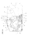
- a combination meter 1 in which a single or a plurality of analogue meters 2 such as a speedmeter or a tachometer is combined with a liquid crystal display 3 to form a display surface on which various vehicle information is displayed is conventionally known as an automobile meter as illustrated in FIG. 10 (refer to, for example, Patent Document 1).
- the constitution of the combination meter 1 will be hereinafter described.
- the conventional combination meter 1 includes an approximately box-shaped meter housing 5 provided in an instrument panel located in front of a driver's seat in a vehicle interior and an opening for a dial 5a concaved on the vehicle interior side.
- a display surface member 4 constituting the plate-like display surface is mounted on the opening for a dial 5a.
- An opening for a liquid crystal display 4a is formed in the approximately central portion of the lower portion of the display surface member 4 in the vehicle width direction.
- the liquid crystal display 3 from which a liquid crystal display surface 3a is exposed is provided in the opening for a liquid crystal display 4a to be visible from the vehicle interior direction.
- the liquid crystal display surface 3a of the liquid crystal display 3 of the combination meter 1 is formed in a rectangular shape in which its longitudinal direction conforms to the vehicle width direction.
- a pair of dials 2a, 2a of the analogue meters 2, 2 such as tachometers is provided to the right and left in the upper portion of the display surface member 4 provided with the liquid crystal display 3. Facing outer rim portions 2c, 2c of the analogue meters 2, 2 include therebetween a predetermined measurement W1.
- a common light-guiding member 6 is provided on the back sides of the liquid crystal display surface 3a and the dials 2a, 2a of the display surface member 4.
- the light-guiding member 6 is configured to transmit illumination light by a transparent member, and includes on the back side thereof a triangular groove 6a which adjusts illumination light from a backlight LED light source 3b built in the liquid crystal display 3 and illumination light from a backlight source 2b of the analogue meter device 2.
- the illumination light from the backlight source 2b of the analogue meter device 2 guided from the side through the light-guiding member 6 disposed on the back side of the dial 2a is reflected by the triangular groove 6a in the direction of the bottom face of the meter housing 5.
- Patent Document 1 Japanese Patent Application Publication No. 2005-24526 (paragraphs 0020-0111, FIG. 1 ) .
- the liquid crystal display 3 is provided between the analogue meters 2, 2, and the facing outer rim portions 2c, 2c of the analogue meters 2, 2 are overlapped with the right and left lateral edge portions of the case of the liquid crystal display 3 so as to increase a displayable area of the dials 2a, 2a of the analogue meter devices 2, 2.
- the width W2 between the right and left lateral edge portions of the case of the liquid crystal display 3 is larger than the width W1 between the outer rim portions 2c, 2c of the analogue meters 2, 2.
- the illumination light of the backlight sources 2b, 2b does not reach the outer rim portions 2c, 2c of the analogue meter devices 2, 2 in the overlapped portions due to the shade of the right and left lateral edge portions, so that illumination unevenness occurs due to a difference in the light volume from the circumferential portion. Because of this, the external appearance quality may be deteriorated.
- an object of the present invention to provide a meter in which an outer appearance quality is improved by even backlight illumination.
- a meter of an embodiment of the present invention includes a liquid crystal display having a liquid crystal display surface and a case housing the liquid crystal display surface, an analogue meter device including a dial portion having a plurality of translucent indicators, a light source configured to illuminate the dial portion from a back side of the dial portion, and an illumination light-passing section formed in a lateral edge portion of the case, configured to pass light from the light source toward the translucent indicator.
- FIGs. 1-9 a meter of an embodiment of the present invention will be described with reference to FIGs. 1-9 .
- a combination meter 10 of a display device for a vehicle is provided in an instrument panel 9 located in front of a driver' s seat 8b in a passenger compartment 8a of an automobile 8 as illustrated in FIG. 6 as the meter of the embodiment.
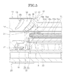
- the combination meter 10 includes an approximately box-shaped meter housing 5 having a dial opening 5a which opens toward the driver's seat 8b, a speedmeter 12 and a tachometer 13 as analogue meters accommodated in the meter housing 5, a liquid crystal display 11 having a liquid crystal display surface 11a which displays various vehicle information and a plate-like dial member 14 and a molded graduated-dial member 15 as a dial portion constituting a part of the display surface, which are located in front of the speedmeter 12 and the tachometer 13 and close the dial opening 5a, as illustrated in FIG. 1
- a circuit substrate 16 having a plurality of LEDs 17 as backlight sources is provided in the meter housing 5 as illustrated in FIG. 3 .
- the plate-like dial member 14 and the molded graduated-dial member 15 are illuminated from the back side by the illumination light of the LEDs 17.
- the liquid crystal display 11 is disposed between the speedmeter 12 and the tachometer 13 as illustrated in FIG. 1 .
- the liquid crystal display surface 11a is disposed in an opening for a liquid crystal display 14a formed in the approximately central portion of the plate-like dial member 14 in the vehicle width direction.
- An opening 15a is provided between a pair of circular rings 15b, 15c integrally formed with the molded graduated-dial member 15 as a part of the dial plate.
- a resin LCD case member 20 is provided in the peripheral portion of the liquid crystal display surface 11a.
- the LCD case member 20 includes an LCD upper case 18 and an LCD lower case 19 which is fitted to the LCD upper case 18.
- the liquid crystal display surface 11a, an LCD glass member 11b and the like are housed in the LCD upper and lower cases 18, 19.
- the LCD upper case 18 includes an approximately rectangular window 18a in which its longitudinal direction conforms to the vehicle up-and-down direction in accordance with the opening for the liquid crystal display 14a.
- a non-printed translucent rim portion 14b formed in the peripheral portion of the opening for the liquid crystal display 14a of the plate-like dial member 14 and rim portions on a liquid crystal display side 15d, 15e as a part of the circular rings 15b, 15c are attached to case lateral edge portions 18b, 18c facing each other in the substantially vehicle width direction.
- the case lateral edge portions 18b, 18c, the translucent rim portion 14b and the rim portions on the liquid crystal display side 15d, 15e are overlapped.
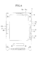
- a long slit 21 as an illumination light-passing section having a cutout corner shape is formed in the case lateral edge portion 18b of the LCD upper case 18 of this embodiment.
- the longitudinal direction of the long slit 21 conforms to the direction to which the side of the LCD upper case 18 extends.
- the long slit 21 penetrates the case lateral edge portion 18b in the inside and outside direction of the liquid crystal display surface 11a, and extends in the vehicle width direction of the liquid crystal display surface 11a.
- the long slit 21 includes an approximately L-shape in section.
- connection frame 18f In this embodiment, upper and lower frames 18d, 18e of the case lateral edge portion 18b separated by the opening space of the long slit 21 are connected by a connection frame 18f.
- a short slit 22 as an illumination light-passing section having a cutout corner shape is formed in the case lateral edge portion 18c of the LCD upper case 18.
- the longitudinal direction of the short slit 22 conforms to the direction to which the side of the LCD upper case 18 extends.
- the short slit 22 penetrates the case lateral edge portion 18b in the inside and outside direction of the liquid crystal display surface 11a, and extends in the vehicle width direction of the liquid crystal display surface 11a.
- the short slit 22 includes an approximately L-shape in section.
- upper and lower frames 18g, 18h of the case lateral edge portion 18c separated by a plurality of opening spaces of the short slits 22 are connected by connection frames 18i.
- a plurality of reinforcing ribs 18j is formed along the vehicle width direction between the connection frames 18i and the remaining portions of the case lateral edge portion 18c at predetermined intervals in the up and down direction of the vehicle in the case lateral edge portion 18c.
- ring sections 23, 23 schematically defining the contours of the speedmeter 12 and the tachometer 13 in appearances are formed in the outermost rims of the circular rings 15b, 15c in the diameter direction, respectively, by metal decoration printing as non-translucent portions.
- the liquid crystal display 11 is combined with the speedmeter 12 and the tachometer 13, such that the ring sections 23, 23 of the non-translucent portions of the circular rings 15b, 15c are overlapped with the connection frame 18f, 18i in a front view of the combination meter 10, and the outer circumferential portion of the dial is overlapped with a portion which is not backlight-illuminated
- a red zone scale portion 15h as a scale portion indicating rev-limit is provided in the rim portion on the liquid crystal display side 15d of the circular ring 15b in accordance with the position of the long slit 21.
- the red zone scale portion 15h includes in the circumferential direction at equal intervals small scales 15f and large scales 15i, which are illuminated by the illumination light of the LEDs 17 from the back side, and transmit a part or the entire illumination light in the vehicle interior direction, as a plurality of translucent indicators.
- a speed display scale portion 15k as a scale portion is provided in the rim portion on the liquid crystal display side 15e of the circular ring 15c in accordance with the positions of the short slits 22.
- the speed display scale portion 15k includes in the circumferential direction at equal intervals a plurality of large scales 15i, intermediate scales 15j and small scales 15g, which are illuminated by the illumination light of the LEDs 17 from the back side, and transmit a part or the entire illumination light in the vehicle interior direction.
- the inside edges of the long slit 21 and the short slits 22 are located in circular virtual lines 23a, 23a connecting the outer edge portions of the speed display scale portion 15k and the red zone scale portion 15h.
- the circular virtual lines 23a, 23a connecting the outer edge portions of the scales conform to the inner rims of the ring sections 23, 23, respectively, as illustrated in FIG. 4 .
- top portions of the circular virtual lines 23a, 23a conform to the inside edges of the window 18a in the vehicle width direction as illustrated in FIG. 4 .
- Each of the large scales 15i, intermediate scales 15j and small scales 15g are irradiated by the illumination light of the LEDs 17 because each of the scales is located between the reinforcing ribs 18j, 18j .
- a plurality of large scales 15i, intermediate scales 15j and small scales 15g in the speedmeter 12 of this embodiment is illustrated in the same figure as illustrated in FIG. 4 . However, they are appropriately used depending on a case in which a speed is displayed in km/h or mile/h.
- the illumination light by the lighting of the LEDs 17, 17 is irradiated to the corner portions of the case lateral edge portions 18b, 18c of the liquid crystal display 11 in the vehicle width direction from the back side of the plate-like dial member 14 of each of the speedmeter 12 and the tachometer 13.
- the illumination light of the respective LEDs 17, 17 passes through the long and short slits 21, 22 each having a cutout corner shape.
- the illumination light of the LEDs 17, 17 which has passed through the long and short slits 21, 22 passes through the translucent rim portions 14b, 14b of the plate-like dial member 14, and illuminates the portion of each circular ring 15b, 15c of the molded graduated-dial member 15, which is overlapped with the case lateral edge portion 18b, 18c.
- the circular rings 15b, 15c are backlight-illuminated similar to the other portions, so that it becomes possible to reduce the illumination unevenness with the circumferential portion.
- the circular rings 15b, 15c are overlapped with the case lateral edge portions 18b, 18c as illustrated in FIGs. 1 , 4 .
- the display portions of the dial portion for use in the displays of the speedmeter 12 and the tachometer 13 are able to be located closer to the liquid crystal display surface 11a for use in the display of the liquid crystal display 11.
- the external appearance quality is also improved due to the even backlight illumination.
- connection frames 18f, 18i the shade is overlapped with the ring sections 23, 23 provided in the circular rings 15b, 15c of the speedmeter 12 and the tachometer 13, so as to prevent illumination unevenness.
- the ring sections 23, 23 of the circular rings 15b, 15c are overlapped with the connection frames 18f, 18i formed in the case lateral edge portions 18b, 18c, respectively, in the vehicle width direction.
- each of the speedmeter 12 and the tachometer 13 is combined with the liquid crystal display device 11.
- the portions of the circular rings 15b, 15c over the case lateral edge portions 18b, 18c which are not used as display surfaces in the conventional constitution can be effectively used as the luminous red zone scale portion 15h and speed display scale portion 15k even if the tops of the circular virtual lines 23a, 23a connecting the outer edge portions of the respective scales of the speedmeter 12 and the tachometer 13 are located closer to each other in the vehicle width direction.
- the display area of the limited display portion of the combination meter 10 can be effectively used.
- the long slit 21 is consecutively formed in the extending direction of the red zone scale portion 15h which is formed in the circular ring 15b and is provided with a plurality of small scales 15f.
- the plurality of small scales 15f is backlight-illuminated with an even light volume even if a plurality of equally formed small scales 15f of the red zone scale portion 15h is arranged at small intervals.
- FIG. 5 is a view illustrating a combination meter 30 as a meter of Embodiment 1 of the present invention.
- a crimp portion 34 as an asperity is formed on a back face 33 of an inclined surface portion 32 provided with a scale portion 15I including a plurality of large scales 15i in a circular ring 31 corresponding to the circular ring 15b of the embodiment.
- the crimp portion 34 formed in the back face 33 of the inclined surface portion 32 provided with the scale portion 15I diffuses the illumination light of the LEDs 17 to obtain even backlight illumination due to the diffusion.
- the illumination unevenness reduced by the long slit 21 is further diffused by the crimp portion 34, so that the light volume difference can be reduced due to the diffusion. Therefore, the outer appearance quality of the circular ring 31 can be further improved.
- the individually provided plate-like dial member 14 and the molded graduated-dial member 15 are combined as the dial portion constituting a part of the display surface in the embodiment.
- the constitution is not limited thereto.
- a decoration ring can be integrally formed with a plate-like dial.
- the shape of the display surface, number, material and colors of the meters and warning lights are not especially limited.
- the illumination light passes through the illumination passing section having a cutout corner shape even if the illumination light is irradiated toward the corner portions of the case lateral edge portions of the liquid crystal display from the back side.
- the portions overlapped with the corner portions of the case lateral edge portions, for example, the scale portion and the like are backlight-illuminated by the illumination light from the backlight source, which has passed through the illumination light-passing section, and thus, illumination unevenness with the circumferential portion can be reduced.
- This constitution makes it possible to maintain a preferable external appearance quality and to effectively use the display area of the display even if the virtual lines connecting the outer edge portions of the translucent indicators are closely arranged such that the outer circumferential portions of the scale portions, for example as the non-translucent portions are overlapped with the connection frames formed in the case lateral edge portions.
- the dial portion for use in the display of the analogue meter and the liquid crystal display surface for use in the display of the liquid crystal display are closely positioned, so that the displayable area of the dial portion can be expanded in the limited display surface of the meter.
- the external appearance quality can be improved due to the even backlight illumination while improving the layout freedom and effectively using the display area.
- the meter as constituted above includes the asperity formed in the dial portion. This asperity diffuses the illumination light.
- This constitution makes it possible to further reduce the illumination unevenness reduced by the illumination light-passing section due to the diffusion, so that a preferable external appearance quality can be obtained.
- the meter as constituted above includes the consecutive illumination light-passing section formed in the extending direction of the scale portion formed in the dial portion.
- a part of the translucent indicator formed in the dial portion is disposed to overlap with the case member.
- the dial portion can be disposed not to overlap with the case member.
- the illumination light-passing section can be formed in the portion forming the shadow of the case member. Namely, if a part of the case member is inserted on the optical path from the light source to the translucent indicator, the illumination light-passing section can be formed in the inserted portion.
Landscapes
- Engineering & Computer Science (AREA)
- Chemical & Material Sciences (AREA)
- Combustion & Propulsion (AREA)
- Transportation (AREA)
- Mechanical Engineering (AREA)
- Physics & Mathematics (AREA)
- General Physics & Mathematics (AREA)
- Details Of Measuring Devices (AREA)
- Instrument Panels (AREA)
Abstract
Description
- The present invention relates to a meter for use in a vehicle such as an automobile. In particular, the present invention relates to a combination meter in which an analogue meter is disposed adjacent to a liquid crystal display.
- A
combination meter 1 in which a single or a plurality ofanalogue meters 2 such as a speedmeter or a tachometer is combined with aliquid crystal display 3 to form a display surface on which various vehicle information is displayed is conventionally known as an automobile meter as illustrated inFIG. 10 (refer to, for example, Patent Document 1). - The constitution of the
combination meter 1 will be hereinafter described. Theconventional combination meter 1 includes an approximately box-shaped meter housing 5 provided in an instrument panel located in front of a driver's seat in a vehicle interior and an opening for adial 5a concaved on the vehicle interior side. - A display surface member 4 constituting the plate-like display surface is mounted on the opening for a
dial 5a. - An opening for a
liquid crystal display 4a is formed in the approximately central portion of the lower portion of the display surface member 4 in the vehicle width direction. Theliquid crystal display 3 from which a liquidcrystal display surface 3a is exposed is provided in the opening for aliquid crystal display 4a to be visible from the vehicle interior direction. - The liquid
crystal display surface 3a of theliquid crystal display 3 of thecombination meter 1 is formed in a rectangular shape in which its longitudinal direction conforms to the vehicle width direction. A pair ofdials analogue meters liquid crystal display 3. Facingouter rim portions analogue meters - A common light-guiding
member 6 is provided on the back sides of the liquidcrystal display surface 3a and thedials - The light-guiding
member 6 is configured to transmit illumination light by a transparent member, and includes on the back side thereof a triangular groove 6a which adjusts illumination light from a backlightLED light source 3b built in theliquid crystal display 3 and illumination light from abacklight source 2b of theanalogue meter device 2. - Next, the operation and effect of the conventional meter will be described.
- The illumination light from the
backlight source 2b of theanalogue meter device 2 guided from the side through the light-guidingmember 6 disposed on the back side of thedial 2a is reflected by the triangular groove 6a in the direction of the bottom face of themeter housing 5. - For this reason, a light volume and an illumination shape of the
liquid crystal display 3 and theanalogue meters 2 close to a desired light volume and a desired illumination shape are obtained even if the light-guidingmember 6 for performing the backlight illumination of theliquid crystal display 3 and theanalogue meters - Patent Document 1: Japanese Patent Application Publication No.
2005-24526 FIG. 1 ) . - In the conventional meter constituted as described above, as illustrated by the two-dot chain line in the figure, the
liquid crystal display 3 is provided between theanalogue meters outer rim portions analogue meters liquid crystal display 3 so as to increase a displayable area of thedials analogue meter devices liquid crystal display 3 is larger than the width W1 between theouter rim portions analogue meters - However, the illumination light of the
backlight sources outer rim portions analogue meter devices - It is, therefore, an object of the present invention to provide a meter in which an outer appearance quality is improved by even backlight illumination.
- In order to achieve the above object, a meter of an embodiment of the present invention includes a liquid crystal display having a liquid crystal display surface and a case housing the liquid crystal display surface, an analogue meter device including a dial portion having a plurality of translucent indicators, a light source configured to illuminate the dial portion from a back side of the dial portion, and an illumination light-passing section formed in a lateral edge portion of the case, configured to pass light from the light source toward the translucent indicator.
-
-
FIG. 1 is a front view illustrating one example of a layout of a combination meter as a meter of an embodiment of the present invention. -
FIG. 2 is a sectional view along A-A line inFIG. 1 illustrating an inside constitution of the combination meter as the meter of the embodiment of the present invention. -
FIG. 3 is an enlarged sectional view of B section inFIG. 2 illustrating the meter of the embodiment of the present invention. -
FIG. 4 is an enlarged sectional view of C section inFIG. 1 illustrating the meter of the embodiment of the present invention. -
FIG. 5 is an enlarged sectional view of a position along D-D line inFIG. 4 illustrating a meter ofEmbodiment 1 of the present invention. -
FIG. 6 is a side view of a vehicle and a front view of a vehicle interior illustrating the arrangement of the combination meter as the meter of the embodiment of the present invention. -
FIG. 7 is a left side view illustrating a constitution of a case member of a liquid crystal display in the meter of the embodiment of the present invention. -
FIG. 8 is a front view illustrating the constitution of the case member of the liquid crystal display in the meter of the embodiment of the present invention. -
FIG. 9 is a right side view illustrating the constitution of the case member of the liquid crystal display in the meter of the embodiment of the present invention. -
FIG. 10 is a front view illustrating a constitution of a combination meter with a transparent cover member removed as a conventional meter. - Hereinafter, a meter of an embodiment of the present invention will be described with reference to
FIGs. 1-9 . - First of all, the constitution of the meter is described. A
combination meter 10 of a display device for a vehicle is provided in an instrument panel 9 located in front of a driver' sseat 8b in apassenger compartment 8a of anautomobile 8 as illustrated inFIG. 6 as the meter of the embodiment. - The
combination meter 10 includes an approximately box-shaped meter housing 5 having a dial opening 5a which opens toward the driver'sseat 8b, aspeedmeter 12 and atachometer 13 as analogue meters accommodated in themeter housing 5, aliquid crystal display 11 having a liquidcrystal display surface 11a which displays various vehicle information and a plate-like dial member 14 and a molded graduated-dial member 15 as a dial portion constituting a part of the display surface, which are located in front of thespeedmeter 12 and thetachometer 13 and close the dial opening 5a, as illustrated inFIG. 1 - A
circuit substrate 16 having a plurality ofLEDs 17 as backlight sources is provided in themeter housing 5 as illustrated inFIG. 3 . The plate-like dial member 14 and the molded graduated-dial member 15 are illuminated from the back side by the illumination light of theLEDs 17. - The
liquid crystal display 11 is disposed between thespeedmeter 12 and thetachometer 13 as illustrated inFIG. 1 . The liquidcrystal display surface 11a is disposed in an opening for aliquid crystal display 14a formed in the approximately central portion of the plate-like dial member 14 in the vehicle width direction. An opening 15a is provided between a pair ofcircular rings dial member 15 as a part of the dial plate. - Various vehicle information displayed on the liquid
crystal display surface 11a is visible from the vehicle interior direction through the opening for theliquid crystal display 14a and the opening 15a between rings. - A resin
LCD case member 20 is provided in the peripheral portion of the liquidcrystal display surface 11a. TheLCD case member 20 includes an LCDupper case 18 and an LCDlower case 19 which is fitted to the LCDupper case 18. The liquidcrystal display surface 11a, anLCD glass member 11b and the like are housed in the LCD upper andlower cases - The LCD
upper case 18 includes an approximatelyrectangular window 18a in which its longitudinal direction conforms to the vehicle up-and-down direction in accordance with the opening for theliquid crystal display 14a. As illustrated inFIG. 3 , a non-printedtranslucent rim portion 14b formed in the peripheral portion of the opening for theliquid crystal display 14a of the plate-like dial member 14 and rim portions on a liquidcrystal display side circular rings lateral edge portions lateral edge portions translucent rim portion 14b and the rim portions on the liquidcrystal display side - In addition, the
translucent rim portion 14b of the plate-like dial member 14 is omitted inFIG. 4 for simplifying the description. - As illustrated in
FIGs. 7 ,8 , along slit 21 as an illumination light-passing section having a cutout corner shape is formed in the caselateral edge portion 18b of the LCDupper case 18 of this embodiment. The longitudinal direction of thelong slit 21 conforms to the direction to which the side of the LCDupper case 18 extends. Thelong slit 21 penetrates the caselateral edge portion 18b in the inside and outside direction of the liquidcrystal display surface 11a, and extends in the vehicle width direction of the liquidcrystal display surface 11a. Thelong slit 21 includes an approximately L-shape in section. - In this embodiment, upper and
lower frames lateral edge portion 18b separated by the opening space of thelong slit 21 are connected by aconnection frame 18f. - As illustrated in
FIGs. 8 .9 , ashort slit 22 as an illumination light-passing section having a cutout corner shape is formed in the caselateral edge portion 18c of the LCDupper case 18. The longitudinal direction of theshort slit 22 conforms to the direction to which the side of the LCDupper case 18 extends. Theshort slit 22 penetrates the caselateral edge portion 18b in the inside and outside direction of the liquidcrystal display surface 11a, and extends in the vehicle width direction of the liquidcrystal display surface 11a. Theshort slit 22 includes an approximately L-shape in section. - In this embodiment, upper and
lower frames lateral edge portion 18c separated by a plurality of opening spaces of theshort slits 22 are connected byconnection frames 18i. - A plurality of reinforcing
ribs 18j is formed along the vehicle width direction between the connection frames 18i and the remaining portions of the caselateral edge portion 18c at predetermined intervals in the up and down direction of the vehicle in the caselateral edge portion 18c. - In this embodiment,
ring sections speedmeter 12 and thetachometer 13 in appearances are formed in the outermost rims of thecircular rings - The
liquid crystal display 11 is combined with thespeedmeter 12 and thetachometer 13, such that thering sections circular rings connection frame combination meter 10, and the outer circumferential portion of the dial is overlapped with a portion which is not backlight-illuminated - As illustrated in
FIG. 4 , a redzone scale portion 15h as a scale portion indicating rev-limit is provided in the rim portion on the liquidcrystal display side 15d of thecircular ring 15b in accordance with the position of thelong slit 21. The redzone scale portion 15h includes in the circumferential direction at equal intervalssmall scales 15f andlarge scales 15i, which are illuminated by the illumination light of theLEDs 17 from the back side, and transmit a part or the entire illumination light in the vehicle interior direction, as a plurality of translucent indicators. - A speed
display scale portion 15k as a scale portion is provided in the rim portion on the liquidcrystal display side 15e of thecircular ring 15c in accordance with the positions of theshort slits 22. The speeddisplay scale portion 15k includes in the circumferential direction at equal intervals a plurality oflarge scales 15i,intermediate scales 15j andsmall scales 15g, which are illuminated by the illumination light of theLEDs 17 from the back side, and transmit a part or the entire illumination light in the vehicle interior direction. - The inside edges of the
long slit 21 and theshort slits 22 are located in circularvirtual lines display scale portion 15k and the redzone scale portion 15h. - In this embodiment, the circular
virtual lines ring sections FIG. 4 . - The top portions of the circular
virtual lines window 18a in the vehicle width direction as illustrated inFIG. 4 . - For this reason, most of the outer circumferential portions of the scales connected by the circular virtual lines overlap with the connection frames 18f, 18i.
- Each of the
large scales 15i,intermediate scales 15j andsmall scales 15g are irradiated by the illumination light of theLEDs 17 because each of the scales is located between the reinforcingribs - A plurality of
large scales 15i,intermediate scales 15j andsmall scales 15g in thespeedmeter 12 of this embodiment is illustrated in the same figure as illustrated inFIG. 4 . However, they are appropriately used depending on a case in which a speed is displayed in km/h or mile/h. - Next, the operation and effect of the meter of this embodiment will be described.
- In the meter of the embodiment as constituted above, the illumination light by the lighting of the
LEDs lateral edge portions liquid crystal display 11 in the vehicle width direction from the back side of the plate-like dial member 14 of each of thespeedmeter 12 and thetachometer 13. - The illumination light of the
respective LEDs short slits - The illumination light of the
LEDs short slits translucent rim portions like dial member 14, and illuminates the portion of eachcircular ring dial member 15, which is overlapped with the caselateral edge portion - Therefore, the
circular rings - In the
combination meter 10 described in the present embodiment, thecircular rings lateral edge portions FIGs. 1 ,4 . With this constitution, the display portions of the dial portion for use in the displays of thespeedmeter 12 and thetachometer 13 are able to be located closer to the liquidcrystal display surface 11a for use in the display of theliquid crystal display 11. - For this reason, it becomes possible to increase the displayable area of the dial portion in the limited display surface of the
combination meter 10 illustrated inFIG. 1 , so that the layout freedom can be improved and, in addition, the display area can be effectively used. - The external appearance quality is also improved due to the even backlight illumination.
- More specifically, although a part of the illumination light which has reached the corner portions of the case
lateral edge portions LEDs ring sections circular rings speedmeter 12 and thetachometer 13, so as to prevent illumination unevenness. - In the display portion of the
combination meter 10 illustrated inFIG. 4 , thering sections circular rings lateral edge portions speedmeter 12 and thetachometer 13 is combined with the liquidcrystal display device 11. - Therefore, the portions of the
circular rings lateral edge portions zone scale portion 15h and speeddisplay scale portion 15k even if the tops of the circularvirtual lines speedmeter 12 and thetachometer 13 are located closer to each other in the vehicle width direction. Thus, the display area of the limited display portion of thecombination meter 10 can be effectively used. - In this embodiment, the
long slit 21 is consecutively formed in the extending direction of the redzone scale portion 15h which is formed in thecircular ring 15b and is provided with a plurality ofsmall scales 15f. - With this constitution, the plurality of
small scales 15f is backlight-illuminated with an even light volume even if a plurality of equally formedsmall scales 15f of the redzone scale portion 15h is arranged at small intervals. - Thus, a preferable external appearance quality can be obtained without generating illumination unevenness in the circumferential direction of the
circular ring 15b. -
FIG. 5 is a view illustrating acombination meter 30 as a meter ofEmbodiment 1 of the present invention. - In addition, the same reference numbers are applied to the same portions in the above-described embodiment.
- First of all, the constitutional difference is mainly described. In the
combination meter 30 ofEmbodiment 1, acrimp portion 34 as an asperity is formed on aback face 33 of aninclined surface portion 32 provided with a scale portion 15I including a plurality oflarge scales 15i in acircular ring 31 corresponding to thecircular ring 15b of the embodiment. - Next, the operation and effect of the meter of
Embodiment 1 will be described. - In the
combination meter 30 ofEmbodiment 1 as constituted above, thecrimp portion 34 formed in theback face 33 of theinclined surface portion 32 provided with the scale portion 15I diffuses the illumination light of theLEDs 17 to obtain even backlight illumination due to the diffusion. - In
Embodiment 1, the illumination unevenness reduced by thelong slit 21 is further diffused by thecrimp portion 34, so that the light volume difference can be reduced due to the diffusion. Therefore, the outer appearance quality of thecircular ring 31 can be further improved. - The other constitutions and the operation and effect are the same as those of the meter in the above-described embodiment. Thus, the description thereof will be omitted.
- The meters according to the embodiment and
Embodiment 1 are described in detail above with reference to the drawings. However, the specific constitution is not limited to thecombination meters Embodiment 1. It should be appreciated that variations may be made in the embodiment andEmbodiment 1 described by persons skilled in the art without departing from the scope of the present invention. - For example, the individually provided plate-
like dial member 14 and the molded graduated-dial member 15 are combined as the dial portion constituting a part of the display surface in the embodiment. However, the constitution is not limited thereto. For example, a decoration ring can be integrally formed with a plate-like dial. The shape of the display surface, number, material and colors of the meters and warning lights are not especially limited. - According to the meter as constituted above, the illumination light passes through the illumination passing section having a cutout corner shape even if the illumination light is irradiated toward the corner portions of the case lateral edge portions of the liquid crystal display from the back side.
- With this constitution, the portions overlapped with the corner portions of the case lateral edge portions, for example, the scale portion and the like are backlight-illuminated by the illumination light from the backlight source, which has passed through the illumination light-passing section, and thus, illumination unevenness with the circumferential portion can be reduced.
- Moreover, even if the illumination light from the backlight source is blocked by the connection frames, illumination unevenness does not occur because the shade is overlapped with the non-translucent portion of the dial portion.
- This constitution makes it possible to maintain a preferable external appearance quality and to effectively use the display area of the display even if the virtual lines connecting the outer edge portions of the translucent indicators are closely arranged such that the outer circumferential portions of the scale portions, for example as the non-translucent portions are overlapped with the connection frames formed in the case lateral edge portions.
- Therefore, the dial portion for use in the display of the analogue meter and the liquid crystal display surface for use in the display of the liquid crystal display are closely positioned, so that the displayable area of the dial portion can be expanded in the limited display surface of the meter.
- Thus, the external appearance quality can be improved due to the even backlight illumination while improving the layout freedom and effectively using the display area.
- The meter as constituted above includes the asperity formed in the dial portion. This asperity diffuses the illumination light.
- This constitution makes it possible to further reduce the illumination unevenness reduced by the illumination light-passing section due to the diffusion, so that a preferable external appearance quality can be obtained.
- The meter as constituted above includes the consecutive illumination light-passing section formed in the extending direction of the scale portion formed in the dial portion.
- With this constitution, a plurality of scales of the scale portion is backlight-illuminated with an even light volume. Thus, a preferable external appearance quality can be obtained without generating illumination unevenness.
In the present embodiment, a part of the translucent indicator formed in the dial portion is disposed to overlap with the case member. However, the dial portion can be disposed not to overlap with the case member.
In this case, if a part of the translucent indicator of the dial portion becomes the shadow of the light from the light source by the case member, the illumination light-passing section can be formed in the portion forming the shadow of the case member.
Namely, if a part of the case member is inserted on the optical path from the light source to the translucent indicator, the illumination light-passing section can be formed in the inserted portion.
The present application is based on and claims priority from Japanese Patent Application No.2009-254720, filed on November 6, 2009
Claims (7)
- A meter, comprising:a liquid crystal display having a liquid crystal display surface and a case housing the liquid crystal display surface;an analogue meter including a dial portion having a plurality of translucent indicators;a light source configured to illuminate the dial portion from a back side of the dial portion; andan illumination light-passing section formed in a lateral edge portion of the case, configured to pass light from the light source toward the translucent indicators.
- The meter according to Claim 1, wherein the illumination light-passing section is a cutout formed in the lateral edge portion of the case.
- The meter according to Claim 2, wherein the case includes a connection frame connecting portions remaining in the lateral edge portion of the case due to the formation of the cutout.
- The meter according to Claim 3, wherein the dial portion includes a non-translucent portion, and the non-translucent portion is disposed to overlap with the connection frame.
- The meter according to Claim 1, wherein the illumination light-passing section is disposed close to a virtual line connecting the outer edge portions of the translucent indicators.
- The meter according to Claim 1, wherein the dial portion includes an asperity configured to diffuse the light from the light source.
- The meter according to Claim 2, wherein the dial portion includes a scale portion in which a plurality of scales made of transmissive slits is equally formed in a circumferential direction, and the illumination light-passing section made of consecutive cutouts is provided in an extending direction of the scale portion.
Applications Claiming Priority (2)
| Application Number | Priority Date | Filing Date | Title |
|---|---|---|---|
| JP2009254720A JP5431121B2 (en) | 2009-11-06 | 2009-11-06 | Meter lighting structure |
| PCT/JP2010/068802 WO2011055646A1 (en) | 2009-11-06 | 2010-10-25 | Meter |
Publications (3)
| Publication Number | Publication Date |
|---|---|
| EP2498068A1 true EP2498068A1 (en) | 2012-09-12 |
| EP2498068A4 EP2498068A4 (en) | 2015-01-07 |
| EP2498068B1 EP2498068B1 (en) | 2017-12-20 |
Family
ID=43969886
Family Applications (1)
| Application Number | Title | Priority Date | Filing Date |
|---|---|---|---|
| EP10828206.2A Active EP2498068B1 (en) | 2009-11-06 | 2010-10-25 | Meter |
Country Status (5)
| Country | Link |
|---|---|
| US (1) | US9302585B2 (en) |
| EP (1) | EP2498068B1 (en) |
| JP (1) | JP5431121B2 (en) |
| CN (1) | CN102597712B (en) |
| WO (1) | WO2011055646A1 (en) |
Families Citing this family (12)
| Publication number | Priority date | Publication date | Assignee | Title |
|---|---|---|---|---|
| JP5971700B2 (en) * | 2012-05-17 | 2016-08-17 | アルパイン株式会社 | Display device |
| JP5962719B2 (en) * | 2013-09-17 | 2016-08-03 | 株式会社デンソー | Vehicle display device |
| DE102014201885A1 (en) * | 2014-02-03 | 2015-08-06 | Johnson Controls Automotive Electronics Gmbh | Cover for at least one display instrument in a vehicle |
| JP6202013B2 (en) * | 2015-02-05 | 2017-09-27 | マツダ株式会社 | Vehicle display device |
| JP6508610B2 (en) * | 2015-02-12 | 2019-05-08 | 中国電力株式会社 | Current detector |
| JP6400185B2 (en) * | 2015-04-06 | 2018-10-03 | カルソニックカンセイ株式会社 | Vehicle display device |
| JP6308172B2 (en) | 2015-06-11 | 2018-04-11 | 株式会社デンソー | Display device |
| USD820753S1 (en) * | 2016-03-01 | 2018-06-19 | Bentley Motors Ltd. | Automobile dashboard assembly |
| USD799389S1 (en) * | 2016-03-01 | 2017-10-10 | Bentley Motors Limited | Automobile dashboard display |
| JP6959812B2 (en) * | 2017-09-25 | 2021-11-05 | 日本精機株式会社 | Vehicle display device |
| USD1031474S1 (en) * | 2022-05-26 | 2024-06-18 | Brunswick Corporation | Gauge faceplate |
| USD1031473S1 (en) * | 2022-05-26 | 2024-06-18 | Brunswick Corporation | Gauge faceplate |
Family Cites Families (22)
| Publication number | Priority date | Publication date | Assignee | Title |
|---|---|---|---|---|
| US5915822A (en) * | 1996-08-09 | 1999-06-29 | Kansei Corporation | Meter with light transmitting board |
| DE19857862A1 (en) * | 1998-12-15 | 2000-06-29 | Mannesmann Vdo Ag | Display unit |
| JP4208316B2 (en) * | 1999-01-11 | 2009-01-14 | 株式会社デンソー | Illumination structure of meter device |
| JP4734743B2 (en) * | 2001-03-30 | 2011-07-27 | 株式会社デンソー | Vehicle instrument |
| JP2002347460A (en) | 2001-05-24 | 2002-12-04 | Toyo Tire & Rubber Co Ltd | Control lever |
| JP2002357460A (en) * | 2001-05-31 | 2002-12-13 | Nippon Seiki Co Ltd | Measuring instrument |
| JP4310952B2 (en) | 2001-09-28 | 2009-08-12 | 日本精機株式会社 | Pointer type display device |
| JP4287627B2 (en) * | 2002-07-30 | 2009-07-01 | 日本精機株式会社 | Pointer-type instrument |
| JP4073800B2 (en) * | 2003-02-12 | 2008-04-09 | カルソニックカンセイ株式会社 | Vehicle instrumentation |
| JP2005024526A (en) | 2003-06-10 | 2005-01-27 | Calsonic Kansei Corp | Meter illumination structure |
| JP2005024306A (en) * | 2003-06-30 | 2005-01-27 | Nippon Seiki Co Ltd | Instrument device |
| EP1724556B1 (en) * | 2004-03-09 | 2011-07-06 | Denso Corporation | Display device for vehicle |
| FR2871229B1 (en) * | 2004-06-04 | 2006-09-01 | Johnson Controls Tech Co | INDICATOR DEVICE WITH LED NEEDLE |
| JP2006194613A (en) * | 2005-01-11 | 2006-07-27 | Calsonic Kansei Corp | On-vehicle measuring device |
| JP4894371B2 (en) | 2005-09-22 | 2012-03-14 | 株式会社デンソー | Vehicle display device |
| JP4650210B2 (en) | 2005-10-27 | 2011-03-16 | 株式会社デンソー | Vehicle indicator instrument |
| US7675428B2 (en) * | 2007-01-19 | 2010-03-09 | Denso International America, Inc. | Rotating gauge pointer and light guide between LCD and LED |
| JP5481780B2 (en) * | 2007-11-27 | 2014-04-23 | 日本精機株式会社 | Indicating instrument |
| JP2009151251A (en) * | 2007-12-24 | 2009-07-09 | Denso Corp | Display device |
| JP2009254720A (en) | 2008-04-21 | 2009-11-05 | Fukuo Otani | Washbowl |
| JP5196310B2 (en) * | 2008-08-28 | 2013-05-15 | 日本精機株式会社 | Pointer-type instrument |
| JP5116645B2 (en) * | 2008-11-28 | 2013-01-09 | カルソニックカンセイ株式会社 | Vehicle display device |
-
2009
- 2009-11-06 JP JP2009254720A patent/JP5431121B2/en active Active
-
2010
- 2010-10-25 US US13/505,807 patent/US9302585B2/en active Active
- 2010-10-25 CN CN201080049451.4A patent/CN102597712B/en active Active
- 2010-10-25 WO PCT/JP2010/068802 patent/WO2011055646A1/en not_active Ceased
- 2010-10-25 EP EP10828206.2A patent/EP2498068B1/en active Active
Also Published As
| Publication number | Publication date |
|---|---|
| US9302585B2 (en) | 2016-04-05 |
| WO2011055646A1 (en) | 2011-05-12 |
| EP2498068A4 (en) | 2015-01-07 |
| CN102597712B (en) | 2015-12-02 |
| CN102597712A (en) | 2012-07-18 |
| JP2011099760A (en) | 2011-05-19 |
| US20120218493A1 (en) | 2012-08-30 |
| EP2498068B1 (en) | 2017-12-20 |
| JP5431121B2 (en) | 2014-03-05 |
Similar Documents
| Publication | Publication Date | Title |
|---|---|---|
| EP2498068B1 (en) | Meter | |
| JP6491532B2 (en) | Vehicle display device | |
| JP5642631B2 (en) | Instrument lighting device | |
| EP3045342A1 (en) | Reconfigurable gauge over display | |
| JP6798266B2 (en) | Display device | |
| JP2006194613A (en) | On-vehicle measuring device | |
| JP2013088351A (en) | Meter device | |
| JP6456697B2 (en) | Vehicle display device | |
| KR101162356B1 (en) | prism gradation of instrument panel for automobile | |
| WO2018221205A1 (en) | Instrument | |
| JP5134491B2 (en) | Instrument device | |
| JP4330888B2 (en) | Vehicle display device | |
| JP4652787B2 (en) | Display device | |
| JP5767902B2 (en) | Vehicle instrument | |
| JP4895332B2 (en) | Pointer type display device | |
| JP6056244B2 (en) | Pointer-type instrument device | |
| CN101334300A (en) | Instrumentation | |
| JP2018040625A (en) | Vehicle display device | |
| JP5310601B2 (en) | Vehicle display device | |
| JP2011226838A (en) | Measuring apparatus for vehicle | |
| JPH10240176A (en) | Display device | |
| JP2021189032A (en) | Display device | |
| JP2020003321A (en) | Display device | |
| JP2013044673A (en) | Vehicle meter | |
| JP2019082453A (en) | Display |
Legal Events
| Date | Code | Title | Description |
|---|---|---|---|
| PUAI | Public reference made under article 153(3) epc to a published international application that has entered the european phase |
Free format text: ORIGINAL CODE: 0009012 |
|
| 17P | Request for examination filed |
Effective date: 20120525 |
|
| AK | Designated contracting states |
Kind code of ref document: A1 Designated state(s): AL AT BE BG CH CY CZ DE DK EE ES FI FR GB GR HR HU IE IS IT LI LT LU LV MC MK MT NL NO PL PT RO RS SE SI SK SM TR |
|
| DAX | Request for extension of the european patent (deleted) | ||
| A4 | Supplementary search report drawn up and despatched |
Effective date: 20141204 |
|
| RIC1 | Information provided on ipc code assigned before grant |
Ipc: B60K 35/00 20060101ALI20141128BHEP Ipc: G01D 11/28 20060101AFI20141128BHEP |
|
| RIC1 | Information provided on ipc code assigned before grant |
Ipc: B60K 35/00 20060101ALI20170510BHEP Ipc: B60K 37/02 20060101ALI20170510BHEP Ipc: G01D 11/28 20060101AFI20170510BHEP |
|
| GRAP | Despatch of communication of intention to grant a patent |
Free format text: ORIGINAL CODE: EPIDOSNIGR1 |
|
| STAA | Information on the status of an ep patent application or granted ep patent |
Free format text: STATUS: GRANT OF PATENT IS INTENDED |
|
| INTG | Intention to grant announced |
Effective date: 20170718 |
|
| GRAS | Grant fee paid |
Free format text: ORIGINAL CODE: EPIDOSNIGR3 |
|
| GRAA | (expected) grant |
Free format text: ORIGINAL CODE: 0009210 |
|
| STAA | Information on the status of an ep patent application or granted ep patent |
Free format text: STATUS: THE PATENT HAS BEEN GRANTED |
|
| AK | Designated contracting states |
Kind code of ref document: B1 Designated state(s): AL AT BE BG CH CY CZ DE DK EE ES FI FR GB GR HR HU IE IS IT LI LT LU LV MC MK MT NL NO PL PT RO RS SE SI SK SM TR |
|
| REG | Reference to a national code |
Ref country code: GB Ref legal event code: FG4D |
|
| REG | Reference to a national code |
Ref country code: CH Ref legal event code: EP |
|
| REG | Reference to a national code |
Ref country code: IE Ref legal event code: FG4D |
|
| REG | Reference to a national code |
Ref country code: AT Ref legal event code: REF Ref document number: 956790 Country of ref document: AT Kind code of ref document: T Effective date: 20180115 |
|
| REG | Reference to a national code |
Ref country code: DE Ref legal event code: R096 Ref document number: 602010047561 Country of ref document: DE |
|
| REG | Reference to a national code |
Ref country code: NL Ref legal event code: MP Effective date: 20171220 |
|
| PG25 | Lapsed in a contracting state [announced via postgrant information from national office to epo] |
Ref country code: FI Free format text: LAPSE BECAUSE OF FAILURE TO SUBMIT A TRANSLATION OF THE DESCRIPTION OR TO PAY THE FEE WITHIN THE PRESCRIBED TIME-LIMIT Effective date: 20171220 Ref country code: LT Free format text: LAPSE BECAUSE OF FAILURE TO SUBMIT A TRANSLATION OF THE DESCRIPTION OR TO PAY THE FEE WITHIN THE PRESCRIBED TIME-LIMIT Effective date: 20171220 Ref country code: NO Free format text: LAPSE BECAUSE OF FAILURE TO SUBMIT A TRANSLATION OF THE DESCRIPTION OR TO PAY THE FEE WITHIN THE PRESCRIBED TIME-LIMIT Effective date: 20180320 Ref country code: SE Free format text: LAPSE BECAUSE OF FAILURE TO SUBMIT A TRANSLATION OF THE DESCRIPTION OR TO PAY THE FEE WITHIN THE PRESCRIBED TIME-LIMIT Effective date: 20171220 |
|
| REG | Reference to a national code |
Ref country code: LT Ref legal event code: MG4D |
|
| REG | Reference to a national code |
Ref country code: AT Ref legal event code: MK05 Ref document number: 956790 Country of ref document: AT Kind code of ref document: T Effective date: 20171220 |
|
| PG25 | Lapsed in a contracting state [announced via postgrant information from national office to epo] |
Ref country code: HR Free format text: LAPSE BECAUSE OF FAILURE TO SUBMIT A TRANSLATION OF THE DESCRIPTION OR TO PAY THE FEE WITHIN THE PRESCRIBED TIME-LIMIT Effective date: 20171220 Ref country code: GR Free format text: LAPSE BECAUSE OF FAILURE TO SUBMIT A TRANSLATION OF THE DESCRIPTION OR TO PAY THE FEE WITHIN THE PRESCRIBED TIME-LIMIT Effective date: 20180321 Ref country code: LV Free format text: LAPSE BECAUSE OF FAILURE TO SUBMIT A TRANSLATION OF THE DESCRIPTION OR TO PAY THE FEE WITHIN THE PRESCRIBED TIME-LIMIT Effective date: 20171220 Ref country code: RS Free format text: LAPSE BECAUSE OF FAILURE TO SUBMIT A TRANSLATION OF THE DESCRIPTION OR TO PAY THE FEE WITHIN THE PRESCRIBED TIME-LIMIT Effective date: 20171220 Ref country code: BG Free format text: LAPSE BECAUSE OF FAILURE TO SUBMIT A TRANSLATION OF THE DESCRIPTION OR TO PAY THE FEE WITHIN THE PRESCRIBED TIME-LIMIT Effective date: 20180320 |
|
| PG25 | Lapsed in a contracting state [announced via postgrant information from national office to epo] |
Ref country code: NL Free format text: LAPSE BECAUSE OF FAILURE TO SUBMIT A TRANSLATION OF THE DESCRIPTION OR TO PAY THE FEE WITHIN THE PRESCRIBED TIME-LIMIT Effective date: 20171220 |
|
| PG25 | Lapsed in a contracting state [announced via postgrant information from national office to epo] |
Ref country code: ES Free format text: LAPSE BECAUSE OF FAILURE TO SUBMIT A TRANSLATION OF THE DESCRIPTION OR TO PAY THE FEE WITHIN THE PRESCRIBED TIME-LIMIT Effective date: 20171220 Ref country code: CZ Free format text: LAPSE BECAUSE OF FAILURE TO SUBMIT A TRANSLATION OF THE DESCRIPTION OR TO PAY THE FEE WITHIN THE PRESCRIBED TIME-LIMIT Effective date: 20171220 Ref country code: CY Free format text: LAPSE BECAUSE OF FAILURE TO SUBMIT A TRANSLATION OF THE DESCRIPTION OR TO PAY THE FEE WITHIN THE PRESCRIBED TIME-LIMIT Effective date: 20171220 Ref country code: EE Free format text: LAPSE BECAUSE OF FAILURE TO SUBMIT A TRANSLATION OF THE DESCRIPTION OR TO PAY THE FEE WITHIN THE PRESCRIBED TIME-LIMIT Effective date: 20171220 Ref country code: SK Free format text: LAPSE BECAUSE OF FAILURE TO SUBMIT A TRANSLATION OF THE DESCRIPTION OR TO PAY THE FEE WITHIN THE PRESCRIBED TIME-LIMIT Effective date: 20171220 |
|
| PG25 | Lapsed in a contracting state [announced via postgrant information from national office to epo] |
Ref country code: IT Free format text: LAPSE BECAUSE OF FAILURE TO SUBMIT A TRANSLATION OF THE DESCRIPTION OR TO PAY THE FEE WITHIN THE PRESCRIBED TIME-LIMIT Effective date: 20171220 Ref country code: IS Free format text: LAPSE BECAUSE OF FAILURE TO SUBMIT A TRANSLATION OF THE DESCRIPTION OR TO PAY THE FEE WITHIN THE PRESCRIBED TIME-LIMIT Effective date: 20180420 Ref country code: RO Free format text: LAPSE BECAUSE OF FAILURE TO SUBMIT A TRANSLATION OF THE DESCRIPTION OR TO PAY THE FEE WITHIN THE PRESCRIBED TIME-LIMIT Effective date: 20171220 Ref country code: PL Free format text: LAPSE BECAUSE OF FAILURE TO SUBMIT A TRANSLATION OF THE DESCRIPTION OR TO PAY THE FEE WITHIN THE PRESCRIBED TIME-LIMIT Effective date: 20171220 Ref country code: AT Free format text: LAPSE BECAUSE OF FAILURE TO SUBMIT A TRANSLATION OF THE DESCRIPTION OR TO PAY THE FEE WITHIN THE PRESCRIBED TIME-LIMIT Effective date: 20171220 Ref country code: SM Free format text: LAPSE BECAUSE OF FAILURE TO SUBMIT A TRANSLATION OF THE DESCRIPTION OR TO PAY THE FEE WITHIN THE PRESCRIBED TIME-LIMIT Effective date: 20171220 |
|
| REG | Reference to a national code |
Ref country code: FR Ref legal event code: PLFP Year of fee payment: 9 |
|
| REG | Reference to a national code |
Ref country code: DE Ref legal event code: R097 Ref document number: 602010047561 Country of ref document: DE |
|
| PLBE | No opposition filed within time limit |
Free format text: ORIGINAL CODE: 0009261 |
|
| STAA | Information on the status of an ep patent application or granted ep patent |
Free format text: STATUS: NO OPPOSITION FILED WITHIN TIME LIMIT |
|
| 26N | No opposition filed |
Effective date: 20180921 |
|
| PG25 | Lapsed in a contracting state [announced via postgrant information from national office to epo] |
Ref country code: DK Free format text: LAPSE BECAUSE OF FAILURE TO SUBMIT A TRANSLATION OF THE DESCRIPTION OR TO PAY THE FEE WITHIN THE PRESCRIBED TIME-LIMIT Effective date: 20171220 |
|
| PG25 | Lapsed in a contracting state [announced via postgrant information from national office to epo] |
Ref country code: SI Free format text: LAPSE BECAUSE OF FAILURE TO SUBMIT A TRANSLATION OF THE DESCRIPTION OR TO PAY THE FEE WITHIN THE PRESCRIBED TIME-LIMIT Effective date: 20171220 |
|
| REG | Reference to a national code |
Ref country code: CH Ref legal event code: PL |
|
| REG | Reference to a national code |
Ref country code: BE Ref legal event code: MM Effective date: 20181031 |
|
| PG25 | Lapsed in a contracting state [announced via postgrant information from national office to epo] |
Ref country code: LU Free format text: LAPSE BECAUSE OF NON-PAYMENT OF DUE FEES Effective date: 20181025 Ref country code: MC Free format text: LAPSE BECAUSE OF FAILURE TO SUBMIT A TRANSLATION OF THE DESCRIPTION OR TO PAY THE FEE WITHIN THE PRESCRIBED TIME-LIMIT Effective date: 20171220 |
|
| REG | Reference to a national code |
Ref country code: IE Ref legal event code: MM4A |
|
| PG25 | Lapsed in a contracting state [announced via postgrant information from national office to epo] |
Ref country code: LI Free format text: LAPSE BECAUSE OF NON-PAYMENT OF DUE FEES Effective date: 20181031 Ref country code: BE Free format text: LAPSE BECAUSE OF NON-PAYMENT OF DUE FEES Effective date: 20181031 Ref country code: CH Free format text: LAPSE BECAUSE OF NON-PAYMENT OF DUE FEES Effective date: 20181031 |
|
| PG25 | Lapsed in a contracting state [announced via postgrant information from national office to epo] |
Ref country code: IE Free format text: LAPSE BECAUSE OF NON-PAYMENT OF DUE FEES Effective date: 20181025 |
|
| PG25 | Lapsed in a contracting state [announced via postgrant information from national office to epo] |
Ref country code: MT Free format text: LAPSE BECAUSE OF NON-PAYMENT OF DUE FEES Effective date: 20181025 |
|
| PG25 | Lapsed in a contracting state [announced via postgrant information from national office to epo] |
Ref country code: TR Free format text: LAPSE BECAUSE OF FAILURE TO SUBMIT A TRANSLATION OF THE DESCRIPTION OR TO PAY THE FEE WITHIN THE PRESCRIBED TIME-LIMIT Effective date: 20171220 |
|
| PG25 | Lapsed in a contracting state [announced via postgrant information from national office to epo] |
Ref country code: PT Free format text: LAPSE BECAUSE OF FAILURE TO SUBMIT A TRANSLATION OF THE DESCRIPTION OR TO PAY THE FEE WITHIN THE PRESCRIBED TIME-LIMIT Effective date: 20171220 |
|
| PG25 | Lapsed in a contracting state [announced via postgrant information from national office to epo] |
Ref country code: HU Free format text: LAPSE BECAUSE OF FAILURE TO SUBMIT A TRANSLATION OF THE DESCRIPTION OR TO PAY THE FEE WITHIN THE PRESCRIBED TIME-LIMIT; INVALID AB INITIO Effective date: 20101025 Ref country code: MK Free format text: LAPSE BECAUSE OF NON-PAYMENT OF DUE FEES Effective date: 20171220 |
|
| PG25 | Lapsed in a contracting state [announced via postgrant information from national office to epo] |
Ref country code: AL Free format text: LAPSE BECAUSE OF FAILURE TO SUBMIT A TRANSLATION OF THE DESCRIPTION OR TO PAY THE FEE WITHIN THE PRESCRIBED TIME-LIMIT Effective date: 20171220 |
|
| PGFP | Annual fee paid to national office [announced via postgrant information from national office to epo] |
Ref country code: GB Payment date: 20250923 Year of fee payment: 16 |
|
| PGFP | Annual fee paid to national office [announced via postgrant information from national office to epo] |
Ref country code: FR Payment date: 20250924 Year of fee payment: 16 |
|
| PGFP | Annual fee paid to national office [announced via postgrant information from national office to epo] |
Ref country code: DE Payment date: 20250923 Year of fee payment: 16 |