EP2498030A2 - Motor-driven ice dispenser for refrigerators - Google Patents
Motor-driven ice dispenser for refrigerators Download PDFInfo
- Publication number
- EP2498030A2 EP2498030A2 EP10795191A EP10795191A EP2498030A2 EP 2498030 A2 EP2498030 A2 EP 2498030A2 EP 10795191 A EP10795191 A EP 10795191A EP 10795191 A EP10795191 A EP 10795191A EP 2498030 A2 EP2498030 A2 EP 2498030A2
- Authority
- EP
- European Patent Office
- Prior art keywords
- door
- electric motor
- opening
- refrigerators
- motor
- Prior art date
- Legal status (The legal status is an assumption and is not a legal conclusion. Google has not performed a legal analysis and makes no representation as to the accuracy of the status listed.)
- Withdrawn
Links
- 239000011295 pitch Substances 0.000 claims description 23
- 230000033001 locomotion Effects 0.000 claims description 15
- 239000011521 glass Substances 0.000 description 7
- 230000004913 activation Effects 0.000 description 6
- 230000007246 mechanism Effects 0.000 description 4
- 230000009467 reduction Effects 0.000 description 4
- 239000003570 air Substances 0.000 description 3
- 239000012080 ambient air Substances 0.000 description 3
- 230000008901 benefit Effects 0.000 description 3
- 238000000034 method Methods 0.000 description 3
- 239000000047 product Substances 0.000 description 3
- 238000007789 sealing Methods 0.000 description 3
- 238000005457 optimization Methods 0.000 description 2
- 238000004804 winding Methods 0.000 description 2
- 230000004931 aggregating effect Effects 0.000 description 1
- 239000007795 chemical reaction product Substances 0.000 description 1
- 238000010276 construction Methods 0.000 description 1
- 230000003247 decreasing effect Effects 0.000 description 1
- 230000005672 electromagnetic field Effects 0.000 description 1
- 239000011810 insulating material Substances 0.000 description 1
- 239000000463 material Substances 0.000 description 1
- 230000008569 process Effects 0.000 description 1
- 239000002699 waste material Substances 0.000 description 1
Images

Classifications
-
- F—MECHANICAL ENGINEERING; LIGHTING; HEATING; WEAPONS; BLASTING
- F25—REFRIGERATION OR COOLING; COMBINED HEATING AND REFRIGERATION SYSTEMS; HEAT PUMP SYSTEMS; MANUFACTURE OR STORAGE OF ICE; LIQUEFACTION SOLIDIFICATION OF GASES
- F25C—PRODUCING, WORKING OR HANDLING ICE
- F25C5/00—Working or handling ice
- F25C5/20—Distributing ice
- F25C5/22—Distributing ice particularly adapted for household refrigerators
-
- H—ELECTRICITY
- H02—GENERATION; CONVERSION OR DISTRIBUTION OF ELECTRIC POWER
- H02P—CONTROL OR REGULATION OF ELECTRIC MOTORS, ELECTRIC GENERATORS OR DYNAMO-ELECTRIC CONVERTERS; CONTROLLING TRANSFORMERS, REACTORS OR CHOKE COILS
- H02P25/00—Arrangements or methods for the control of AC motors characterised by the kind of AC motor or by structural details
- H02P25/02—Arrangements or methods for the control of AC motors characterised by the kind of AC motor or by structural details characterised by the kind of motor
- H02P25/022—Synchronous motors
- H02P25/024—Synchronous motors controlled by supply frequency
Definitions
- the present invention relates to a motor ice dispenser for refrigerators, said dispenser being provided with an electric motor with different usage velocities.
- the household electric appliances have been aggregating various facilities due to the technological advance, to the manufacturers constant innovation process and to the costumers' requirements.
- the ice dispensers in refrigerators and fridges. These dispensers provide ice in the form of cubes or other forms as appropriate, without the costumer having to open the fridge door, as is the case with traditional refrigerators or fridges.
- the fridge apart from its major function of storing food, increasing its life, possesses a facility that distinguishes it and makes it unique.
- these dispensers have an activation element that serves to open a door, through which the ice falls.
- This activation element is normally a kind of extended arm, and, when the costumer presses said arm with a glass, for example, a piece of ice falls into the glass via the door opening. Said door prevents the ambient air from contacting the air inside the refrigerator, avoiding the unnecessary transfer of heat and moisture.
- the dispensers comprise solenoids or electric motors that perform the opening of the door which releases the piece of ice.
- the dispensers provided with solenoid have a plurality of drawbacks, the main ones being: the noise generated when the dispenser is being used and the high consumption of electric power.
- multiple solutions have been presented aiming at the replacement of the solenoid by a device capable of performing the same functions, but with a lower power waste.
- an ice dispenser comprising a pitch motor, more precisely a bipolar, full-pitch permanent magnet pitch motor.
- a pitch motor more precisely a bipolar, full-pitch permanent magnet pitch motor.
- two coils are activated (or turned on) at the same time, so that the rotor will have 90 ⁇ pitches and its magnetic poles will be located between the coils.
- the advantage of the dispenser over the ones previously mentioned is that the pitch motor provides more precisely for the control of the door position without a hardware and software complex implementation.
- the dispensers using a pitch motor usually have the door joined to its shaft, such that the rotation of the motor shaft is directly transformed into the rotation of the door, without the need for using intermediate elements (e.g., gears).
- an ice dispenser for fridges and/or refrigerators must exist that comprises a simple mechanism and, at the same time, a motor spending little power.
- this dispenser it is still desirable for this dispenser to have low cost, through the optimization of its mechanism and related devices.
- an ice dispenser for refrigerators comprising: a door that seals the refrigerator inner environment to the environment external to the refrigerator, the door being able to release pieces of ice upon its opening; an electric motor operatively connected to the door, the electric motor being responsible for said door opening motion.
- the electric motor is able to start the door opening at a low speed and high torque and to end the door opening at a high speed and low torque.
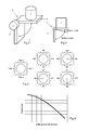
- Figure 1 - illustrates the windings and the sequence of motions of the motor used in the state of the art dispensers
- Figure 2 - illustrates in a schematic manner the behavior of the magnetic field in a permanent magnet pitch motor of the bipolar, full-pitch type, used in state of the art ice dispensers;
- Figure 3 - illustrates a schematic perspective view of the preferred embodiment of the present invention
- Figure 4 - illustrates a schematic side view of the preferred embodiment of the present invention
- Figure 5 illustrates the windings and the sequence of motions of the pitch motor used in the present invention.
- Figure 6 - illustrates a curve that represents the general behavior of the torque resulting from the speed in pitch motors.
- the ice dispenser of the present invention is schematically represented in Figures 3 and 4 .
- some parts of the dispenser are omitted since the aim is to show in an easily understandable way the most relevant elements for the present invention.
- the ice dispenser of the present invention is preferably used in refrigerators and similar devices, that is, in refrigerators, freezers, fridges, among others. Other applications, however, must be considered, provided that they are covered by the protection scope of the appended claims.
- the ice dispenser of the present invention preferably has a space for the costumer to put a glass or another similar receiver, in order to add pieces of ice to the inside of said receiver or glass.
- the ice dispenser of the present invention may be located in any region of the refrigerator door, or even next to its side surfaces, but this feature should not limit the scope of the present invention.
- the piece of ice 2 can be made available to the costumer by means of the driving of a lever, through a button or through an arm that may be pushed by a glass that the costumer is using.
- the important feature of this driving means is that it must be in electric connection with electric motor 3, so that its actuation activates motor 3 and, as a consequence, opens door 1 for the release of piece of ice 2.
- the dispenser of the present invention comprises a door 1, already mentioned, the function of which is to seal the refrigerator inner environment to the refrigerator outer environment.
- door 1 is the interface between the ambient air and the air inside the refrigerator and it must have sealing means, since the ambient air may interfere on the air moisture from the refrigerator inside.
- Any applicable sealing means may be used in the dispenser of the present invention, from polymeric materials to even the use of door 1 dimensions relative to the opening through which piece of ice 2 is made available to the customer.
- door 1 is substantially "L" shaped or has the form of a "half-cross". This shape consists of two parallelepiped projections having a vertex in common, with a 90 ⁇ spacing between them. Also, the present invention contemplates the use of a door having 3 projections that share the same vertex and are spaced about 120 ⁇ from one another.
- door 1 may take on various forms, without its functionality in the context of the present invention being harmed because of this.
- the relevant feature that door 1 must comprise is a point in common to all projections, that is, a vertex in common from which the projections originate, since they are the projections that will effectively perform the function of sealing the refrigerator inner environment to the environment external to the refrigerator.
- the ice dispenser of the present invention comprises an electric motor 3 responsible for door 1 opening motion.
- This electric motor 3 is preferably a pitch motor, desirably a permanent magnet, unipolar and full-pitch motor.
- Electric motor 3 is further operatively connected to door 1, that is, the shaft of electric motor 3 is coupled to the vertex common to projections 4.
- electric motor 3 has the motion of its shaft directly transmitted to door 1, without the need for a mechanical system for transmitting this motion, as is the case with the subject matter of document US 2006/0201193 .
- FIG. 5 illustrates the sequence of motions by motor 3.
- the coils of electric motor 3 stator and the direction of the rotor north pole are schematically represented.
- a single coil 5 is activated, or energized, at one time.
- the state of the art embodiment illustrated in Figure 1 uses a pitch motor that activates two coils at a time, which, as has already been said, leads to a higher power consumption.
- the present invention has thus the advantage of spending little power through the activation of a single coil at a time.
- this higher torque can be used when door 1 starts being closed to assure that the inertia is overcome more easily.
- a control system drives and sends pulses to electric motor 3, entailing the rotation of its shaft, which implies the rotation of door 1.
- the opening begins, that is, to take door 1 from rest, the torque resulting from the motion of electric motor 3 shaft is higher, its velocity being lower. After a predetermined period, the torque becomes lower, and its velocity higher, thus ending the opening motion.
- the opening motion encompasses preferably 90 ⁇ and, after ended, the costumer will have a piece of ice 2 in his glass or another receiver.
- the control system of the present invention is preferably a system that drives and turns off the motor, in addition to controlling the velocities adopted by the motor during the opening and the closing of door 1 of the present invention dispenser. Still preferably, this control system comprises a microcontroller or a microprocessor associated with a circuit for directly driving (“driver"), since many microcontrollers and microprocessors do not have power enough for directly driving one of its output pins.
- driver directly driving
- electric motor 3 in the portion at the beginning of door 1 opening, operates at 50 PPS (pulses per second), performing 100 pitches and having a torque that may reach 0,300 Nm. In the portion at the end of door 1 opening, electric motor 3 operates a 800 PPS, performing 700 pitches and having a torque that may reach 0,200 Nm.
- PPS pulse per second
- electric motor 3 operates a 800 PPS, performing 700 pitches and having a torque that may reach 0,200 Nm.
- the value, in degrees, corresponding to the start of door 1 opening and the end of the door opening, is varied according to the other values (velocity, torque and the number of pulses per second), and, for each combination of values, there is an arch corresponding to the motion in the beginning and the end of the door opening.
- the arches shown in Figure 4 which correspond to the beginning and the end of the opening, are merely illustrative and intend to represent the concept of the present invention.
- the present invention uses an electric motor 3 that activates a coil at a time, rather than two coils as is the case with state of the art dispensers, a substantial power saving is provided. Also, the torque compensation by choosing two velocity modes for opening door 1 (beginning and end) results in an optimization of the usage of electric motor 3 as a source of power saving, as compared with the state of the art examples. It should be remembered that the reduction in the consumption of power is directly related to the cost reduction, which is one more benefit brought about by the present invention.
- the dispenser of the present invention can be considered as a low power product, that is, a product that spends less than 15 W of power in its operation.
- the dispenser of the present invention spends an average power of 4,6 W.
Landscapes
- Engineering & Computer Science (AREA)
- Physics & Mathematics (AREA)
- Mechanical Engineering (AREA)
- Thermal Sciences (AREA)
- General Engineering & Computer Science (AREA)
- Refrigerator Housings (AREA)
- Control Of Electric Motors In General (AREA)
- Power-Operated Mechanisms For Wings (AREA)
Abstract
The present invention relates to a motor ice dispenser for refrigerators comprising an electric motor (3) programmed to have two operating velocities during the opening of a door (1), for the release of a piece of ice (2) for the costumer. In the beginning of the door (1) opening, the electric motor (3) operates at a low speed and high torque, and, at the end of the door (1) opening, the electric motor (3) operates at a high speed and low torque.
Description
- Field of the Invention
- The present invention relates to a motor ice dispenser for refrigerators, said dispenser being provided with an electric motor with different usage velocities.
- Background of the Invention
- The household electric appliances have been aggregating various facilities due to the technological advance, to the manufacturers constant innovation process and to the costumers' requirements. Among the multiple existing examples, one can point out the ice dispensers in refrigerators and fridges. These dispensers provide ice in the form of cubes or other forms as appropriate, without the costumer having to open the fridge door, as is the case with traditional refrigerators or fridges. Thus, the fridge, apart from its major function of storing food, increasing its life, possesses a facility that distinguishes it and makes it unique.
- Normally, these dispensers have an activation element that serves to open a door, through which the ice falls. This activation element is normally a kind of extended arm, and, when the costumer presses said arm with a glass, for example, a piece of ice falls into the glass via the door opening. Said door prevents the ambient air from contacting the air inside the refrigerator, avoiding the unnecessary transfer of heat and moisture.
- As far as the technical details for providing said dispensers are concerned, the state of the art has several examples. In most cases, the dispensers comprise solenoids or electric motors that perform the opening of the door which releases the piece of ice.
- The dispensers provided with solenoid have a plurality of drawbacks, the main ones being: the noise generated when the dispenser is being used and the high consumption of electric power. In this aspect, multiple solutions have been presented aiming at the replacement of the solenoid by a device capable of performing the same functions, but with a lower power waste.
- One of the solutions aiming at the replacement of the solenoid is found in document
US 2007/0256442 , which describes a motor ice dispenser door comprising a shaft coupled to said door, a motor coupled to said shaft and an resilient element associated with the door. In this manner, the motor turns the shaft, and the latter turns the door, opening it. The resilient element, which, in the preferred embodiment described in this US document, is a spring, has the function of keeping the door closed. The motor is driven through an electric switch, which may be a button or another appropriate device. The motor used is an asynchronous alternating current motor. - Another example of the state of the art for the replacement of the solenoid in ice dispensers is found in document
US 2006/0201193 . According to the description of this document, when the user presses an arm with a glass or another similar object, an electric motor is driven causing a small gear arranged in its shaft to turn. Thus, a shaft connected with said gear also turns, causing a second gear to turn as well. This second gear is operatively connected to the door that releases the ice cube. Thus, the subject matter of this document of the state of the art makes use of the association of gear and shafts to open the door and make the piece of ice available to the user. - These two examples mentioned have the disadvantage of using a relatively complex mechanical apparatus. In this sense, an ice dispenser has been developed comprising a pitch motor, more precisely a bipolar, full-pitch permanent magnet pitch motor. Thus, as can be seen in
Figure 1 , two coils are activated (or turned on) at the same time, so that the rotor will have 90□ pitches and its magnetic poles will be located between the coils. The advantage of the dispenser over the ones previously mentioned is that the pitch motor provides more precisely for the control of the door position without a hardware and software complex implementation. - In addition, the use of a bipolar, full-pitch pitch motor is particular advantageous having in mind that the activation of two coils simultaneously increases the torque, since the resulting magnetic field will be the sum of the electromagnetic fields of each coil.
Figure 2 illustrates this behavior of the magnetic field and the electric current. - The dispensers using a pitch motor usually have the door joined to its shaft, such that the rotation of the motor shaft is directly transformed into the rotation of the door, without the need for using intermediate elements (e.g., gears).
- Although the use of the pitch motor represents an advance over the other examples of the state of the art mentioned, its use still has a considerable disadvantage, that is: high power consumption. This disadvantage entails other disadvantages since the high power consumption is directly converted into a cost increase, related to the need for using large power supplies. Also, this excessive power consumption causes the dispenser not to be rated as a low power product for some applications. As such, the dispenser needs to pass tests in order to be approved, which increases its cost, apart from the fact that, in some cases, the dispenser has to incorporate specific insulating materials which also increase the cost of the end product.
- As such, an ice dispenser for fridges and/or refrigerators must exist that comprises a simple mechanism and, at the same time, a motor spending little power. In addition to these features, it is still desirable for this dispenser to have low cost, through the optimization of its mechanism and related devices.
- Obj ects of the Invention
- With the state of the art problems in mind, it is an object of this invention to provide an ice dispenser for refrigerators that comprises both a simple and a low cost door opening mechanism.
- Summary of the Invention
- The objects of this invention are achieved through an ice dispenser for refrigerators comprising: a door that seals the refrigerator inner environment to the environment external to the refrigerator, the door being able to release pieces of ice upon its opening; an electric motor operatively connected to the door, the electric motor being responsible for said door opening motion.
- The electric motor is able to start the door opening at a low speed and high torque and to end the door opening at a high speed and low torque.
- Brief Description of the Drawings
- The figures show:
-
Figure 1 - illustrates the windings and the sequence of motions of the motor used in the state of the art dispensers; -
Figure 2 - illustrates in a schematic manner the behavior of the magnetic field in a permanent magnet pitch motor of the bipolar, full-pitch type, used in state of the art ice dispensers; -
Figure 3 - illustrates a schematic perspective view of the preferred embodiment of the present invention; -
Figure 4 - illustrates a schematic side view of the preferred embodiment of the present invention; -
Figure 5 - illustrates the windings and the sequence of motions of the pitch motor used in the present invention; and -
Figure 6 - illustrates a curve that represents the general behavior of the torque resulting from the speed in pitch motors. - Detailed Description of the Invention
- The ice dispenser of the present invention is schematically represented in
Figures 3 and 4 . In these figures, some parts of the dispenser are omitted since the aim is to show in an easily understandable way the most relevant elements for the present invention. - The ice dispenser of the present invention is preferably used in refrigerators and similar devices, that is, in refrigerators, freezers, fridges, among others. Other applications, however, must be considered, provided that they are covered by the protection scope of the appended claims.
- As well as the state of the art dispensers, the ice dispenser of the present invention preferably has a space for the costumer to put a glass or another similar receiver, in order to add pieces of ice to the inside of said receiver or glass. In addition, the ice dispenser of the present invention may be located in any region of the refrigerator door, or even next to its side surfaces, but this feature should not limit the scope of the present invention.
- Regarding the driving means of this dispenser, the most varied mechanisms may be used. As such, the piece of
ice 2 can be made available to the costumer by means of the driving of a lever, through a button or through an arm that may be pushed by a glass that the costumer is using. The important feature of this driving means is that it must be in electric connection withelectric motor 3, so that its actuation activatesmotor 3 and, as a consequence, opensdoor 1 for the release of piece ofice 2. - The dispenser of the present invention comprises a
door 1, already mentioned, the function of which is to seal the refrigerator inner environment to the refrigerator outer environment. In other words,door 1 is the interface between the ambient air and the air inside the refrigerator and it must have sealing means, since the ambient air may interfere on the air moisture from the refrigerator inside. Any applicable sealing means may be used in the dispenser of the present invention, from polymeric materials to even the use ofdoor 1 dimensions relative to the opening through which piece ofice 2 is made available to the customer. - As can be seen from
Figures 3 and 4 ,door 1 is substantially "L" shaped or has the form of a "half-cross". This shape consists of two parallelepiped projections having a vertex in common, with a 90□ spacing between them. Also, the present invention contemplates the use of a door having 3 projections that share the same vertex and are spaced about 120□ from one another. - As can be noted,
door 1 may take on various forms, without its functionality in the context of the present invention being harmed because of this. The relevant feature thatdoor 1 must comprise is a point in common to all projections, that is, a vertex in common from which the projections originate, since they are the projections that will effectively perform the function of sealing the refrigerator inner environment to the environment external to the refrigerator. - Still with reference to
Figures 3 and 4 , the ice dispenser of the present invention comprises anelectric motor 3 responsible fordoor 1 opening motion. Thiselectric motor 3 is preferably a pitch motor, desirably a permanent magnet, unipolar and full-pitch motor. -
Electric motor 3 is further operatively connected todoor 1, that is, the shaft ofelectric motor 3 is coupled to the vertex common toprojections 4. Thus,electric motor 3 has the motion of its shaft directly transmitted todoor 1, without the need for a mechanical system for transmitting this motion, as is the case with the subject matter of documentUS 2006/0201193 . - In relation with the operation of
electric motor 3, reference is made toFigure 5 , which illustrates the sequence of motions bymotor 3. InFigure 5 , the coils ofelectric motor 3 stator and the direction of the rotor north pole are schematically represented. As can also be seen, a single coil 5 is activated, or energized, at one time. - On the other hand, the state of the art embodiment illustrated in
Figure 1 uses a pitch motor that activates two coils at a time, which, as has already been said, leads to a higher power consumption. The present invention has thus the advantage of spending little power through the activation of a single coil at a time. However, it must be considered that the activation of only one coil at a time for executing theelectric motor 3 rotation has less torque as compared with the state of the art that uses a pitch motor. - To compensate for this feature of
electric motor 3 construction, the inventors have created a differentiated operation scheme for the opening ofdoor 1 byelectric motor 3. Considering the torque curve resulting from the speed of a pitch motor, as illustrated inFigure 6 , one can note that a reduction in speed, in pulses per second (PPS), implies the increase in the torque. Having this in mind, the inventors have decreased the speed ofelectric motor 3 to opendoor 1. Thus, the loss of torque resulting from the activation of only a coil at a time would be compensated for by the decrease in speed. - However, in order that the opening of the door will not become so slow, causing dissatisfaction in costumers, the inventors have developed the following methodology:
electric motor 3 is programmed to start openingdoor 1 at a high speed and a low torque. This methodology can be more clearly noted through the indications present inFigure 4 . - In addition, it has been observed that a higher torque was only necessary at the beginning of
door 1 opening, since it is at this moment thatelectric motor 3 has to overcome the inertia to perform the motion. Once taken from rest,electric motor 3 can perform the last part ofdoor 1 opening with a reduced torque and at a higher speed. - In an alternative embodiment of the present invention, this higher torque can be used when
door 1 starts being closed to assure that the inertia is overcome more easily. - Briefly, when the costumer drives the electric motor through any driving means (button, arm, switch, lever, etc.), a control system drives and sends pulses to
electric motor 3, entailing the rotation of its shaft, which implies the rotation ofdoor 1. When the opening begins, that is, to takedoor 1 from rest, the torque resulting from the motion ofelectric motor 3 shaft is higher, its velocity being lower. After a predetermined period, the torque becomes lower, and its velocity higher, thus ending the opening motion. The opening motion encompasses preferably 90□ and, after ended, the costumer will have a piece ofice 2 in his glass or another receiver. - The control system of the present invention is preferably a system that drives and turns off the motor, in addition to controlling the velocities adopted by the motor during the opening and the closing of
door 1 of the present invention dispenser. Still preferably, this control system comprises a microcontroller or a microprocessor associated with a circuit for directly driving ("driver"), since many microcontrollers and microprocessors do not have power enough for directly driving one of its output pins. Although the present invention comprises this preferred embodiment, one has to have in mind that other implementation possibilities of a control system to control the dispenser may be used without harming the protection scope of the invention. - In a preferred embodiment, in the portion at the beginning of
door 1 opening,electric motor 3 operates at 50 PPS (pulses per second), performing 100 pitches and having a torque that may reach 0,300 Nm. In the portion at the end ofdoor 1 opening,electric motor 3 operates a 800 PPS, performing 700 pitches and having a torque that may reach 0,200 Nm. The values mentioned are preferable e do not represent any limitation to the protection scope of the present invention, since other values may be used, provided that the essential features of the invention comply with the definitions of the appended claims. - The value, in degrees, corresponding to the start of
door 1 opening and the end of the door opening, is varied according to the other values (velocity, torque and the number of pulses per second), and, for each combination of values, there is an arch corresponding to the motion in the beginning and the end of the door opening. The arches shown inFigure 4 , which correspond to the beginning and the end of the opening, are merely illustrative and intend to represent the concept of the present invention. - Thus, because the present invention uses an
electric motor 3 that activates a coil at a time, rather than two coils as is the case with state of the art dispensers, a substantial power saving is provided. Also, the torque compensation by choosing two velocity modes for opening door 1 (beginning and end) results in an optimization of the usage ofelectric motor 3 as a source of power saving, as compared with the state of the art examples. It should be remembered that the reduction in the consumption of power is directly related to the cost reduction, which is one more benefit brought about by the present invention. - Also, with the reduction in power consumption, the dispenser of the present invention can be considered as a low power product, that is, a product that spends less than 15 W of power in its operation. Preferably, the dispenser of the present invention spends an average power of 4,6 W. Finally, one can note the simple and efficient structure that the dispenser of the present invention has, which can be noted by the direct association in which
electric motor 3 is provided relative todoor 1, without the need for using additional shafts and gears to transmit the motion generated bymotor 3.
Claims (9)
- An ice dispenser for refrigerators, CHARACTERIZED in that it comprises:a door (1) that seals the refrigerator inner environment to the environment external to the refrigerator, the door being able to release pieces of ice (2) upon its opening;at least one electric motor (3) operatively connected to door (1), electric motor (3) being responsible for the opening motion of said door (1),and electric motor (3) being programmed to start the opening of door (1) at a low speed and a high torque and to end the opening of door (1) at a high speed and low torque.
- An ice dispenser for refrigerators, according to claim 1, CHARACTERIZED in that electric motor (3) is a pitch motor.
- An ice dispenser for refrigerators, according to claim 1, CHARACTERIZED in that electric motor (3) is a unipolar full-pitch motor.
- An ice dispenser for refrigerators, according to claims 1 and 2, CHARACTERIZED in that electric motor (3) operates at between 50 and 800 pulses per second from the beginning to the end of the door (1) opening.
- An ice dispenser for refrigerators, according to claims 1 and 2, CHARACTERIZED in that electric motor (3 performs between 100 e 700 pitches from the beginning to the end of the door (1) opening.
- An ice dispenser for refrigerators, according to claims 1 and 2, CHARACTERIZED in that the torque of electric motor (3) during the beginning of the door (1) opening and during the end of the door (1) opening is between 0,200 Nm and 0,300 Nm.
- An ice dispenser for refrigerators, according to claim 1, CHARACTERIZED in that electric motor (3) has the motion of its shaft directly transmitted to door (1).
- An ice dispenser for refrigerators, according to claims 1 and 7, CHARACTERIZED in that door (1) is cross-shaped, the shaft of electric motor (3) coupled to door (1) central point.
- An ice dispenser for refrigerators, according to claims 1 and 4, CHARACTERIZED in that electric motor (3) receives the pulses through a control system.
Applications Claiming Priority (2)
| Application Number | Priority Date | Filing Date | Title |
|---|---|---|---|
| BRPI0904660-7A BRPI0904660A2 (en) | 2009-11-04 | 2009-11-04 | motorized ice dispenser for refrigerators |
| PCT/BR2010/000363 WO2011054070A2 (en) | 2009-11-04 | 2010-11-04 | Motor-driven ice dispenser for refrigerators |
Publications (1)
| Publication Number | Publication Date |
|---|---|
| EP2498030A2 true EP2498030A2 (en) | 2012-09-12 |
Family
ID=43970442
Family Applications (1)
| Application Number | Title | Priority Date | Filing Date |
|---|---|---|---|
| EP10795191A Withdrawn EP2498030A2 (en) | 2009-11-04 | 2010-11-04 | Motor-driven ice dispenser for refrigerators |
Country Status (4)
| Country | Link |
|---|---|
| US (1) | US20120292350A1 (en) |
| EP (1) | EP2498030A2 (en) |
| BR (1) | BRPI0904660A2 (en) |
| WO (1) | WO2011054070A2 (en) |
Families Citing this family (1)
| Publication number | Priority date | Publication date | Assignee | Title |
|---|---|---|---|---|
| KR101932076B1 (en) * | 2012-06-12 | 2018-12-24 | 엘지전자 주식회사 | Refrigerator |
Family Cites Families (18)
| Publication number | Priority date | Publication date | Assignee | Title |
|---|---|---|---|---|
| US1356933A (en) * | 1917-05-31 | 1920-10-26 | Gen Electric | Induction-motor |
| US1362959A (en) * | 1918-11-07 | 1920-12-21 | John B Price | Polyphase induction-motor |
| US1425648A (en) * | 1919-11-03 | 1922-08-15 | Westinghouse Electric & Mfg Co | Motor-control system |
| US4705125A (en) * | 1986-11-14 | 1987-11-10 | Ishida Scales Manufacturing Company, Ltd. | Method of and apparatus for controlling hopper gate motion |
| EP1012952A1 (en) * | 1997-01-29 | 2000-06-28 | Dieter W. Blum | Dynamo-electric machines and control and operating system for the same |
| US6285146B1 (en) * | 1998-08-07 | 2001-09-04 | Nidec America Corporation | Apparatus and method of regulating the speed of a brushless DC motor |
| US6327869B1 (en) * | 1999-10-08 | 2001-12-11 | General Electric Company | Icemaker dose dispenser |
| US6285155B1 (en) * | 1999-10-29 | 2001-09-04 | Abbott Laboratories | Pseudo half-step motor drive method and apparatus |
| JP2001147060A (en) * | 1999-11-18 | 2001-05-29 | Matsushita Refrig Co Ltd | Automatic ice-making machine |
| US6622894B2 (en) * | 2000-02-28 | 2003-09-23 | Anritsu Corporation | Article feeding and discharging device |
| US6563287B2 (en) * | 2000-12-22 | 2003-05-13 | American Standard International Inc. | Method of controlling three phase motor starting sequence |
| GB0324785D0 (en) * | 2003-10-24 | 2003-11-26 | Electronica Products Ltd | Magnetic gearing of permanent magnet brushless motors |
| KR100707347B1 (en) * | 2004-09-30 | 2007-04-13 | 삼성전자주식회사 | Refrigerator |
| US7340914B2 (en) | 2005-01-03 | 2008-03-11 | Whirlpool Corporation | Refrigerator with a water and ice dispenser having a retractable ledge |
| CA2545021A1 (en) * | 2005-05-27 | 2006-11-27 | Maytag Corporation | Refrigerator with improved water and ice dispenser |
| US20080073376A1 (en) * | 2006-04-12 | 2008-03-27 | Imi Cornelius Inc. | Frozen carbonated modulating dispensing valve and/or flavor injection |
| US20070256442A1 (en) | 2006-05-03 | 2007-11-08 | Viking Range Corporation | Motorized ice dispenser door |
| KR100820818B1 (en) * | 2006-11-13 | 2008-04-11 | 엘지전자 주식회사 | Dispensing device and refrigerator using the same |
-
2009
- 2009-11-04 BR BRPI0904660-7A patent/BRPI0904660A2/en not_active IP Right Cessation
-
2010
- 2010-11-04 WO PCT/BR2010/000363 patent/WO2011054070A2/en not_active Ceased
- 2010-11-04 EP EP10795191A patent/EP2498030A2/en not_active Withdrawn
- 2010-11-04 US US13/508,309 patent/US20120292350A1/en not_active Abandoned
Non-Patent Citations (1)
| Title |
|---|
| See references of WO2011054070A2 * |
Also Published As
| Publication number | Publication date |
|---|---|
| WO2011054070A3 (en) | 2011-12-22 |
| BRPI0904660A2 (en) | 2011-11-16 |
| US20120292350A1 (en) | 2012-11-22 |
| WO2011054070A2 (en) | 2011-05-12 |
Similar Documents
| Publication | Publication Date | Title |
|---|---|---|
| TW508426B (en) | Door opening device for storage apparatus | |
| EP2292995B1 (en) | Refrigerator | |
| CN104121748B (en) | Door opener and possess the refrigerator of this door opener | |
| JP6020304B2 (en) | Clutch mechanism | |
| CN208202938U (en) | A kind of acceleration door-opening mechanism and the refrigerator with the mechanism | |
| CN107654583A (en) | A kind of actuator and its method of work of auto-manual electromagnetic sucker type | |
| JP4988483B2 (en) | Pull-out equipment | |
| JP4374380B2 (en) | refrigerator | |
| WO2008052060A2 (en) | Appliance lock using a motor driven linear actuator with helical spring drive | |
| JP4444330B2 (en) | refrigerator | |
| KR20090112362A (en) | Refrigerator | |
| EP2498030A2 (en) | Motor-driven ice dispenser for refrigerators | |
| CN111719985B (en) | Driving mechanism and control method thereof, door body assembly, refrigerator and readable storage medium | |
| CN106762768B (en) | Moulinet structure | |
| US20050017834A1 (en) | Electromechanical stepping switching apparatus having temporally controlled additional functions | |
| JP3716227B2 (en) | Geared motor | |
| WO2008091758A2 (en) | Reversing circuit for ice delivery system | |
| CN109727830A (en) | A kind of circuit breaker operation mechanism driven using electromagnetic vibrator | |
| JP2008190850A (en) | Door opening and closing device | |
| CN218293273U (en) | Hand self-engaging and disengaging gear for electric window opener | |
| JP7474936B2 (en) | refrigerator | |
| CN223318306U (en) | Clutch components, transmission devices, cabinet equipment and refrigerators | |
| JPH0729727Y2 (en) | Reinstatement drive mechanism | |
| KR200411581Y1 (en) | Baffle switch for cold air damper | |
| CN214284461U (en) | Cooking utensil |
Legal Events
| Date | Code | Title | Description |
|---|---|---|---|
| PUAI | Public reference made under article 153(3) epc to a published international application that has entered the european phase |
Free format text: ORIGINAL CODE: 0009012 |
|
| 17P | Request for examination filed |
Effective date: 20120515 |
|
| AK | Designated contracting states |
Kind code of ref document: A2 Designated state(s): AL AT BE BG CH CY CZ DE DK EE ES FI FR GB GR HR HU IE IS IT LI LT LU LV MC MK MT NL NO PL PT RO RS SE SI SK SM TR |
|
| DAX | Request for extension of the european patent (deleted) | ||
| STAA | Information on the status of an ep patent application or granted ep patent |
Free format text: STATUS: THE APPLICATION IS DEEMED TO BE WITHDRAWN |
|
| 18D | Application deemed to be withdrawn |
Effective date: 20180602 |