EP2497972A2 - Sectioned tuning ring for rotating body - Google Patents
Sectioned tuning ring for rotating body Download PDFInfo
- Publication number
- EP2497972A2 EP2497972A2 EP12158324A EP12158324A EP2497972A2 EP 2497972 A2 EP2497972 A2 EP 2497972A2 EP 12158324 A EP12158324 A EP 12158324A EP 12158324 A EP12158324 A EP 12158324A EP 2497972 A2 EP2497972 A2 EP 2497972A2
- Authority
- EP
- European Patent Office
- Prior art keywords
- sectioned
- tuning ring
- tuning
- rotating body
- ring
- Prior art date
- Legal status (The legal status is an assumption and is not a legal conclusion. Google has not performed a legal analysis and makes no representation as to the accuracy of the status listed.)
- Withdrawn
Links
- 230000008878 coupling Effects 0.000 claims abstract description 38
- 238000010168 coupling process Methods 0.000 claims abstract description 38
- 238000005859 coupling reaction Methods 0.000 claims abstract description 38
- 230000013011 mating Effects 0.000 claims description 13
- 238000000034 method Methods 0.000 claims description 12
- 239000000463 material Substances 0.000 description 3
- 238000012986 modification Methods 0.000 description 3
- 230000004048 modification Effects 0.000 description 3
- 238000009434 installation Methods 0.000 description 2
- 238000003754 machining Methods 0.000 description 2
- 238000013459 approach Methods 0.000 description 1
- 230000008901 benefit Effects 0.000 description 1
- 230000008859 change Effects 0.000 description 1
- 230000005520 electrodynamics Effects 0.000 description 1
- 238000005516 engineering process Methods 0.000 description 1
- 238000005259 measurement Methods 0.000 description 1
- 239000003607 modifier Substances 0.000 description 1
- 230000010355 oscillation Effects 0.000 description 1
- 230000008569 process Effects 0.000 description 1
- 230000002441 reversible effect Effects 0.000 description 1
- 238000012360 testing method Methods 0.000 description 1
- 238000003466 welding Methods 0.000 description 1
Images


Classifications
-
- F—MECHANICAL ENGINEERING; LIGHTING; HEATING; WEAPONS; BLASTING
- F16—ENGINEERING ELEMENTS AND UNITS; GENERAL MEASURES FOR PRODUCING AND MAINTAINING EFFECTIVE FUNCTIONING OF MACHINES OR INSTALLATIONS; THERMAL INSULATION IN GENERAL
- F16F—SPRINGS; SHOCK-ABSORBERS; MEANS FOR DAMPING VIBRATION
- F16F15/00—Suppression of vibrations in systems; Means or arrangements for avoiding or reducing out-of-balance forces, e.g. due to motion
- F16F15/30—Flywheels
- F16F15/315—Flywheels characterised by their supporting arrangement, e.g. mountings, cages, securing inertia member to shaft
- F16F15/3153—Securing inertia members to the shafts
-
- Y—GENERAL TAGGING OF NEW TECHNOLOGICAL DEVELOPMENTS; GENERAL TAGGING OF CROSS-SECTIONAL TECHNOLOGIES SPANNING OVER SEVERAL SECTIONS OF THE IPC; TECHNICAL SUBJECTS COVERED BY FORMER USPC CROSS-REFERENCE ART COLLECTIONS [XRACs] AND DIGESTS
- Y10—TECHNICAL SUBJECTS COVERED BY FORMER USPC
- Y10T—TECHNICAL SUBJECTS COVERED BY FORMER US CLASSIFICATION
- Y10T29/00—Metal working
- Y10T29/49—Method of mechanical manufacture
- Y10T29/49826—Assembling or joining
-
- Y—GENERAL TAGGING OF NEW TECHNOLOGICAL DEVELOPMENTS; GENERAL TAGGING OF CROSS-SECTIONAL TECHNOLOGIES SPANNING OVER SEVERAL SECTIONS OF THE IPC; TECHNICAL SUBJECTS COVERED BY FORMER USPC CROSS-REFERENCE ART COLLECTIONS [XRACs] AND DIGESTS
- Y10—TECHNICAL SUBJECTS COVERED BY FORMER USPC
- Y10T—TECHNICAL SUBJECTS COVERED BY FORMER US CLASSIFICATION
- Y10T74/00—Machine element or mechanism
- Y10T74/21—Elements
- Y10T74/2121—Flywheel, motion smoothing-type
Definitions
- the invention relates generally to rotating body technology. More particularly, the invention relates to a solution for tuning the frequency of a rotating body, i.e., a torsional mode, using a sectioned tuning ring mounted to a flanged coupling of the rotating body.
- Rotating bodies such as rotors
- These rotating bodies have multiple torsional natural frequency modes and for a variety of reasons, including stress, fatigue, performance, etc., it is desirable to keep these frequency modes within certain ranges.
- turbine rotors, or other mechanical elements including a rotating body typically have at least one torsional natural frequency mode close to twice a line frequency. If this frequency mode becomes too close to twice a line frequency and becomes excited, it can cause failure of elements in a coupled body, such as the last stage buckets in a coupled turbine.
- the frequency of a rotating body torsional mode can be shifted by changes in either inertia or torsional stiffness that directly impact the frequency of the rotating body mode of interest.
- the current approach to achieve these modifications is to add or remove large shrunk-on tuning rings axially over the rotor and onto couplings between parts of the rotor. Therefore, the current method for tuning the frequency of a rotating body torsional mode that is operating at or near a torsional natural frequency requires, minimally, decoupling the rotor from the prime mover and exposing the rotor to allow the installation/removal of shrunk-on tuning rings axially over the rotor and onto a coupling that couples parts of the rotor. This process is extremely time consuming and expensive.
- shrunk-on tuning rings are large, high strength and expensive rings. If this method does not provide a significant enough shift in the torsional natural frequency mode then the rotating body, or components in the coupling, need to be machined to remove stiffness or inertia depending on the scenario. Machining is generally not easily reversible if the modifications do not work because it typically requires an on-site lathe or completely removing the generator from the field and sending it to a service shop for machining. Each of these steps add significant expense to the solution and cause an extension in the outage if extensive work was required.
- the invention provides an apparatus comprising: a sectioned tuning ring mounted to a flange coupling that couples a first part and a second part of a rotating body together, the sectioned tuning ring adjusting a frequency of the rotating body.
- the invention provides a system comprising: a rotating body including a first part coupled to a second part by a flanged coupling; and the apparatus described above.
- the invention provides a method comprising: providing a rotating body including a first part coupled to a second part by a flange coupling; and mounting a sectioned tuning ring to the flange coupling with the rotating body in an operating position within a machine to adjust a frequency of the rotating body.
- FIG. 1 shows a perspective view illustrating an apparatus including a sectioned tuning ring 100 coupled to a flange coupling 102 of a rotating body 104 according to embodiments of the invention.
- sectioned tuning ring 100 When sectioned tuning ring 100 is coupled to rotating body 104, it adjusts a frequency of the rotating body from what it would be without it.
- sectioned tuning ring 100 may adjust a frequency of a torsional mode of rotating body 104 above or below a natural frequency of the torsional mode of the rotating body.
- Other adjustments may also be possible via sectioned tuning ring 100.
- Rotating body 104 may be any form of rotating body within any form of machine.
- rotating body 104 may include a rotating shaft of, for example, a gas turbine, a steam turbine or a combined gas and steam turbine, or a rotor of an electro-dynamic machine such as a generator.
- sectioned tuning ring 100 allows installation thereof and tuning of rotating body 104 without removing the rotating body from an operational position within a machine. That is, in contrast to conventional shrunk-on tuning rings, sectioned tuning ring 100 does not require removal of the rotating body so that it can be passed axially along its length to the flange coupling.
- rotating body 104 can be supported by any known means, e.g., bearings, in the machine.
- Flange coupling 102 couples a first part 106 and a second part 108 of rotating body 104 together.
- a first flange 110 is coupled to first part 106 and a second flange 112 is coupled to second part 108.
- First flange 110 is coupled to second flange 112 by a plurality of bolts 114.
- Rotating body 104 may extend through flanges 110, 112 or be butt-coupled to the flanges. In either case, the flanges 110, 112 may be coupled to the rotor parts using any now known or later developed technique, e.g., by welding or being integrally formed therewith.
- sectioned tuning ring 100 is mounted to flange coupling 102 using plurality of bolts 114. That is, the same bolts used to couple flanged coupling 102 may be used to mount sectioned tuning ring 100.
- Bolts 114 which may include ancillary structure such as nuts and/or washers therefor, may be modified compared to conventional bolts to withstand the additional stresses created by sectioned tuning ring 100.
- bolts 114 may have: different material; larger or smaller diameter on shaft, head or bolts; different threads (bolts and nuts also); different washers (if used); added seated areas; etc.
- a first set of bolts may be used to couple flange coupling 102 and another set of bolts may be used to mount sectioned tuning ring 100 to flanged coupling 102.
- the sectioned tuning ring(s) 100 immediately adjacent to flanged coupling 102 may include bolt accommodating openings (not shown) therein such as recesses for nuts. It is understood that this latter embodiment does not look any different than what is shown in FIGS. 2-3 .
- sectioned tuning ring 100 is illustrated coupled to an axially facing surface 120 (behind ring 100) of flange coupling 102.
- sectioned tuning ring 100 may include a plurality of axially positioned sectioned tuning rings 140. That is, one or more sectioned tuning ring(s) 110 may be coupled to each axially facing surface 120 (behind rings 100) of flange coupling 102.
- sectioned tuning ring 100 includes a plurality of substantially planar and arcuate sections 130 positioned circumferentially adjacent one another so as to form a substantially planar ring that sits substantially perpendicular to rotating body 104.
- each arcuate section 130 extends approximately 180°.
- each arcuate section 132 extends approximately 120°.
- adjacent sectioned tuning rings 100 need not have the same number of sections 132. Practically any number of sections may be employed so long as they form a ring when put together. In one embodiment, as shown best in FIG. 2 , although it may not be necessary in all cases, a joint 142 between adjacent sections 132 of a first sectioned tuning ring 144 does not overlap a joint 146 between adjacent sections 147 of an axially adjacent second sectioned tuning ring 148.
- adjacent sectioned tuning rings 100 have the same number of joints and their joints are circumferentially offset (i.e., by mounting the rings at different rotational angles about rotating body 104), or the adjacent rings 100 do not include the same number of sections so their joints do not positionally match up. This offset positioning may be helpful in preventing movement of the sections.
- the sectioned tuning rings 100 need not have the same diameter or axial extent.
- each sectioned tuning ring 100 may include mating elements to resist different types of movement.
- FIGS. 4 and 5 show cross-sectional detail views of mating elements 170, 172 between circumferentially adjacent sections 132 to resist axial movement therebetween, i.e., as shown by double-headed arrows, parallel to rotating body 104.
- mating elements 170, 172 are mating angled surfaces on abutting faces of arcuate sections 132.
- mating elements 170, 172 are tongue and groove type elements.
- FIG. 6 shows axially adjacent sections 132 of sectioned tuning rings 100 including mating elements 180, 182 that are tongue and groove type elements.
- mating elements 180, 182 resist circumferential movement of sectioned tuning rings 100 therebetween, i.e., into and out of the page. It is understood that the mating elements shown are only illustrative and a wide variety of other mating elements or other techniques may be possible to resist movement. In addition, combinations of the above-described embodiments may be employed, e.g., FIG. 4 and FIG. 6 mating elements together.
- FIG. 7 shows a perspective view of another embodiment of a sectioned tuning ring 200 according to the invention.
- sectioned tuning ring 200 is mounted to a circumferential surface 202 of flange coupling 102. Consequently, each section 232 is substantially arcuate and semi-circular.
- a plurality of bolts 214 extend radially into flange coupling 102 to mount sectioned tuning ring 200. Any number of sections 232 may be employed. Joints 242 between sections 232 of adjacent sectioned tuning rings 200 may be offset, but this is not necessary.
- sectioned tuning ring 200 may include a single ring or more than two.
- rotating body 104 may be provided in an operational position within a machine, e.g., with any structure coupled thereto near flange coupling 102 removed.
- Sectioned tuning ring 100 may then be mounted to flange coupling 102 with rotating body 104 in the operating position within a machine to adjust a frequency of the rotating body. Frequency testing may be conducted prior to the mounting to determine a physical characteristic of sectioned tuning ring(s) 100 necessary to properly tune rotating body 104.
- At least one physical characteristic of the sectioned tuning ring may be adjusted by replacing a first section 132 with a second section 132 having at least one different physical characteristic.
- the physical characteristic(s) may include, for example, material, weight, size (e.g., diameter or axial extent), stiffness, inertia, etc.
- one or more sectioned tuning rings 100 may be modified, added or removed to achieve the necessary tuning.
- sectioned tuning ring(s) 100, 200 will affect the torsional frequency of oscillation in rotating body 104.
- an operator may be able to adjust sectioned tuning ring(s) 100, 200 such that the torsional frequency of rotating body 104 is substantially the same as the natural frequency of the rotating body torsional mode of interest.
- Other tuning requirements are also achievable using sectioned tuning ring(s) 100, 200.
- Another advantage of some embodiments is that when two or more sectioned tuning rings 100, 200 are next to each other, with overlapping ends, the bolts 114 between the overlapping ends are loaded in shear and the rings may become self supporting.
- sectioned tuning rings 100, 200 may be bolted to an integral flange 110 or 112 of flanged coupling 102, it is not necessary nor does the flange coupling 102 have to be as substantial of a member as conventionally provided to carry the load.
Landscapes
- Engineering & Computer Science (AREA)
- General Engineering & Computer Science (AREA)
- Physics & Mathematics (AREA)
- Acoustics & Sound (AREA)
- Aviation & Aerospace Engineering (AREA)
- Mechanical Engineering (AREA)
- Turbine Rotor Nozzle Sealing (AREA)
- Iron Core Of Rotating Electric Machines (AREA)
- Connection Of Motors, Electrical Generators, Mechanical Devices, And The Like (AREA)
- Manufacture Of Motors, Generators (AREA)
Abstract
A solution is provided for tuning the frequency of a rotating body (104). A sectioned tuning ring (100) is mounted to a flange coupling (102) that couples a first part (106) and a second part (108) of a rotating body (104) together. The sectioned tuning ring (100) adjusts the frequency of the rotating body (104). The sectioned tuning ring (100) can be bolted on to the rotating body (104) as it is in an operating position within the machine, thus eliminating the need to remove the rotating body (104) from the machine.
Description
- The invention relates generally to rotating body technology. More particularly, the invention relates to a solution for tuning the frequency of a rotating body, i.e., a torsional mode, using a sectioned tuning ring mounted to a flanged coupling of the rotating body.
- Rotating bodies, such as rotors, are used in many different types of mechanical and electrical elements, including generators, motors and other similar devices. These rotating bodies have multiple torsional natural frequency modes and for a variety of reasons, including stress, fatigue, performance, etc., it is desirable to keep these frequency modes within certain ranges. For example, turbine rotors, or other mechanical elements including a rotating body, typically have at least one torsional natural frequency mode close to twice a line frequency. If this frequency mode becomes too close to twice a line frequency and becomes excited, it can cause failure of elements in a coupled body, such as the last stage buckets in a coupled turbine.
- Currently, the frequency of a rotating body torsional mode can be shifted by changes in either inertia or torsional stiffness that directly impact the frequency of the rotating body mode of interest. The current approach to achieve these modifications is to add or remove large shrunk-on tuning rings axially over the rotor and onto couplings between parts of the rotor. Therefore, the current method for tuning the frequency of a rotating body torsional mode that is operating at or near a torsional natural frequency requires, minimally, decoupling the rotor from the prime mover and exposing the rotor to allow the installation/removal of shrunk-on tuning rings axially over the rotor and onto a coupling that couples parts of the rotor. This process is extremely time consuming and expensive.
- In addition, the shrunk-on tuning rings are large, high strength and expensive rings. If this method does not provide a significant enough shift in the torsional natural frequency mode then the rotating body, or components in the coupling, need to be machined to remove stiffness or inertia depending on the scenario. Machining is generally not easily reversible if the modifications do not work because it typically requires an on-site lathe or completely removing the generator from the field and sending it to a service shop for machining. Each of these steps add significant expense to the solution and cause an extension in the outage if extensive work was required.
- In a first aspect, the invention provides an apparatus comprising: a sectioned tuning ring mounted to a flange coupling that couples a first part and a second part of a rotating body together, the sectioned tuning ring adjusting a frequency of the rotating body.
- In a second aspect, the invention provides a system comprising: a rotating body including a first part coupled to a second part by a flanged coupling; and the apparatus described above.
- In a third aspect, the invention provides a method comprising: providing a rotating body including a first part coupled to a second part by a flange coupling; and mounting a sectioned tuning ring to the flange coupling with the rotating body in an operating position within a machine to adjust a frequency of the rotating body.
- Embodiments of the present invention will now be described, by way of example only, with reference to the accompanying drawings in which:
-
FIG. 1 shows a perspective view illustrating a sectioned tuning ring coupled to a flange coupling of a rotating body according to embodiments of the invention. -
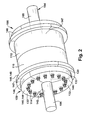
FIG. 2 shows a perspective view illustrating a sectioned tuning ring coupled to a flange coupling of a rotating body according to another embodiment of the invention. -
FIG. 3 shows a cross-sectional view of theFIG. 2 embodiment. -
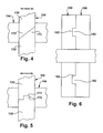
FIGS. 4-6 show cross-sectional detail views of various embodiments of mating elements between sections of the sectioned tuning rings in accordance with the different embodiments of the invention. -
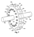
FIG. 7 shows a perspective view illustrating a sectioned tuning ring coupled to a flange coupling of a rotating body according to another embodiment of the invention. - It is noted that the drawings of the invention are not to scale. The drawings are intended to depict only typical aspects of the invention, and therefore should not be considered as limiting the scope of the invention.
- Referring to the drawing,
FIG. 1 shows a perspective view illustrating an apparatus including a sectionedtuning ring 100 coupled to aflange coupling 102 of a rotatingbody 104 according to embodiments of the invention. When sectionedtuning ring 100 is coupled to rotatingbody 104, it adjusts a frequency of the rotating body from what it would be without it. For example, sectionedtuning ring 100 may adjust a frequency of a torsional mode of rotatingbody 104 above or below a natural frequency of the torsional mode of the rotating body. Other adjustments may also be possible via sectionedtuning ring 100. - Rotating
body 104 may be any form of rotating body within any form of machine. In the most applicable settings, rotatingbody 104 may include a rotating shaft of, for example, a gas turbine, a steam turbine or a combined gas and steam turbine, or a rotor of an electro-dynamic machine such as a generator. As will become apparent, in the above-described settings, sectionedtuning ring 100 allows installation thereof and tuning of rotatingbody 104 without removing the rotating body from an operational position within a machine. That is, in contrast to conventional shrunk-on tuning rings, sectionedtuning ring 100 does not require removal of the rotating body so that it can be passed axially along its length to the flange coupling. Consequently, since rotatingbody 104 may remain in its operating position, tuning thereof does not require as much time and expense. As understood, rotatingbody 104 can be supported by any known means, e.g., bearings, in the machine.Flange coupling 102 couples afirst part 106 and asecond part 108 of rotatingbody 104 together. Afirst flange 110 is coupled tofirst part 106 and asecond flange 112 is coupled tosecond part 108.First flange 110 is coupled tosecond flange 112 by a plurality ofbolts 114. Rotatingbody 104 may extend throughflanges flanges - In one embodiment, sectioned
tuning ring 100 is mounted toflange coupling 102 using plurality ofbolts 114. That is, the same bolts used to couple flangedcoupling 102 may be used to mount sectionedtuning ring 100.Bolts 114, which may include ancillary structure such as nuts and/or washers therefor, may be modified compared to conventional bolts to withstand the additional stresses created by sectionedtuning ring 100. For examples,bolts 114 may have: different material; larger or smaller diameter on shaft, head or bolts; different threads (bolts and nuts also); different washers (if used); added seated areas; etc. In another embodiment, a first set of bolts may be used to coupleflange coupling 102 and another set of bolts may be used to mount sectionedtuning ring 100 to flangedcoupling 102. In this case, the sectioned tuning ring(s) 100 immediately adjacent to flangedcoupling 102 may include bolt accommodating openings (not shown) therein such as recesses for nuts. It is understood that this latter embodiment does not look any different than what is shown inFIGS. 2-3 . - In the
FIG. 1 embodiment, a single, sectionedtuning ring 100 is illustrated coupled to an axially facing surface 120 (behind ring 100) offlange coupling 102. However, as shown inFIGS. 2 and3 , in another embodiment, sectionedtuning ring 100 may include a plurality of axially positioned sectionedtuning rings 140. That is, one or more sectioned tuning ring(s) 110 may be coupled to each axially facing surface 120 (behind rings 100) offlange coupling 102. - In the
FIGS. 1-3 embodiments, sectionedtuning ring 100 includes a plurality of substantially planar andarcuate sections 130 positioned circumferentially adjacent one another so as to form a substantially planar ring that sits substantially perpendicular to rotatingbody 104. InFIG. 1 eacharcuate section 130 extends approximately 180°. InFIG. 2 , eacharcuate section 132 extends approximately 120°. - Where more than one sectioned
tuning ring 100 is used, adjacent sectionedtuning rings 100 need not have the same number ofsections 132. Practically any number of sections may be employed so long as they form a ring when put together. In one embodiment, as shown best inFIG. 2 , although it may not be necessary in all cases, ajoint 142 betweenadjacent sections 132 of a first sectioned tuning ring 144 does not overlap ajoint 146 betweenadjacent sections 147 of an axially adjacent second sectioned tuning ring 148. That is, either adjacent sectionedtuning rings 100 have the same number of joints and their joints are circumferentially offset (i.e., by mounting the rings at different rotational angles about rotating body 104), or theadjacent rings 100 do not include the same number of sections so their joints do not positionally match up. This offset positioning may be helpful in preventing movement of the sections. - As shown in
FIG. 3 , where more than one sectionedtuning ring 100 is used, the sectionedtuning rings 100 need not have the same diameter or axial extent. - Referring to
FIGS. 4-6 , each sectionedtuning ring 100 may include mating elements to resist different types of movement. For example,FIGS. 4 and 5 show cross-sectional detail views ofmating elements 170, 172 between circumferentiallyadjacent sections 132 to resist axial movement therebetween, i.e., as shown by double-headed arrows, parallel to rotatingbody 104. InFIG. 4 ,mating elements 170, 172 are mating angled surfaces on abutting faces ofarcuate sections 132. InFIG. 5 ,mating elements 170, 172 are tongue and groove type elements.FIG. 6 shows axiallyadjacent sections 132 of sectioned tuning rings 100 includingmating elements 180, 182 that are tongue and groove type elements. In this case,mating elements 180, 182 resist circumferential movement of sectioned tuningrings 100 therebetween, i.e., into and out of the page. It is understood that the mating elements shown are only illustrative and a wide variety of other mating elements or other techniques may be possible to resist movement. In addition, combinations of the above-described embodiments may be employed, e.g.,FIG. 4 and FIG. 6 mating elements together. -
FIG. 7 shows a perspective view of another embodiment of a sectionedtuning ring 200 according to the invention. In this case, sectionedtuning ring 200 is mounted to acircumferential surface 202 offlange coupling 102. Consequently, eachsection 232 is substantially arcuate and semi-circular. In this case, a plurality ofbolts 214 extend radially intoflange coupling 102 to mount sectionedtuning ring 200. Any number ofsections 232 may be employed.Joints 242 betweensections 232 of adjacent sectioned tuning rings 200 may be offset, but this is not necessary. While two sectioned tuning rings 200 have been illustrated, one for eachflange 110, 112 (latter now shown), sectionedtuning ring 200 may include a single ring or more than two. In operation, rotatingbody 104 may be provided in an operational position within a machine, e.g., with any structure coupled theretonear flange coupling 102 removed.Sectioned tuning ring 100 may then be mounted toflange coupling 102 withrotating body 104 in the operating position within a machine to adjust a frequency of the rotating body. Frequency testing may be conducted prior to the mounting to determine a physical characteristic of sectioned tuning ring(s) 100 necessary to properly tunerotating body 104. After mounting of an initial sectionedtuning ring 100, if it is discovered that further tuning is required, at least one physical characteristic of the sectioned tuning ring may be adjusted by replacing afirst section 132 with asecond section 132 having at least one different physical characteristic. The physical characteristic(s) may include, for example, material, weight, size (e.g., diameter or axial extent), stiffness, inertia, etc. Alternatively, one or more sectioned tuning rings 100 may be modified, added or removed to achieve the necessary tuning. - The change in physical characteristic(s) provided by sectioned tuning ring(s) 100, 200 will affect the torsional frequency of oscillation in
rotating body 104. In one example, an operator may be able to adjust sectioned tuning ring(s) 100, 200 such that the torsional frequency ofrotating body 104 is substantially the same as the natural frequency of the rotating body torsional mode of interest. Other tuning requirements are also achievable using sectioned tuning ring(s) 100, 200. Another advantage of some embodiments is that when two or more sectioned tuning rings 100, 200 are next to each other, with overlapping ends, thebolts 114 between the overlapping ends are loaded in shear and the rings may become self supporting. In this case, even though two or more sectioned tuning rings 100, 200 may be bolted to anintegral flange flanged coupling 102, it is not necessary nor does theflange coupling 102 have to be as substantial of a member as conventionally provided to carry the load. - That is, it may only be used to provide axial location.
- The terms "first," "second," and the like, herein do not denote any order, quantity, or importance, but rather are used to distinguish one element from another, and the terms "a" and "an" herein do not denote a limitation of quantity, but rather denote the presence of at least one of the referenced item. The modifier "about" used in connection with a quantity is inclusive of the stated value and has the meaning dictated by the context, (e.g., includes the degree of error associated with measurement of the particular quantity).
- While various embodiments are described herein, it will be appreciated from the specification that various combinations of elements, variations or improvements therein may be made by those skilled in the art, and are within the scope of the invention. In addition, many modifications may be made to adapt a particular situation or material to the teachings of the invention without departing from essential scope thereof. Therefore, it is intended that the invention not be limited to the particular embodiment disclosed as the best mode contemplated for carrying out this invention, but that the invention will include all embodiments falling within the scope of the appended claims.
Claims (17)
- An apparatus comprising:a sectioned tuning ring (100) mounted to a flange coupling (102) that couples a first part (106) and a second part (108) of a rotating body (104) together, the sectioned tuning ring (100) adjusting a frequency of the rotating body (104).
- The apparatus of claim 1, wherein the sectioned tuning ring (100) includes a plurality of arcuate sections (130) positioned circumferentially adjacent one another.
- The apparatus of claim 1 or 2, wherein the sectioned tuning ring (100) is mounted to an axially facing surface (120) of the flange coupling (102), wherein each section of the sectioned tuning ring (100) is substantially planar and arcuate.
- The apparatus of claim 3, wherein the sectioned tuning ring (100) includes a plurality of axially positioned sectioned tuning rings (144, 148).
- The apparatus of claim 4, wherein a joint (142) between adjacent sections of a first sectioned tuning ring (144) does not overlap a joint (146) between adjacent sections (147) of an axially adjacent second sectioned tuning ring (148).
- The apparatus of claim 4 or 5, wherein each sectioned tuning ring (100) includes at least one of: mating elements (170, 172) between axially adjacent sections to resist circumferential movement therebetween, and mating elements (180, 182) between circumferentially adjacent sections (132) to resist axially movement therebetween.
- The apparatus of any of claims 3 to 6, wherein the flanged coupling (102) includes a first flange (110) coupled to a second flange (112) by a plurality of bolts (114), and the sectioned tuning ring (100) is mounted to the flange coupling (102) using the plurality of bolts (114).
- The apparatus of claim 4, wherein the sectioned tuning ring (100) includes a pair of sectioned tuning rings (144, 148), one attached to each axially facing surface of the flange coupling (102).
- The apparatus of any preceding claim, wherein the rotating body (104) remains in an operating position during mounting of the sectioned tuning ring (100) on the flanged coupling (102).
- The apparatus of claim 1, wherein the sectioned tuning ring (200) is mounted to a circumferential surface (202) of the flange coupling (102), wherein each section (232) of the sectioned tuning ring (200) is substantially arcuate and semi-circular.
- A system comprising:a rotating body (104) including a first part (106) coupled to a second part (108) by a flanged coupling (102) and the apparatus as recited in any of claims 1 to 10.
- A method comprising:providing a rotating body (104) including a first part (106) coupled to a second part (108) by a flange coupling (102); andmounting a sectioned tuning ring (100) to the flange coupling (102) with the rotating body (104) in an operating position within a machine to adjust a frequency of the rotating body (104).
- The method of claim 12, further comprising adjusting at least one physical characteristic of the sectioned tuning ring (100) by replacing a first section with a second section having at least one different physical characteristic.
- The method of claim 13, wherein the at least one physical characteristic is selected from the group consisting of: weight, size, stiffness and inertia.
- The method of any of claims 12 to 14, wherein the sectioned tuning ring (100) includes a plurality of substantially planar arcuate sections (130) positioned circumferentially adjacent one another.
- The method of any of claims 12 to 14, wherein the sectioned tuning ring (100) includes a plurality of axially positioned sectioned tuning rings (144,148).
- The method of claim 12, wherein at least one of the axially spaced sectioned tuning rings includes a plurality of arcuate sections positioned circumferentially adjacent one another.
Applications Claiming Priority (1)
| Application Number | Priority Date | Filing Date | Title |
|---|---|---|---|
| US13/044,861 US20120227536A1 (en) | 2011-03-10 | 2011-03-10 | Sectioned tuning ring for rotating body |
Publications (1)
| Publication Number | Publication Date |
|---|---|
| EP2497972A2 true EP2497972A2 (en) | 2012-09-12 |
Family
ID=45894098
Family Applications (1)
| Application Number | Title | Priority Date | Filing Date |
|---|---|---|---|
| EP12158324A Withdrawn EP2497972A2 (en) | 2011-03-10 | 2012-03-06 | Sectioned tuning ring for rotating body |
Country Status (4)
| Country | Link |
|---|---|
| US (1) | US20120227536A1 (en) |
| EP (1) | EP2497972A2 (en) |
| JP (1) | JP2012191842A (en) |
| CN (1) | CN102705436A (en) |
Families Citing this family (12)
| Publication number | Priority date | Publication date | Assignee | Title |
|---|---|---|---|---|
| CN205166525U (en) * | 2013-03-15 | 2016-04-20 | 通用电气公司 | torsional frequency regulator |
| US9551398B2 (en) | 2013-03-15 | 2017-01-24 | General Electric Company | Torsional mode shifting |
| US9216495B2 (en) * | 2013-07-09 | 2015-12-22 | General Electric Company | Spacer |
| US20150192019A1 (en) * | 2014-01-07 | 2015-07-09 | General Electric Company | Rotor train torsional mode frequency tuning apparatus |
| DE102015218428A1 (en) * | 2014-10-03 | 2016-04-07 | Borgwarner Inc., Patent Department | DEVICES AND METHOD FOR ADJUSTING THE BALANCE OF THE ROTATION ARRANGEMENT OF A TURBOCHARGER |
| CN107734705A (en) | 2016-08-12 | 2018-02-23 | 中兴通讯股份有限公司 | The method and device of dynamic dispatching |
| CN108336839B (en) | 2018-01-26 | 2019-08-02 | 北京金风科创风电设备有限公司 | Rotor, motor, reinforcing ring tool and mounting method thereof |
| CN109038937B (en) * | 2018-09-04 | 2020-04-03 | 上海歌尔泰克机器人有限公司 | Motor, power system, unmanned aerial vehicle and balancing method |
| JP7369060B2 (en) | 2020-02-26 | 2023-10-25 | 三菱重工エンジン&ターボチャージャ株式会社 | Shaft coupling device and torsional natural frequency adjustment method |
| JP7467246B2 (en) * | 2020-06-10 | 2024-04-15 | 株式会社東芝 | Rotating Electric Machine |
| CN112008351B (en) * | 2020-07-10 | 2021-11-19 | 中国航发南方工业有限公司 | Torsion measuring ring assembling method and clamp |
| CN113036958B (en) * | 2021-04-30 | 2022-04-08 | 珠海格力节能环保制冷技术研究中心有限公司 | Rotor and motor |
Family Cites Families (13)
| Publication number | Priority date | Publication date | Assignee | Title |
|---|---|---|---|---|
| US477324A (en) * | 1892-06-21 | Fly-wheel | ||
| US1356024A (en) * | 1918-08-02 | 1920-10-19 | William E Sullivan | Shaft-coupling |
| US2198135A (en) * | 1938-11-15 | 1940-04-23 | Jesse L Strasburg | Engine vibration eliminator |
| DE727378C (en) * | 1939-01-18 | 1942-11-02 | Sulzer Ag | Torsional vibration damper for machine shafts |
| US2348941A (en) * | 1942-12-05 | 1944-05-16 | Packard Motor Car Co | Vibration damping device |
| US3207000A (en) * | 1961-08-23 | 1965-09-21 | Charles S White | Crankshaft damper |
| US3146612A (en) * | 1963-02-01 | 1964-09-01 | Michigan Wheel Company | Coupling |
| US3528316A (en) * | 1968-12-09 | 1970-09-15 | Kenneth E Hammer | Shaft balancer |
| US3559502A (en) * | 1969-07-24 | 1971-02-02 | Caterpillar Tractor Co | Pendulum damper |
| US4538079A (en) * | 1984-04-16 | 1985-08-27 | Mitsubishi Denki Kabushiki Kaisha | Flywheel device with compensation for non parallel plates |
| US5085289A (en) * | 1988-09-09 | 1992-02-04 | Chance John H | Shock-absorbing resilient coupling |
| US5058452A (en) * | 1990-05-08 | 1991-10-22 | University Of South Florida | Hybrid squeeze film damper for active control of rotors |
| JP2004053008A (en) * | 2002-05-31 | 2004-02-19 | Fukoku Co Ltd | Viscous damper |
-
2011
- 2011-03-10 US US13/044,861 patent/US20120227536A1/en not_active Abandoned
-
2012
- 2012-03-06 EP EP12158324A patent/EP2497972A2/en not_active Withdrawn
- 2012-03-08 JP JP2012051109A patent/JP2012191842A/en active Pending
- 2012-03-09 CN CN201210073603.5A patent/CN102705436A/en active Pending
Non-Patent Citations (1)
| Title |
|---|
| None |
Also Published As
| Publication number | Publication date |
|---|---|
| JP2012191842A (en) | 2012-10-04 |
| CN102705436A (en) | 2012-10-03 |
| US20120227536A1 (en) | 2012-09-13 |
Similar Documents
| Publication | Publication Date | Title |
|---|---|---|
| EP2497972A2 (en) | Sectioned tuning ring for rotating body | |
| EP3084130B1 (en) | Method of assembling a set of impellers through tie rods, impeller and turbomachine | |
| US8128353B2 (en) | Method and apparatus for matching the thermal mass and stiffness of bolted split rings | |
| US7923890B2 (en) | Apparatus for generator stator mounting | |
| EP3023580B1 (en) | Gas turbine with plurality of tie rods and method of assembling the same | |
| US8013481B2 (en) | Detuner for tuning torsional mode of a rotating body | |
| US8829760B2 (en) | Dynamoelectric machine support system | |
| JP2000199406A (en) | Fan decoupler for gas turbine engine | |
| US9388697B2 (en) | First stage compressor disk configured for balancing the compressor rotor assembly | |
| WO2014204612A1 (en) | Controlling end ring balance in pre-balancing spinning process | |
| JP2009036208A (en) | Rotor alignment system and method | |
| US9729017B2 (en) | Dynamoelectric machine support system having bolted springbar | |
| US7250699B2 (en) | Turbine generator vibration damper system | |
| EP2546460A2 (en) | Turbine engine and load reduction device thereof | |
| US20180216466A1 (en) | Methods and systems for rotating component balancing | |
| US20150192019A1 (en) | Rotor train torsional mode frequency tuning apparatus | |
| JP4287341B2 (en) | Gas turbine power generator and method for manufacturing the same | |
| US9366146B2 (en) | Closure bucket for turbo-machine | |
| US20140079547A1 (en) | Rotor assembly and refit method | |
| Murty et al. | Lateral and torsional vibration analysis of gas turbine rotor system | |
| Baxter | Troubleshooting Vibration Problems. A Compilation of Case Histories |
Legal Events
| Date | Code | Title | Description |
|---|---|---|---|
| PUAI | Public reference made under article 153(3) epc to a published international application that has entered the european phase |
Free format text: ORIGINAL CODE: 0009012 |
|
| AK | Designated contracting states |
Kind code of ref document: A2 Designated state(s): AL AT BE BG CH CY CZ DE DK EE ES FI FR GB GR HR HU IE IS IT LI LT LU LV MC MK MT NL NO PL PT RO RS SE SI SK SM TR |
|
| AX | Request for extension of the european patent |
Extension state: BA ME |
|
| STAA | Information on the status of an ep patent application or granted ep patent |
Free format text: STATUS: THE APPLICATION IS DEEMED TO BE WITHDRAWN |
|
| 18D | Application deemed to be withdrawn |
Effective date: 20141001 |