EP2497559A1 - A filter system for cleaning the air of an enclosure to be ventilated, especially for fiber-optic equipment - Google Patents
A filter system for cleaning the air of an enclosure to be ventilated, especially for fiber-optic equipment Download PDFInfo
- Publication number
- EP2497559A1 EP2497559A1 EP11401043A EP11401043A EP2497559A1 EP 2497559 A1 EP2497559 A1 EP 2497559A1 EP 11401043 A EP11401043 A EP 11401043A EP 11401043 A EP11401043 A EP 11401043A EP 2497559 A1 EP2497559 A1 EP 2497559A1
- Authority
- EP
- European Patent Office
- Prior art keywords
- filter housing
- filter
- shaft
- filter system
- opening
- Prior art date
- Legal status (The legal status is an assumption and is not a legal conclusion. Google has not performed a legal analysis and makes no representation as to the accuracy of the status listed.)
- Granted
Links
Images




Classifications
-
- B—PERFORMING OPERATIONS; TRANSPORTING
- B01—PHYSICAL OR CHEMICAL PROCESSES OR APPARATUS IN GENERAL
- B01D—SEPARATION
- B01D46/00—Filters or filtering processes specially modified for separating dispersed particles from gases or vapours
- B01D46/10—Particle separators, e.g. dust precipitators, using filter plates, sheets or pads having plane surfaces
-
- G—PHYSICS
- G02—OPTICS
- G02B—OPTICAL ELEMENTS, SYSTEMS OR APPARATUS
- G02B6/00—Light guides; Structural details of arrangements comprising light guides and other optical elements, e.g. couplings
- G02B6/24—Coupling light guides
- G02B6/36—Mechanical coupling means
- G02B6/38—Mechanical coupling means having fibre to fibre mating means
- G02B6/3807—Dismountable connectors, i.e. comprising plugs
- G02B6/3897—Connectors fixed to housings, casing, frames or circuit boards
Definitions
- the present invention relates to a filter system for cleaning the air of an enclosure to be ventilated, especially for fiber-optic equipment, the enclosure including a ventilation opening and being associated with an insertion shaft located proximate to the ventilation opening, the filter system including the features of the pre-characterizing portion of claim 1. Further, the invention relates to an enclosure.
- the respective front panel is usually rather small, which results in a correspondingly small space for connecting fibers or cables right in front of the panel, as often the casings of fiber-optic equipment are stacked one over the other in a mounting rack.
- the fiber-optic connecting cables are guided essentially horizontally in front of the panel to the right or left of the casing.
- the air filter systems are often designed such, that the housing for the air filter element can be accessed from the front panel in order to change the filter element.
- the ventilation opening of the casing is usually provided in the left or right side wall of the casing, the ventilation opening having a sufficiently large area and also a height that often extends over almost the entire height of the casing or at least over a considerable part of the height thereof.
- the air filter element covering the whole ventilation opening and the filter housing accommodating the filter element also extend over this part of the height of the casing.
- the invention is based on the notion that the insertion opening for inserting the filter housing into the insertion shaft located proximate to the ventilation opening does not necessarily need to extend in a plane parallel to the ventilation opening, if the system is designed such that the filter housing can be inserted into the insertion shaft in a first azimuthal orientation (with respect to the direction of insertion) and rotated into a second azimuthal orientation which corresponds to the azimuthal orientation of the working position of the filter housing after the filter housing has passed the insertion opening.
- the filter system can be adapted to use a given however large enough space in front of the filter system or the enclosure, respectively, even if this space is insufficient in directly inserting the filter housing into the insertion shaft in the azimuthal orientation of the working position.
- the insertion means includes a neck portion defining the insertion opening, the axial length of the neck portion corresponding to the axial length of the handle.
- the neck portion can be used as guiding means so that the filter housing can be inserted along a given direction of insertion defined by the neck portion.
- the outer front face of the neck portion can be used as mechanical stop for a grip element of the handle being used for manually rotating the filter housing during insertion.
- the filter housing preferably has an essentially constant cross-section in planes perpendicular to the insertion direction, and the cross-section of the insertion opening (in planes perpendicular to the insertion direction) preferably reveals the same shape, so that the filter housing can be inserted in a predefined azimuthal position.
- the handle preferably includes a shaft mounted to the filter housing and a grip element provided at the opposite end of the shaft, the grip element being adapted to close the insertion opening when the filter housing is in its working position.
- the intrusion of dust or dirt into the enclosure can be avoided at least if the neck portion reveals a circumferentially closed wall.
- the cross-sectional shape of the grip element equals the shape of the neck portion at its outer front face, the user is informed about the azimuthal position of the insertion part or the filter housing, respectively, by the azimuthal position of the grip element relative to the front face of the neck portion. In case the grip element is not in an aligned position with respect to the front face of the neck portion, this signals that the filter housing has not reached its working position.
- the grip element and the form of the neck portion can be designed such that the user is informed when the azimuthal position of the filter housing corresponds to the first azimuthal position allowing the insertion or pulling out of the insertion part into the insertion shaft.
- the insertion means includes a preferably plate-like sealing element having an opening corresponding to the cross-section of the rear portion of the filter housing, the sealing element being arranged such that the rear portion of the filter housing engages the sealing element when the insertion part is rotated from the first azimuthal position into the second azimuthal position and that the sealing element essentially seals the insertion opening in the working position.
- the plate-like sealing element may reveal a circular outer shape and may be rotatably held by a plate-like guide element having a circular recess in which the sealing element is rotatably guided.
- the insertion means may further include an inner guide element provided at the side of the sealing element facing the inner portion of the enclosure and an outer guide element provided at the opposite side of the sealing element, both guide elements having a recess configured such that the plate-like sealing element is sandwiched and rotatably held between the guide elements, the recess of the outer guide element being further configured such that it allows for the insertion of the filter housing in its first azimuthal position, and the recess of the inner guide element being further configured such that it allows for the insertion and rotational movement of the filter housing.
- an inner guide element provided at the side of the sealing element facing the inner portion of the enclosure and an outer guide element provided at the opposite side of the sealing element
- both guide elements having a recess configured such that the plate-like sealing element is sandwiched and rotatably held between the guide elements
- the recess of the outer guide element being further configured such that it allows for the insertion of the filter housing in its first azimuthal position
- the recess of the inner guide element being further configured such that
- the insertion means comprises an engaging element provided at the end portion of the filter housing opposite the handle, the engaging element being adapted to engage a complementary engaging element provided at an inner portion of the insertion shaft in an engaging status which is at the latest reached when the insertion part has been fully inserted in the insertion direction, the engaging element and the complementary engaging element enabling, in their engaging status, the rotational movement of the insertion part from the first into the second azimuthal position.
- the handle may be configured such that the filter housing is kept under prestress in the direction of insertion when the insertion part has been fully inserted in the insertion direction, at the latest when the working position has been reached. This prevents the insertion part from small axial movements and/or producing noise in its working position which may otherwise arise due to vibrations of the enclosure.
- the handle comprises a radially extending pin being adapted to engage a catch spring included by the insertion means when the insertion part is in its working position. In this way, the insertion part is secured against inadvertent movements and securely fixed in its working position.
- the handle may comprise a telescopic shaft having a first and a second telescope element being engaged by a spring element which forces the two telescope elements into an end position in which the maximum length of the handle is reached, the first telescope element being connected to the filter housing and comprising an elongate recess through which the pin extends, the radially extending pin being connected to the second telescope element.
- the pin which is attached to the second telescope element and which extends through the recess provided in the first telescope element serves as an end stop.
- the length of the recess in the direction of the axis of the telescope shaft determines the maximum variation of the telescope length.
- the first telescope element may be realized as a hollow cylinder (of arbitrary cross-section) and may encompass the second telescope element which may be a solid element having a corresponding cross-section so that it is guided within the first telescope element.
- the insertion opening has a rectangular cross-section corresponding to a respective rectangular cross-section of the filter housing of the insertion part, and the angular distance between the first and second azimuthal position is 90 degrees.
- This allows, for example, to provide a rectangular insertion opening with its longer axis arranged horizontally at a front panel of rather low (vertical) height so that the insertion part can be inserted with a respective "horizontal" orientation of the filter housing.
- the insertion part can be rotated by 90 degrees about an axis parallel to the insertion direction into the working position of the filter housing, in which the filter housing is positioned vertically (with its longer axis being vertical) within the respective insertion shaft, which may be adjacent to a ventilation opening provided in a vertical sidewall of the enclosure.
- the neck portion extends outside the enclosure and comprises cable guide means defining at least one cable guiding area located at the outer circumference of the neck portion. This ensures that the cables need not to be moved when the insertion part is pulled out or slid in.
- Fig. 1 shows a fiber-optic equipment 1 comprising an enclosure or casing 3.
- a plurality of jacks 7 are provided, each of the jacks 7 adapted to receive a fiber-optic connector 9 of a fiber-optic cable 11.
- the jacks 7 are provided in a slant manner such that the direction of insertion of the respective connector 9 is horizontal but inclined to the right side of the casing. This facilitates the guiding of the cables 11 in front of and close to the front panel 5 to the right. This allows stacking such fiber-optic equipment one over the other in a mounting rack without problems of interfering cables if a casing is to be taken out or a further casing is to be mounted into the rack.
- fastening brackets 13 are provided at the front outer side walls of the casing.
- the casing 3 includes an air filter system 15 provided at the right side of the casing 3 which, within the respective area of the front panel 5, also takes over the function of the front panel, namely, to essentially seal the casing against the intrusion of unfiltered air.
- the filter system 15 comprises an insertion means 16 for inserting an insertion part 25 ( Fig. 3 ) into an insertion shaft 18 ( Fig. 2 ) provided within the casing 3.
- the casing has in its outer right side wall a ventilation opening 20 ( Fig. 4 ) being associated with the insertion shaft 18 located proximate to the ventilation opening 20.
- the insertion means comprises a neck portion 17 extending rectangularly from the front side of the casing 3.
- the length of the neck portion 17 is preferably chosen such that it fully extends through the region in front of the front panel 5 needed to guide the cables 11 aside from the casing 3.
- the cables are guided in the region above and below the neck portion 13.
- Figs. 4 , 5 and 7 show additional guiding means 19 for keeping the cables within the space limited by the front panel and limiting elements 21 of the guiding means 19.
- the limiting elements 21 may be realized (as shown in the Figures) as plates or arms extending in a plane parallel to the front panel being mounted to the casing by distance rods 23. Due to the guiding means 19, the cables are kept in the respective region in front of the front panel 5 and do not impede the process of changing the filter element 33 ( Fig. 3 ) as described below.
- Fig. 2 shows the open casing 3 and its filter system 15 without the internal electronic or optic equipment.
- the insertion part 25 shown in Figs. 3a and 3b is kept in its working position, which means that a filter housing 27 of the insertion part 25 is affixed in its working position.
- the insertion part 25 comprises a filter housing 27 having a rectangular structure with elongate side walls 29 and shorter front and rear walls 31.
- the bottom of the filter housing 27 reveals recesses which enable the passing of air through a large extent of the bottom area.
- a filter element 33 which is encompassed by the filter housing, rests on supporting areas of the bottom of the filter housing 27 provided adjacent to the side walls 29 and the front and rear walls 31 a, 31 b. Further rests are realized as narrow stiffening members 35 connecting the side walls 29.
- retainer means 35 On its upper side the filter element 33 is retained with the filter housing by retainer means 35, which may be realized as portions of the sidewalls and/or rear walls crimped inwardly, so that the flexible filter element 33 can be inserted in the interior of the filter housing 27.
- the insertion part 25 further comprises a handle 37 consisting of a shaft 39 connected to the front wall 31 a and a grip element 41 connected to the other end of the shaft 39.
- the shaft 39 may be designed as telescopic shaft comprising a first telescope element 43 connected to the front wall 31 a which is a hollow cylindrical element encompassing a second telescope element 45 in the form of a cylindrical pin.
- a spring element 47 surrounds the pin-like second telescope element 45 and engages, with one end thereof, a step or shoulder 45a of the pin-like element. The other end of the spring element 47 engages a shoulder provided in the inner surface of the first telescope element 43 (not shown).
- a transverse elongated recess 43a is provided in the inner end of the pin-like first telescope element 43. Additionally, a transversely extending bore 45b is provided in the inner end of the second telescope element 45.
- the handle 37 is assembled by sliding the spring element 47 onto the inner end of the second telescope element 45 and inserting this inner end into the cylindrical first telescope element 43 until the transverse bore 45b in the second telescope element 45 reaches the transverse recess 43a. Then, a pin 49 is inserted through the recess 43a into the bore 45b such that it radially extends for a given length which may serve to engage a catch spring 51 ( Fig. 4 ) included by the insertion means when the insertion part is in its working position.
- the telescope shaft 39 is designed such that a pre-stress acts upon the filter housing 27 when the insertion part is in its working position (shown in Figs. 1 , 2 and 7 ), as the axial position of the insertion part in the direction of the insertion movement (or the axis of the neck portion 17) is fixed by the pin 49 and the catch spring 51 so that the spring element 47 exerts a pre-stressing force onto the first telescope element 43 and the filter housing 27 (the respective movement being limited by the elongated hole 43a and the pin 49).
- the insertion part 25 must be rotated counterclockwise by 90 degrees in order to move the filter housing 27 from its working position (in which the filter housing is fixed upright within the insertion shaft ( Fig. 2 )) to a horizontal position in which the cross-section of the filter housing 27 is aligned with the cross-section of the insertion opening 53 of the insertion means 19 defined by the neck portion 17.
- the term "cross-section of the filter housing” means the cross-section of the filter housing 27 in planes perpendicular to its longitudinal axis (which is parallel to the side walls 29) or perpendicular to the direction of insertion.
- the term "cross-section of the insertion opening” means the cross-section of the opening 53 in planes perpendicular to the direction of insertion (or perpendicular to the longitudinal axis of the neck portion 17).
- the insertion part with its filter housing can be pulled out of the insertion means comprising the neck portion 17 defining the square insertion opening, the cross-section of which is slightly bigger than the square cross-section of the filter housing 27.
- the shape of the cross-section of the filter housing 27 equal the shape of the cross-section of the insertion opening.
- the shape of the cross-section of the insertion opening in planes perpendicular to the insertion direction shall be configured such that the filter housing of the insertion part can be inserted into the insertion shaft in a predefined first azimuthal insertion position, only, and that the filter housing can be rotated from the first azimuthal insertion position into a second azimuthal position corresponding to the working position after the filter housing of the insertion part has been fully inserted through the insertion opening.
- Inserting the insertion part 25 into the insertion shaft 18 is effected vice versa.
- the front of the insertion part 25, i.e. the cross-section of the filter housing 27, is aligned with the insertion opening 53 and is then slid in until an engaging element 55 in the form of a pin provided at the rear wall 31 b of the filter housing 27 engages a complementary engaging element 57 in the form of a recess provided in an inner wall of the casing 3.
- the pin 55 and the recess 57 cooperate to guide the insertion part in the longitudinal direction and further enable to pivot the insert element from its azimuthal (horizontal) insertion position to the (vertical) working position.
- the outer vertical dimension of the handle 37 in the longitudinal region of the neck portion 17 essentially equals the vertical dimension of the filter housing 27. If the outer diameter of the first telescope element 43 equals the height of the side walls 29, 31 of the filter housing the insertion part 25 is still smoothly guided in the neck portion 17 even if the filter housing 27 has almost passed the neck portion 17.
- the grip element 41 has a cross-section (in planes perpendicular to the longitudinal axis) which is essentially equal to the cross-section of the neck portion 17 (of course the cross-section of the grip element might also be bigger) the grip element 41 seals the front opening of the neck portion 17 when the insertion part 25 is in its working position. Moreover, the elongated cross-section of the grip elememt 41 serves as indicator for the azimuthal position of the insertion part 25. If the grip element indicates a 90 degrees position, the insert element can be pulled out of the insertion shaft 18.
- the insertion means comprise a plate-like sealing element 59 having an opening 61 corresponding to the cross-section of the rear portion of the filter housing.
- the sealing element 59 (and of course the longitudinal position of the engaging element 57) is arranged such that the rear portion of the filter housing 27 engages the sealing element 59 when the insertion part 25 is rotated from the azimuthal insertion position into the azimuthal position of the working position. In this way, the sealing element 59 essentially seals the insertion opening 53 during inserting the insertion part 25 and in the working position.
- the plate-like sealing element 59 has a circular outer shape and is rotatably held by a plate-like guide element 63 having a circular recess 63a in which the sealing element 59 is rotatably guided.
- the insertion means further includes an inner guide element 65 provided at the side of the sealing element 59 facing the inner portion of the enclosure 3 and an outer guide element 67 provided at the opposite side of the sealing element 59.
- Each of the guide elements 65, 67 comprises a recess configured such that the plate-like sealing element 59 is sandwiched and rotatably held between the guide elements 65, 67.
- the recess of the outer guide element 67 is configured such that it allows for the insertion of the filter housing 27 and may be equal to and aligned to the cross-section of the insertion opening 53.
- the recess of the inner guide element 65 is configured such that it not only allows for the insertion but also for the rotational movement of the filter housing 27.
- the outer guide element 67 has a lower recess 67a that corresponds to the insertion opening 53.
- the further recess 67b facilitates the manufacturing of the catch spring 51 which may be manufactured by a cold forming process after the two recesses 67a, 67b have been punched out of a metal sheet.
- the neck portion 17 reveals a recess on the left side adjacent to the front panel 5 or the outer guide element 67, respectively.
Landscapes
- Chemical & Material Sciences (AREA)
- Chemical Kinetics & Catalysis (AREA)
- Filtering Of Dispersed Particles In Gases (AREA)
Abstract
Description
- The present invention relates to a filter system for cleaning the air of an enclosure to be ventilated, especially for fiber-optic equipment, the enclosure including a ventilation opening and being associated with an insertion shaft located proximate to the ventilation opening, the filter system including the features of the pre-characterizing portion of
claim 1. Further, the invention relates to an enclosure. - Especially in casings for fiber-optic equipment there is often the need to change the filter element of an air filter system of the casing without moving fiber-optic cables or pigtails which are connected to fiber-optic jacks provided at a front plane of the casing. Each movement of a fiber-optic cable may change the transmission characteristics of the respective transmission link, especially the attenuation of the link due to a small bending radius. Also, if actions like changing filter elements are carried out by untrained personnel, there is a risk that the fiber-optic connectors received in respective jacks at the front plane are torn out or the cables are treated such that the fibers break, both resulting in a complete loss of signal in the respective transmission link. As the enclosure of a fiber optic equipment is usually kept as small as possible in order to save space, the respective front panel is usually rather small, which results in a correspondingly small space for connecting fibers or cables right in front of the panel, as often the casings of fiber-optic equipment are stacked one over the other in a mounting rack.
- Often, the fiber-optic connecting cables are guided essentially horizontally in front of the panel to the right or left of the casing. Further, the air filter systems are often designed such, that the housing for the air filter element can be accessed from the front panel in order to change the filter element. In these embodiments for an air filter system, the ventilation opening of the casing is usually provided in the left or right side wall of the casing, the ventilation opening having a sufficiently large area and also a height that often extends over almost the entire height of the casing or at least over a considerable part of the height thereof. As a result, the air filter element covering the whole ventilation opening and the filter housing accommodating the filter element also extend over this part of the height of the casing. If in front of the air filter system the fiber-optic connecting cables are to be guided to the respective side of the casing or rack, it is, practically impossible in case of know air filter systems to pull the filter housing out from the casing without moving aside the fiber-optic connecting cables, which involves the afore-mentioned risks.
- It is desirable in case of these embodiments of casings for fiber-optic equipment including an air cleaning filter system to use a rather small height of the front panel for both guiding fiber-optic connecting cables and accessing the filter system without the risk or with a reduced risk to affect the transmission characteristics of the respective transmission links by moving the cables or even breaking or disconnecting the fibers from the front panel.
- It is thus an object of the invention to provide a filter system for cleaning the air of an enclosure to be ventilated, especially for fiber-optic equipment, which is configurable such that only a minimum space in a given direction is required in order to access the filter system for changing the filter element, even if the ventilation opening does not extend in a plane parallel to the given direction. It is a further object of the invention to provide an enclosure including such a filter system.
- The invention achieves these objects by the combination of the features of
claims 1 and 14, respectively. - The invention is based on the notion that the insertion opening for inserting the filter housing into the insertion shaft located proximate to the ventilation opening does not necessarily need to extend in a plane parallel to the ventilation opening, if the system is designed such that the filter housing can be inserted into the insertion shaft in a first azimuthal orientation (with respect to the direction of insertion) and rotated into a second azimuthal orientation which corresponds to the azimuthal orientation of the working position of the filter housing after the filter housing has passed the insertion opening. In this way, the filter system can be adapted to use a given however large enough space in front of the filter system or the enclosure, respectively, even if this space is insufficient in directly inserting the filter housing into the insertion shaft in the azimuthal orientation of the working position.
- According to a preferred embodiment of the invention, the insertion means includes a neck portion defining the insertion opening, the axial length of the neck portion corresponding to the axial length of the handle. In this way, the neck portion can be used as guiding means so that the filter housing can be inserted along a given direction of insertion defined by the neck portion. In addition, the outer front face of the neck portion can be used as mechanical stop for a grip element of the handle being used for manually rotating the filter housing during insertion.
- The filter housing preferably has an essentially constant cross-section in planes perpendicular to the insertion direction, and the cross-section of the insertion opening (in planes perpendicular to the insertion direction) preferably reveals the same shape, so that the filter housing can be inserted in a predefined azimuthal position.
- The handle preferably includes a shaft mounted to the filter housing and a grip element provided at the opposite end of the shaft, the grip element being adapted to close the insertion opening when the filter housing is in its working position. In this way, the intrusion of dust or dirt into the enclosure can be avoided at least if the neck portion reveals a circumferentially closed wall. Moreover, if the cross-sectional shape of the grip element equals the shape of the neck portion at its outer front face, the user is informed about the azimuthal position of the insertion part or the filter housing, respectively, by the azimuthal position of the grip element relative to the front face of the neck portion. In case the grip element is not in an aligned position with respect to the front face of the neck portion, this signals that the filter housing has not reached its working position.
- Moreover, the grip element and the form of the neck portion can be designed such that the user is informed when the azimuthal position of the filter housing corresponds to the first azimuthal position allowing the insertion or pulling out of the insertion part into the insertion shaft.
- According to a preferred embodiment of the invention, the insertion means includes a preferably plate-like sealing element having an opening corresponding to the cross-section of the rear portion of the filter housing, the sealing element being arranged such that the rear portion of the filter housing engages the sealing element when the insertion part is rotated from the first azimuthal position into the second azimuthal position and that the sealing element essentially seals the insertion opening in the working position. Thus, the intrusion of dust or dirt by sucking in unfiltered air is avoided.
- The plate-like sealing element may reveal a circular outer shape and may be rotatably held by a plate-like guide element having a circular recess in which the sealing element is rotatably guided.
- The insertion means may further include an inner guide element provided at the side of the sealing element facing the inner portion of the enclosure and an outer guide element provided at the opposite side of the sealing element, both guide elements having a recess configured such that the plate-like sealing element is sandwiched and rotatably held between the guide elements, the recess of the outer guide element being further configured such that it allows for the insertion of the filter housing in its first azimuthal position, and the recess of the inner guide element being further configured such that it allows for the insertion and rotational movement of the filter housing. In this way, simple and cheap construction and manufacturing of the rotatable sealing element are achieved.
- According to another embodiment of the invention, the insertion means comprises an engaging element provided at the end portion of the filter housing opposite the handle, the engaging element being adapted to engage a complementary engaging element provided at an inner portion of the insertion shaft in an engaging status which is at the latest reached when the insertion part has been fully inserted in the insertion direction, the engaging element and the complementary engaging element enabling, in their engaging status, the rotational movement of the insertion part from the first into the second azimuthal position. This guarantees a smooth insertion of the insertion part into the insertion shaft and a secure retention of the insertion part in its working position.
- The handle may be configured such that the filter housing is kept under prestress in the direction of insertion when the insertion part has been fully inserted in the insertion direction, at the latest when the working position has been reached. This prevents the insertion part from small axial movements and/or producing noise in its working position which may otherwise arise due to vibrations of the enclosure.
- In a further embodiment of the invention, the handle comprises a radially extending pin being adapted to engage a catch spring included by the insertion means when the insertion part is in its working position. In this way, the insertion part is secured against inadvertent movements and securely fixed in its working position.
- The handle may comprise a telescopic shaft having a first and a second telescope element being engaged by a spring element which forces the two telescope elements into an end position in which the maximum length of the handle is reached, the first telescope element being connected to the filter housing and comprising an elongate recess through which the pin extends, the radially extending pin being connected to the second telescope element. Thus, the pin which is attached to the second telescope element and which extends through the recess provided in the first telescope element serves as an end stop. The length of the recess in the direction of the axis of the telescope shaft determines the maximum variation of the telescope length. In a specific embodiment, the first telescope element may be realized as a hollow cylinder (of arbitrary cross-section) and may encompass the second telescope element which may be a solid element having a corresponding cross-section so that it is guided within the first telescope element.
- In a preferred embodiment ,the insertion opening has a rectangular cross-section corresponding to a respective rectangular cross-section of the filter housing of the insertion part, and the angular distance between the first and second azimuthal position is 90 degrees. This allows, for example, to provide a rectangular insertion opening with its longer axis arranged horizontally at a front panel of rather low (vertical) height so that the insertion part can be inserted with a respective "horizontal" orientation of the filter housing. After the filter housing has been fully inserted through the insertion opening, the insertion part can be rotated by 90 degrees about an axis parallel to the insertion direction into the working position of the filter housing, in which the filter housing is positioned vertically (with its longer axis being vertical) within the respective insertion shaft, which may be adjacent to a ventilation opening provided in a vertical sidewall of the enclosure.
- According to the preferred embodiment, the neck portion extends outside the enclosure and comprises cable guide means defining at least one cable guiding area located at the outer circumference of the neck portion. This ensures that the cables need not to be moved when the insertion part is pulled out or slid in.
- Further embodiments are apparent from the dependent claims. These and other advantages and features of the invention will be apparent from the following description of the preferred embodiment, considered along with the accompanying drawings. In the drawings, the respective Figures show:
- Fig. 1
- a perspective view of the right front portion of an enclosure of a fiber-optic equipment including a filter system according to a preferred embodiment of the invention, the insertion part being in its working position;
- Fig. 2
- a similar perspective view as shown in
Fig. 1 without the top wall of the enclosure, the filter housing being in its working position; - Fig. 3
- perspective views of the insertion part of the filter system shown in
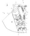
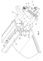
Figs. 1 and3 in its assembled status (Fig. 3a ) and in an exploded status (Fig. 3b ); - Fig. 4
- an enlarged perspective view of the open front portion of the embodiment shown in
Figs. 1 to 3 , the filter housing being in a 45° position; - Fig. 5
- an enlarged perspective inner view of the portion shown in
Fig. 4 , the filter housing being in a 45° position; - Fig. 6
- the sandwich-like construction of the rotatable sealing element used in the embodiment shown in
Figs. 1 to 5 ; and - Fig. 7
- an enlarged perspective inner view of the portion shown in
Fig. 4 , the filter housing being in its working position; -
Fig. 1 shows a fiber-optic equipment 1 comprising an enclosure orcasing 3. At afront panel 5 of thehousing 3, a plurality ofjacks 7 are provided, each of thejacks 7 adapted to receive a fiber-optic connector 9 of a fiber-optic cable 11. Thejacks 7 are provided in a slant manner such that the direction of insertion of therespective connector 9 is horizontal but inclined to the right side of the casing. This facilitates the guiding of thecables 11 in front of and close to thefront panel 5 to the right. This allows stacking such fiber-optic equipment one over the other in a mounting rack without problems of interfering cables if a casing is to be taken out or a further casing is to be mounted into the rack. For mounting thecasing 3 in a rack,fastening brackets 13 are provided at the front outer side walls of the casing. - The
casing 3 includes anair filter system 15 provided at the right side of thecasing 3 which, within the respective area of thefront panel 5, also takes over the function of the front panel, namely, to essentially seal the casing against the intrusion of unfiltered air. Thefilter system 15 comprises an insertion means 16 for inserting an insertion part 25 (Fig. 3 ) into an insertion shaft 18 (Fig. 2 ) provided within thecasing 3. The casing has in its outer right side wall a ventilation opening 20 (Fig. 4 ) being associated with theinsertion shaft 18 located proximate to theventilation opening 20. - The insertion means comprises a
neck portion 17 extending rectangularly from the front side of thecasing 3. The length of theneck portion 17 is preferably chosen such that it fully extends through the region in front of thefront panel 5 needed to guide thecables 11 aside from thecasing 3. As shown inFigs. 1 and2 , the cables are guided in the region above and below theneck portion 13.Figs. 4 ,5 and7 show additional guiding means 19 for keeping the cables within the space limited by the front panel and limitingelements 21 of the guiding means 19. The limitingelements 21 may be realized (as shown in the Figures) as plates or arms extending in a plane parallel to the front panel being mounted to the casing bydistance rods 23. Due to the guiding means 19, the cables are kept in the respective region in front of thefront panel 5 and do not impede the process of changing the filter element 33 (Fig. 3 ) as described below. -
Fig. 2 shows theopen casing 3 and itsfilter system 15 without the internal electronic or optic equipment. Theinsertion part 25 shown inFigs. 3a and 3b is kept in its working position, which means that afilter housing 27 of theinsertion part 25 is affixed in its working position. - As apparent from
Fig. 3 , theinsertion part 25 comprises afilter housing 27 having a rectangular structure withelongate side walls 29 and shorter front and rear walls 31. The bottom of thefilter housing 27 reveals recesses which enable the passing of air through a large extent of the bottom area. Afilter element 33, which is encompassed by the filter housing, rests on supporting areas of the bottom of thefilter housing 27 provided adjacent to theside walls 29 and the front andrear walls narrow stiffening members 35 connecting theside walls 29. On its upper side thefilter element 33 is retained with the filter housing by retainer means 35, which may be realized as portions of the sidewalls and/or rear walls crimped inwardly, so that theflexible filter element 33 can be inserted in the interior of thefilter housing 27. - The
insertion part 25 further comprises ahandle 37 consisting of ashaft 39 connected to thefront wall 31 a and agrip element 41 connected to the other end of theshaft 39. Theshaft 39 may be designed as telescopic shaft comprising afirst telescope element 43 connected to thefront wall 31 a which is a hollow cylindrical element encompassing asecond telescope element 45 in the form of a cylindrical pin. Aspring element 47 surrounds the pin-likesecond telescope element 45 and engages, with one end thereof, a step orshoulder 45a of the pin-like element. The other end of thespring element 47 engages a shoulder provided in the inner surface of the first telescope element 43 (not shown). A transverseelongated recess 43a is provided in the inner end of the pin-likefirst telescope element 43. Additionally, a transversely extendingbore 45b is provided in the inner end of thesecond telescope element 45. - The
handle 37 is assembled by sliding thespring element 47 onto the inner end of thesecond telescope element 45 and inserting this inner end into the cylindricalfirst telescope element 43 until thetransverse bore 45b in thesecond telescope element 45 reaches thetransverse recess 43a. Then, apin 49 is inserted through therecess 43a into thebore 45b such that it radially extends for a given length which may serve to engage a catch spring 51 (Fig. 4 ) included by the insertion means when the insertion part is in its working position. - Thus, the
telescope shaft 39 is designed such that a pre-stress acts upon thefilter housing 27 when the insertion part is in its working position (shown inFigs. 1 ,2 and7 ), as the axial position of the insertion part in the direction of the insertion movement (or the axis of the neck portion 17) is fixed by thepin 49 and thecatch spring 51 so that thespring element 47 exerts a pre-stressing force onto thefirst telescope element 43 and the filter housing 27 (the respective movement being limited by theelongated hole 43a and the pin 49). - As apparent from
Fig. 4 , theinsertion part 25 must be rotated counterclockwise by 90 degrees in order to move thefilter housing 27 from its working position (in which the filter housing is fixed upright within the insertion shaft (Fig. 2 )) to a horizontal position in which the cross-section of thefilter housing 27 is aligned with the cross-section of theinsertion opening 53 of the insertion means 19 defined by theneck portion 17. In this regard, the term "cross-section of the filter housing" means the cross-section of thefilter housing 27 in planes perpendicular to its longitudinal axis (which is parallel to the side walls 29) or perpendicular to the direction of insertion. In the same way, the term "cross-section of the insertion opening" means the cross-section of theopening 53 in planes perpendicular to the direction of insertion (or perpendicular to the longitudinal axis of the neck portion 17). - In the aligned position, the insertion part with its filter housing can be pulled out of the insertion means comprising the
neck portion 17 defining the square insertion opening, the cross-section of which is slightly bigger than the square cross-section of thefilter housing 27. - It is of course not mandatory that the shape of the cross-section of the
filter housing 27 equal the shape of the cross-section of the insertion opening. However, the shape of the cross-section of the insertion opening in planes perpendicular to the insertion direction shall be configured such that the filter housing of the insertion part can be inserted into the insertion shaft in a predefined first azimuthal insertion position, only, and that the filter housing can be rotated from the first azimuthal insertion position into a second azimuthal position corresponding to the working position after the filter housing of the insertion part has been fully inserted through the insertion opening. - Inserting the
insertion part 25 into theinsertion shaft 18 is effected vice versa. The front of theinsertion part 25, i.e. the cross-section of thefilter housing 27, is aligned with theinsertion opening 53 and is then slid in until an engagingelement 55 in the form of a pin provided at therear wall 31 b of thefilter housing 27 engages a complementaryengaging element 57 in the form of a recess provided in an inner wall of thecasing 3. Thepin 55 and therecess 57 cooperate to guide the insertion part in the longitudinal direction and further enable to pivot the insert element from its azimuthal (horizontal) insertion position to the (vertical) working position. - As apparent from
Fig. 3 , it is advantageous if the outer vertical dimension of thehandle 37 in the longitudinal region of the neck portion 17 (if the insertion part fully inserted in the longitudinal direction) essentially equals the vertical dimension of thefilter housing 27. If the outer diameter of thefirst telescope element 43 equals the height of theside walls 29, 31 of the filter housing theinsertion part 25 is still smoothly guided in theneck portion 17 even if thefilter housing 27 has almost passed theneck portion 17. - As the
grip element 41 has a cross-section (in planes perpendicular to the longitudinal axis) which is essentially equal to the cross-section of the neck portion 17 (of course the cross-section of the grip element might also be bigger) thegrip element 41 seals the front opening of theneck portion 17 when theinsertion part 25 is in its working position. Moreover, the elongated cross-section of thegrip elememt 41 serves as indicator for the azimuthal position of theinsertion part 25. If the grip element indicates a 90 degrees position, the insert element can be pulled out of theinsertion shaft 18. - Essentially in the plane of the front panel, the insertion means comprise a plate-
like sealing element 59 having anopening 61 corresponding to the cross-section of the rear portion of the filter housing. The sealing element 59 (and of course the longitudinal position of the engaging element 57) is arranged such that the rear portion of thefilter housing 27 engages the sealingelement 59 when theinsertion part 25 is rotated from the azimuthal insertion position into the azimuthal position of the working position. In this way, the sealingelement 59 essentially seals theinsertion opening 53 during inserting theinsertion part 25 and in the working position. - As is apparent from
Fig. 6 , the plate-like sealing element 59 has a circular outer shape and is rotatably held by a plate-like guide element 63 having acircular recess 63a in which the sealingelement 59 is rotatably guided. - The insertion means further includes an
inner guide element 65 provided at the side of the sealingelement 59 facing the inner portion of theenclosure 3 and anouter guide element 67 provided at the opposite side of the sealingelement 59. Each of theguide elements like sealing element 59 is sandwiched and rotatably held between theguide elements outer guide element 67 is configured such that it allows for the insertion of thefilter housing 27 and may be equal to and aligned to the cross-section of theinsertion opening 53. The recess of theinner guide element 65 is configured such that it not only allows for the insertion but also for the rotational movement of thefilter housing 27. - As shown in
Fig. 4 , theouter guide element 67 has a lower recess 67a that corresponds to theinsertion opening 53. Thefurther recess 67b facilitates the manufacturing of thecatch spring 51 which may be manufactured by a cold forming process after the tworecesses 67a, 67b have been punched out of a metal sheet. In order to enable thepin 49 to engage with thecatch spring 51 theneck portion 17 reveals a recess on the left side adjacent to thefront panel 5 or theouter guide element 67, respectively. -
- 1
- fiber-optic equipment
- 3
- enclosure, casing
- 5
- front panel
- 7
- jack
- 9
- fiber-optic connector
- 11
- fiber-optic cable
- 13
- bracket
- 15
- air filter system
- 16
- insertion means
- 17
- neck portion
- 18
- insertion shaft
- 19
- guiding means
- 20
- ventilation opening
- 21
- limiting element
- 23
- distance rods
- 25
- insertion part
- 27
- filter housing
- 29
- side walls
- 31a
- front wall
- 31b
- rear wall
- 33
- filter element
- 35
- retainer means
- 37
- handle
- 39
- shaft
- 41
- grip element
- 43
- first telescope element
- 43a
- transverse elongated recess
- 45
- second telescope element
- 45a
- shoulder
- 45b
- transverse bore
- 47
- spring element
- 49
- pin
- 51
- catch spring
- 53
- insertion opening
- 55
- engaging element / pin
- 57
- complementary engaging element
- 59
- sealing element
- 61
- opening
- 63
- guide element
- 65
- inner guide element
- 67
- outer guide element
- 67a
- recess
- 67b
- recess
Claims (14)
- A filter system for cleaning the air of an enclosure to be ventilated, especially for fiber-optic equipment, the enclosure (3) including a ventilation opening (20) and being associated with an insertion shaft (18) located proximate to the ventilation opening (20), the filter system (15) including(a) an insertion part (25) including a filter housing (27) for accommodating at least one filter element (33) and further including a handle (37) for inserting the insertion part (25) into the insertion shaft, the filter housing (3) being configured so as to cover the ventilation opening (20) when the filter housing (27) is in a working position within the insertion shaft (18); and(b) an insertion means (16) provided at a first end portion of the insertion shaft (18) for inserting the insertion part (25) into the insertion shaft (18);
characterized in(c) that the insertion means (16) defines an insertion opening (53) for inserting the insertion part (25) into the insertion shaft (18) in a given insertion direction, and(d) that the insertion opening (53) is stationary with respect to the enclosure (3), and the shape of the cross-section of the insertion opening (53) in planes perpendicular to the insertion direction is configured such that the filter housing (3) of the insertion part (25) can be inserted into the insertion shaft (18) in a predefined first azimuthal insertion position, only, and that the filter housing (27) can be rotated from the first azimuthal insertion position into a second azimuthal position corresponding to the azimuthal orientation of the working position after the filter housing (27) of the insertion part (25) has been fully inserted through the insertion opening (53). - A filter system according to claim 1, characterized in that the insertion means (16) includes a neck portion (17) defining the insertion opening (53), the axial length of the neck portion (17) corresponding to the axial length of the handle (37).
- A filter system according to claims 1 or 2, characterized in that the filter housing (27) has an essentially constant cross-section in planes perpendicular to the insertion direction and that the cross-section of the insertion opening (53) reveals the same shape.
- A filter system according to one of the preceding claims, characterized in that the handle (37) includes a shaft (39) mounted to the filter housing (27) and a grip element (41) provided at the opposite end of the shaft (39), the grip element (41) being adapted to close the insertion opening (53) when the filter housing (27) is in its working position.
- A filter system according to one of the preceding claims, characterized in that the insertion means (16) includes a preferably plate-like sealing element (59) having an opening (61) corresponding to the cross-section of the rear portion of the filter housing (27), the sealing element (59) being arranged such that the rear portion of the filter housing (27) engages the sealing element (59) when the insertion part (25) is rotated from the first azimuthal position into the second azimuthal position and that the sealing element (59) essentially seals the insertion opening (53) in the working position.
- A filter system according to claim 5, characterized in that the plate-like sealing element (59) has a circular outer shape and is rotatably held by a plate-like guide element (63) having a circular recess (63a) in which the sealing element (59) is rotatably guided.
- A filter system according to claim 6, characterized in that the insertion means (16) further includes an inner guide element (65) provided at the side of the sealing element (59) facing the inner portion of the enclosure (3) and an outer guide element (67) provided at the opposite side of the sealing element (59), both guide elements (65, 67) having a recess configured such that the plate-like sealing element (59) is sandwiched and rotatably held between the guide elements (65, 67), the recess of the outer guide element (67) being further configured such that it allows for the insertion of the filter housing (27) in its first azimuthal position, and the recess of the inner guide element (65) being further configured such that it allows for the insertion and rotational movement of the filter housing (27).
- A filter system according to one of the preceding claims, characterized in that the insertion part (25) comprises an engaging element (55) provided at the end portion of the filter housing (27) opposite the handle (37), the engaging element (55) being adapted to engage a complementary engaging element (57) provided at an inner portion of the insertion shaft (18) in an engaging status which is at the latest reached when the insertion part (25) has been fully inserted into the insertion shaft (18) in the insertion direction, the engaging element (55) and the complementary engaging element (57) enabling, in their engaging status, the rotational movement of the insertion part (25) from the first into the second azimuthal position.
- A filter system according to claim 8, characterized in that the handle (37) is configured such that the filter housing (27) is kept under pre-stress in the direction of insertion when the insertion part (25) has been fully inserted into the insertion shaft (18) in the insertion direction, at the latest when the working position has been reached.
- A filter system according to one of the preceding claims, characterized in that the handle (37) comprises a radially extending pin (49) being adapted to engage a catch spring (51) included by the insertion means (16) when the insertion part (18) is in its working position.
- A filter system according to one of claims 9 or 10, characterized in that the handle (37) comprises a telescopic shaft (39) having a first (43) and a second (45) telescope element being engaged by a spring element (47) forcing the two telescope elements (43, 45) into an end position in which the maximum length of the handle (37) is reached, the first telescope element (43) being connected to the filter housing (27) and comprising an elongate recess (43a) through which the pin (49) extends, the radially extending pin (49) being connected to the second telescope element (45).
- A filter system according to one of the preceding claims, characterized in that the insertion opening (53) has a rectangular cross-section and that the angular distance between the first and second azimuthal position is 90 degrees.
- A filter system according to one of claims 2 to 12, characterized in that the neck portion (17) extends outside the enclosure (3) and comprises cable guiding means (19) defining at least one cable guiding area located at the outer circumference of the neck portion (17).
- An enclosure comprising a filter system (15) according to one of the preceding claims.
Priority Applications (2)
| Application Number | Priority Date | Filing Date | Title |
|---|---|---|---|
| EP11401043.2A EP2497559B1 (en) | 2011-03-11 | 2011-03-11 | A filter system for cleaning the air of an enclosure to be ventilated, especially for fiber-optic equipment |
| US13/315,183 US8580007B2 (en) | 2011-03-11 | 2011-12-08 | Filter system for cleaning the air of an enclosure to be ventilated, especially for fiber-optic equipment |
Applications Claiming Priority (1)
| Application Number | Priority Date | Filing Date | Title |
|---|---|---|---|
| EP11401043.2A EP2497559B1 (en) | 2011-03-11 | 2011-03-11 | A filter system for cleaning the air of an enclosure to be ventilated, especially for fiber-optic equipment |
Publications (2)
| Publication Number | Publication Date |
|---|---|
| EP2497559A1 true EP2497559A1 (en) | 2012-09-12 |
| EP2497559B1 EP2497559B1 (en) | 2016-05-11 |
Family
ID=44237172
Family Applications (1)
| Application Number | Title | Priority Date | Filing Date |
|---|---|---|---|
| EP11401043.2A Active EP2497559B1 (en) | 2011-03-11 | 2011-03-11 | A filter system for cleaning the air of an enclosure to be ventilated, especially for fiber-optic equipment |
Country Status (2)
| Country | Link |
|---|---|
| US (1) | US8580007B2 (en) |
| EP (1) | EP2497559B1 (en) |
Families Citing this family (1)
| Publication number | Priority date | Publication date | Assignee | Title |
|---|---|---|---|---|
| US11523536B2 (en) * | 2019-12-20 | 2022-12-06 | Dell Products, L.P. | Rack mounted equipment with rear post mounted air filter panels |
Citations (4)
| Publication number | Priority date | Publication date | Assignee | Title |
|---|---|---|---|---|
| US6297950B1 (en) * | 1999-06-17 | 2001-10-02 | Inclose Design, Inc. | Filter assembly for a memory storage device cooler |
| US20030079449A1 (en) * | 2001-10-29 | 2003-05-01 | Jones William H. | Computer box filter system |
| EP1947547A1 (en) * | 2007-01-16 | 2008-07-23 | Portwell Inc. | Detachable fan apparatus for quick maintenance |
| EP2292310A1 (en) * | 2009-08-07 | 2011-03-09 | Walker Filtration Limited | Filter assembly |
Family Cites Families (3)
| Publication number | Priority date | Publication date | Assignee | Title |
|---|---|---|---|---|
| DE102005057137A1 (en) * | 2005-11-30 | 2007-06-06 | BSH Bosch und Siemens Hausgeräte GmbH | Refrigerating appliance and water filter for it |
| US8066790B2 (en) * | 2007-03-16 | 2011-11-29 | 3M Innovative Properties Company | Fluid filter cartridge and housing |
| US20080236393A1 (en) * | 2007-03-28 | 2008-10-02 | Adc Dsl Systems, Inc. | Filter assembly |
-
2011
- 2011-03-11 EP EP11401043.2A patent/EP2497559B1/en active Active
- 2011-12-08 US US13/315,183 patent/US8580007B2/en active Active
Patent Citations (4)
| Publication number | Priority date | Publication date | Assignee | Title |
|---|---|---|---|---|
| US6297950B1 (en) * | 1999-06-17 | 2001-10-02 | Inclose Design, Inc. | Filter assembly for a memory storage device cooler |
| US20030079449A1 (en) * | 2001-10-29 | 2003-05-01 | Jones William H. | Computer box filter system |
| EP1947547A1 (en) * | 2007-01-16 | 2008-07-23 | Portwell Inc. | Detachable fan apparatus for quick maintenance |
| EP2292310A1 (en) * | 2009-08-07 | 2011-03-09 | Walker Filtration Limited | Filter assembly |
Also Published As
| Publication number | Publication date |
|---|---|
| US8580007B2 (en) | 2013-11-12 |
| US20120227365A1 (en) | 2012-09-13 |
| EP2497559B1 (en) | 2016-05-11 |
Similar Documents
| Publication | Publication Date | Title |
|---|---|---|
| JP6321270B2 (en) | Optical communication connector | |
| US10330869B2 (en) | Bayonet lock MPO connector | |
| EP4102274B1 (en) | Optical cable fiber distribution device | |
| EP2333597B1 (en) | Fiber optic module assembly and associated methods | |
| US8357016B2 (en) | Plug connector with adapter | |
| US5689606A (en) | Fiber routing and retention assembly with modular fiber connector support | |
| US10795094B2 (en) | Optical fiber connector | |
| US7371109B2 (en) | Patch panel for mounting on a wall or in a subrack | |
| EP1039326A1 (en) | Panel for managing jumper storage | |
| US8047859B2 (en) | USB plug protective cover | |
| US9897766B2 (en) | Bayonet lock MPO connector | |
| CN108627922B (en) | MPO connector assembly with push-pull tab | |
| EP2312356A1 (en) | Optical Fiber Connection Device | |
| US7038127B2 (en) | Universal mounting arrangement for components of an electronic enclosure | |
| US9810871B2 (en) | Removable spool for optical fiber storage | |
| JP2009282177A (en) | Bent boot for optical connector | |
| US8580007B2 (en) | Filter system for cleaning the air of an enclosure to be ventilated, especially for fiber-optic equipment | |
| EP2626732A1 (en) | Sleeve for optical connector and optical connector | |
| US20060280419A1 (en) | Storage trough and fiber management system | |
| WO2017003934A1 (en) | Bayonet lock mpo connector | |
| EP2570833A1 (en) | Strain relief device for cables, system comprising a plurality of strain relief devices and fiber optic distribution device | |
| CN104533196A (en) | Fiber management shelf having removable door, push-push fastening elements, stackable side retainer rings and reduced profile front retainer rings | |
| EP4300154A1 (en) | Cassette case with integrated adapter for optical connector | |
| JP2008233347A (en) | Adapter fixing structure, adapter fixing method, and electronic device provided with adapter fixing structure | |
| EP3646098B1 (en) | Device for distributing trunk cable to jumper cable |
Legal Events
| Date | Code | Title | Description |
|---|---|---|---|
| PUAI | Public reference made under article 153(3) epc to a published international application that has entered the european phase |
Free format text: ORIGINAL CODE: 0009012 |
|
| 17P | Request for examination filed |
Effective date: 20120329 |
|
| AK | Designated contracting states |
Kind code of ref document: A1 Designated state(s): AL AT BE BG CH CY CZ DE DK EE ES FI FR GB GR HR HU IE IS IT LI LT LU LV MC MK MT NL NO PL PT RO RS SE SI SK SM TR |
|
| AX | Request for extension of the european patent |
Extension state: BA ME |
|
| RAP1 | Party data changed (applicant data changed or rights of an application transferred) |
Owner name: ADVA OPTICAL NETWORKING SE |
|
| 17Q | First examination report despatched |
Effective date: 20130508 |
|
| REG | Reference to a national code |
Ref country code: DE Ref legal event code: R079 Ref document number: 602011026378 Country of ref document: DE Free format text: PREVIOUS MAIN CLASS: B01D0046100000 Ipc: G02B0006380000 |
|
| GRAP | Despatch of communication of intention to grant a patent |
Free format text: ORIGINAL CODE: EPIDOSNIGR1 |
|
| RIC1 | Information provided on ipc code assigned before grant |
Ipc: G02B 6/38 20060101AFI20150903BHEP Ipc: G02B 6/44 20060101ALI20150903BHEP Ipc: B01D 46/10 20060101ALI20150903BHEP |
|
| INTG | Intention to grant announced |
Effective date: 20150928 |
|
| GRAS | Grant fee paid |
Free format text: ORIGINAL CODE: EPIDOSNIGR3 |
|
| GRAA | (expected) grant |
Free format text: ORIGINAL CODE: 0009210 |
|
| AK | Designated contracting states |
Kind code of ref document: B1 Designated state(s): AL AT BE BG CH CY CZ DE DK EE ES FI FR GB GR HR HU IE IS IT LI LT LU LV MC MK MT NL NO PL PT RO RS SE SI SK SM TR |
|
| REG | Reference to a national code |
Ref country code: GB Ref legal event code: FG4D |
|
| REG | Reference to a national code |
Ref country code: CH Ref legal event code: EP |
|
| REG | Reference to a national code |
Ref country code: AT Ref legal event code: REF Ref document number: 799102 Country of ref document: AT Kind code of ref document: T Effective date: 20160515 |
|
| REG | Reference to a national code |
Ref country code: IE Ref legal event code: FG4D |
|
| REG | Reference to a national code |
Ref country code: DE Ref legal event code: R096 Ref document number: 602011026378 Country of ref document: DE |
|
| REG | Reference to a national code |
Ref country code: LT Ref legal event code: MG4D |
|
| REG | Reference to a national code |
Ref country code: NL Ref legal event code: MP Effective date: 20160511 |
|
| PG25 | Lapsed in a contracting state [announced via postgrant information from national office to epo] |
Ref country code: FI Free format text: LAPSE BECAUSE OF FAILURE TO SUBMIT A TRANSLATION OF THE DESCRIPTION OR TO PAY THE FEE WITHIN THE PRESCRIBED TIME-LIMIT Effective date: 20160511 Ref country code: NO Free format text: LAPSE BECAUSE OF FAILURE TO SUBMIT A TRANSLATION OF THE DESCRIPTION OR TO PAY THE FEE WITHIN THE PRESCRIBED TIME-LIMIT Effective date: 20160811 Ref country code: NL Free format text: LAPSE BECAUSE OF FAILURE TO SUBMIT A TRANSLATION OF THE DESCRIPTION OR TO PAY THE FEE WITHIN THE PRESCRIBED TIME-LIMIT Effective date: 20160511 Ref country code: LT Free format text: LAPSE BECAUSE OF FAILURE TO SUBMIT A TRANSLATION OF THE DESCRIPTION OR TO PAY THE FEE WITHIN THE PRESCRIBED TIME-LIMIT Effective date: 20160511 |
|
| REG | Reference to a national code |
Ref country code: AT Ref legal event code: MK05 Ref document number: 799102 Country of ref document: AT Kind code of ref document: T Effective date: 20160511 |
|
| PG25 | Lapsed in a contracting state [announced via postgrant information from national office to epo] |
Ref country code: PT Free format text: LAPSE BECAUSE OF FAILURE TO SUBMIT A TRANSLATION OF THE DESCRIPTION OR TO PAY THE FEE WITHIN THE PRESCRIBED TIME-LIMIT Effective date: 20160912 Ref country code: LV Free format text: LAPSE BECAUSE OF FAILURE TO SUBMIT A TRANSLATION OF THE DESCRIPTION OR TO PAY THE FEE WITHIN THE PRESCRIBED TIME-LIMIT Effective date: 20160511 Ref country code: ES Free format text: LAPSE BECAUSE OF FAILURE TO SUBMIT A TRANSLATION OF THE DESCRIPTION OR TO PAY THE FEE WITHIN THE PRESCRIBED TIME-LIMIT Effective date: 20160511 Ref country code: SE Free format text: LAPSE BECAUSE OF FAILURE TO SUBMIT A TRANSLATION OF THE DESCRIPTION OR TO PAY THE FEE WITHIN THE PRESCRIBED TIME-LIMIT Effective date: 20160511 Ref country code: GR Free format text: LAPSE BECAUSE OF FAILURE TO SUBMIT A TRANSLATION OF THE DESCRIPTION OR TO PAY THE FEE WITHIN THE PRESCRIBED TIME-LIMIT Effective date: 20160812 Ref country code: HR Free format text: LAPSE BECAUSE OF FAILURE TO SUBMIT A TRANSLATION OF THE DESCRIPTION OR TO PAY THE FEE WITHIN THE PRESCRIBED TIME-LIMIT Effective date: 20160511 Ref country code: RS Free format text: LAPSE BECAUSE OF FAILURE TO SUBMIT A TRANSLATION OF THE DESCRIPTION OR TO PAY THE FEE WITHIN THE PRESCRIBED TIME-LIMIT Effective date: 20160511 |
|
| PG25 | Lapsed in a contracting state [announced via postgrant information from national office to epo] |
Ref country code: IT Free format text: LAPSE BECAUSE OF FAILURE TO SUBMIT A TRANSLATION OF THE DESCRIPTION OR TO PAY THE FEE WITHIN THE PRESCRIBED TIME-LIMIT Effective date: 20160511 |
|
| PG25 | Lapsed in a contracting state [announced via postgrant information from national office to epo] |
Ref country code: CZ Free format text: LAPSE BECAUSE OF FAILURE TO SUBMIT A TRANSLATION OF THE DESCRIPTION OR TO PAY THE FEE WITHIN THE PRESCRIBED TIME-LIMIT Effective date: 20160511 Ref country code: RO Free format text: LAPSE BECAUSE OF FAILURE TO SUBMIT A TRANSLATION OF THE DESCRIPTION OR TO PAY THE FEE WITHIN THE PRESCRIBED TIME-LIMIT Effective date: 20160511 Ref country code: SK Free format text: LAPSE BECAUSE OF FAILURE TO SUBMIT A TRANSLATION OF THE DESCRIPTION OR TO PAY THE FEE WITHIN THE PRESCRIBED TIME-LIMIT Effective date: 20160511 Ref country code: DK Free format text: LAPSE BECAUSE OF FAILURE TO SUBMIT A TRANSLATION OF THE DESCRIPTION OR TO PAY THE FEE WITHIN THE PRESCRIBED TIME-LIMIT Effective date: 20160511 Ref country code: EE Free format text: LAPSE BECAUSE OF FAILURE TO SUBMIT A TRANSLATION OF THE DESCRIPTION OR TO PAY THE FEE WITHIN THE PRESCRIBED TIME-LIMIT Effective date: 20160511 |
|
| REG | Reference to a national code |
Ref country code: DE Ref legal event code: R097 Ref document number: 602011026378 Country of ref document: DE |
|
| PG25 | Lapsed in a contracting state [announced via postgrant information from national office to epo] |
Ref country code: BE Free format text: LAPSE BECAUSE OF FAILURE TO SUBMIT A TRANSLATION OF THE DESCRIPTION OR TO PAY THE FEE WITHIN THE PRESCRIBED TIME-LIMIT Effective date: 20160511 Ref country code: PL Free format text: LAPSE BECAUSE OF FAILURE TO SUBMIT A TRANSLATION OF THE DESCRIPTION OR TO PAY THE FEE WITHIN THE PRESCRIBED TIME-LIMIT Effective date: 20160511 Ref country code: SM Free format text: LAPSE BECAUSE OF FAILURE TO SUBMIT A TRANSLATION OF THE DESCRIPTION OR TO PAY THE FEE WITHIN THE PRESCRIBED TIME-LIMIT Effective date: 20160511 Ref country code: AT Free format text: LAPSE BECAUSE OF FAILURE TO SUBMIT A TRANSLATION OF THE DESCRIPTION OR TO PAY THE FEE WITHIN THE PRESCRIBED TIME-LIMIT Effective date: 20160511 |
|
| PLBE | No opposition filed within time limit |
Free format text: ORIGINAL CODE: 0009261 |
|
| STAA | Information on the status of an ep patent application or granted ep patent |
Free format text: STATUS: NO OPPOSITION FILED WITHIN TIME LIMIT |
|
| 26N | No opposition filed |
Effective date: 20170214 |
|
| PG25 | Lapsed in a contracting state [announced via postgrant information from national office to epo] |
Ref country code: SI Free format text: LAPSE BECAUSE OF FAILURE TO SUBMIT A TRANSLATION OF THE DESCRIPTION OR TO PAY THE FEE WITHIN THE PRESCRIBED TIME-LIMIT Effective date: 20160511 |
|
| REG | Reference to a national code |
Ref country code: CH Ref legal event code: PL |
|
| PG25 | Lapsed in a contracting state [announced via postgrant information from national office to epo] |
Ref country code: MC Free format text: LAPSE BECAUSE OF FAILURE TO SUBMIT A TRANSLATION OF THE DESCRIPTION OR TO PAY THE FEE WITHIN THE PRESCRIBED TIME-LIMIT Effective date: 20160511 |
|
| REG | Reference to a national code |
Ref country code: IE Ref legal event code: MM4A |
|
| REG | Reference to a national code |
Ref country code: FR Ref legal event code: ST Effective date: 20171130 |
|
| PG25 | Lapsed in a contracting state [announced via postgrant information from national office to epo] |
Ref country code: FR Free format text: LAPSE BECAUSE OF NON-PAYMENT OF DUE FEES Effective date: 20170331 Ref country code: LU Free format text: LAPSE BECAUSE OF NON-PAYMENT OF DUE FEES Effective date: 20170311 |
|
| PG25 | Lapsed in a contracting state [announced via postgrant information from national office to epo] |
Ref country code: IE Free format text: LAPSE BECAUSE OF NON-PAYMENT OF DUE FEES Effective date: 20170311 Ref country code: CH Free format text: LAPSE BECAUSE OF NON-PAYMENT OF DUE FEES Effective date: 20170331 Ref country code: LI Free format text: LAPSE BECAUSE OF NON-PAYMENT OF DUE FEES Effective date: 20170331 |
|
| PG25 | Lapsed in a contracting state [announced via postgrant information from national office to epo] |
Ref country code: MT Free format text: LAPSE BECAUSE OF NON-PAYMENT OF DUE FEES Effective date: 20170311 |
|
| PG25 | Lapsed in a contracting state [announced via postgrant information from national office to epo] |
Ref country code: AL Free format text: LAPSE BECAUSE OF FAILURE TO SUBMIT A TRANSLATION OF THE DESCRIPTION OR TO PAY THE FEE WITHIN THE PRESCRIBED TIME-LIMIT Effective date: 20160511 |
|
| PG25 | Lapsed in a contracting state [announced via postgrant information from national office to epo] |
Ref country code: HU Free format text: LAPSE BECAUSE OF FAILURE TO SUBMIT A TRANSLATION OF THE DESCRIPTION OR TO PAY THE FEE WITHIN THE PRESCRIBED TIME-LIMIT; INVALID AB INITIO Effective date: 20110311 |
|
| PG25 | Lapsed in a contracting state [announced via postgrant information from national office to epo] |
Ref country code: BG Free format text: LAPSE BECAUSE OF FAILURE TO SUBMIT A TRANSLATION OF THE DESCRIPTION OR TO PAY THE FEE WITHIN THE PRESCRIBED TIME-LIMIT Effective date: 20160511 |
|
| PG25 | Lapsed in a contracting state [announced via postgrant information from national office to epo] |
Ref country code: CY Free format text: LAPSE BECAUSE OF NON-PAYMENT OF DUE FEES Effective date: 20160511 |
|
| PG25 | Lapsed in a contracting state [announced via postgrant information from national office to epo] |
Ref country code: MK Free format text: LAPSE BECAUSE OF FAILURE TO SUBMIT A TRANSLATION OF THE DESCRIPTION OR TO PAY THE FEE WITHIN THE PRESCRIBED TIME-LIMIT Effective date: 20160511 |
|
| PG25 | Lapsed in a contracting state [announced via postgrant information from national office to epo] |
Ref country code: TR Free format text: LAPSE BECAUSE OF FAILURE TO SUBMIT A TRANSLATION OF THE DESCRIPTION OR TO PAY THE FEE WITHIN THE PRESCRIBED TIME-LIMIT Effective date: 20160511 |
|
| PG25 | Lapsed in a contracting state [announced via postgrant information from national office to epo] |
Ref country code: IS Free format text: LAPSE BECAUSE OF FAILURE TO SUBMIT A TRANSLATION OF THE DESCRIPTION OR TO PAY THE FEE WITHIN THE PRESCRIBED TIME-LIMIT Effective date: 20160911 |
|
| P01 | Opt-out of the competence of the unified patent court (upc) registered |
Effective date: 20230630 |
|
| REG | Reference to a national code |
Ref country code: DE Ref legal event code: R081 Ref document number: 602011026378 Country of ref document: DE Owner name: ADTRAN NETWORKS SE, DE Free format text: FORMER OWNER: ADVA OPTICAL NETWORKING SE, 82152 PLANEGG, DE |
|
| PGFP | Annual fee paid to national office [announced via postgrant information from national office to epo] |
Ref country code: GB Payment date: 20260324 Year of fee payment: 16 |
|
| PGFP | Annual fee paid to national office [announced via postgrant information from national office to epo] |
Ref country code: DE Payment date: 20260320 Year of fee payment: 16 |