EP2497535A1 - Water equivalent depth measurement - Google Patents
Water equivalent depth measurement Download PDFInfo
- Publication number
- EP2497535A1 EP2497535A1 EP11157125A EP11157125A EP2497535A1 EP 2497535 A1 EP2497535 A1 EP 2497535A1 EP 11157125 A EP11157125 A EP 11157125A EP 11157125 A EP11157125 A EP 11157125A EP 2497535 A1 EP2497535 A1 EP 2497535A1
- Authority
- EP
- European Patent Office
- Prior art keywords
- charged particle
- particle beam
- time dependent
- reference point
- dependent response
- Prior art date
- Legal status (The legal status is an assumption and is not a legal conclusion. Google has not performed a legal analysis and makes no representation as to the accuracy of the status listed.)
- Granted
Links
- XLYOFNOQVPJJNP-UHFFFAOYSA-N water Substances O XLYOFNOQVPJJNP-UHFFFAOYSA-N 0.000 title claims abstract description 66
- 238000005259 measurement Methods 0.000 title description 7
- 239000002245 particle Substances 0.000 claims abstract description 200
- 230000036962 time dependent Effects 0.000 claims abstract description 92
- 230000004044 response Effects 0.000 claims abstract description 86
- 238000000034 method Methods 0.000 claims abstract description 73
- 238000011088 calibration curve Methods 0.000 claims abstract description 46
- 239000004065 semiconductor Substances 0.000 claims description 23
- FGUUSXIOTUKUDN-IBGZPJMESA-N C1(=CC=CC=C1)N1C2=C(NC([C@H](C1)NC=1OC(=NN=1)C1=CC=CC=C1)=O)C=CC=C2 Chemical compound C1(=CC=CC=C1)N1C2=C(NC([C@H](C1)NC=1OC(=NN=1)C1=CC=CC=C1)=O)C=CC=C2 FGUUSXIOTUKUDN-IBGZPJMESA-N 0.000 claims description 4
- 230000006870 function Effects 0.000 description 8
- 238000009826 distribution Methods 0.000 description 5
- 238000002727 particle therapy Methods 0.000 description 4
- 230000008901 benefit Effects 0.000 description 3
- 230000000737 periodic effect Effects 0.000 description 3
- 230000008569 process Effects 0.000 description 3
- 238000012795 verification Methods 0.000 description 3
- GNFTZDOKVXKIBK-UHFFFAOYSA-N 3-(2-methoxyethoxy)benzohydrazide Chemical compound COCCOC1=CC=CC(C(=O)NN)=C1 GNFTZDOKVXKIBK-UHFFFAOYSA-N 0.000 description 2
- 239000011358 absorbing material Substances 0.000 description 2
- 238000010521 absorption reaction Methods 0.000 description 2
- 238000004364 calculation method Methods 0.000 description 2
- 238000001727 in vivo Methods 0.000 description 2
- 238000002661 proton therapy Methods 0.000 description 2
- 210000000664 rectum Anatomy 0.000 description 2
- 230000035945 sensitivity Effects 0.000 description 2
- 206010028980 Neoplasm Diseases 0.000 description 1
- 230000008859 change Effects 0.000 description 1
- 238000004590 computer program Methods 0.000 description 1
- 239000012141 concentrate Substances 0.000 description 1
- 230000021615 conjugation Effects 0.000 description 1
- 230000003247 decreasing effect Effects 0.000 description 1
- 230000001419 dependent effect Effects 0.000 description 1
- 238000011156 evaluation Methods 0.000 description 1
- 238000003780 insertion Methods 0.000 description 1
- 230000037431 insertion Effects 0.000 description 1
- 210000000214 mouth Anatomy 0.000 description 1
- 230000000149 penetrating effect Effects 0.000 description 1
- 238000012545 processing Methods 0.000 description 1
- 230000001681 protective effect Effects 0.000 description 1
- 230000001105 regulatory effect Effects 0.000 description 1
- 238000011144 upstream manufacturing Methods 0.000 description 1
Images



Classifications
-
- A—HUMAN NECESSITIES
- A61—MEDICAL OR VETERINARY SCIENCE; HYGIENE
- A61N—ELECTROTHERAPY; MAGNETOTHERAPY; RADIATION THERAPY; ULTRASOUND THERAPY
- A61N5/00—Radiation therapy
- A61N5/10—X-ray therapy; Gamma-ray therapy; Particle-irradiation therapy
- A61N5/1048—Monitoring, verifying, controlling systems and methods
-
- A—HUMAN NECESSITIES
- A61—MEDICAL OR VETERINARY SCIENCE; HYGIENE
- A61N—ELECTROTHERAPY; MAGNETOTHERAPY; RADIATION THERAPY; ULTRASOUND THERAPY
- A61N5/00—Radiation therapy
- A61N5/10—X-ray therapy; Gamma-ray therapy; Particle-irradiation therapy
- A61N5/1042—X-ray therapy; Gamma-ray therapy; Particle-irradiation therapy with spatial modulation of the radiation beam within the treatment head
- A61N5/1043—Scanning the radiation beam, e.g. spot scanning or raster scanning
-
- A—HUMAN NECESSITIES
- A61—MEDICAL OR VETERINARY SCIENCE; HYGIENE
- A61N—ELECTROTHERAPY; MAGNETOTHERAPY; RADIATION THERAPY; ULTRASOUND THERAPY
- A61N5/00—Radiation therapy
- A61N5/10—X-ray therapy; Gamma-ray therapy; Particle-irradiation therapy
- A61N5/1048—Monitoring, verifying, controlling systems and methods
- A61N5/1075—Monitoring, verifying, controlling systems and methods for testing, calibrating, or quality assurance of the radiation treatment apparatus
- A61N2005/1076—Monitoring, verifying, controlling systems and methods for testing, calibrating, or quality assurance of the radiation treatment apparatus using a dummy object placed in the radiation field, e.g. phantom
-
- A—HUMAN NECESSITIES
- A61—MEDICAL OR VETERINARY SCIENCE; HYGIENE
- A61N—ELECTROTHERAPY; MAGNETOTHERAPY; RADIATION THERAPY; ULTRASOUND THERAPY
- A61N5/00—Radiation therapy
- A61N5/10—X-ray therapy; Gamma-ray therapy; Particle-irradiation therapy
- A61N2005/1085—X-ray therapy; Gamma-ray therapy; Particle-irradiation therapy characterised by the type of particles applied to the patient
- A61N2005/1087—Ions; Protons
-
- A—HUMAN NECESSITIES
- A61—MEDICAL OR VETERINARY SCIENCE; HYGIENE
- A61N—ELECTROTHERAPY; MAGNETOTHERAPY; RADIATION THERAPY; ULTRASOUND THERAPY
- A61N5/00—Radiation therapy
- A61N5/10—X-ray therapy; Gamma-ray therapy; Particle-irradiation therapy
- A61N2005/1092—Details
- A61N2005/1095—Elements inserted into the radiation path within the system, e.g. filters or wedges
-
- A—HUMAN NECESSITIES
- A61—MEDICAL OR VETERINARY SCIENCE; HYGIENE
- A61N—ELECTROTHERAPY; MAGNETOTHERAPY; RADIATION THERAPY; ULTRASOUND THERAPY
- A61N5/00—Radiation therapy
- A61N5/10—X-ray therapy; Gamma-ray therapy; Particle-irradiation therapy
- A61N5/103—Treatment planning systems
-
- A—HUMAN NECESSITIES
- A61—MEDICAL OR VETERINARY SCIENCE; HYGIENE
- A61N—ELECTROTHERAPY; MAGNETOTHERAPY; RADIATION THERAPY; ULTRASOUND THERAPY
- A61N5/00—Radiation therapy
- A61N5/10—X-ray therapy; Gamma-ray therapy; Particle-irradiation therapy
- A61N5/1048—Monitoring, verifying, controlling systems and methods
- A61N5/1064—Monitoring, verifying, controlling systems and methods for adjusting radiation treatment in response to monitoring
- A61N5/1069—Target adjustment, e.g. moving the patient support
- A61N5/107—Target adjustment, e.g. moving the patient support in real time, i.e. during treatment
Definitions
- the inventors propose a program for determining the WED between an entrance point and a reference point, said entrance point lying on an external surface of a body, said reference point being a point at which a charged particle beam detector is placed, said program being characterized in that said it further comprises :
- FIG. 1 shows an illustration of a modulator wheel 80: it comprises a series of segments that have absorbing materials of different thicknesses.
- the black segment 81 of the modulator wheel 80 of figure 2 corresponds to a total absorption of an incident charged particle beam 10.
- the inventors have found that it is possible to relate the WED corresponding to the distance 35 between the entrance point 30 and the reference point 40 to a value of a statistical parameter 100 of the time dependent response 55 of the charged particle beam detector 50, when said charged particle beam detector 50 is subjected to a charged particle beam 10 that is time modulated in energy.
- a statistical parameter 100 of the time dependent response 55 of the charged particle beam detector 50 when said charged particle beam detector 50 is subjected to a charged particle beam 10 that is time modulated in energy.
- An example is the skewness sk whose definition is given below.
- time dependent response 55 of a charged particle beam detector 50 subjected to an energy modulated charged particle beam 10 typically presents a stepwise structure
- the data acquisition system can operate in synchrony with the rotation of the range modulator wheel 80 so as to obtain an accumulated time dependent response signal.
- the first pattern 105 can be deemed to begin when a voltage reading is more negative than a given discrimination level. After, one can take advantage of the stable mean time between each pattern 105 that is typically equal to the modulator cycle 85 to remove occasional spurious pulses between each pattern. Knowing the value of the modulator cycle 85, one does not need to seek the second pattern 105 until preferably 98 ms after the first one if the modulator cycle 85 is equal to 100 ms. Continuing thus, one can identify all the ten patterns 105 of figure 5 and determine for each of them the value of a statistical parameter 100 such as the skewness.
- the statistical parameter 100 that is used for determining the WED is the root mean square width 101 of the time dependent response 55 of the charged particle beam detector 50.
- the root mean square width 101 can be obtained from equations (Eq. 2), (Eq. 4), (Eq. 6) (discrete case), or (Eq. 3), (Eq. 5), (Eq. 7) (continuous case).
- Eq. 2 the region of good sensitivity is large.
- figures 7 and 8 show two measured calibration curves 95 corresponding to the variations of two different statistical parameters 100 with respect to the depth of a charged particle beam detector 50 in a water tank.
- the calibration curve 95 that is used to link the value of the statistical parameter 100 to the WED (step h of the method of the invention) of the method of the invention) can be obtained experimentally.
- an experimental determination comprises the following steps:
- the device of the invention comprises a charged particle beam detector 50 that is placed at the reference point 40.
- the charged particle beam detector 50 When the charged particle beam detector 50 is subjected to a charged particle beam 10 that is time modulated in energy between the minimum 70 and the maximum 65 energy values, it presents a time dependent response 55.
- This time dependent response 55 can be measured by specific electronic components known by those skilled in the art. If one uses an ionization chamber for the charged particle beam detector 50, one can use for instance a scanning system that samples, in time, the ionization current generated in an ionization chamber. Means 230 of the device of the invention allows one to acquire the time dependent response 55 of the charged particle beam detector 50.
Landscapes
- Health & Medical Sciences (AREA)
- Engineering & Computer Science (AREA)
- Biomedical Technology (AREA)
- Pathology (AREA)
- Nuclear Medicine, Radiotherapy & Molecular Imaging (AREA)
- Radiology & Medical Imaging (AREA)
- Life Sciences & Earth Sciences (AREA)
- Animal Behavior & Ethology (AREA)
- General Health & Medical Sciences (AREA)
- Public Health (AREA)
- Veterinary Medicine (AREA)
- Radiation-Therapy Devices (AREA)
- Measurement Of Radiation (AREA)
Abstract
Description
- The invention relates to the field of charged particle therapy. More specifically, the invention relates to a method for determining a water equivalent depth between an entrance point and a reference point, said entrance point lying on an external surface of a body, said reference point being a point at which a charged particle beam detector is placed, said method comprising the steps of :
- a) providing means for delivering a charged particle beam to said body in a beam direction defined from said entrance point to said reference point;
- b) choosing a maximum energy value such that a charged particle beam having said maximum energy value and being sent in said beam direction penetrates the body from said entrance point up to at least said reference point;
- c) choosing a minimum energy value such that a charged particle beam having said minimum energy value and being sent in said beam direction penetrates the body from said entrance point and is stopped in said body before reaching said reference point;
- d) sending in said beam direction a charged particle beam that is time modulated in energy between said minimum energy value and said maximum energy value;
- e) acquiring a time dependent response of the charged particle beam detector.
- The invention also relates to a device for determining a water equivalent depth between an entrance point and a reference point, said entrance point lying on an external surface of a body, said device comprising :
- a charged particle beam detector that is placed at the reference point;
- means for acquiring a time dependent response of said charged particle beam detector.
- The invention also relates to a program for determining a water equivalent depth between an entrance point and a reference point, said entrance point lying on an external surface of a body, said reference point being a point at which a charged particle beam detector is placed, said program comprising :
- a software module for acquiring a time dependent response of said charged particle beam detector.
- An interesting property of charged particle therapy such as proton therapy is the sharp fall-off of the dose to depth distribution induced by a charged particle beam traversing a body. This distribution is, however, very sensitive to variations of the water equivalent depth (WED) in tissues along the beam direction of the charged particle beam. This leads to uncertainties in treatment planning. For this reason, a direct verification of the WED of a charged particle beam in a body is desirable.
- In the document "A potential method for in vivo range verification in proton therapy treatment" by Hsiao-Ming Lu published in Phys. Med. Biol. 53 (2008) 1413-1424, the time dependent response of a charged particle beam detector such as an ionization chamber exposed to a time-dependent energy modulated proton beam was studied as a function of the depth of the charged particle beam detector in a water tank.
- To produce a time-dependent energy modulated proton beam, one can use for instance a modulator wheel as it is explained in the Hsiao-Ming Lu's publication. Such a wheel typically contains different segments of absorbing materials with various thicknesses. As the modulator wheel rotates, typically at a constant speed of 600 rotations per minute, the charged particle beam passes through one segment at a time. As a consequence, a charged particle beam that is time modulated between a minimum and maximum energy value is induced at the exit of the modulator wheel.
- From the results of the survey published in Phys. Med. Biol. 53 (2008) 1413-1424, it was shown that a charged particle beam detector exposed to a charged particle beam that is time modulated in energy presents time dependent patterns that are characteristic of the depth at which the charged particle beam detector is placed in a water tank. So, one can use these patterns as a unique coding of the water equivalent depths (WEDs). The collection of the patterns at different depths of the charged particle beam detector can be viewed as forming a ruler, where each mark corresponds to a unique pattern. This ruler can be obtained during a calibration phase by measurement or by calculation of the time dependent response of a charged particle beam detector that is placed (or assumed to be placed) at different depths in a phantom such as a water tank. After, by positioning the charged particle beam detector used in the calibration phase at a point that we name reference point (this reference point can lie in a body), one can deduce the WED corresponding to this reference point by matching the pattern measured by the charged particle beam detector at the reference point to one of the patterns determined in the calibration phase.
- The article published in Phys. Med. Biol. 53 (2008), 1413-1424, proposes a simple method for this pattern matching that is minimizing the following least-square difference

with respect to depth x. The depth x corresponding to the minimum value of L(x) is the sought WED. The function fr (x,t) represents the patterns determined during the calibration phase, and fm (t) is the measured time dependent response of the charged particle beam detector positioned at the WED to be determined. The function L(x) is also minimized with respect to a scale factor λ because the pattern matching has to be purely based on the shape of the time dependence of the measured signal, independently of its absolute magnitude. - By using the method proposed by Hsiao-Ming Lu, one can hope to have a WED precision of about 1 mm in a homogeneous water phantom. A drawback of the method proposed by Hsiao-Ming Lu is the necessity to measure enough patterns at enough different depths during the calibration phase when a fine WED resolution is wanted, see for instance
figure 5 of the publication from Phys. Med. Biol. 53 (2008) 1413-1424. This leads to a relatively long calibration phase when such a fine WED resolution is desired. - According to a first aspect of the invention, it is an object to provide a method for determining the WED of a charged particle beam that requires a shorter calibration procedure. To this end, the method according to the invention is characterized in that the method further comprises the steps of
- f) determining a value of a statistical parameter of said time dependent response;
- g) providing a pre-determined calibration curve expressing a relationship between values of said statistical parameter and water equivalent depths;
- h) determining from said calibration curve the water equivalent depth between the entrance point and the reference point corresponding to the value of the statistical parameter determined in step f).
- The inventors have studied the values of different statistical parameters of time dependent responses of charged particle beam detectors when such detectors are subjected to a charged particle beam that is time modulated in energy. More precisely, they have studied the variation of such values when the charged particle beam detectors are positioned at different depths in a water tank. They have found that these values are smoothly and monotonically dependent of the depths of the charged particle beam detectors in the water tank. Thanks to this smooth dependence, one can readily finds a curve (for example by interpolation) that relates these values to the different depths. By identifying these different depths to WEDs, one then has a calibration curve relating values of one or of different statistical parameters to WEDs. Because of the smooth variation of the values of some statistical parameters to the different depths, only few points need to be determined in a calibration procedure. As a consequence, the method of the invention requires a shorter calibration phase than Lu's method. Once having this calibration curve, one can after determine the WED of a reference distance pointing to a position where a charged particle beam detector is placed by following the method of the invention.
- The method of the invention presents other advantages. A value of a statistical parameter can be easily computed for either smooth or micro pulses (i.e. non-smooth) distributions. Such non-smooth distributions are typically obtained when the size of the charged particle beam detector is small, for instance when its size is equal or less than around 1 mm2 x 2,5 µm (2,5 µm is the thickness of the charged particle beam detector along a beam direction of the charged particle beam). As a consequence, the use of a statistical parameter of the time dependent response of a charged particle beam detector presents better results than a shape matching method that uses equation (1) for determining WED. Moreover, the method according to the invention is less sensitive to noise with respect to Hsiao-Ming Lu's method.
- It is a further object of the invention to provide a method for determining the WED of a charged particle beam with a higher precision. To this end, the method of the invention is preferably characterized in that said statistical parameter is a root mean square width of said time dependent response. With respect to Hsiao-Ming Lu's method, the method of the invention using a value of a root mean square width for determining the WED presents a higher accuracy. As shown in an example below, one can then obtain a precision of around 0,3 mm in WED determination, such a value being better than the precision of around 1 mm of the Hsiao-Ming Lu's method.
- It is a further object of the invention to provide a method for determining the WED as a direct verification during or just before the actual treatment, for example in cases where the dose rate function is measured with a detector in a body cavity (e.g. oral cavity, oesophagus, rectum). To this end, the method of the invention is preferably characterized in that the reference point is positioned inside the body into which the particle beam travels. As the charged particle beam detector is positioned at the reference point, it can then consist in an implantable charged particle beam detector.
- It is yet a further object of the invention to provide a method that does not need any insertion of a charged particle beam detector in a body for the determination of the WED of a charged particle beam traversing said body. To this end, the method of the invention is preferably characterized in that the reference point is positioned outside the body through which the charged particle beam travels. As the charged particle beam detector is positioned at the reference point, one then does not need to insert said charged particle beam detector into said body. The detector can for example be directly fixed to the patient or attached to a patient table.
- It is yet another object of the invention to provide a method that uses a small, rugged and inexpensive charged particle beam detector. To this end, the charged particle beam detector preferably comprises a semiconductor diode for detecting the charged particle beam. Semiconductor diodes make good charged particle beam detectors that can be small, rugged and inexpensive.
- It is yet another object of the invention to obtain the pre-determined calibration curve experimentally. To this end, the method of the invention is preferably characterized in that the pre-determined calibration curve is obtained from the following steps:
- i. positioning said charged particle beam detector at a given position in a water or water-equivalent calibration phantom;
- ii. sending to said charged particle beam detector the charged particle beam that is time modulated in energy between said minimum and said maximum energy value;
- iii. acquiring a time dependent response of said charged particle beam detector;
- iv. determining a value of said statistical parameter from said time dependent response;
- v. determining a water equivalent depth, said water equivalent depth being the distance between the entrance point of said charged particle beam in said calibration phantom and said given position;
- vi. repeating steps i. to v. n times, n being an integer larger than one;
- vii. establishing a calibration curve that relates the values of the statistical parameter determined in step iv. and the water equivalent depth determined in step v..
- It is yet another object of the invention to provide a method that allows one to study the spatial variation of the WED in a body. To this end, the method of the invention is preferably characterized in that the charged particle beam detector comprises an array of semiconductor diodes placed transversally with respect to the charged particle beam. By acquiring the time dependent responses of each semiconductor diode of the array, one can deduce a value of a statistical parameter for each position of such diodes and determine the corresponding WEDs. By comparing these WEDs, one can have an evaluation of the spatial variation of the WED in a body.
- According to another aspect of the invention, the inventors propose a device for determining a WED between an entrance point and a reference point, said entrance point lying on an external surface of a body, said device being characterized in that said it further comprises :
- means for determining a value of a statistical parameter of said time dependent response;
- means for loading a pre-determined calibration curve expressing a relationship between values of said statistical parameter and water equivalent depths;
- means for determining from said calibration curve the water equivalent depth corresponding to the value of the statistical parameter of the time dependent response of the charged particle beam detector placed at the reference point.
- According to another aspect of the invention, the inventors propose a program for determining the WED between an entrance point and a reference point, said entrance point lying on an external surface of a body, said reference point being a point at which a charged particle beam detector is placed, said program being characterized in that said it further comprises :
- a software module for determining a value of a statistical parameter of said time dependent response;
- a software module for loading a pre-determined calibration curve expressing a relationship between values of said statistical parameter and water equivalent depths;
- a software module for determining from said calibration curve the water equivalent depth corresponding to the value of the statistical parameter of the time dependent response of the charged particle beam detector placed at the reference point.
- These and further aspects of the invention will be explained in greater detail by way of example and with reference to the accompanying drawings in which:
- Fig.1
- shows a typical measurement setup used for the method of the invention;
- Fig.2
- shows an illustration of a Bragg peak;
- Fig.3
- shows an illustration of a modulator wheel;
- Fig.4
- shows time dependent dose rates calculated at twenty-one different depths in a water tank along a beam direction of a charged particle beam that is time modulated in energy;
- Fig.5
- shows the time dependent response of a PTW Model T60012 semiconductor diode that is placed in a water phantom and subjected to a charged particle beam that is time modulated in energy;
- Fig.6
- shows a schematic calibration curve;
- Fig.7
- shows a first example of experimental calibration curve;
- Fig.8
- shows a second example of experimental calibration curve;
- Fig.9
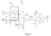
- shows a transimpedance amplifier according to the invention;
- Fig.10
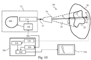
- shows a device according to the invention;
- Fig.11
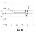
- shows, for various depths of a charged particle beam detector in a water tank, the difference between its actual depth and the depth estimated from the method of the invention.
- The figures are not drawn to scale. Generally, identical components are denoted by the same reference numerals in the figures.
- Charged particle therapy consists in sending to a target volume 25 a charged
particle beam 10. Thetarget volume 25 can be for instance a tumour.Figure 1 shows an example of asetup 150 that can be used for charged particle therapy. Means 15 send a chargedparticle beam 10, such as a proton beam, to abody 20 having atarget volume 25 to be irradiated for treatment. On opposite tofigure 1 that is not drawn to scale, thetarget volume 25 is generally much smaller than thebody 20. In the same way, means 15 are typically much larger than thebody 20. Means 15 are known by the one skilled in the art; as shown infigure 10 , it typically includes aaccelerator 300 of charged particles, such as a cyclotron, abeamline 310 to transport a chargedparticle beam 10 to thebody 20 and acontrol system 320 that controls theaccelerator 300 and thebeamline 310. To irradiate theentire target volume 25, the chargedparticle beam 10 can be scattered thanks to the use of anozzle 75 as shown infigure 1 . As a result of the scattering process, the chargedparticle beam 10 at the exit of thenozzle 75 is wide and diverging. Another possibility to irradiate theentire target volume 25 is to use a magnetically scanned beam (typically, the scanning process takes place in thenozzle 75 thanks to the use of scanning magnets). In this case, the chargedparticle beam 10 penetrating thebody 20 is more concentrate (and sometimes named pencil beam) but is typically scanned thanks to the use of varying magnetic fields that change thebeam direction 5 of the chargedparticle beam 10. The scanning process allows one to irradiate theentire target volume 25. - If one considers a charged
particle beam 10 having a given energy, the variation of the dose that is induced in abody 20 at different depths along abeam direction 5 typically has the shape offigure 2 . This figure shows an illustration of a Bragg peak (D stands for the dose, and x for the depth in the body 20). The zero value of the depth x corresponds to the entry of the chargedparticle beam 10 in thebody 20. The one skilled in the art typically defines adepth 45 up to which the chargedparticle beam 10 penetrates. Beyond thisdepth 45, the one skilled in the art typically says that the chargedparticle beam 10 is stopped. Thisdepth 45 is generally defined as the depth before which the dose falls below a given threshold after the peak, for example 90 % of the maximum dose induced in the body, which means 90 % of the dose value corresponding to the maximum of the Bragg peak. One can choose any criterion rather than 90 %. - In order to irradiate a
target volume 25 along its entire depth, one need to use a chargedparticle beam 10 that presents different energy values. This leads todifferent depths 45 up to the chargedparticle beam 10 penetrates and so to different depths at which a maximum dose is delivered. One possibility to have a chargedparticle beam 10 that is modulated in energy is to send it through an energy modulator, for instance through amodulator wheel 80. When a scattered beam is used, such amodulator wheel 80 is typically inserted in the nozzle before scattering takes place.Figure 3 shows an illustration of a modulator wheel 80: it comprises a series of segments that have absorbing materials of different thicknesses. Theblack segment 81 of themodulator wheel 80 offigure 2 corresponds to a total absorption of an incident chargedparticle beam 10. Amodulator wheel 80 typically spins at a constant speed, for instance 600 rotations per minute. The black point infigure 2 shows the place where the chargedparticle beam 10 crosses themodulator wheel 80 for a given angular position of themodulator wheel 80. As themodulator wheel 80 rotates, the chargedparticle beam 10 that points towards a given position passes through different segments having different absorbing properties. As a consequence, the chargedparticle beam 10 induces in the body 20 a series of Bragg peaks spread out in depth. By properly specifying the angular span of each segment of the range modulator, the superposition of these Bragg peaks form a flat region in the depth-dose distribution, i.e. a region having an uniform dose which is commonly referred as a spread-out Bragg peak (SOBP) by the one skilled in the art. - We now turn to detail the different steps of the method of the invention. The method of the invention aims at determining the water
equivalent depth 1 between anentrance point 30 and areference point 40. Theentrance point 30 lies on an external surface of abody 20. Two examples for thebody 20 are a phantom and a human body. Abeam direction 5 can be defined from theentrance point 30 to thereference point 40. So, thereference point 40 lies downstream theentrance point 30 along such abeam direction 5. Infigure 1 , an example ofentrance point 30 andreference point 40 is shown. Thereference point 40 lies preferably inside thebody 20 but thereference point 40 can also be located on an external surface of thebody 20 or outsidede body 20. When thereference point 40 is inside abody 20, it can be located in a natural cavity such as the rectum, or under the skin of abody 20. A chargedparticle beam detector 50 is placed at thereference point 40. Two examples of chargedparticle beam detector 50 are an ionization chamber and a semiconductor diode 110. - To carry out the method of the invention, one needs to provide means for delivering a charged
particle beam 10 in abeam direction 5 as defined above. Such means typically include a source setup (or means 15) and anozzle 75. The method of the invention works with system having a scattering or ascanning nozzle 75. In the latter case, the magnetic settings of the scanning magnets are set such that a pencil chargedparticle beam 10 points along thebeam direction 5 defined above. - Then, one has to choose a maximum 65 and minimum 70 energy value. The maximum energy value 65 is such that a charged
particle beam 10 having this maximum energy value 65 and being sent in thebeam direction 5 defined above penetrates thebody 20 from saidentrance point 30 up to at least saidreference point 40. Thedistance 45 up to a chargedparticle beam 10 penetrates has been defined above withfigure 2 . Theminimum energy value 70 is such that a chargedparticle beam 10 having thisminimum energy value 70 and being sent in thebeam direction 5 defined above penetrates thebody 20 from saidentrance point 30 and is stopped in thebody 20 before reaching thereference point 40. Thedistance 45 up to which a chargedparticle beam 10 penetrates in abody 20 has been defined above withfigure 2 . The way of determining such energy values are known by the one skilled in the art. Typically such values can be obtained from a treatment planning if one knows, at least approximately the absorption properties of thebody 20 along thebeam direction 5. - The next step of the method of the invention is to send in the beam direction 5 a charged
particle beam 10 that is time modulated in energy between the minimum 70 and maximum 65 energy value defined above. This means that the energy of the chargedparticle beam 10 has to vary in time between a minimum 70 and a maximum 65 energy value. Preferably, the time variation of the energy of the chargedparticle beam 10 is a monotically decreasing function from the maximum 65 to the minimum 70 energy value. More preferably, the time variation of the energy of the chargedparticle beam 10 is a periodic function with respect to time. To modulate the energy of a chargedparticle beam 10, one can use amodulator wheel 80 as defined above withfigure 2 . Typically, such amodulator wheel 80 rotates with a period equal to the modulator cycle 85. A typical value of the modulator cycle 85 is 100 ms. So, by using a source setup (means 15), anozzle 75 and an energy modulator, one can send in the beam direction 5 a chargedparticle beam 10 that is time modulated in energy between the minimum 70 and maximum 65 energy value. A range modulator is preferably designed for providing a flat SOBP and the minimum 70 and maximum 65 energy values are preferably chosen such that the WED to be measured (ie the reference point 40) falls in the flat SOBP region. Other types of range modulators which do not provide a flat SOBP (for example tilted SOBP) could be used for the invention as well. - A charged
particle beam 10 that is time modulated in energy induces in a body 20 a timedependent dose rate 60. When amodulator wheel 80 is used, the induced timedependent dose rate 60 is typically periodic in time with a period equal to the modulator cycle 85. At different positions lying in abody 20 and along abeam direction 5 of a chargedparticle beam 10 that is time modulated in energy, the shape of the corresponding timedependent dose rates 60 versus time changes. These different shapes are thecharacteristic patterns 105 referred notably in Hsiao-Ming Lu's publication. As a further illustration,figure 3 shows timedependent dose rates 60 calculated at twenty-one different depths along a beam direction of an energy modulated chargedparticle beam 10 when these twenty-one different depths correspond to depths in a water tank (the different curves correspond to increasing depths along the vertical arrow offigure 3 ). As shown in Hsiao-Ming Lu's publication, we observe different characteristic patterns at the different depths. - As one sends a charged
particle beam 10 that is time modulated in energy between aminimum energy value 70 and a maximum energy value 65, a timedependent dose rate 60 is induced along abeam direction 5 of this chargedparticle beam 10. If the minimum 70 and maximum 65 energy values are chosen as explained above, a chargedparticle beam detector 50 placed at thereference point 40 presents a time dependent response 55 that typically consists of stepwise structures spaced in time by the modulator cycle 85 if amodulator wheel 80 is used to produce the energy modulated chargedparticle beam 10. Similar to the timedependent dose rate 60, the time dependent responses 55 of a chargedparticle beam detector 50 present characteristic patterns when said chargedparticle beam detector 50 is placed at different positions along abeam direction 5 of a chargedparticle beam 10 that is time modulated in energy. In step e) of the method of the invention, one has to acquire a time dependent response 55 of a chargedparticle beam detector 50. The way to obtain the time dependent response 55 of a chargedparticle beam detector 50 is known from the one skilled in the art (see for instance Hsiao-Ming Lu's publication, page 1416). - The inventors have found that it is possible to relate the WED corresponding to the
distance 35 between theentrance point 30 and thereference point 40 to a value of astatistical parameter 100 of the time dependent response 55 of the chargedparticle beam detector 50, when said chargedparticle beam detector 50 is subjected to a chargedparticle beam 10 that is time modulated in energy. One can choose differentstatistical parameters 100 for determining the sought WED. An example is the skewness sk whose definition is given below. - From the time dependent response 55 of a charged
particle beam detector 50, one can define the following parameters. The sum, S, is given by:
when the time dependent response 55 is a discrete signal and by
when the time dependent response 55 is a continuous signal. In these equations, ν stands for the time dependent response 55 of the chargedparticle beam detector 50. In equation (Eq. 2), the index i 1 (resp. iN ) is the index of the first (resp. last) reading of the time dependent response 55. When the time dependent response 55 is continuous, t 1 (resp. tN ) is the time of the beginning (resp. end) of its acquisition. - The mean time of occurrence, m, of the time dependent response 55 is defined by:

when the time dependent response 55 is a discrete signal and by
when the time dependent response 55 is a continuous function, S being given by equations (Eq. 2) (discrete case) or (Eq. 3) (continuous case). The root mean square width 101, σ, is given by:
when the time dependent response 55 is a discrete signal and by
when the time dependent response 55 is a continuous function. The skewness if given by:
in the discrete case, and by
- The parameters S and m entering equations (Eq. 6) to (Eq. 9) are given by equations (Eq. 2) and (Eq. 4) in the discrete case and by (Eq. 3) and (Eq. 5) in the continuous case.
- When a
modulator wheel 80 is used, the time dependent response 55 of a chargedparticle beam detector 50 typically presentsperiodic patterns 105 separated in time by a period equal to the modulator cycle 85 as shown infigure 5 (top graph). Rather than acquiring the whole signal of the time dependent response 55 of a chargedparticle beam detector 50 before determining the value of astatistical parameter 100 such as the skewness, one skilled in the art can imagine recording its response during only one of its period by the use of synchronizing means. Then, one can apply equation (Eq. 8) or (Eq. 9) to determine the value of the skeness corresponding to said period. To increase statistics and precision, the measurement of the time dependent response can also be performed over multiple cycles of the range modulator. - As the time dependent response 55 of a charged
particle beam detector 50 subjected to an energy modulated chargedparticle beam 10 typically presents a stepwise structure, one can also isolate the different steps from the background measured level before applying equations (Eq. 8) or (Eq. 9) when the time dependent response 55 is acquired during a time longer than the modulator cycle 85. One can also calculate values of astatistical parameter 100 corresponding to different periods of the time dependent response 55, and after average these values over the different periods to obtain an average value of the chosenstatistical parameter 100. This procedure is particularly useful when the time dependent response 55 has a low signal to noise level. Alternatively, the data acquisition system can operate in synchrony with the rotation of therange modulator wheel 80 so as to obtain an accumulated time dependent response signal. -
Figure 5 shows the time dependent response 55 of a chargedparticle beam detector 50 that is a PTW Model T60012 semiconductor diode when such a diode is placed at a given depth (16.5 cm is this example) in a water phantom and subjected to a chargedparticle beam 10 that is time modulated in energy. In this example, the time dependent response 55 of the chargedparticle beam detector 50 is a time dependent negative voltage. The upper part offigure 5 shows ten patterns corresponding to ten modulator cycles 85 of themodulator wheel 80 that is used for producing the energy modulated charged particle beam. The modulator cycle 85 is equal to 100 ms in this example. The middle graph offigure 5 is a zoom of the fourth cycle whereas the lower graph shows only the beginning of the same fourth cycle. The used diode presents a disk ofarea 1 mm2 and a thickness equal to 2,5 µm (2,5 µm is the thickness of the chargedparticle beam detector 50 along abeam direction 5 of the charged particle beam 10). The diode is connected to atransimpedance amplifier 120 whose details are given below. - When a signal such as the one depicted in
figure 5 is acquired, one preferably first isolates thedifferent patterns 105 or real signals from the background level. As an example, thefirst pattern 105 can be deemed to begin when a voltage reading is more negative than a given discrimination level. After, one can take advantage of the stable mean time between eachpattern 105 that is typically equal to the modulator cycle 85 to remove occasional spurious pulses between each pattern. Knowing the value of the modulator cycle 85, one does not need to seek thesecond pattern 105 until preferably 98 ms after the first one if the modulator cycle 85 is equal to 100 ms. Continuing thus, one can identify all the tenpatterns 105 offigure 5 and determine for each of them the value of astatistical parameter 100 such as the skewness. In this case, the index i 1 (resp. i N) entering equations (Eq. 2), (Eq. 4), (Eq. 6), and (Eq. 8) is the index of the first (resp. last) reading of eachpattern 105 isolated from the background level. Knowing the different values of astatistical parameter 100 corresponding to the different patterns, one can easily calculate an averaged value of such astatistical parameter 100. Preferably, one can acquire the time dependent response 55 during a time that is longer than ten modular cycles 85 and determine more than ten values of astatistical parameter 100 before calculating an averaged value of such astatistical parameter 100. - If one acquires the time dependent response 55 of a charged
particle beam detector 50 that is positioned at different depths in a water tank and that is subjected to a chargedparticle beam 10 that is time modulated in energy, one can deduce for each depth the value of astatistical parameter 100 such as the skewness by using equations (Eq. 8) or (Eq. 9). By following this procedure, the inventors have found that such astatistical parameter 100 is smoothly and monotonically related to the depth of the chargedparticle beam detector 50 in the water tank. As a consequence, the dependence of saidstatistical parameter 100 to the depth of the chargedparticle beam detector 50 in the water tank can be well represented by a curve and such a curve can be used as acalibration curve 95. Indeed, the depths of the chargedparticle beam detector 50 with respect to the entrance point of a chargedparticle beam 10 in the water tank can be identified to WEDs. Step g) of the method of the invention aims at providing such acalibration curve 95. There are different possibilities to obtain such acalibration curve 95. One can measure the time dependent response 55 of a chargedparticle beam detector 50 that is positioned at different depths in a water tank and that is subjected to a chargedparticle beam 10 that is time modulated in energy. Or, thecalibration curve 95 can be obtained from calculations that predict the time dependent response 55 of a chargedparticle beam detector 50 placed at different depths in a water tank and exposed to an energy modulated chargedparticle beam 10. The conditions of the calibration procedure need to be the same as those used during the acquisition of the time dependent response 55 of the chargedparticle beam detector 50 placed at thereference point 40. Instead of acalibration curve 95, one could establish a calibration table. - Finally (step h) of the method of the invention), by using the
calibration curve 95 provided in step g), one can determine the WED corresponding to the value of thestatistical parameter 100 determined in step f). As an illustration and referring tofigure 6 , if the value of thestatistical parameter 100 determined in step f) is equal to a value that we name 160, the corresponding WED is equal to a value that we name 165. - Preferably, the
statistical parameter 100 that is used for determining the WED is the root mean square width 101 of the time dependent response 55 of the chargedparticle beam detector 50. The root mean square width 101 can be obtained from equations (Eq. 2), (Eq. 4), (Eq. 6) (discrete case), or (Eq. 3), (Eq. 5), (Eq. 7) (continuous case). When using such astatistical parameter 100, the region of good sensitivity is large. This is illustrated infigures 7 and 8 that show two measured calibration curves 95 corresponding to the variations of two differentstatistical parameters 100 with respect to the depth of a chargedparticle beam detector 50 in a water tank.Figure 7 (respectively 8) shows acalibration curve 95 when thestatistical parameter 100 is a skewness (respectively root mean square width 101). From these two figures, we see that the region of good sensitivity is narrower for the skewness as the slope of the curve offigure 7 is smaller than the slope of the curve offigure 8 . - Different charged
particle beam detectors 50 can be used to carry out the method of the invention. In a preferred embodiment, the chargedparticle beam detector 50 comprises a semiconductor diode 110. Ordinary semiconductor diodes 110 make good chargedparticle beam detectors 50 and present some advantages: small, rugged, and inexpensive. In yet another embodiment, the chargedparticle beam detector 50 comprises a PTW Model T60012 diode connected to atransimpedance amplifier 120. In yet another preferred embodiment, saidtransimpedance amplifier 120 has three stages. The first stage is afirst transimpedance amplifier 125 with an output of 1 mV/nA and a response time of 5 µs dominated by the feedback circuit. The next stage is an inverting voltage amplifier with a gain of 40. The output stage gain was set for a total gain of 0.5 V/nA using a precise current source. Since it is very convenient for the quiescent DC offset to be zero and stable, regulated on-board tracking 7.5 V regulators are provided. The amplifier has two DC adjustments. 'OFFSET' is set to null the output when the input is open. 'BURDEN' is set to null the output when the input is grounded through preferably 10 kΩ. Such a transimpedance amplifier, which is illustrated infigure 9 , can be connected to an oscilloscope through a coaxial cable. - The
calibration curve 95 that is used to link the value of thestatistical parameter 100 to the WED (step h of the method of the invention) of the method of the invention) can be obtained experimentally. Preferably, such an experimental determination comprises the following steps: - i. positioning said charged
particle beam detector 50 at a given position 170 in a water or water-equivalent calibration phantom 115; - ii. sending to said charged
particle beam detector 50 the chargedparticle beam 10 that is time modulated in energy between said minimum 70 and said maximum 65 energy value; - iii. acquiring a time dependent response 55 of said charged
particle beam detector 50; - iv. determining a value of said
statistical parameter 100 from said time dependent response 55; - v. determining a water
equivalent depth 1, said waterequivalent depth 1 being the distance between the entrance point of said chargedparticle beam 10 in said calibration phantom 115 and said given position 170; - vi. repeating steps i. to v. n times, n being an integer larger than one;
- vii. establishing a
calibration curve 95 that relates the values of thestatistical parameter 100 determined in step iv. and the waterequivalent depth 1 determined in step v.. - When the
statistical parameter 100 is a root mean square width 101, thecalibration curve 95 of step vii is preferably a cubic polynomial curve. Adding higher order terms does not improve the fit quality and the precision significantly. - In another embodiment, the charged
particle beam detector 50 comprises an array of semiconductor diodes 110 placed transversally with respect to the chargedparticle beam 10. Typically, the semiconductor diodes 110 are then spread over a few cm2, preferably on a flex circuit attached to a rectal balloon. By using such an array, one can deduce for each semiconductor diode 110 the value of astatistical parameter 100, preferably a root mean square width 101 by using the method of the invention described above. By comparing the different values corresponding to the different semiconductor diodes 110, one can evaluate the spatial variation of the WED in thebody 20 or obtain a mean value over the area covered by the array of semiconductor diodes 110. - According to a second aspect of the invention, the inventors propose to use a device for determining the WED between an
entrance point 30 and areference point 40. Such a device is shown infigure 10 with other elements. The device of the invention comprises a unit such as acomputer 200 with a set of subunits or software modules that implement various steps of the method of the invention. Thecomputer 200 can be an ordinary, single processor personal computer. The different software modules described below can be included in different computers or different units rather than in asingle computer 200. Thecomputer 200 also includes an internal memory (not shown infigure 10 ) for storing computer program instructions which control how a processing unit within thecomputer 200 accepts, transforms, and outputs data. The internal memory includes both a volatile and a non-volatile portion. Those skilled in the art will recognize that the internal memory can be supplemented with computer memory media, such as compact disk, flash memory cards, magnetic disc drives. - Before the
computer 200 can determine aWED 1 of a chargedparticle beam 10 that is sent to abody 20, a minimum 70 and a maximum 65 energy value are provided to means 15 (or source setup) by atreatment planning 280 as an example. More precisely, these energy values (70, 65) are sent to acontrol system 320 of the source setup. The source setup (or means 15) is able to send a chargedparticle beam 10 that is time modulated in energy between these minimum 70 and maximum 65 energy values along abeam trajectory 5. The minimum 70 and maximum 65 energy values have been defined above. A chargedparticle beam 10 with the maximum (respectively minimum) energy value 65 (respectively 70) penetrates thebody 20 along abeam direction 5 till adepth 45 that is equal or larger (respectively smaller) than thereference distance 35. Thedepth 45 till which a chargedparticle beam 10 of a given energy penetrates has been defined above withfigure 2 . - The device of the invention comprises a charged
particle beam detector 50 that is placed at thereference point 40. When the chargedparticle beam detector 50 is subjected to a chargedparticle beam 10 that is time modulated in energy between the minimum 70 and the maximum 65 energy values, it presents a time dependent response 55. This time dependent response 55 can be measured by specific electronic components known by those skilled in the art. If one uses an ionization chamber for the chargedparticle beam detector 50, one can use for instance a scanning system that samples, in time, the ionization current generated in an ionization chamber.Means 230 of the device of the invention allows one to acquire the time dependent response 55 of the chargedparticle beam detector 50. - From this time dependent response 55, means 240 (a subunit of the computer 200) of the device of the invention determines a value of a
statistical parameter 100, for instance the skewness that is given by equations (Eq. 8) for a discrete signal and by equation (Eq. 9) when the signal is continuous. Preferably thestatistical parameter 100 is a root mean square width 101 given by equations (Eq. 6) or (Eq. 7). Thedevice 200 comprises preferably a library of calibration curves 95 obtained for various beam modulations, i.e. for various values ofminimum 75 and maximum 65 energies. As discussed above, each of these calibration curves 95 expresses a relationship between values of astatistical parameter 100 and WEDs. Asubunit 250 selects acalibration curve 95 from the library that is in correspondence with the minimum and maximum energy values. Means 260 (another subunit of the computer 200) can eventually determine from this selectedcalibration curve 95 the WED corresponding to thestatistical parameter 100 of the time dependent response 55. This result can optionally be sent to ascreen 270. - In a preferred embodiment, the charged
particle beam detector 50 comprises a semiconductor diode 110. In another embodiment, such a semiconductor diode 110 is connected to the input of atransimpedance amplifier 120 instead of using a usual current integrator. The time dependent response 55 is then measured at the ouput of thetransimpedance amplifier 120. In another preferred embodiment, such atransimpedance amplifier 120 has three stages (seefigure 9 ): afirst transimpedance amplifier 125, an inverting voltage amplifier with a gain ranging between 35 and 45, and an output stage whose gain is set to obtain a total gain ranging between 0.4 V / nA and 0.6 V / nA. In yet another preferred embodiment, thefirst stage 125 of such atransimpedance amplifier 120 has an output of 1 mV/nA and a response time of 5 µs; the second stage (inverting voltage amplifier) has a gain of 40, and the output stage is set for a total gain of 0.5 V/nA. The chargedparticle beam detector 50 preferably comprises an array of semiconductor diodes 110 placed transversally with respect to the chargedparticle beam 10. - According to a last aspect of the invention, a program is proposed. This program allows one to determine a water equivalent depth between an
entrance point 30 and areference point 40, saidentrance point 30 lying on an external surface of abody 20, saidreference point 40 being a point at which a chargedparticle beam detector 50 is placed, said program comprising : - a software module 430 for acquiring a time dependent response 55 of said charged
particle beam detector 50; - a software module 440 for determining a value of a
statistical parameter 100 of said time dependent response 55; - a software module 450 for loading a
pre-determined calibration curve 95 expressing a relationship between values of saidstatistical parameter 100 and waterequivalent depths 1; - a software module 460 for determining from said
calibration curve 95 the waterequivalent depth 1 corresponding to the value of thestatistical parameter 100 of the time dependent response 55 of the chargedparticle beam detector 50 placed at thereference point 40. - We now present some results obtained with the method of the invention. As a reminder, two examples of
calibration curve 95 are shown infigure 7 and 8 that are now detailed. Aproton beam 10 that is modulated in energy has been sent to a water tank. The time dependent response 55 of a PTW Model T60012 diode that is subjected to such a chargedparticle beam 10 and that is positioned at different depths in a water tank has been recorded during ten modulator cycles 85. At each depth and for each modulator cycles 85, the value of astatistical parameter 100 is determined. Infigure 7 , the statistical parameter is the skewness given by equation (Eq. 8) whereasfigure 8 corresponds to the case where the statistical parameter is a root mean square width 101 given by equation (Eq. 6). Then, an averaged value of these two statistical parameters 100 (denoted by 〈sk〉10 infigure 7 and by 〈σt 〉10 infigure 8 ) can be calculated for each depth by taking the average of the values of the correspondingstatistical parameters 100 determined for each modulator cycle 85. The circles infigure 7 and 8 show the averaged values of thesestatistical parameters 100 at different depths. Infigure 8 , the continuous curve is a fit corresponding to a cubic polynomial. This figure shows the smooth and monotonic dependence of the root meansquare width 100 with depth (or WED). - To obtain the experimental calibration curves 95 of
figure 7 and 8 , the inventors have used a PTW Model T60012 diode connected to atransimpedance amplifier 120 as the one shown infigure 9 . Using the same chargedparticle beam detector 50 connected to thesame transimpedance amplifier 120, the inventors have carried out in a water tank three series of measurements that we name A, C and D. At the beginning of each series, the chargedparticle beam detector 50 was driven to 19 cm and subsequently moved upstream to avoid backlash, if any. For each series, the chargedparticle beam detector 50 was subjected at different known depths to an energy modulatedproton beam 10, and its time dependence response 55 was measured and recorded during ten modulator cycles. For each depth and each modulator cycle, the value of a root mean square width 101 was determined by using equations (Eq. 2), (Eq. 4), and (Eq. 6). Then, for each depth, an averaged value of root mean square width 101 was determined by taking the average of the individual values of root mean square widths 101 corresponding to the ten modulator cycles. By using the calibration curve offigure 8 , the inventors have determined the corresponding WEDs or depths in the water tank. Series A corresponds to a preliminary exploration (one point of measurement); series C corresponds to different positions of the chargedparticle beam detector 50 separated by 1 cm steps; series D relates to measurements in 0.5 mm steps.Figure 11 compares the differences between the actual depth of the chargedparticle beam detector 50 and the depth estimated from the measured time dependence responses 55 of the chargedparticle beam detector 50 by using the method of the invention (open squares : series A, open circles : series C, and filled circles : series D). The root mean square scatter of these nineteen points about zero is 0.026 cm (dashed lines infigure 11 ); such a value represents the precision of the method of the invention that is better than the 1 mm of the Lu's method. With more than ten patterns for determining the value of the root mean square width 101 corresponding to each depth in the water tank, one could expect to increase the precision of the method of the invention. - By using the method of the invention, one can verify the particle range in-vivo, and possibly modify the parameters of a treatment planning after such a determination of the WED.
- The present invention has been described in terms of specific embodiments, which are illustrative of the invention and not to be construed as limiting. More generally, it will be appreciated by persons skilled in the art that the present invention is not limited by what has been particularly shown and/or described hereinabove. The invention resides in each and every novel characteristic feature and each and every combination of characteristic features. Reference numerals in the claims do not limit their protective scope. Use of the verbs "to comprise", "to include", "to be composed of", or any other variant, as well as their respective conjugations, does not exclude the presence of elements other than those stated. Use of the article "a", "an" or "the" preceding an element does not exclude the presence of a plurality of such elements.
- Summarized, the invention may also be described as follows. Method for determining a water
equivalent depth 1 between anentrance point 30 and areference point 40. The method comprises the following steps: sending to a chargedparticle beam detector 50 placed at areference point 40 within or beyond a body 20 a chargedparticle beam 10 whose energy is modulated between a minimum 70 and maximum 65 energy value; acquiring the time dependent response 55 of said chargedparticle beam detector 50; determining from said time dependent response 55 a value of astatistical parameter 100; providing acalibration curve 95 expressing a relationship between values of saidstatistical parameter 100 and waterequivalent depths 1; finally, extracting from thiscalibration curve 95 the waterequivalent depth 1 corresponding to the value of thestatistical parameter 100 determined from the time dependent response 55 of the chargedparticle beam detector 50 placed at thereference point 40.
Claims (14)
- A method for determining a water equivalent depth (1) between an entrance point (30) and a reference point (40), said entrance point (30) lying on an external surface of a body (20), said reference point (40) being a point at which a charged particle beam detector (50) is placed,
said method comprising the steps of :a) providing means for delivering a charged particle beam (10) to said body (20) in a beam direction (5) defined from said entrance point (30) to said reference point (40);b) choosing a maximum energy value (65) such that a charged particle beam (10) having said maximum energy value (65) and being sent in said beam direction (5) penetrates the body (20) from said entrance point (30) up to at least said reference point (40);c) choosing a minimum energy value (70) such that a charged particle beam (10) having said minimum energy value (70) and being sent in said beam direction (5) penetrates the body (20) from said entrance point (30) and is stopped in said body (20) before reaching said reference point (40);d) sending in said beam direction (5) a charged particle beam (10) that is time modulated in energy between said minimum energy value (70) and said maximum energy value (65);e) acquiring a time dependent response (55) of the charged particle beam detector (50);characterized in that said method further comprises the steps of :f) determining a value of a statistical parameter (100) of said time dependent response (55);g) providing a pre-determined calibration curve (95) expressing a relationship between values of said statistical parameter (100) and water equivalent depths (1);h) determining from said calibration curve (95) the water equivalent depth (1) between the entrance point (30) and the reference point (40) corresponding to the value of the statistical parameter (100) determined in step f). - A method according to claim 1 characterized in that said statistical parameter (100) is a root mean square width (101) of said time dependent response (55).
- A method according to claim 1 or 2 characterized in that said reference point (40) is positioned inside said body (20).
- A method according to claim 1 or 2 characterized in that said reference point (40) is positioned outside said body (20).
- A method according to any of the previous claims characterized in that the charged particle beam detector (50) comprises a semiconductor diode (110) for detecting the charged particle beam (10).
- A method according to claim 5 characterized in that said semiconductor diode (110) is connected to an input of a transimpedance amplifier (120), and in that said time dependent response (55) is measured at an output of said transimpedance amplifier (120).
- A method according to claim 6 characterized in that said transimpedance amplifier (120) has three stages:- a first transimpendance amplifier (125),- an inverting voltage amplifier with a gain ranging between 35 and 45,- an output stage whose gain is set to obtain a gain between the input and the output of said transimpedance amplifier (120) ranging between 0.4 V / nA and 0.6 V / nA.
- A method according to any of the previous claims characterized in that the pre-determined calibration curve (95) is obtained from the following steps:i. positioning said charged particle beam detector (50) at a given position (170) in a water or water-equivalent calibration phantom (115);ii. sending to said charged particle beam detector (50) the charged particle beam (10) that is time modulated in energy between said minimum (70) and said maximum (65) energy value;iii. acquiring a time dependent response (55) of said charged particle beam detector (50);iv. determining a value of said statistical parameter (100) from said time dependent response (55);v. determining a water equivalent depth (1), said water equivalent depth (1) being the distance between the entrance point of said charged particle beam (10) in said calibration phantom (115) and said given position (170);vi. repeating steps i. to v. n times, n being an integer larger than one;vii. establishing a calibration curve (95) that relates the values of the statistical parameter (100) determined in step iv. and the water equivalent depth (1) determined in step v..
- A method according to any of the previous claims characterized in that the charged particle beam detector (50) comprises an array of semiconductor diodes (110) placed transversally with respect to the charged particle beam (10).
- A device for determining a water equivalent depth (1) between an entrance point (30) and a reference point (40), said entrance point (30) lying on an external surface of a body (20), said device comprising :- a charged particle beam detector (50) that is placed at the reference point (40);- means (230) for acquiring a time dependent response (55) of said charged particle beam detector (50);
characterized in that said device further comprises :- means (240) for determining a value of a statistical parameter (100) of said time dependent response (55);- means (250) for loading a pre-determined calibration curve (95) expressing a relationship between values of said statistical parameter (100) and water equivalent depths (1);- means (260) for determining from said calibration curve (95) the water equivalent depth (1) corresponding to the value of the statistical parameter (100) of the time dependent response (55) of the charged particle beam detector (50) placed at the reference point (40). - A device according to claim 10 characterized in that the charged particle
beam detector (50) comprises a semiconductor diode (110). - A device according to claim 11 characterized in that said semiconductor
diode (110) is connected to an input of a transimpedance amplifier (120), and in that said time dependent response (55) is measured at an output of said transimpedance amplifier (120). - A device according to claim 12 characterized in that the charged particle beam detector (50) comprises an array of semiconductor diodes (110) placed transversally with respect to the charged particle beam (10).
- A program for determining a water equivalent depth (1) between an entrance point (30) and a reference point (40), said entrance point (30) lying on an external surface of a body (20), said reference point (40) being a point at which a charged particle beam detector (50) is placed, said program comprising :- a software module (430) for acquiring a time dependent response (55) of said charged particle beam detector (50);
characterized in that said program further comprises :- a software module (440) for determining a value of a statistical parameter (100) of said time dependent response (55);- a software module (450) for loading a pre-determined calibration curve (95) expressing a relationship between values of said statistical parameter (100) and water equivalent depths (1);- a software module (460) for determining from said calibration curve (95) the water equivalent depth (1) corresponding to the value of the statistical parameter (100) of the time dependent response (55) of the charged particle beam detector (50) placed at the reference point (40).
Priority Applications (1)
| Application Number | Priority Date | Filing Date | Title |
|---|---|---|---|
| EP20110157125 EP2497535B1 (en) | 2011-03-07 | 2011-03-07 | Water equivalent depth measurement |
Applications Claiming Priority (1)
| Application Number | Priority Date | Filing Date | Title |
|---|---|---|---|
| EP20110157125 EP2497535B1 (en) | 2011-03-07 | 2011-03-07 | Water equivalent depth measurement |
Publications (2)
| Publication Number | Publication Date |
|---|---|
| EP2497535A1 true EP2497535A1 (en) | 2012-09-12 |
| EP2497535B1 EP2497535B1 (en) | 2014-05-07 |
Family
ID=43875206
Family Applications (1)
| Application Number | Title | Priority Date | Filing Date |
|---|---|---|---|
| EP20110157125 Not-in-force EP2497535B1 (en) | 2011-03-07 | 2011-03-07 | Water equivalent depth measurement |
Country Status (1)
| Country | Link |
|---|---|
| EP (1) | EP2497535B1 (en) |
-
2011
- 2011-03-07 EP EP20110157125 patent/EP2497535B1/en not_active Not-in-force
Non-Patent Citations (3)
| Title |
|---|
| HSIAO-MING LU: "A potential method for in vivo range verification in proton therapy treatment", PHYS. MED. BIOL., vol. 53, 2008, pages 1413 - 1424 |
| HSIAO-MING LU: "A potential method for in vivo range verification in proton therapy treatment", PHYS. MED. BIOL., vol. 53, no. 5, 19 February 2008 (2008-02-19), pages 1413 - 1424, XP002633969 * |
| PHYS. MED. BIOL., vol. 53, 2008, pages 1413 - 1424 |
Also Published As
| Publication number | Publication date |
|---|---|
| EP2497535B1 (en) | 2014-05-07 |
Similar Documents
| Publication | Publication Date | Title |
|---|---|---|
| US9480862B2 (en) | Water equivalent depth measurement for providing a continuous calibration range based on discrete measurements | |
| US9364688B2 (en) | Method and apparatus for monitoring the range of a particle beam | |
| US5627367A (en) | Radiation beam calibrater | |
| US8357907B2 (en) | Method and device for real-time measurement of a local dose upon bombardment of a target by hadrons by means of prompt gamma rays | |
| EP2977083B1 (en) | An apparatus for particle therapy verification | |
| US9517358B2 (en) | Upstream direct x-ray detection | |
| WO2018125435A1 (en) | Determination of radiation collimator component position | |
| WO2014179430A2 (en) | System design and method for verifying 3d dosimetric imaging of charged particles in media | |
| Espinoza et al. | The feasibility study and characterization of a two‐dimensional diode array in “magic phantom” for high dose rate brachytherapy quality assurance | |
| US10874880B2 (en) | Method for the automation of the dose calibration, reconstruction and verification of complex radiotherapy treatments, integrated into one environment, and system for implementing same | |
| JP2018514356A (en) | Calibration of radiation detector | |
| JP6588980B2 (en) | Dose distribution calculation device, particle beam therapy device, and dose distribution calculation method | |
| JP6009765B2 (en) | Fast scan of target area | |
| CN114206439A (en) | Device and method for monitoring the treatment of a body part of a patient with particles | |
| EP2950119B1 (en) | System and method for verifying a particle beam | |
| CN103127623A (en) | Method of online authentication of accelerator out-beam accuracy in radiation therapy | |
| TWI773031B (en) | Calibration device, treatment planning device and calibration method | |
| CN108525139A (en) | The setting method of neutron beam detecting system and neutron beam detecting system | |
| Guardiola et al. | Preliminary microdosimetric measurements with ultra-thin 3D silicon detectors of a 62 MeV proton beam | |
| Gottschalk et al. | Water equivalent path length measurement in proton radiotherapy using time resolved diode dosimetry | |
| EP2497535B1 (en) | Water equivalent depth measurement | |
| Park et al. | Comparison of knife-edge and multi-slit camera for proton beam range verification by Monte Carlo simulation | |
| Han et al. | Time‐resolved dosimetry with pencil‐beam scanning for quality assurance/quality control in particle therapy | |
| Kowalik et al. | Calculation and measurement of doses in the surface layers of a phantom when using Tomotherapy | |
| Sakaria et al. | Picket fence test of Agility MLCs using linac log data |
Legal Events
| Date | Code | Title | Description |
|---|---|---|---|
| PUAI | Public reference made under article 153(3) epc to a published international application that has entered the european phase |
Free format text: ORIGINAL CODE: 0009012 |
|
| AK | Designated contracting states |
Kind code of ref document: A1 Designated state(s): AL AT BE BG CH CY CZ DE DK EE ES FI FR GB GR HR HU IE IS IT LI LT LU LV MC MK MT NL NO PL PT RO RS SE SI SK SM TR |
|
| AX | Request for extension of the european patent |
Extension state: BA ME |
|
| 17P | Request for examination filed |
Effective date: 20130312 |
|
| GRAP | Despatch of communication of intention to grant a patent |
Free format text: ORIGINAL CODE: EPIDOSNIGR1 |
|
| INTG | Intention to grant announced |
Effective date: 20130524 |
|
| GRAP | Despatch of communication of intention to grant a patent |
Free format text: ORIGINAL CODE: EPIDOSNIGR1 |
|
| INTG | Intention to grant announced |
Effective date: 20131213 |
|
| GRAS | Grant fee paid |
Free format text: ORIGINAL CODE: EPIDOSNIGR3 |
|
| GRAA | (expected) grant |
Free format text: ORIGINAL CODE: 0009210 |
|
| AK | Designated contracting states |
Kind code of ref document: B1 Designated state(s): AL AT BE BG CH CY CZ DE DK EE ES FI FR GB GR HR HU IE IS IT LI LT LU LV MC MK MT NL NO PL PT RO RS SE SI SK SM TR |
|
| REG | Reference to a national code |
Ref country code: GB Ref legal event code: FG4D |
|
| REG | Reference to a national code |
Ref country code: AT Ref legal event code: REF Ref document number: 666132 Country of ref document: AT Kind code of ref document: T Effective date: 20140515 |
|
| REG | Reference to a national code |
Ref country code: IE Ref legal event code: FG4D |
|
| REG | Reference to a national code |
Ref country code: NL Ref legal event code: T3 Ref country code: DE Ref legal event code: R096 Ref document number: 602011006670 Country of ref document: DE Effective date: 20140618 |
|
| REG | Reference to a national code |
Ref country code: AT Ref legal event code: MK05 Ref document number: 666132 Country of ref document: AT Kind code of ref document: T Effective date: 20140507 |
|
| REG | Reference to a national code |
Ref country code: LT Ref legal event code: MG4D |
|
| PG25 | Lapsed in a contracting state [announced via postgrant information from national office to epo] |
Ref country code: GR Free format text: LAPSE BECAUSE OF FAILURE TO SUBMIT A TRANSLATION OF THE DESCRIPTION OR TO PAY THE FEE WITHIN THE PRESCRIBED TIME-LIMIT Effective date: 20140808 Ref country code: FI Free format text: LAPSE BECAUSE OF FAILURE TO SUBMIT A TRANSLATION OF THE DESCRIPTION OR TO PAY THE FEE WITHIN THE PRESCRIBED TIME-LIMIT Effective date: 20140507 Ref country code: CY Free format text: LAPSE BECAUSE OF FAILURE TO SUBMIT A TRANSLATION OF THE DESCRIPTION OR TO PAY THE FEE WITHIN THE PRESCRIBED TIME-LIMIT Effective date: 20140507 Ref country code: NO Free format text: LAPSE BECAUSE OF FAILURE TO SUBMIT A TRANSLATION OF THE DESCRIPTION OR TO PAY THE FEE WITHIN THE PRESCRIBED TIME-LIMIT Effective date: 20140807 Ref country code: LT Free format text: LAPSE BECAUSE OF FAILURE TO SUBMIT A TRANSLATION OF THE DESCRIPTION OR TO PAY THE FEE WITHIN THE PRESCRIBED TIME-LIMIT Effective date: 20140507 Ref country code: IS Free format text: LAPSE BECAUSE OF FAILURE TO SUBMIT A TRANSLATION OF THE DESCRIPTION OR TO PAY THE FEE WITHIN THE PRESCRIBED TIME-LIMIT Effective date: 20140907 |
|
| PG25 | Lapsed in a contracting state [announced via postgrant information from national office to epo] |
Ref country code: AT Free format text: LAPSE BECAUSE OF FAILURE TO SUBMIT A TRANSLATION OF THE DESCRIPTION OR TO PAY THE FEE WITHIN THE PRESCRIBED TIME-LIMIT Effective date: 20140507 Ref country code: SE Free format text: LAPSE BECAUSE OF FAILURE TO SUBMIT A TRANSLATION OF THE DESCRIPTION OR TO PAY THE FEE WITHIN THE PRESCRIBED TIME-LIMIT Effective date: 20140507 Ref country code: PL Free format text: LAPSE BECAUSE OF FAILURE TO SUBMIT A TRANSLATION OF THE DESCRIPTION OR TO PAY THE FEE WITHIN THE PRESCRIBED TIME-LIMIT Effective date: 20140507 Ref country code: ES Free format text: LAPSE BECAUSE OF FAILURE TO SUBMIT A TRANSLATION OF THE DESCRIPTION OR TO PAY THE FEE WITHIN THE PRESCRIBED TIME-LIMIT Effective date: 20140507 Ref country code: RS Free format text: LAPSE BECAUSE OF FAILURE TO SUBMIT A TRANSLATION OF THE DESCRIPTION OR TO PAY THE FEE WITHIN THE PRESCRIBED TIME-LIMIT Effective date: 20140507 Ref country code: LV Free format text: LAPSE BECAUSE OF FAILURE TO SUBMIT A TRANSLATION OF THE DESCRIPTION OR TO PAY THE FEE WITHIN THE PRESCRIBED TIME-LIMIT Effective date: 20140507 Ref country code: HR Free format text: LAPSE BECAUSE OF FAILURE TO SUBMIT A TRANSLATION OF THE DESCRIPTION OR TO PAY THE FEE WITHIN THE PRESCRIBED TIME-LIMIT Effective date: 20140507 |
|
| PG25 | Lapsed in a contracting state [announced via postgrant information from national office to epo] |
Ref country code: PT Free format text: LAPSE BECAUSE OF FAILURE TO SUBMIT A TRANSLATION OF THE DESCRIPTION OR TO PAY THE FEE WITHIN THE PRESCRIBED TIME-LIMIT Effective date: 20140908 |
|
| PG25 | Lapsed in a contracting state [announced via postgrant information from national office to epo] |
Ref country code: EE Free format text: LAPSE BECAUSE OF FAILURE TO SUBMIT A TRANSLATION OF THE DESCRIPTION OR TO PAY THE FEE WITHIN THE PRESCRIBED TIME-LIMIT Effective date: 20140507 Ref country code: RO Free format text: LAPSE BECAUSE OF FAILURE TO SUBMIT A TRANSLATION OF THE DESCRIPTION OR TO PAY THE FEE WITHIN THE PRESCRIBED TIME-LIMIT Effective date: 20140507 Ref country code: DK Free format text: LAPSE BECAUSE OF FAILURE TO SUBMIT A TRANSLATION OF THE DESCRIPTION OR TO PAY THE FEE WITHIN THE PRESCRIBED TIME-LIMIT Effective date: 20140507 Ref country code: CZ Free format text: LAPSE BECAUSE OF FAILURE TO SUBMIT A TRANSLATION OF THE DESCRIPTION OR TO PAY THE FEE WITHIN THE PRESCRIBED TIME-LIMIT Effective date: 20140507 Ref country code: SK Free format text: LAPSE BECAUSE OF FAILURE TO SUBMIT A TRANSLATION OF THE DESCRIPTION OR TO PAY THE FEE WITHIN THE PRESCRIBED TIME-LIMIT Effective date: 20140507 |
|
| REG | Reference to a national code |
Ref country code: DE Ref legal event code: R097 Ref document number: 602011006670 Country of ref document: DE |
|
| PLBE | No opposition filed within time limit |
Free format text: ORIGINAL CODE: 0009261 |
|
| STAA | Information on the status of an ep patent application or granted ep patent |
Free format text: STATUS: NO OPPOSITION FILED WITHIN TIME LIMIT |
|
| 26N | No opposition filed |
Effective date: 20150210 |
|
| PG25 | Lapsed in a contracting state [announced via postgrant information from national office to epo] |
Ref country code: IT Free format text: LAPSE BECAUSE OF FAILURE TO SUBMIT A TRANSLATION OF THE DESCRIPTION OR TO PAY THE FEE WITHIN THE PRESCRIBED TIME-LIMIT Effective date: 20140507 |
|
| REG | Reference to a national code |
Ref country code: DE Ref legal event code: R097 Ref document number: 602011006670 Country of ref document: DE Effective date: 20150210 |
|
| PG25 | Lapsed in a contracting state [announced via postgrant information from national office to epo] |
Ref country code: SI Free format text: LAPSE BECAUSE OF FAILURE TO SUBMIT A TRANSLATION OF THE DESCRIPTION OR TO PAY THE FEE WITHIN THE PRESCRIBED TIME-LIMIT Effective date: 20140507 |
|
| PG25 | Lapsed in a contracting state [announced via postgrant information from national office to epo] |
Ref country code: LU Free format text: LAPSE BECAUSE OF FAILURE TO SUBMIT A TRANSLATION OF THE DESCRIPTION OR TO PAY THE FEE WITHIN THE PRESCRIBED TIME-LIMIT Effective date: 20150307 Ref country code: MC Free format text: LAPSE BECAUSE OF FAILURE TO SUBMIT A TRANSLATION OF THE DESCRIPTION OR TO PAY THE FEE WITHIN THE PRESCRIBED TIME-LIMIT Effective date: 20140507 |
|
| REG | Reference to a national code |
Ref country code: CH Ref legal event code: PL |
|
| REG | Reference to a national code |
Ref country code: IE Ref legal event code: MM4A |
|
| PG25 | Lapsed in a contracting state [announced via postgrant information from national office to epo] |
Ref country code: LI Free format text: LAPSE BECAUSE OF NON-PAYMENT OF DUE FEES Effective date: 20150331 Ref country code: CH Free format text: LAPSE BECAUSE OF NON-PAYMENT OF DUE FEES Effective date: 20150331 Ref country code: IE Free format text: LAPSE BECAUSE OF NON-PAYMENT OF DUE FEES Effective date: 20150307 |
|
| REG | Reference to a national code |
Ref country code: FR Ref legal event code: PLFP Year of fee payment: 6 |
|
| PG25 | Lapsed in a contracting state [announced via postgrant information from national office to epo] |
Ref country code: MT Free format text: LAPSE BECAUSE OF FAILURE TO SUBMIT A TRANSLATION OF THE DESCRIPTION OR TO PAY THE FEE WITHIN THE PRESCRIBED TIME-LIMIT Effective date: 20140507 |
|
| REG | Reference to a national code |
Ref country code: FR Ref legal event code: PLFP Year of fee payment: 7 |
|
| PG25 | Lapsed in a contracting state [announced via postgrant information from national office to epo] |
Ref country code: SM Free format text: LAPSE BECAUSE OF FAILURE TO SUBMIT A TRANSLATION OF THE DESCRIPTION OR TO PAY THE FEE WITHIN THE PRESCRIBED TIME-LIMIT Effective date: 20140507 Ref country code: BG Free format text: LAPSE BECAUSE OF FAILURE TO SUBMIT A TRANSLATION OF THE DESCRIPTION OR TO PAY THE FEE WITHIN THE PRESCRIBED TIME-LIMIT Effective date: 20140507 Ref country code: HU Free format text: LAPSE BECAUSE OF FAILURE TO SUBMIT A TRANSLATION OF THE DESCRIPTION OR TO PAY THE FEE WITHIN THE PRESCRIBED TIME-LIMIT; INVALID AB INITIO Effective date: 20110307 |
|
| PG25 | Lapsed in a contracting state [announced via postgrant information from national office to epo] |
Ref country code: TR Free format text: LAPSE BECAUSE OF FAILURE TO SUBMIT A TRANSLATION OF THE DESCRIPTION OR TO PAY THE FEE WITHIN THE PRESCRIBED TIME-LIMIT Effective date: 20140507 |
|
| REG | Reference to a national code |
Ref country code: FR Ref legal event code: PLFP Year of fee payment: 8 |
|
| PGFP | Annual fee paid to national office [announced via postgrant information from national office to epo] |
Ref country code: NL Payment date: 20180326 Year of fee payment: 8 Ref country code: GB Payment date: 20180327 Year of fee payment: 8 |
|
| PGFP | Annual fee paid to national office [announced via postgrant information from national office to epo] |
Ref country code: FR Payment date: 20180326 Year of fee payment: 8 Ref country code: BE Payment date: 20180327 Year of fee payment: 8 |
|
| PG25 | Lapsed in a contracting state [announced via postgrant information from national office to epo] |
Ref country code: MK Free format text: LAPSE BECAUSE OF FAILURE TO SUBMIT A TRANSLATION OF THE DESCRIPTION OR TO PAY THE FEE WITHIN THE PRESCRIBED TIME-LIMIT Effective date: 20140507 |
|
| PGFP | Annual fee paid to national office [announced via postgrant information from national office to epo] |
Ref country code: DE Payment date: 20180328 Year of fee payment: 8 |
|
| PG25 | Lapsed in a contracting state [announced via postgrant information from national office to epo] |
Ref country code: AL Free format text: LAPSE BECAUSE OF FAILURE TO SUBMIT A TRANSLATION OF THE DESCRIPTION OR TO PAY THE FEE WITHIN THE PRESCRIBED TIME-LIMIT Effective date: 20140507 |
|
| REG | Reference to a national code |
Ref country code: DE Ref legal event code: R119 Ref document number: 602011006670 Country of ref document: DE |
|
| REG | Reference to a national code |
Ref country code: NL Ref legal event code: MM Effective date: 20190401 |
|
| GBPC | Gb: european patent ceased through non-payment of renewal fee |
Effective date: 20190307 |
|
| REG | Reference to a national code |
Ref country code: BE Ref legal event code: MM Effective date: 20190331 |
|
| PG25 | Lapsed in a contracting state [announced via postgrant information from national office to epo] |
Ref country code: NL Free format text: LAPSE BECAUSE OF NON-PAYMENT OF DUE FEES Effective date: 20190401 Ref country code: GB Free format text: LAPSE BECAUSE OF NON-PAYMENT OF DUE FEES Effective date: 20190307 Ref country code: DE Free format text: LAPSE BECAUSE OF NON-PAYMENT OF DUE FEES Effective date: 20191001 |
|
| PG25 | Lapsed in a contracting state [announced via postgrant information from national office to epo] |
Ref country code: FR Free format text: LAPSE BECAUSE OF NON-PAYMENT OF DUE FEES Effective date: 20190331 Ref country code: BE Free format text: LAPSE BECAUSE OF NON-PAYMENT OF DUE FEES Effective date: 20190331 |