EP2497452A1 - Motorized wheelchair - Google Patents
Motorized wheelchair Download PDFInfo
- Publication number
- EP2497452A1 EP2497452A1 EP11157165A EP11157165A EP2497452A1 EP 2497452 A1 EP2497452 A1 EP 2497452A1 EP 11157165 A EP11157165 A EP 11157165A EP 11157165 A EP11157165 A EP 11157165A EP 2497452 A1 EP2497452 A1 EP 2497452A1
- Authority
- EP
- European Patent Office
- Prior art keywords
- wheelchair
- support assembly
- frame
- battery support
- power drive
- Prior art date
- Legal status (The legal status is an assumption and is not a legal conclusion. Google has not performed a legal analysis and makes no representation as to the accuracy of the status listed.)
- Granted
Links
Images


Classifications
-
- A—HUMAN NECESSITIES
- A61—MEDICAL OR VETERINARY SCIENCE; HYGIENE
- A61G—TRANSPORT, PERSONAL CONVEYANCES, OR ACCOMMODATION SPECIALLY ADAPTED FOR PATIENTS OR DISABLED PERSONS; OPERATING TABLES OR CHAIRS; CHAIRS FOR DENTISTRY; FUNERAL DEVICES
- A61G5/00—Chairs or personal conveyances specially adapted for patients or disabled persons, e.g. wheelchairs
- A61G5/04—Chairs or personal conveyances specially adapted for patients or disabled persons, e.g. wheelchairs motor-driven
-
- A—HUMAN NECESSITIES
- A61—MEDICAL OR VETERINARY SCIENCE; HYGIENE
- A61G—TRANSPORT, PERSONAL CONVEYANCES, OR ACCOMMODATION SPECIALLY ADAPTED FOR PATIENTS OR DISABLED PERSONS; OPERATING TABLES OR CHAIRS; CHAIRS FOR DENTISTRY; FUNERAL DEVICES
- A61G5/00—Chairs or personal conveyances specially adapted for patients or disabled persons, e.g. wheelchairs
- A61G5/04—Chairs or personal conveyances specially adapted for patients or disabled persons, e.g. wheelchairs motor-driven
- A61G5/041—Chairs or personal conveyances specially adapted for patients or disabled persons, e.g. wheelchairs motor-driven having a specific drive-type
- A61G5/045—Rear wheel drive
-
- A—HUMAN NECESSITIES
- A61—MEDICAL OR VETERINARY SCIENCE; HYGIENE
- A61G—TRANSPORT, PERSONAL CONVEYANCES, OR ACCOMMODATION SPECIALLY ADAPTED FOR PATIENTS OR DISABLED PERSONS; OPERATING TABLES OR CHAIRS; CHAIRS FOR DENTISTRY; FUNERAL DEVICES
- A61G5/00—Chairs or personal conveyances specially adapted for patients or disabled persons, e.g. wheelchairs
- A61G5/10—Parts, details or accessories
- A61G5/1078—Parts, details or accessories with shock absorbers or other suspension arrangements between wheels and frame
-
- Y—GENERAL TAGGING OF NEW TECHNOLOGICAL DEVELOPMENTS; GENERAL TAGGING OF CROSS-SECTIONAL TECHNOLOGIES SPANNING OVER SEVERAL SECTIONS OF THE IPC; TECHNICAL SUBJECTS COVERED BY FORMER USPC CROSS-REFERENCE ART COLLECTIONS [XRACs] AND DIGESTS
- Y10—TECHNICAL SUBJECTS COVERED BY FORMER USPC
- Y10S—TECHNICAL SUBJECTS COVERED BY FORMER USPC CROSS-REFERENCE ART COLLECTIONS [XRACs] AND DIGESTS
- Y10S180/00—Motor vehicles
- Y10S180/907—Motorized wheelchairs
-
- Y—GENERAL TAGGING OF NEW TECHNOLOGICAL DEVELOPMENTS; GENERAL TAGGING OF CROSS-SECTIONAL TECHNOLOGIES SPANNING OVER SEVERAL SECTIONS OF THE IPC; TECHNICAL SUBJECTS COVERED BY FORMER USPC CROSS-REFERENCE ART COLLECTIONS [XRACs] AND DIGESTS
- Y10—TECHNICAL SUBJECTS COVERED BY FORMER USPC
- Y10S—TECHNICAL SUBJECTS COVERED BY FORMER USPC CROSS-REFERENCE ART COLLECTIONS [XRACs] AND DIGESTS
- Y10S180/00—Motor vehicles
- Y10S180/908—Motor vehicles with short wheelbase
Definitions
- the present invention relates to a motorized wheelchair. More particularly, the present invention relates to a construction of the chassis of a motorized wheelchair, which is as compact as possible.
- Power drive or motorized wheelchairs in general are known in the art to provide motorized mobility to persons confined to a wheelchair.
- Such power drive wheelchairs conventionally comprise a relatively sturdy wheelchair frame supported on wheels for rolling movement, in combination with one or more batteries for supplying electrical power to one or more electrical motors coupled to the drive wheels of the wheels.
- the wheelchair frame further carries a seat module including a seat and a backrest as well as armrests.
- motorized wheelchairs require large batteries to have a long drive range. These large batteries lead to enlarge the width of the wheelchair. Moreover, if one needs a faster motorized wheelchair, it is also imperative to use larger motors. Considering that the motors are generally positioned at the same level as the batteries in a conventional motorized wheelchair, it is often difficult to propose a motorized wheelchair possessing a high speed and a long drive range which has also a small width. The width of the wheelchair is important for the user, since it has a direct impact on how easy it is to drive through narrow doors.
- EP 2 226 048 A1 reveals motorized wheelchairs in which the motors are fixed on swing arms located left and right of batteries, said swing arms being pivotally connected on the wheelchair frame. To avoid contact between the swing arms and the batteries during the wheelchair's motion, a space of about 1 to 1,5 cm between them is provided. This additional space is clearly an obstacle to reduce the lateral extension of the wheelchair.
- a first objective of the present invention is to provide a motorized wheelchair that is as compact as possible.
- a second objective of the present invention is to provide a motorized wheelchair in which the rear wheel suspension is improved.
- the present invention provides a motorized wheelchair comprising :
- situations and directions of elements of the wheelchair of the present invention are determined by the perspective of a user seated in the wheelchair. Accordingly, the left side of the wheelchair corresponds to the left side of Figures 2 and 4 or to the right side of Figures 1 and 3 .
- the situations or directions “up” or “top” and “down” or “bottom”, “rear” or “back” and “front”, “behind” and “in front”, “distal” and “proximal”, “lateral” and “central” follow the same rule.
- the present invention relates to a motorized wheelchair.
- the motorized wheelchair may be a dismountable wheelchair, meaning that at least a part of the wheelchair can be reversibly removed from the wheelchair. In this way, it is possible to remove at least one part, for example for the purpose of repairing the part or in order to arrange the wheelchair in a more space-saving manner, for example for storage and/or transport of the wheelchair.
- Figures 1 and 2 show a base of a conventional motorized wheelchair 1 with the seat, armrests and legrests of the wheelchair being removed for the reasons of clarity. Any one selected from the seat, the armrests, the legrests and/or the battery boxes may be demountable and remountable.
- the wheelchair of Figures 1 and 2 comprises a frame 2', said frame being formed by a main, U-shaped frame element 11', the open end of the U being oriented towards the front.
- a horizontal frame element 12' is provided in a front area of the frame 2'.
- Said wheelchair 1 comprises also a pair of left and right rear wheels 3'a, 3'b and a pair of left and right front castor wheel 4'a, 4'b.
- a pair of left and right power drive assemblies 5'a, 5'b, each assembly comprising a motor and a gear box assembly, are provided in order to propel the left and right rear wheels 3'a, 3'b, respectively.
- the castor wheels 4'a, 4'b are pivotally connected at the free ends of the U-shape element 11'.
- the rear wheels 3'a, 3'b are rotatably coupled to the gearbox assembly of the power drive assemblies 5'a, 5'b, respectively.
- the power drive assemblies 5'a, 5'b are supported by left and right swing arms 6'a, 6'b, respectively, said swing arms 6'a, 6'b being pivotally connected to the U-shape element 11' at their front ends.
- the free lateral space separating said swing arms 6'a, 6'b and said power drive assemblies 5'a, 5'b is configured to lodge at least one battery box 13'.
- the battery box 13' is supported by left and right longitudinal rails 7'a, 7'b, extending parallely along each lateral side of the battery box 13' and fixed on the frame 2' by left and right connection plates 8'a and 8'b.
- the left, respectively right, side of the battery box 13' is separated from the gear box of the left, respectively right, power drive assembly 5'a, respectively 5'b, by a distance d'.
- This distance d' is necessary to prevent that a contact between the battery box 13' and the gear box occurs during the wheelchair's motion.
- the distance d' is generally chosen so as to be comprised between 1 cm and 1,5 cm.
- the width of the frame 2' encompasses up to 3 cm of useless space. The aim of the invention is therefore to provide a new construction reducing this useless space.
- FIG 3 shows a base of a motorized wheelchair 10 according to the invention with the seat, armrests and legrests of the wheelchair being removed for the reasons of clarity. Any one selected from the seat, the armrests, the legrests and/or the battery boxes may be dismountable and remountable.
- the wheelchair 10 comprises a frame 2, said frame being formed by a main, U-shaped frame element 11, the open end of the U being oriented towards the front, each leg of the U defining the longitudinal direction of the wheelchair 10 and the bottom of the U defining the lateral direction of the wheelchair 10, said lateral direction being perpendicular to said longitudinal direction.
- a horizontal frame element 12 is provided in a front area of the frame 2.
- Said wheelchair 10 comprises also a pair of left and right rear wheels 3a, 3b and a pair of left and right front castor wheel 4a, 4b.
- a pair of left and right power drive assemblies 5a, 5b each assembly comprising a motor 14a, 14b and a gear box assembly 15a, 15b, are provided in order to propel the left and right rear wheels 3a, 3b, respectively.
- Each power drive assembly 5a, 5b comprises also a forked structure at its rear extremity, said forked structure rotatably supporting an anti-tip wheel 20a, 20b.
- the castor wheels 4a, 4b are pivotally connected at the free ends of the U-shape element 11.
- the rear wheels 3a, 3b are rotatably coupled to the gearbox assemblies 15a, 15b of the left and right power drive assemblies 5a, 5b, respectively.
- the gear box assemblies 15a, 15b of the left and right power drive assemblies 5a, 5b are fixedly and directly connected to the lateral sides of a battery support assembly 6 by screws or other similar means of connection.
- Said battery support assembly 6 is configured to support at least one battery box 13.
- said battery support assembly 6 defines approximately a parallelepipedical housing, said housing being defined, at its lateral sides, by left and right connecting plates 6a, 6b, on which is connected the left and right power drive assemblies 5a, 5b, respectively, at its lower side, by a plate 6c, supporting the lower side of said battery box 13, at its upper side, by three parallel crossbars 6d1, 6d2, 6d3, respectively positioned at the left, right and central part of said housing, said crossbars 6d1 and 6d2 extending above said left and right connecting plates 6a, 6b, respectively, and, at its rear side, by a rear plate 6f, which is fixedly connected to said crossbars 6d1, 6d2, 6d3 by three screws 17a, 17b, 17c, respectively, said rear plate 6f supporting at its rear side a socket 18 which is electrically connected to the battery box 13.
- the battery support assembly 6 comprises also a front connecting plate 6e, which is pivotally connected to a bracket 7, so that said battery support assembly 6 can pivot around a longitudinal axis YY'.
- the axis YY' is enclosed in a vertical plane of symmetry for the wheelchair 10.
- the connection means connecting said connecting plate 6e and said bracket 7 comprise a cylindrical element 8 fixedly connected to said connecting plate 6e and extending in the axial direction YY' from the front side of said plate 6e, said cylindrical element 8 being disposed, at least partially, inside a cylindrical hole 7c formed in the center part of said bracket 7, the internal diameter of said hole 7c being higher than the external diameter of said cylindrical element 8.
- This configuration permits to lodge in said hole 7c, between said element 8 and said bracket 7, a first and second annular bushing 8a, 8b, introduced inside said hole 7c from the rear and front sides, respectively, said element 8, said bushings 8a, 8b and said bracket 7 being connected together by a screw 8d engaging a threaded hole of said element 8 and acting against an end washer 8c which is in contact with said bushing 8b.
- Said bracket 7 is also configured to pivotally connect said battery support assembly 6 to the wheelchair frame 2, so that said battery support assembly 6 can pivot around a lateral axis XX'.
- said axis XX' is approximately perpendicular to said axis YY'.
- said bracket 7 comprises at its left and right upper sides a left and right tubular connecting elements 7a, 7b, respectively, said elements 7a, 7b extending in the axial direction XX' and being in contact at their lateral ends with a pair of connecting plates 17a, 18a and 17b, 18b, respectively, of the wheelchair frame 2.
- Said connecting plates 17a, 18a, 17b, 18b are each perforated with a hole aligned in the axial direction XX' with the axial apertures of said elements 7a, 7b so that two left and right bolts 16a, 16b permit the pivoting connection between said bracket 7 and said wheelchair frame 2.
- the battery support assembly 6 is connected to the underside of each leg of the U-shape frame element 11 by at least two shock absorbers 9a, 9b so as to restrain the pivoting movement of said battery support assembly 6 around the first axis XX' and/or the second axis YY'.
- said shock absorbers 9a, 9b consist in rubber springs, the lower side of said rubber springs 9a, 9b being supported by the central part of two U-shape elements 19a, 19b fixedly connected to the crossbars 6d1 and 6d2, respectively.
- Figure 4 is a rear assembled view of the wheelchair base of Figure 3 .
- the left, respectively right, connecting plate 6a, respectively 6b, of the battery support assembly 6 is separated from the gear box of the left, respectively right, power drive assembly 5a, respectively 5b, by a distance d.
- This distance d depends only on the connecting means used to connect said power assemblies 5a, 5b to said battery support assembly 6.
- the distance d between said battery support assembly 6 and said power drive assemblies 5a, 5b does not vary during the wheelchair's motion, because these two elements are fixedly connected together. Therefore, the distance d is generally less than 0,5 cm, and preferably less than 0,1 cm.
Landscapes
- Health & Medical Sciences (AREA)
- Life Sciences & Earth Sciences (AREA)
- Animal Behavior & Ethology (AREA)
- General Health & Medical Sciences (AREA)
- Public Health (AREA)
- Veterinary Medicine (AREA)
- Handcart (AREA)
- Carriages For Children, Sleds, And Other Hand-Operated Vehicles (AREA)
Abstract
- a frame (2), defining a longitudinal direction and a lateral direction perpendicular to said longitudinal direction,
- a battery support assembly (6) for supporting at least one battery box (13), said battery support assembly (6) being connected to said frame (2),
- first and second power drive assemblies (5a, 5b) disposed on each lateral side of the wheelchair (10), each assemblies (5a, 5b) comprising a motor (14a, 14b) and a gearbox assembly (15a, 15b),
- first and second rear wheels (3a, 3b) respectively driven by said first and second power drive assemblies (5a, 5b),
wherein said first and second power drive assemblies (5a, 5b) are directly fixed on the battery support assembly (6).
Description
- The present invention relates to a motorized wheelchair. More particularly, the present invention relates to a construction of the chassis of a motorized wheelchair, which is as compact as possible.
- Power drive or motorized wheelchairs in general are known in the art to provide motorized mobility to persons confined to a wheelchair. Such power drive wheelchairs conventionally comprise a relatively sturdy wheelchair frame supported on wheels for rolling movement, in combination with one or more batteries for supplying electrical power to one or more electrical motors coupled to the drive wheels of the wheels. The wheelchair frame further carries a seat module including a seat and a backrest as well as armrests.
- One of the problems associated with motorized wheelchairs is that they require large batteries to have a long drive range. These large batteries lead to enlarge the width of the wheelchair. Moreover, if one needs a faster motorized wheelchair, it is also imperative to use larger motors. Considering that the motors are generally positioned at the same level as the batteries in a conventional motorized wheelchair, it is often difficult to propose a motorized wheelchair possessing a high speed and a long drive range which has also a small width. The width of the wheelchair is important for the user, since it has a direct impact on how easy it is to drive through narrow doors.
- In the state of art,
EP 2 226 048 A1 - Therefore, a first objective of the present invention is to provide a motorized wheelchair that is as compact as possible.
- A second objective of the present invention is to provide a motorized wheelchair in which the rear wheel suspension is improved.
- In an aspect, the present invention provides a motorized wheelchair comprising :
- a frame, defining a longitudinal direction and a lateral direction perpendicular to said longitudinal direction,
- a battery support assembly for supporting at least one battery box, said battery support assembly being connected to said frame,
- first and second power drive assemblies disposed on each lateral side of the wheelchair, each assemblies comprising a motor and a gearbox assembly,
- first and second rear wheels respectively driven by said first and second power drive assemblies,
- Further aspects and preferred embodiments are provided in the appended claims.
- The wheelchair of the present invention will be described in further detail further below, when useful with reference to the attached drawings, which show an exemplary wheelchair according to the invention.
-
Figure 1 is a front perspective view showing the base of a conventional motorized wheelchair, from which the seat construction, including armrests and legrests, and the battery boxes were removed. -
Figure 2 is a rear view of the same wheelchair base as shown inFigure 1 , in which the battery boxes are replaced inside the base. -
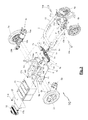
Figure 3 is an exploded front perspective view showing the base of a wheelchair according to an embodiment of the invention, from which the seat construction, including armrests and legrests, is removed. -
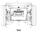
Figure 4 is a rear assembled view of the wheelchair base ofFigure 3 . - For the purpose of the present specification, situations and directions of elements of the wheelchair of the present invention are determined by the perspective of a user seated in the wheelchair. Accordingly, the left side of the wheelchair corresponds to the left side of
Figures 2 and4 or to the right side ofFigures 1 and3 . The situations or directions "up" or "top" and "down" or "bottom", "rear" or "back" and "front", "behind" and "in front", "distal" and "proximal", "lateral" and "central" follow the same rule. - The present invention relates to a motorized wheelchair. The motorized wheelchair may be a dismountable wheelchair, meaning that at least a part of the wheelchair can be reversibly removed from the wheelchair. In this way, it is possible to remove at least one part, for example for the purpose of repairing the part or in order to arrange the wheelchair in a more space-saving manner, for example for storage and/or transport of the wheelchair.
-
Figures 1 and2 show a base of a conventionalmotorized wheelchair 1 with the seat, armrests and legrests of the wheelchair being removed for the reasons of clarity. Any one selected from the seat, the armrests, the legrests and/or the battery boxes may be demountable and remountable. The wheelchair ofFigures 1 and2 comprises a frame 2', said frame being formed by a main, U-shaped frame element 11', the open end of the U being oriented towards the front. A horizontal frame element 12' is provided in a front area of the frame 2'. Saidwheelchair 1 comprises also a pair of left and right rear wheels 3'a, 3'b and a pair of left and right front castor wheel 4'a, 4'b. A pair of left and right power drive assemblies 5'a, 5'b, each assembly comprising a motor and a gear box assembly, are provided in order to propel the left and right rear wheels 3'a, 3'b, respectively. The castor wheels 4'a, 4'b are pivotally connected at the free ends of the U-shape element 11'. The rear wheels 3'a, 3'b are rotatably coupled to the gearbox assembly of the power drive assemblies 5'a, 5'b, respectively. The power drive assemblies 5'a, 5'b are supported by left and right swing arms 6'a, 6'b, respectively, said swing arms 6'a, 6'b being pivotally connected to the U-shape element 11' at their front ends. As best shown onFigure 2 , the free lateral space separating said swing arms 6'a, 6'b and said power drive assemblies 5'a, 5'b is configured to lodge at least one battery box 13'. The battery box 13' is supported by left and right longitudinal rails 7'a, 7'b, extending parallely along each lateral side of the battery box 13' and fixed on the frame 2' by left and right connection plates 8'a and 8'b. When the battery box 13' is in its position of use, one can see onFigure 2 that the left, respectively right, side of the battery box 13' is separated from the gear box of the left, respectively right, power drive assembly 5'a, respectively 5'b, by a distance d'. This distance d' is necessary to prevent that a contact between the battery box 13' and the gear box occurs during the wheelchair's motion. The distance d' is generally chosen so as to be comprised between 1 cm and 1,5 cm. Thus, in thisconventional wheelchair 1, the width of the frame 2' encompasses up to 3 cm of useless space. The aim of the invention is therefore to provide a new construction reducing this useless space. -
Figure 3 shows a base of amotorized wheelchair 10 according to the invention with the seat, armrests and legrests of the wheelchair being removed for the reasons of clarity. Any one selected from the seat, the armrests, the legrests and/or the battery boxes may be dismountable and remountable. Thewheelchair 10 comprises aframe 2, said frame being formed by a main,U-shaped frame element 11, the open end of the U being oriented towards the front, each leg of the U defining the longitudinal direction of thewheelchair 10 and the bottom of the U defining the lateral direction of thewheelchair 10, said lateral direction being perpendicular to said longitudinal direction. Ahorizontal frame element 12 is provided in a front area of theframe 2. Saidwheelchair 10 comprises also a pair of left and rightrear wheels front castor wheel power drive assemblies motor gear box assembly rear wheels power drive assembly anti-tip wheel castor wheels U-shape element 11. Therear wheels gearbox assemblies power drive assemblies power drive assemblies battery support assembly 6 by screws or other similar means of connection. Saidbattery support assembly 6 is configured to support at least onebattery box 13. In the illustrated embodiment, saidbattery box 13 having an approximately parallelepipedical form, saidbattery support assembly 6 defines approximately a parallelepipedical housing, said housing being defined, at its lateral sides, by left and right connectingplates power drive assemblies plate 6c, supporting the lower side of saidbattery box 13, at its upper side, by three parallel crossbars 6d1, 6d2, 6d3, respectively positioned at the left, right and central part of said housing, said crossbars 6d1 and 6d2 extending above said left and right connectingplates rear plate 6f, which is fixedly connected to said crossbars 6d1, 6d2, 6d3 by threescrews rear plate 6f supporting at its rear side asocket 18 which is electrically connected to thebattery box 13. At its front end, thebattery support assembly 6 comprises also a front connecting plate 6e, which is pivotally connected to a bracket 7, so that saidbattery support assembly 6 can pivot around a longitudinal axis YY'. In the illustrated embodiment, the axis YY' is enclosed in a vertical plane of symmetry for thewheelchair 10. The connection means connecting said connecting plate 6e and said bracket 7 comprise a cylindrical element 8 fixedly connected to said connecting plate 6e and extending in the axial direction YY' from the front side of said plate 6e, said cylindrical element 8 being disposed, at least partially, inside a cylindrical hole 7c formed in the center part of said bracket 7, the internal diameter of said hole 7c being higher than the external diameter of said cylindrical element 8. This configuration permits to lodge in said hole 7c, between said element 8 and said bracket 7, a first and secondannular bushing 8a, 8b, introduced inside said hole 7c from the rear and front sides, respectively, said element 8, saidbushings 8a, 8b and said bracket 7 being connected together by a screw 8d engaging a threaded hole of said element 8 and acting against anend washer 8c which is in contact with said bushing 8b. Said bracket 7 is also configured to pivotally connect saidbattery support assembly 6 to thewheelchair frame 2, so that saidbattery support assembly 6 can pivot around a lateral axis XX'. In the illustrated embodiment, said axis XX' is approximately perpendicular to said axis YY'. Thus, said bracket 7 comprises at its left and right upper sides a left and righttubular connecting elements elements plates wheelchair frame 2. Said connectingplates elements right bolts wheelchair frame 2. Finally, thebattery support assembly 6 is connected to the underside of each leg of theU-shape frame element 11 by at least twoshock absorbers battery support assembly 6 around the first axis XX' and/or the second axis YY'. In the illustrated embodiment, saidshock absorbers rubber springs U-shape elements -
Figure 4 is a rear assembled view of the wheelchair base ofFigure 3 . One can see onFigure 4 that the left, respectively right, connectingplate 6a, respectively 6b, of thebattery support assembly 6 is separated from the gear box of the left, respectively right,power drive assembly 5a, respectively 5b, by a distance d. This distance d depends only on the connecting means used to connect saidpower assemblies battery support assembly 6. Indeed, contrary to the conventional wheelchair ofFigures 1 and2 , the distance d between saidbattery support assembly 6 and saidpower drive assemblies
Claims (14)
- A motorized wheelchair (10) comprising:- a frame (2), defining a longitudinal direction and a lateral direction perpendicular to said longitudinal direction,- a battery support assembly (6) for supporting at least one battery box (13), said battery support assembly (6) being connected to said frame (2),- first and second power drive assemblies (5a, 5b) disposed on each lateral side of the wheelchair (10), each assemblies (5a, 5b) comprising a motor (14a, 14b) and a gearbox assembly (15a, 15b),- first and second rear wheels (3a, 3b) respectively driven by said first and second power drive assemblies (5a, 5b),wherein said first and second power drive assemblies (5a, 5b) are directly fixed on the battery support assembly (6).
- The wheelchair (10) of the preceding claim wherein the distance (d) separating said first and/or second power drive assemblies (5a, 5b) and said battery support assembly (6) in the lateral direction is less than 0,5 cm, preferably less than 0,1 cm, and more preferably approximately null.
- The wheelchair (10) of the preceding claim 1 or claim 2, wherein said battery support assembly (6) is pivotally connected to said frame (2) by first connecting means (7), so that said battery support assembly (6) can pivot around a first longitudinal axis (XX').
- The wheelchair (10) of the preceding claim, wherein said battery support assembly (6) is pivotally connected to said first connecting means (7) by second connecting means (8), so that said battery support assembly (6) can pivot around a second lateral axis (YY').
- The wheelchair (10) of the preceding claim, wherein said second axis (YY') being approximately perpendicular to said first axis (XX').
- The wheelchair (10) of any one of the claims 3 to 5, wherein said first connecting means comprises a bracket (7) provided at its left and right upper sides with a left and right tubular connecting elements (7a, 7b), respectively, said tubular connecting elements (7a, 7b) extending along the first longitudinal axis (XX') and being in contact at their lateral ends with a pair of connecting plates (17a, 18a; 17b, 18b), respectively, of the frame (2), said connecting plates (17a, 18a; 17b, 18b) being each perforated with a hole aligned in the axial direction (XX') with the axial apertures of said tubular connecting elements (7a, 7b) so that two left and right bolts (16a, 16b) permit the pivoting connection between said bracket (7) and said frame (2).
- The wheelchair (10) of any one of the claims 3 to 5, wherein said first connecting means comprises a bracket provided at its upper side with at least one cylindrical connecting element, said cylindrical connecting element extending along the first longitudinal axis (XX') and being pivotally connected to the frame (2), in particular by a ball bearing or a roller bearing, so as to permit the pivoting connection between said bracket and said frame (2).
- The wheelchair (10) of the preceding claim 6 or claim 7, wherein said second connecting means comprises a cylindrical element (8) fixedly connected to the battery support assembly (6) and extending in the axial direction (YY') from the front side of said battery support assembly (6), said cylindrical element (8) being disposed, at least partially, and rotatably movable inside a cylindrical hole (7c) formed in the center part of said bracket (7).
- The wheelchair (10) of any one of the claims 3 to 8, wherein said battery support assembly (6) is connected to the underside of said frame (2) by at least one shock absorber (9a, 9b) so as to restrain the pivoting movement of said battery support assembly (6) around said first and/or said second axis (XX', YY').
- The wheelchair (10) of the preceding claim, wherein said battery support assembly (6) is connected to the underside of said frame (2) by at least two shock absorbers (9a, 9b) disposed at each lateral side of said frame (2).
- The wheelchair (10) of the preceding claim 9 or claim 10, wherein said shock absorbers consist in springs (9a, 9b) providing three degrees of freedom.
- The wheelchair (10) of the preceding claim, wherein said shock absorbers consist in rubber spring (9a, 9b).
- The wheelchair (10) of any one of the preceding claims, wherein the frame (2) is formed by a main, U-shaped frame element (11), the open end of the U being oriented towards the front, each leg of the U defining the longitudinal direction of the wheelchair (10) and the bottom of the U defining the lateral direction of the wheelchair (10).
- The wheelchair (10) of any one of the claims 6 to 13, wherein said battery support assembly (6) defines approximately a parallelepipedical housing, said housing being defined, at its lateral sides, by left and right connecting plates (6a, 6b), on which is connected the left and right power drive assemblies (5a, 5b), respectively, at its lower side, by a plate (6c), supporting the lower side of said battery box (13), at its upper side, by three parallel crossbars (6d1, 6d2, 6d3), respectively positioned at the left, right and central part of said housing, said left and right crossbars (6d1, 6d2) extending above said left and right connecting plates (6a, 6b), respectively, at its rear side, by a rear plate (6f), which is fixedly connected to said crossbars (6d1 6d2, 6d3) by three screws (17a, 17b, 17c), respectively, and at its front side, by a front connecting plate (6e), which is pivotally connected to the bracket (7).
Priority Applications (6)
| Application Number | Priority Date | Filing Date | Title |
|---|---|---|---|
| DK11157165.9T DK2497452T3 (en) | 2011-03-07 | 2011-03-07 | Motorized wheelchair |
| ES11157165.9T ES2500941T3 (en) | 2011-03-07 | 2011-03-07 | Motorized wheelchair |
| PT111571659T PT2497452E (en) | 2011-03-07 | 2011-03-07 | Motorized wheelchair |
| EP11157165.9A EP2497452B1 (en) | 2011-03-07 | 2011-03-07 | Motorized wheelchair |
| CA2770765A CA2770765A1 (en) | 2011-03-07 | 2012-03-06 | Motorized wheelchair |
| US13/413,839 US8820454B2 (en) | 2011-03-07 | 2012-03-07 | Motorized wheelchair |
Applications Claiming Priority (1)
| Application Number | Priority Date | Filing Date | Title |
|---|---|---|---|
| EP11157165.9A EP2497452B1 (en) | 2011-03-07 | 2011-03-07 | Motorized wheelchair |
Publications (2)
| Publication Number | Publication Date |
|---|---|
| EP2497452A1 true EP2497452A1 (en) | 2012-09-12 |
| EP2497452B1 EP2497452B1 (en) | 2014-06-11 |
Family
ID=44317671
Family Applications (1)
| Application Number | Title | Priority Date | Filing Date |
|---|---|---|---|
| EP11157165.9A Active EP2497452B1 (en) | 2011-03-07 | 2011-03-07 | Motorized wheelchair |
Country Status (6)
| Country | Link |
|---|---|
| US (1) | US8820454B2 (en) |
| EP (1) | EP2497452B1 (en) |
| CA (1) | CA2770765A1 (en) |
| DK (1) | DK2497452T3 (en) |
| ES (1) | ES2500941T3 (en) |
| PT (1) | PT2497452E (en) |
Cited By (1)
| Publication number | Priority date | Publication date | Assignee | Title |
|---|---|---|---|---|
| EP3656364A1 (en) | 2018-11-22 | 2020-05-27 | Invacare International GmbH | Motorized wheelchair chassis and motorized wheelchair comprising the same |
Families Citing this family (6)
| Publication number | Priority date | Publication date | Assignee | Title |
|---|---|---|---|---|
| US10468645B2 (en) * | 2015-01-29 | 2019-11-05 | Ford Global Technologies, Llc | Vehicle frame mounted high voltage battery assembly |
| WO2018064808A1 (en) * | 2016-10-08 | 2018-04-12 | 浙江国自机器人技术有限公司 | Unmanned transfer robot and chassis thereof |
| WO2019075374A1 (en) * | 2017-10-12 | 2019-04-18 | Sunrise Medical (Us) Llc | Wheelchair having an adjustable base |
| CN109925134B (en) * | 2017-12-15 | 2023-10-03 | 东莞市全乐电动科技有限公司 | Hand push wheelchair propeller |
| CN112274333B (en) * | 2020-10-14 | 2021-07-30 | 青岛柒有医疗科技有限公司 | Novel medical electric shifting vehicle |
| EP4302741B1 (en) | 2022-07-07 | 2025-01-29 | Permobil AB | Powered midwheel drive wheelchair with standing capability |
Citations (5)
| Publication number | Priority date | Publication date | Assignee | Title |
|---|---|---|---|---|
| EP0829247A2 (en) * | 1996-09-13 | 1998-03-18 | Hank G. Torres | Wheelchair seat |
| EP0927551A1 (en) * | 1997-06-06 | 1999-07-07 | Misawahomu Kabushiki Kaisha | Wheelchair |
| US6375209B1 (en) * | 1997-10-06 | 2002-04-23 | Kurt Manufacturing Company | Powered wheelchair |
| EP1582189A1 (en) * | 2004-03-30 | 2005-10-05 | Otto Bock HealthCare GmbH | Dismountable electric wheelchair |
| EP2226048A1 (en) | 2009-03-02 | 2010-09-08 | Invacare International Sàrl | Motorized wheelchair |
Family Cites Families (15)
| Publication number | Priority date | Publication date | Assignee | Title |
|---|---|---|---|---|
| US4140192A (en) * | 1977-11-02 | 1979-02-20 | The Spastics Society | Wheelchairs |
| US4825971A (en) * | 1985-01-14 | 1989-05-02 | Bernstein Lawrence A | Universal wheeled chair |
| SE465015B (en) * | 1987-06-22 | 1991-07-15 | Inm Industriteknik Ab | ELECTRICALLY DISABLED VEHICLE CARES IN SPECIAL CHILD |
| US5156226A (en) * | 1988-10-05 | 1992-10-20 | Everest & Jennings, Inc. | Modular power drive wheelchair |
| US4967864A (en) * | 1988-10-05 | 1990-11-06 | Everest & Jennings, Inc. | Modular power drive wheelchair |
| US5996716A (en) * | 1996-10-25 | 1999-12-07 | Orthofab | Adjustable wheelchair |
| US6095271A (en) * | 1997-10-06 | 2000-08-01 | Sunrise Medical Hhg Inc. | Battery mounting system for a powered wheelchair |
| JP3451426B2 (en) * | 1998-09-11 | 2003-09-29 | 日進医療器株式会社 | Wheelchair assembly structure |
| US20010013437A1 (en) * | 2000-02-12 | 2001-08-16 | Husted Royce H. | Removable battery for powered chairs and the like |
| US20020088657A1 (en) * | 2001-01-11 | 2002-07-11 | Vincent Brett | Method and apparatus for motorizing a wheelchair |
| EP1441401A1 (en) * | 2003-01-25 | 2004-07-28 | Pihsiang Machinery MFG. Co., Ltd. | Battery module structure of electrical vehicle |
| US7398842B2 (en) * | 2005-05-24 | 2008-07-15 | Fontecchio Bruce E | Articulating quad-drive wheelchair |
| US8037953B2 (en) * | 2005-10-17 | 2011-10-18 | Pride Mobility Products Corporation | Powered wheelchair having a side-access battery compartment |
| WO2008036279A2 (en) * | 2006-09-18 | 2008-03-27 | Pride Mobility Products Corporation | Powered wheelchair having an articulating beam and related methods of use |
| DE112007003518T5 (en) * | 2007-05-23 | 2010-04-15 | 4Power4 Sprl | Steering mechanism, especially for short vehicles |
-
2011
- 2011-03-07 EP EP11157165.9A patent/EP2497452B1/en active Active
- 2011-03-07 DK DK11157165.9T patent/DK2497452T3/en active
- 2011-03-07 ES ES11157165.9T patent/ES2500941T3/en active Active
- 2011-03-07 PT PT111571659T patent/PT2497452E/en unknown
-
2012
- 2012-03-06 CA CA2770765A patent/CA2770765A1/en not_active Abandoned
- 2012-03-07 US US13/413,839 patent/US8820454B2/en active Active
Patent Citations (5)
| Publication number | Priority date | Publication date | Assignee | Title |
|---|---|---|---|---|
| EP0829247A2 (en) * | 1996-09-13 | 1998-03-18 | Hank G. Torres | Wheelchair seat |
| EP0927551A1 (en) * | 1997-06-06 | 1999-07-07 | Misawahomu Kabushiki Kaisha | Wheelchair |
| US6375209B1 (en) * | 1997-10-06 | 2002-04-23 | Kurt Manufacturing Company | Powered wheelchair |
| EP1582189A1 (en) * | 2004-03-30 | 2005-10-05 | Otto Bock HealthCare GmbH | Dismountable electric wheelchair |
| EP2226048A1 (en) | 2009-03-02 | 2010-09-08 | Invacare International Sàrl | Motorized wheelchair |
Cited By (2)
| Publication number | Priority date | Publication date | Assignee | Title |
|---|---|---|---|---|
| EP3656364A1 (en) | 2018-11-22 | 2020-05-27 | Invacare International GmbH | Motorized wheelchair chassis and motorized wheelchair comprising the same |
| US11123242B2 (en) | 2018-11-22 | 2021-09-21 | Invacare International Gmbh | Motorized wheelchair chassis and motorized wheelchair comprising the same |
Also Published As
| Publication number | Publication date |
|---|---|
| PT2497452E (en) | 2014-09-16 |
| US20120228042A1 (en) | 2012-09-13 |
| CA2770765A1 (en) | 2012-09-07 |
| ES2500941T3 (en) | 2014-10-01 |
| EP2497452B1 (en) | 2014-06-11 |
| US8820454B2 (en) | 2014-09-02 |
| DK2497452T3 (en) | 2014-09-15 |
Similar Documents
| Publication | Publication Date | Title |
|---|---|---|
| EP2497452B1 (en) | Motorized wheelchair | |
| US7516984B2 (en) | Jointed mechanism of electric wheelchair | |
| CN103068352B (en) | Electric mid-wheel drive wheelchair | |
| US7735591B2 (en) | Powered wheelchair having an articulating beam and related methods of use | |
| US6530445B1 (en) | Variable wheelbase personal mobility vehicle | |
| CA2813891C (en) | Anti-tip and suspension systems for wheelchairs | |
| US7100716B2 (en) | Modular wheel chair | |
| CA2394417A1 (en) | Wheel chair with monocoque-type body | |
| CN106214367B (en) | The comprehensive wheelchair of adjustment height with shock-absorbing function | |
| AU2009100221A4 (en) | A cantilevered arm suspension system for use with mid wheel drive power wheelchairs | |
| CN220980208U (en) | Six-wheel cushioning base structure and wheelchair thereof | |
| EP3351228B1 (en) | Modular wheel assembly for a wheelchair | |
| EP3395313A1 (en) | Cognitive robot for rehabilitation and transport | |
| CN109789047B (en) | Chassis for mobility aids and electric wheelchairs | |
| CN112224317B (en) | Scooter chassis and scooter | |
| EP4186483A1 (en) | Wheelchair or handcycle with rear suspension | |
| CN117231673A (en) | A six-wheel cushioning base structure and its wheelchair | |
| EP0911011A1 (en) | Electrically driven wheelchair | |
| HK1152858B (en) | Wheelchair suspension |
Legal Events
| Date | Code | Title | Description |
|---|---|---|---|
| PUAI | Public reference made under article 153(3) epc to a published international application that has entered the european phase |
Free format text: ORIGINAL CODE: 0009012 |
|
| AK | Designated contracting states |
Kind code of ref document: A1 Designated state(s): AL AT BE BG CH CY CZ DE DK EE ES FI FR GB GR HR HU IE IS IT LI LT LU LV MC MK MT NL NO PL PT RO RS SE SI SK SM TR |
|
| AX | Request for extension of the european patent |
Extension state: BA ME |
|
| 17P | Request for examination filed |
Effective date: 20130215 |
|
| 17Q | First examination report despatched |
Effective date: 20130422 |
|
| GRAP | Despatch of communication of intention to grant a patent |
Free format text: ORIGINAL CODE: EPIDOSNIGR1 |
|
| INTG | Intention to grant announced |
Effective date: 20140213 |
|
| GRAS | Grant fee paid |
Free format text: ORIGINAL CODE: EPIDOSNIGR3 |
|
| GRAA | (expected) grant |
Free format text: ORIGINAL CODE: 0009210 |
|
| AK | Designated contracting states |
Kind code of ref document: B1 Designated state(s): AL AT BE BG CH CY CZ DE DK EE ES FI FR GB GR HR HU IE IS IT LI LT LU LV MC MK MT NL NO PL PT RO RS SE SI SK SM TR |
|
| REG | Reference to a national code |
Ref country code: GB Ref legal event code: FG4D |
|
| REG | Reference to a national code |
Ref country code: CH Ref legal event code: EP |
|
| REG | Reference to a national code |
Ref country code: IE Ref legal event code: FG4D |
|
| REG | Reference to a national code |
Ref country code: AT Ref legal event code: REF Ref document number: 671863 Country of ref document: AT Kind code of ref document: T Effective date: 20140715 |
|
| REG | Reference to a national code |
Ref country code: DE Ref legal event code: R096 Ref document number: 602011007528 Country of ref document: DE Effective date: 20140724 |
|
| REG | Reference to a national code |
Ref country code: CH Ref legal event code: NV Representative=s name: ABREMA AGENCE BREVET ET MARQUES, GANGUILLET, CH |
|
| REG | Reference to a national code |
Ref country code: DK Ref legal event code: T3 Effective date: 20140910 |
|
| REG | Reference to a national code |
Ref country code: PT Ref legal event code: SC4A Free format text: AVAILABILITY OF NATIONAL TRANSLATION Effective date: 20140909 |
|
| REG | Reference to a national code |
Ref country code: SE Ref legal event code: TRGR |
|
| REG | Reference to a national code |
Ref country code: ES Ref legal event code: FG2A Ref document number: 2500941 Country of ref document: ES Kind code of ref document: T3 Effective date: 20141001 |
|
| REG | Reference to a national code |
Ref country code: NL Ref legal event code: T3 |
|
| PG25 | Lapsed in a contracting state [announced via postgrant information from national office to epo] |
Ref country code: FI Free format text: LAPSE BECAUSE OF FAILURE TO SUBMIT A TRANSLATION OF THE DESCRIPTION OR TO PAY THE FEE WITHIN THE PRESCRIBED TIME-LIMIT Effective date: 20140611 Ref country code: LT Free format text: LAPSE BECAUSE OF FAILURE TO SUBMIT A TRANSLATION OF THE DESCRIPTION OR TO PAY THE FEE WITHIN THE PRESCRIBED TIME-LIMIT Effective date: 20140611 Ref country code: GR Free format text: LAPSE BECAUSE OF FAILURE TO SUBMIT A TRANSLATION OF THE DESCRIPTION OR TO PAY THE FEE WITHIN THE PRESCRIBED TIME-LIMIT Effective date: 20140912 |
|
| REG | Reference to a national code |
Ref country code: NO Ref legal event code: T2 Effective date: 20140611 |
|
| REG | Reference to a national code |
Ref country code: LT Ref legal event code: MG4D |
|
| PG25 | Lapsed in a contracting state [announced via postgrant information from national office to epo] |
Ref country code: LV Free format text: LAPSE BECAUSE OF FAILURE TO SUBMIT A TRANSLATION OF THE DESCRIPTION OR TO PAY THE FEE WITHIN THE PRESCRIBED TIME-LIMIT Effective date: 20140611 Ref country code: HR Free format text: LAPSE BECAUSE OF FAILURE TO SUBMIT A TRANSLATION OF THE DESCRIPTION OR TO PAY THE FEE WITHIN THE PRESCRIBED TIME-LIMIT Effective date: 20140611 Ref country code: RS Free format text: LAPSE BECAUSE OF FAILURE TO SUBMIT A TRANSLATION OF THE DESCRIPTION OR TO PAY THE FEE WITHIN THE PRESCRIBED TIME-LIMIT Effective date: 20140611 |
|
| PG25 | Lapsed in a contracting state [announced via postgrant information from national office to epo] |
Ref country code: SK Free format text: LAPSE BECAUSE OF FAILURE TO SUBMIT A TRANSLATION OF THE DESCRIPTION OR TO PAY THE FEE WITHIN THE PRESCRIBED TIME-LIMIT Effective date: 20140611 Ref country code: CZ Free format text: LAPSE BECAUSE OF FAILURE TO SUBMIT A TRANSLATION OF THE DESCRIPTION OR TO PAY THE FEE WITHIN THE PRESCRIBED TIME-LIMIT Effective date: 20140611 Ref country code: EE Free format text: LAPSE BECAUSE OF FAILURE TO SUBMIT A TRANSLATION OF THE DESCRIPTION OR TO PAY THE FEE WITHIN THE PRESCRIBED TIME-LIMIT Effective date: 20140611 Ref country code: RO Free format text: LAPSE BECAUSE OF FAILURE TO SUBMIT A TRANSLATION OF THE DESCRIPTION OR TO PAY THE FEE WITHIN THE PRESCRIBED TIME-LIMIT Effective date: 20140611 |
|
| PG25 | Lapsed in a contracting state [announced via postgrant information from national office to epo] |
Ref country code: IS Free format text: LAPSE BECAUSE OF FAILURE TO SUBMIT A TRANSLATION OF THE DESCRIPTION OR TO PAY THE FEE WITHIN THE PRESCRIBED TIME-LIMIT Effective date: 20141011 Ref country code: PL Free format text: LAPSE BECAUSE OF FAILURE TO SUBMIT A TRANSLATION OF THE DESCRIPTION OR TO PAY THE FEE WITHIN THE PRESCRIBED TIME-LIMIT Effective date: 20140611 |
|
| REG | Reference to a national code |
Ref country code: DE Ref legal event code: R097 Ref document number: 602011007528 Country of ref document: DE |
|
| PLBE | No opposition filed within time limit |
Free format text: ORIGINAL CODE: 0009261 |
|
| STAA | Information on the status of an ep patent application or granted ep patent |
Free format text: STATUS: NO OPPOSITION FILED WITHIN TIME LIMIT |
|
| 26N | No opposition filed |
Effective date: 20150312 |
|
| REG | Reference to a national code |
Ref country code: DE Ref legal event code: R097 Ref document number: 602011007528 Country of ref document: DE Effective date: 20150312 |
|
| PG25 | Lapsed in a contracting state [announced via postgrant information from national office to epo] |
Ref country code: SI Free format text: LAPSE BECAUSE OF FAILURE TO SUBMIT A TRANSLATION OF THE DESCRIPTION OR TO PAY THE FEE WITHIN THE PRESCRIBED TIME-LIMIT Effective date: 20140611 |
|
| PG25 | Lapsed in a contracting state [announced via postgrant information from national office to epo] |
Ref country code: MC Free format text: LAPSE BECAUSE OF FAILURE TO SUBMIT A TRANSLATION OF THE DESCRIPTION OR TO PAY THE FEE WITHIN THE PRESCRIBED TIME-LIMIT Effective date: 20140611 Ref country code: LU Free format text: LAPSE BECAUSE OF FAILURE TO SUBMIT A TRANSLATION OF THE DESCRIPTION OR TO PAY THE FEE WITHIN THE PRESCRIBED TIME-LIMIT Effective date: 20150307 |
|
| REG | Reference to a national code |
Ref country code: IE Ref legal event code: MM4A |
|
| PG25 | Lapsed in a contracting state [announced via postgrant information from national office to epo] |
Ref country code: IE Free format text: LAPSE BECAUSE OF NON-PAYMENT OF DUE FEES Effective date: 20150307 |
|
| REG | Reference to a national code |
Ref country code: FR Ref legal event code: PLFP Year of fee payment: 6 |
|
| PG25 | Lapsed in a contracting state [announced via postgrant information from national office to epo] |
Ref country code: MT Free format text: LAPSE BECAUSE OF FAILURE TO SUBMIT A TRANSLATION OF THE DESCRIPTION OR TO PAY THE FEE WITHIN THE PRESCRIBED TIME-LIMIT Effective date: 20140611 |
|
| REG | Reference to a national code |
Ref country code: FR Ref legal event code: PLFP Year of fee payment: 7 |
|
| PG25 | Lapsed in a contracting state [announced via postgrant information from national office to epo] |
Ref country code: BG Free format text: LAPSE BECAUSE OF FAILURE TO SUBMIT A TRANSLATION OF THE DESCRIPTION OR TO PAY THE FEE WITHIN THE PRESCRIBED TIME-LIMIT Effective date: 20140611 Ref country code: HU Free format text: LAPSE BECAUSE OF FAILURE TO SUBMIT A TRANSLATION OF THE DESCRIPTION OR TO PAY THE FEE WITHIN THE PRESCRIBED TIME-LIMIT; INVALID AB INITIO Effective date: 20110307 Ref country code: SM Free format text: LAPSE BECAUSE OF FAILURE TO SUBMIT A TRANSLATION OF THE DESCRIPTION OR TO PAY THE FEE WITHIN THE PRESCRIBED TIME-LIMIT Effective date: 20140611 |
|
| PG25 | Lapsed in a contracting state [announced via postgrant information from national office to epo] |
Ref country code: CY Free format text: LAPSE BECAUSE OF FAILURE TO SUBMIT A TRANSLATION OF THE DESCRIPTION OR TO PAY THE FEE WITHIN THE PRESCRIBED TIME-LIMIT Effective date: 20140611 |
|
| PG25 | Lapsed in a contracting state [announced via postgrant information from national office to epo] |
Ref country code: TR Free format text: LAPSE BECAUSE OF FAILURE TO SUBMIT A TRANSLATION OF THE DESCRIPTION OR TO PAY THE FEE WITHIN THE PRESCRIBED TIME-LIMIT Effective date: 20140611 |
|
| REG | Reference to a national code |
Ref country code: FR Ref legal event code: PLFP Year of fee payment: 8 |
|
| PG25 | Lapsed in a contracting state [announced via postgrant information from national office to epo] |
Ref country code: MK Free format text: LAPSE BECAUSE OF FAILURE TO SUBMIT A TRANSLATION OF THE DESCRIPTION OR TO PAY THE FEE WITHIN THE PRESCRIBED TIME-LIMIT Effective date: 20140611 |
|
| PG25 | Lapsed in a contracting state [announced via postgrant information from national office to epo] |
Ref country code: AL Free format text: LAPSE BECAUSE OF FAILURE TO SUBMIT A TRANSLATION OF THE DESCRIPTION OR TO PAY THE FEE WITHIN THE PRESCRIBED TIME-LIMIT Effective date: 20140611 |
|
| REG | Reference to a national code |
Ref country code: CH Ref legal event code: PFUS Owner name: INVACARE INTERNATIONAL SARL, CH Free format text: FORMER OWNER: INVACARE INTERNATIONAL SARL, CH |
|
| REG | Reference to a national code |
Ref country code: DE Ref legal event code: R082 Ref document number: 602011007528 Country of ref document: DE Representative=s name: KARAKATSANIS, GEORGIOS, DR., DE |
|
| PGFP | Annual fee paid to national office [announced via postgrant information from national office to epo] |
Ref country code: ES Payment date: 20250728 Year of fee payment: 15 |
|
| PGFP | Annual fee paid to national office [announced via postgrant information from national office to epo] |
Ref country code: DE Payment date: 20250730 Year of fee payment: 15 |
|
| PGFP | Annual fee paid to national office [announced via postgrant information from national office to epo] |
Ref country code: NO Payment date: 20250801 Year of fee payment: 15 |
|
| PGFP | Annual fee paid to national office [announced via postgrant information from national office to epo] |
Ref country code: IT Payment date: 20250730 Year of fee payment: 15 |
|
| PGFP | Annual fee paid to national office [announced via postgrant information from national office to epo] |
Ref country code: CH Payment date: 20250807 Year of fee payment: 15 |
|
| PGFP | Annual fee paid to national office [announced via postgrant information from national office to epo] |
Ref country code: SE Payment date: 20260330 Year of fee payment: 16 |
|
| PGFP | Annual fee paid to national office [announced via postgrant information from national office to epo] |
Ref country code: GB Payment date: 20260330 Year of fee payment: 16 |
|
| PGFP | Annual fee paid to national office [announced via postgrant information from national office to epo] |
Ref country code: DK Payment date: 20260330 Year of fee payment: 16 |
|
| PGFP | Annual fee paid to national office [announced via postgrant information from national office to epo] |
Ref country code: AT Payment date: 20260331 Year of fee payment: 16 |
|
| PGFP | Annual fee paid to national office [announced via postgrant information from national office to epo] |
Ref country code: BE Payment date: 20260330 Year of fee payment: 16 |
|
| PGFP | Annual fee paid to national office [announced via postgrant information from national office to epo] |
Ref country code: NL Payment date: 20260330 Year of fee payment: 16 |
|
| PGFP | Annual fee paid to national office [announced via postgrant information from national office to epo] |
Ref country code: FR Payment date: 20260330 Year of fee payment: 16 |
|
| PGFP | Annual fee paid to national office [announced via postgrant information from national office to epo] |
Ref country code: PT Payment date: 20260226 Year of fee payment: 16 |