EP2497442A1 - A device and method for mixing and dispensing a dental material - Google Patents
A device and method for mixing and dispensing a dental material Download PDFInfo
- Publication number
- EP2497442A1 EP2497442A1 EP11157737A EP11157737A EP2497442A1 EP 2497442 A1 EP2497442 A1 EP 2497442A1 EP 11157737 A EP11157737 A EP 11157737A EP 11157737 A EP11157737 A EP 11157737A EP 2497442 A1 EP2497442 A1 EP 2497442A1
- Authority
- EP
- European Patent Office
- Prior art keywords
- hydraulic
- thrust member
- mixing
- dispensing
- thrust
- Prior art date
- Legal status (The legal status is an assumption and is not a legal conclusion. Google has not performed a legal analysis and makes no representation as to the accuracy of the status listed.)
- Granted
Links
- 239000005548 dental material Substances 0.000 title claims abstract description 22
- 238000000034 method Methods 0.000 title claims description 8
- 230000033001 locomotion Effects 0.000 claims abstract description 20
- 239000012530 fluid Substances 0.000 claims description 32
- 239000000203 mixture Substances 0.000 claims description 8
- 238000004891 communication Methods 0.000 claims description 3
- 230000000903 blocking effect Effects 0.000 claims description 2
- 239000011888 foil Substances 0.000 description 12
- 239000002978 dental impression material Substances 0.000 description 6
- 238000004519 manufacturing process Methods 0.000 description 6
- 239000000463 material Substances 0.000 description 5
- 238000002360 preparation method Methods 0.000 description 4
- 230000003068 static effect Effects 0.000 description 3
- 230000005540 biological transmission Effects 0.000 description 2
- 230000000717 retained effect Effects 0.000 description 2
- 239000000126 substance Substances 0.000 description 2
- 241000183024 Populus tremula Species 0.000 description 1
- 230000003213 activating effect Effects 0.000 description 1
- 238000005520 cutting process Methods 0.000 description 1
- 230000001419 dependent effect Effects 0.000 description 1
- 230000009969 flowable effect Effects 0.000 description 1
- 238000012423 maintenance Methods 0.000 description 1
- 238000007789 sealing Methods 0.000 description 1
Images


Classifications
-
- A—HUMAN NECESSITIES
- A61—MEDICAL OR VETERINARY SCIENCE; HYGIENE
- A61C—DENTISTRY; APPARATUS OR METHODS FOR ORAL OR DENTAL HYGIENE
- A61C9/00—Impression cups, i.e. impression trays; Impression methods
- A61C9/0026—Syringes or guns for injecting impression material; Mixing impression material for immediate use
Definitions
- the invention relates to a device for mixing and dispensing a dental material, and in particular to a device which has at least two hydraulic actuators.
- the hydraulic actuators each comprise a plurality of thrust members which are movable relative to each other to provide for components of the dental material to be advanced toward a dispensing outlet.
- the invention further relates to a method of mixing and dispensing a dental material.
- a variety of devices are available which allow for preparation and/or application of dental materials in a dentist's practice.
- devices have been developed that provide for automatic dispensing from packages and/or for mixing of such materials.
- An exemplary device for mixing and dispensing a dental impression material is for example available under the designation 3MTM ESPETM PentamixTM from 3M ESPE AG, Germany.
- 3MTM ESPETM PentamixTM from 3M ESPE AG, Germany.
- 3MTM ESPETM PentamixTM from 3M ESPE AG, Germany.
- 3MTM ESPETM PentamixTM from 3M ESPE AG, Germany.
- the devices provide for continuously extruding the components through a mixer, where the components are mixed as the components flow through the mixer and released from an outlet.
- the devices further typically have a motor driven piston for extruding the material from a container.
- a motor driven piston for extruding the material from a container.
- a variety of different drive concepts have been proposed for driving the piston at a relatively high force as it may be required for appropriately dispensing the dental material.
- EP 1 700 639 discloses a device for dispensing a flowable substance.
- the device comprises at least one force transmitting member (for example a push-pull chain) adapted to transmit a pushing force in a direction toward or opposite the substance and which can be gathered non-linearly.
- force transmitting member for example a push-pull chain
- US 6,168,052 discloses an electrically driven dispensing appliance having an electric drive which acts via drive screws on thrust plates for dispensing material from cartridges.
- the drive screws are axially stationary and are in action relationship with a slide bearing said thrust plates.
- the electric drive comprises a first gear motor for a drive under high load during advance and relief, and a second motor for the drive under lower load during the retracting and fast advance motions.
- the invention in a first aspect relates to a device for mixing and dispensing a dental material from at least two components.
- the device comprises for each component a hydraulic actuator.
- the device is adapted such that the hydraulic actuator is operable to advance the respective component toward a dispensing outlet.
- each of the hydraulic actuators has at least three thrust members which are adapted to telescopically interact and move relative to each other.
- the device is advantageous because it may provide for a preparation of a dental material at a maximized mixing quality but may help minimizing costs for such preparation. Further the device of the invention may be relatively uncomplex in design, relatively robust, and relatively easy to use. The invention may further allow for a device which is minimized in size. Therefore the space required for the device in a dental practice may be minimized. Further the device may operate at a minimized noise level. Thus the acceptance in a dental practice may be maximized.
- the operation of the hydraulic actuator is provided through hydraulically activated movement of the thrust members relative to one another.
- a first of the three thrust members is preferably arranged stationary in the device and a second thrust member and a third thrust member are preferably arranged displaceable relative to the first thrust member.
- the second and third thrust members are preferably also movable relative to each other.
- the second thrust member is preferably arranged between the first and third thrust members.
- the device comprises at least one further thrust member between the first and the third thrust members with the first thrust member and the further thrust member(s) being movable relative to each other, and the third thrust member and the further thrust member(s) being movable relative to each other.
- the device may further comprise a plurality of thrust members between the first and the third thrust members with each of the thrust members being movable relative to all other thrust members.
- the movement of the thrust members relative to each other is a linear or generally linear movement, in particular an exclusive linear movement.
- the third thrust member carries a piston to pressurize the respective component.
- the piston may be moved to advance the component toward the dispensing outlet by hydraulically activated movement of the thrust members.
- the hydraulic actuator in a first operation mode is operated through hydraulically activated movement of the thrust members relative to each other in a forward direction toward the dispensing outlet.
- the hydraulic actuator may be retractable in an opposite backward direction.
- the retraction of the hydraulic actuator in the second operation mode may be hydraulically activated, but is preferably manually activated, or activated by spring load.
- a manual or spring activated retraction may provide for a backward movement at a higher speed than the hydraulically activated forward movement. This may be advantageous for quickly changing a component container because the hydraulic actuator may be quickly removed from the container and thus may quickly release the container for exchange.
- the device has at least two actuators each having at least three thrust members.
- Such at least two hydraulic actuators may be connected to a common hydraulic system.
- connection or "to connect” as it relates to the hydraulic system implies the establishment a fluid communication.
- the hydraulic system is preferably adapted to hydraulically activate each of the hydraulic actuators.
- the hydraulic system may have a reservoir for holding a hydraulic fluid. Further the hydraulic system for each hydraulic actuator may comprise a supply for supplying the hydraulic fluid to the hydraulic actuator.
- the hydraulic system further may have at least one pump for pressurizing the hydraulic fluid in the supply.
- Each supply between the pump and the hydraulic actuator are preferably additionally connectable for fluid communication with the reservoir via a bypass.
- Each bypass may comprise a valve for alternatively opening or blocking the connection with the reservoir.
- Such a hydraulic system preferably allows the hydraulic pump to continuously run and to establish a stable operation of the hydraulic system. In particular variations in pressure as they may occur due to typical start behaviour of a pump within a hydraulic system may be avoided.
- the hydraulic system has a common supply which diverts in the at least two supplies.
- the device may further have one pump within the common supply for pressurizing the hydraulic fluid in the at least two supplies.
- the hydraulic system may only have one pump.
- each of the supplies may have a control valve for individually controlling the flow of hydraulic fluid in the respective supplies. The control valve may in particular provide for controlling the flow of hydraulic fluid at a predetermined flow ratio.
- the device has a pump for each supply for pressurizing the hydraulic fluid in the respective supply.
- the pumps may allow for individually control of the flow of hydraulic fluid in each supply. Therefore the at least two pumps may be driven to provide flow rates of the hydraulic fluid at a predetermined ratio relative to each other.
- the flow ratio - either controlled by the control valve or by the pumps ⁇ may approximately correspond to a desired mixing ratio of the components to form the dental material.
- the device may have differently sized hydraulic actuators for providing different forces for advancing the components.
- the actuators may have different cross-sections in a plane perpendicular to the forward and backward direction which are effective for being pressurized by the hydraulic fluid.
- the areas of the cross-sections may for example in ratio correspond to the mixing ratio of the components.
- the flow ratios of the hydraulic fluid toward the hydraulic actuators may also correspond to the mixing ratio of the components.
- the first thrust member forms a first hydraulic cylinder which movably accommodates the second thrust member
- the second thrust member forms a first plunger in the first thrust member and further forms a second hydraulic cylinder which movably accommodates the third thrust member.
- the third thrust member forms a second plunger in the second thrust member.
- the inner diameter of the first cylinder is preferably greater than the outer diameter of the first plunger, and the gap between the first cylinder and the first plunger may be sealed by a first annular seal fixed at the first cylinder.
- the inner diameter of the second cylinder is preferably greater than the outer diameter of the second plunger, and the gap between the second cylinder and the second plunger may be sealed by a second annular seal fixed at the second plunger. Therefore the second thrust member may be free of any seal.
- the second thrust member may be the only thrust member requiring a finishing which is allows for sliding on the seals that are arranged at the other cooperating thrust members. Thus costs for manufacturing of the hydraulic actuator may be minimized.
- the device comprises at least two containers each containing a component.
- the components may be adapted to form a dental material, for example a dental impression material, when merged or mixed.
- the device may comprise the mixer.
- the mixer may have at least two inlets each being connected or connectable with a container containing the component, and a mixer nozzle for releasing the mixture.
- the mixer may be a dynamic mixer comprising a mixing rotor which can be or is driven from outside the mixer, for example by a motor.
- the mixer may be a static mixer which has one or more static mixing elements. The mixing rotor or the static mixing elements may agitate the components as they flow through the mixer and thus cause the components to merge and form the mixture.
- a further aspect of the invention relates to a method of mixing and dispensing a dental material.
- the method comprises the steps of:
- the hydraulic actuators are controlled such that the average mixing ratio over the first, second phase and optionally a third phase are performed within one contiguous mixing and dispensing phase and such that the quantity achieved therefrom includes the components at the desired predetermined mixing ratio.
- a pre-flow of one component into the mixer may be caused by control of the hydraulic actuators. It has for example been found that a more homogeneous mixing may be achieved if a catalyser component reaches the mixer before a base component of a dental impression material. Once that pre-flow has been established in the first mixing and dispensing phases the flow ratio of the catalyser and base components may be changed in the second mixing and dispensing phase such that the overall quantity of the mixture comprises the components at the desired mixing ratio.
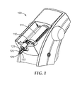
- Fig. 1 shows a device 100 for mixing and dispensing dental materials.
- the device 100 shown may for example be used to mix and dispense a hardenable dental impression material.
- a dental impression material may be used to fill a dental tray which is then placed into a patient's mouth to take a dental impression.
- the device 100 in the example shown is motorized and therefore allows for automatic mixing the dental material from two components and for automatic dispensation of the mixture.
- the device 100 holds the two components of the dental material in containers 110, 111 and is adapted to advance the components toward a mixer 120 in which the components can be mixed.
- the mixer 120 is removably attached to the device 100 such that it can be replaced by a fresh mixer after use.
- the mixer 120 has a mixing chamber formed between a rotatable mixing rotor 121 and a mixer housing 122 and is connectable with the containers 110, 111 such that the individual components can flow into the mixing chamber of the mixer 120.
- the mixture can exit through a mixer nozzle 123.
- the device 100 is adapted to drive the mixing rotor 121 so as to mix the components in the mixing chamber as they flow through the mixer 120.
- the device 100 thus implements a continuous dynamic mixing process in which components can be continuously supplied into the mixing chamber and in which the mixture from the components can be dispensed continuously from the mixer.
- the device 100 in the example has for each component a hydraulic actuator (not shown in this Figure) which allows the respective component to be advanced toward the mixer 120.
- Fig. 2 shows a first hydraulic actuator 10 and a second hydraulic actuator 20 which may be arranged within the device 100 shown in Fig. 1 .
- the containers 110, 111 are disposed relative to the actuators 10, 20 such that the actuators can advance the components (not shown) stored in the containers 110, 111 toward dispensing outlets 112, 113 of the respective containers 110, 111.
- the containers 110, 111 are cartridges having cartridge pistons 114, 115 respectively.
- Each container 110/111 thus may form a chamber for holding a component and the chamber may be closed by the cartridge piston 114/115 which is movably arranged within the chamber.
- the chamber opens into the dispensing outlet 112/113 so that the component can be extruded from the chamber by moving the cartridge piston 114/115 in the chamber toward the outlet 112/113.
- the components may be provided in foil bags and the foil bags may be received in the containers.
- Such a foil bag may be formed from a relatively thin and collabsible foil. The foil bag may be pierced open at one side and compressed to extrude the component from the foil bag.
- the dispensing outlet may form part of the foil bag rather than forming a part of the cartridge.
- the foil bag may be connected to a substantially rigid cap at which the dispensing outlet is formed.
- the foil bag may be pieced open by a needle or cutting blade inserted from outside through the dispensing outlet of the cap.
- the cap may comprise piercing members which automatically pierce the foil bag open as the foil bag is pressurized for extruding the component.
- a foil bag is described for example in US 6,012,610 . However the skilled person may recognize different container designs which may be likewise used with the present invention.
- the first and second hydraulic actuators 10, 20 in the example carry a first piston 19 and a second piston 29, respectively.
- the first and second pistons 19, 29 are dimensioned to fit within the chambers of the containers 110, 111, respectively, and the first and second hydraulic actuators 10, 20 are adapted to move the respective first and second pistons 19, 29 and thereby to advance the respective component toward the dispensing outlet.
- Fig. 3 only shows the first hydraulic actuator 10 for detailed explanation and therefore is generally referred to as "hydraulic actuator".
- the second hydraulic actuator 20 preferably comprises the same features as the hydraulic actuator 10. However, features of the first and second actuators 10, 20 may nevertheless differ in size even though such features may be technically identical otherwise.
- the hydraulic actuator 10 has a first thrust member 11 which is preferably arranged stationary in the mixing and dispensing device of the present invention. Thus the first thrust member 11 may be fixed at the mixing and dispensing device and may not move relative to the device when the hydraulic drive is operated.
- the hydraulic actuator 10 has a second thrust member 12 which is movably accommodated within the first thrust member 11, and further has a third thrust member 13 which is movably arranged within the second thrust member 12.
- the first thrust member 11 forms a first hollow cylinder 31, and the second thrust member forms a second hollow cylinder 32.
- the second thrust member 12 further forms a first plunger 33 for cooperation with the first cylinder 31 of the first thrust member.
- the third thrust member 13 forms a second plunger 34 for cooperation with the second cylinder 32 of the second thrust member.
- the hydraulic drive has two plungers which are movable into each other and these two plungers are further movable into a further cylinder.
- the first, second and third thrust members 11, 12, 13 are adapted to telescopically move relative to each other.
- the first and second plungers 32, 34 are sealingly and slidably arranged within the first and second cylinders 31, 32, respectively. Therefore the first, second and third thrust members 11, 12, 13 may be hydraulically movable relative to each other.
- the hydraulic actuator has a certain arrangement of seals for sealing the thrust members with one another.
- a first seal 14 is arranged at the first thrust member 11, and a second seal 15 is arranged at the third thrust member 13. Therefore the second thrust member 12 does not require any seal.
- the second thrust member 12 may be the only part of the hydraulic actuator 10 which requires precisely finished inner and outer surfaces for sliding on the first and second seals 14, 15.
- the second thrust member 12 may be the only part of the hydraulic actuator 10 which may need to be made resistant against wear from sliding with the seals. Therefore even though the hydraulic drive 10 has three thrust members it may be manufactured at efforts and costs that are similar to those related to the manufacturing of a hydraulic actuator having only two thrust members.
- two or more hydraulic actuators may have one common first thrust member.
- This common first thrust member may form at least two cylinders each movably accommodating a second thrust member, and that second thrust member further bears a third thrust member. This may help minimizing the amount of parts required for a hydraulic actuator, and therefore may help minimizing manufacturing costs.
- the first plunger 33 has a first plunger cross-section 35 in a plane perpendicular to the length of the hydraulic actuator 10
- the second plunger 34 has a second plunger cross-section 36 in a plane perpendicular to the length of the hydraulic actuator 10.
- the length of the hydraulic actuator for the purpose of this specification is a dimension in which the first, second and third thrust members are substantially linearly movable relative to each other for operation of the hydraulic actuator.
- the first and second cross-sections 35, 36 correspond to areas which are pressurized by the hydraulic fluid upon hydraulic operation of the hydraulic actuator 10. Due to the described seal arrangement the first and second cross-sections 35, 36 are similar so that the first and second plungers 33, 34 can be advanced at similar forces without changing the pressure of the hydraulic fluid.
- a hydraulic pump providing only for one constant pressure may be used. Therefore manufacturing costs may be further minimized.
- first and second cross-sections 35, 36 nevertheless are somewhat different, depending on a wall thickness of the second thrust member. It has however been found that such a difference in cross-section allows for extending the actuator at two slightly different forces and/or speeds.
- the hydraulic actuator may be controlled to extend by moving the first and second thrust members first without moving the third and second thrust members relative to each other. Thereby the actuator at a first partial movement extends at a first force. Subsequently the hydraulic actuator may be controlled to extend by moving the second and third thrust members without moving the first and second thrust members relative to each other.
- the actuator at a second partial movement extends at a second force which is slightly lower than the first force if the hydraulic pressure applied in the actuator is the same in the first and second partial movements. Thereby a difference in the required force for advancing a component in a container may be compensated.
- the hydraulic actuator may be first moved at a lower force and subsequently at a higher force.
- the hydraulic actuator may have a break for retaining at least two thrust members with one another.
- the first and second thrust members may be retained with each other while the second and third thrust members are enabled for movement with one another, or the second and third thrust members may be retained with each other while the second and first thrust member are enabled for movement with one another.
- the break may be a hydraulic or mechanical, or any other suitable brake.
- the Figure shows the hydraulic actuator 10 at a somewhat extended stage, meaning with the first, second and third thrust members 11, 12, 13 placed within each other with their ends only. Relative to the extended stage the hydraulic drive may further be brought toward a retracted stage by moving the first, second and third thrust members 11, 12, 13 into each other.
- the hydraulic actuator 10 is adapted to change in length.
- the hydraulic actuator 10 in a first operation mode can be operated through hydraulically activated movement of the thrust members relative to each other in a forward direction toward the extended stage.
- the hydraulic actuator 10 in an alternative second operation mode can be moved in an opposite backward direction toward the retracted stage.
- Retraction is preferably enabled non-hydraulically, for example manually or by spring load. This may help minimizing the complexity of the design of hydraulic actuator may help saving costs in the manufacturing and maintenance of the device.
- the thrust members are preferably dimensioned in length such that the hydraulic actuator is variable in length at a ratio between a fully retracted stage and a fully extended stage of less than 1/2, preferably of approximately 1/3.
- a device for mixing and dispensing may be relatively compact in size.
- Fig. 4 shows the first and second hydraulic actuators 10, 20 at a fully retracted stage.
- the fully retracted stage of the first and second hydraulic actuators 10, 20 allows the containers 110, 111 to be removed from the mixing and dispensing device (not shown in detail).
- the first and second hydraulic actuators 10, 20 at the fully retracted stage are shorter in length than the containers 110, 111 in the same dimension. Nevertheless (as apparent from Fig. 2 ) the first and second hydraulic actuators 10, 20 allow for substantially fully emptying of the containers because the first and second hydraulic actuators 10, 20 are preferably extendable by more than twice of their length of the retracted stage.
- Fig. 5 shows the first and second hydraulic actuators 10, 20 in a hydraulic system 200.
- the hydraulic system 200 has a reservoir 201 for holding a hydraulic fluid.
- the hydraulic system 200 further has a pump 202 for pressurizing the hydraulic fluid, and first and second supplies 203, 204 for connecting the first and second hydraulic actuators, respectively, to the pressure side of the pump 202.
- the pump 202 is arranged within a common supply 205. Further the first and second supplies 203, 204 and the common supply are connected with each other at the pressure side of the pump 202.
- the first and second supplies 203, 204 have a first and second control valve 206, 207, respectively.
- the control valves 206, 207 are preferably controlled such that the first and second actuators 10, 20 provide a predetermined flow ratio of the components relative to each other.
- the first and control valves 206, 207 may be controlled to allow similar flow rates of hydraulic fluid to flow in the first and second supplies 203, 204, respectively, and toward the first and second hydraulic actuators 10, 20, respectively.
- the first and second pistons 19, 29 may be advanced at similar speeds by the respective first and second hydraulic actuators 10, 20.
- the first and second control valves 206, 207 may be controlled electronically dependent on an actual movement provided by the first and second hydraulic actuators 10, 20, respectively.
- first and second hydraulic actuators 10, 20 may comprise a measuring system which provides information which are indicative of a current position of the pistons advanced by the hydraulic actuators to a controller, and the controller may control the first and second control valves 206, 207 to provide a predetermined relative positioning of the pistons to each other.
- the hydraulic system 200 further has a first and a second bypass 208, 209.
- the first bypass 208 connects the first supply 203 and the reservoir 201
- the second bypass connects the second supply 204 and the reservoir 201.
- Each of the first and second bypasses can be blocked or opened.
- hydraulic fluid pumped by the pump 202 may not cause the thrust members of the actuators to move, but may directly flow back toward the reservoir. This is because the movement of the thrust members may require a certain friction to be overcome which the relatively low pressure built up in the supply may not provide for.
- the thrust members may be enabled to be moved non-hydraulically.
- the actuator may be retracted manually or by spring force. Hydraulic fluid displaced from the actuators may also flow toward the reservoir 201 via the bypasses.
- the hydraulic fluid pumped by the pump 202 preferably causes the thrust members of the actuators to move.
- the hydraulic system 200 has a four-port / two-way valve 210 which allows for the first and second bypasses 208, 209 to be alternately blocked or opened.
- the four-port / two-way valve may normally provide for the open stage of the bypasses but may be activated for switching to the closed stage. Therefore the control of the hydraulic system may be minimized in complexity. For example it may not be necessary to switch the pump on and off for activating and deactivating the actuators.
- Fig. 6 shows a further hydraulic system 300 with the first and second hydraulic actuators 10, 20.
- the hydraulic system 300 has a reservoir 301 for holding a hydraulic fluid and first and second supplies 303, 304.
- the first supply 303 has a pump 302a
- the second supply 304 has a pump 302b.
- each of the first and second supplies 303, 304 has a pump 302a/302b for pressurizing the hydraulic fluid.
- the first and second supplies 303, 304 further connect the first and second hydraulic actuators 10, 20, respectively, to the pressure sides of the pumps 302a/302b.
- the first and second pumps 302a/302b are preferably controlled such that the first and second actuators 10, 20 provide a predetermined flow ratio of the components relative to each other.
- first and second pumps 302a/302b may be controlled to provide for similar flow rates of hydraulic fluid in the first and second supplies 303, 304, respectively, and toward the first and second hydraulic actuators 10, 20, respectively.
- first and second pistons 19, 29 may be advanced at similar speeds by the respective first and second hydraulic actuators 10, 20.
- the first and second pumps 302a/302b may be driven by a common motor 311 such that the first and pumps 302a/302b run at the same or similar speeds.
- first and second pumps 302a/302b may be driven at different speeds.
- the motor 311 drives the first pump 302a and a transmission between the motor 311 and the second pump 302b is provided.
- the transmission may comprise a gear box 312 which provides for the first and second pumps 302a/302b to run at different speeds.
- the gear box 312 may be adapted to run the first and second pumps 302a/302b at a predetermined speeds ratio.
- Such a speed ratio may for example correspond to the mixing ratio of the components to be mixed to form the dental material.
- an individually driven motor for each of the first and second pumps 302a/302b may be used, and such motors may be driven at a predetermined speed ratio.
- the actual positioning provided by the actuators may be captured as outlined in the example illustrated in Fig. 5 and used to control the motor speed or speeds.
- the hydraulic system 300 further has first and second bypasses 308, 309.
- the first bypass 308 connects the first supply 303 and the reservoir 301
- the second bypass 309 connects the second supply 304 and the reservoir 301.
- Each of the first and second bypasses can be blocked or opened as outlined in the example shown in Fig. 5 .
- the hydraulic system 300 again has a four-port / two-way valve 310 which enables the first and second bypasses 308, 309 to be alternately blocked or opened.
Landscapes
- Health & Medical Sciences (AREA)
- Oral & Maxillofacial Surgery (AREA)
- Dentistry (AREA)
- Epidemiology (AREA)
- Life Sciences & Earth Sciences (AREA)
- Animal Behavior & Ethology (AREA)
- General Health & Medical Sciences (AREA)
- Public Health (AREA)
- Veterinary Medicine (AREA)
- Accessories For Mixers (AREA)
Abstract
Description
- The invention relates to a device for mixing and dispensing a dental material, and in particular to a device which has at least two hydraulic actuators. The hydraulic actuators each comprise a plurality of thrust members which are movable relative to each other to provide for components of the dental material to be advanced toward a dispensing outlet. The invention further relates to a method of mixing and dispensing a dental material.
- In dentistry a variety of devices are available which allow for preparation and/or application of dental materials in a dentist's practice. In particular for preparation of materials that are typically used at larger amounts, like for example dental impression materials, devices have been developed that provide for automatic dispensing from packages and/or for mixing of such materials. An exemplary device for mixing and dispensing a dental impression material is for example available under the designation 3M™ ESPE™ Pentamix™ from 3M ESPE AG, Germany. Typically such a device allows for two material components to be simultaneously supplied from a package through a mixer where they are mixed. Often the devices provide for continuously extruding the components through a mixer, where the components are mixed as the components flow through the mixer and released from an outlet.
- The devices further typically have a motor driven piston for extruding the material from a container. A variety of different drive concepts have been proposed for driving the piston at a relatively high force as it may be required for appropriately dispensing the dental material.
- For example
EP 1 700 639 discloses a device for dispensing a flowable substance. The device comprises at least one force transmitting member (for example a push-pull chain) adapted to transmit a pushing force in a direction toward or opposite the substance and which can be gathered non-linearly. -
US 6,168,052 discloses an electrically driven dispensing appliance having an electric drive which acts via drive screws on thrust plates for dispensing material from cartridges. The drive screws are axially stationary and are in action relationship with a slide bearing said thrust plates. The electric drive comprises a first gear motor for a drive under high load during advance and relief, and a second motor for the drive under lower load during the retracting and fast advance motions. - Although there is a variety of devices on the market which provide for automatic mixing and dispensing there is still a desire to minimize costs for manufacturing of such devices and for providing the devices with maximized reliability.
- In a first aspect the invention relates to a device for mixing and dispensing a dental material from at least two components. The device comprises for each component a hydraulic actuator. The device is adapted such that the hydraulic actuator is operable to advance the respective component toward a dispensing outlet. Further each of the hydraulic actuators has at least three thrust members which are adapted to telescopically interact and move relative to each other.
- The device is advantageous because it may provide for a preparation of a dental material at a maximized mixing quality but may help minimizing costs for such preparation. Further the device of the invention may be relatively uncomplex in design, relatively robust, and relatively easy to use. The invention may further allow for a device which is minimized in size. Therefore the space required for the device in a dental practice may be minimized. Further the device may operate at a minimized noise level. Thus the acceptance in a dental practice may be maximized.
- In one embodiment the operation of the hydraulic actuator is provided through hydraulically activated movement of the thrust members relative to one another. A first of the three thrust members is preferably arranged stationary in the device and a second thrust member and a third thrust member are preferably arranged displaceable relative to the first thrust member. The second and third thrust members are preferably also movable relative to each other. The second thrust member is preferably arranged between the first and third thrust members. Thus the first, second and third thrust members may telescopically interact with one anther with the first thrust member movably accommodating the second thrust member, and the second thrust member movably accommodating the third thrust member.
- In a further embodiment the device comprises at least one further thrust member between the first and the third thrust members with the first thrust member and the further thrust member(s) being movable relative to each other, and the third thrust member and the further thrust member(s) being movable relative to each other. The device may further comprise a plurality of thrust members between the first and the third thrust members with each of the thrust members being movable relative to all other thrust members. Preferably the movement of the thrust members relative to each other is a linear or generally linear movement, in particular an exclusive linear movement.
- In one embodiment the third thrust member carries a piston to pressurize the respective component. Thus in operation of the hydraulic actuator the piston may be moved to advance the component toward the dispensing outlet by hydraulically activated movement of the thrust members.
- In one embodiment the hydraulic actuator in a first operation mode is operated through hydraulically activated movement of the thrust members relative to each other in a forward direction toward the dispensing outlet. Further in an alternative second operation mode the hydraulic actuator may be retractable in an opposite backward direction. The retraction of the hydraulic actuator in the second operation mode may be hydraulically activated, but is preferably manually activated, or activated by spring load. Thus the complexity of the design of the actuator may be minimized. Further a manual or spring activated retraction may provide for a backward movement at a higher speed than the hydraulically activated forward movement. This may be advantageous for quickly changing a component container because the hydraulic actuator may be quickly removed from the container and thus may quickly release the container for exchange.
- In a preferred embodiment the device has at least two actuators each having at least three thrust members. Such at least two hydraulic actuators may be connected to a common hydraulic system.
- For the purpose of this specification the term "connection" or "to connect" as it relates to the hydraulic system implies the establishment a fluid communication.
- The hydraulic system is preferably adapted to hydraulically activate each of the hydraulic actuators. The hydraulic system may have a reservoir for holding a hydraulic fluid. Further the hydraulic system for each hydraulic actuator may comprise a supply for supplying the hydraulic fluid to the hydraulic actuator. The hydraulic system further may have at least one pump for pressurizing the hydraulic fluid in the supply. Each supply between the pump and the hydraulic actuator are preferably additionally connectable for fluid communication with the reservoir via a bypass. Each bypass may comprise a valve for alternatively opening or blocking the connection with the reservoir. Such a hydraulic system preferably allows the hydraulic pump to continuously run and to establish a stable operation of the hydraulic system. In particular variations in pressure as they may occur due to typical start behaviour of a pump within a hydraulic system may be avoided. It has been found that particularly the initial phase of a mixing and dispensing process requires a precise control of the flow of the components into the mixer. To overcome poor mixing at such an initial phase mixers had been provided which have a special interior design, for example mixers that comprise a deflector or delay channel for one component to reproducibly cause a pre-flow of one component. The present invention is advantageous because it may provide for precisely controlled flow of the components into the mixer already during the initial phase of mixing and dispensing.
- In a further embodiment the hydraulic system has a common supply which diverts in the at least two supplies. The device may further have one pump within the common supply for pressurizing the hydraulic fluid in the at least two supplies. In this embodiment the hydraulic system may only have one pump. Further each of the supplies may have a control valve for individually controlling the flow of hydraulic fluid in the respective supplies. The control valve may in particular provide for controlling the flow of hydraulic fluid at a predetermined flow ratio.
- In still a further embodiment the device has a pump for each supply for pressurizing the hydraulic fluid in the respective supply. Thus the pumps may allow for individually control of the flow of hydraulic fluid in each supply. Therefore the at least two pumps may be driven to provide flow rates of the hydraulic fluid at a predetermined ratio relative to each other.
- The flow ratio - either controlled by the control valve or by the pumps ― may approximately correspond to a desired mixing ratio of the components to form the dental material. For example the device may have differently sized hydraulic actuators for providing different forces for advancing the components. The actuators may have different cross-sections in a plane perpendicular to the forward and backward direction which are effective for being pressurized by the hydraulic fluid. The areas of the cross-sections may for example in ratio correspond to the mixing ratio of the components. And accordingly the flow ratios of the hydraulic fluid toward the hydraulic actuators may also correspond to the mixing ratio of the components.
- In one embodiment the first thrust member forms a first hydraulic cylinder which movably accommodates the second thrust member, the second thrust member forms a first plunger in the first thrust member and further forms a second hydraulic cylinder which movably accommodates the third thrust member. Further in this embodiment the third thrust member forms a second plunger in the second thrust member. The inner diameter of the first cylinder is preferably greater than the outer diameter of the first plunger, and the gap between the first cylinder and the first plunger may be sealed by a first annular seal fixed at the first cylinder. Further the inner diameter of the second cylinder is preferably greater than the outer diameter of the second plunger, and the gap between the second cylinder and the second plunger may be sealed by a second annular seal fixed at the second plunger. Therefore the second thrust member may be free of any seal. Further the second thrust member may be the only thrust member requiring a finishing which is allows for sliding on the seals that are arranged at the other cooperating thrust members. Thus costs for manufacturing of the hydraulic actuator may be minimized.
- In one embodiment the device comprises at least two containers each containing a component. The components may be adapted to form a dental material, for example a dental impression material, when merged or mixed.
- In a further embodiment the device may comprise the mixer. The mixer may have at least two inlets each being connected or connectable with a container containing the component, and a mixer nozzle for releasing the mixture. The mixer may be a dynamic mixer comprising a mixing rotor which can be or is driven from outside the mixer, for example by a motor. Alternatively the mixer may be a static mixer which has one or more static mixing elements. The mixing rotor or the static mixing elements may agitate the components as they flow through the mixer and thus cause the components to merge and form the mixture.
- A further aspect of the invention relates to a method of mixing and dispensing a dental material. The method comprises the steps of:
- providing a device for mixing and dispensing a dental material from at least two components according to the invention, the device having at least two hydraulic actuators for advancing the components toward a mixer;
- providing at least two components that are to be mixed at a desired predetermined mixing ratio;
- controlling the hydraulic actuators such that the components flow toward the mixer at a first mixing ratio during a first mixing and dispensing phase; and
- controlling the hydraulic actuators to cause the components to flow toward the mixer at a second mixing ratio during a second mixing and dispensing phase; and
- wherein the first and second mixing and dispensing phases belong to one common mixing and dispensing phase to provide a quantity of a mixture; and
- wherein the first and second mixing ratios deviate or are different from the desired mixing ratio.
- In one embodiment the hydraulic actuators are controlled such that the average mixing ratio over the first, second phase and optionally a third phase are performed within one contiguous mixing and dispensing phase and such that the quantity achieved therefrom includes the components at the desired predetermined mixing ratio.
- Thus at the beginning of a mixing process a pre-flow of one component into the mixer may be caused by control of the hydraulic actuators. It has for example been found that a more homogeneous mixing may be achieved if a catalyser component reaches the mixer before a base component of a dental impression material. Once that pre-flow has been established in the first mixing and dispensing phases the flow ratio of the catalyser and base components may be changed in the second mixing and dispensing phase such that the overall quantity of the mixture comprises the components at the desired mixing ratio.
-
- Fig. 1
- is a perspective view of a mixing and dispensing device according to an embodiment of the invention;
- Fig. 2
- is a cross-sectional view of a part of the mixing and dispensing device according to an embodiment of the invention;
- Fig. 3
- is a cross-sectional view of a hydraulic actuator according to an embodiment of the invention;
- Fig. 4
- is a cross-sectional view of the part of the mixing and dispensing device shown in
Fig 2 , but at a different operation stage; - Fig. 5
- is a schematic plan illustrating a hydraulic system according to an embodiment of the invention; and
- Fig. 6
- is a schematic plan illustrating a hydraulic system according to another embodiment of the invention.
-
Fig. 1 shows adevice 100 for mixing and dispensing dental materials. Thedevice 100 shown may for example be used to mix and dispense a hardenable dental impression material. Such a dental impression material may be used to fill a dental tray which is then placed into a patient's mouth to take a dental impression. - The
device 100 in the example shown is motorized and therefore allows for automatic mixing the dental material from two components and for automatic dispensation of the mixture. Thedevice 100 holds the two components of the dental material incontainers mixer 120 in which the components can be mixed. Themixer 120 is removably attached to thedevice 100 such that it can be replaced by a fresh mixer after use. Themixer 120 has a mixing chamber formed between arotatable mixing rotor 121 and amixer housing 122 and is connectable with thecontainers mixer 120. The mixture can exit through amixer nozzle 123. Thedevice 100 is adapted to drive the mixingrotor 121 so as to mix the components in the mixing chamber as they flow through themixer 120. Thedevice 100 thus implements a continuous dynamic mixing process in which components can be continuously supplied into the mixing chamber and in which the mixture from the components can be dispensed continuously from the mixer. - The
device 100 in the example has for each component a hydraulic actuator (not shown in this Figure) which allows the respective component to be advanced toward themixer 120. -
Fig. 2 shows a firsthydraulic actuator 10 and a secondhydraulic actuator 20 which may be arranged within thedevice 100 shown inFig. 1 . Thecontainers actuators containers outlets respective containers - In the example shown the
containers cartridge pistons container 110/111 thus may form a chamber for holding a component and the chamber may be closed by thecartridge piston 114/115 which is movably arranged within the chamber. The chamber opens into the dispensingoutlet 112/113 so that the component can be extruded from the chamber by moving thecartridge piston 114/115 in the chamber toward theoutlet 112/113. In another example the components may be provided in foil bags and the foil bags may be received in the containers. Such a foil bag may be formed from a relatively thin and collabsible foil. The foil bag may be pierced open at one side and compressed to extrude the component from the foil bag. In one embodiment the dispensing outlet may form part of the foil bag rather than forming a part of the cartridge. In this case the foil bag may be connected to a substantially rigid cap at which the dispensing outlet is formed. The foil bag may be pieced open by a needle or cutting blade inserted from outside through the dispensing outlet of the cap. Alternatively the cap may comprise piercing members which automatically pierce the foil bag open as the foil bag is pressurized for extruding the component. Such a foil bag is described for example inUS 6,012,610 . However the skilled person may recognize different container designs which may be likewise used with the present invention. - The first and second
hydraulic actuators first piston 19 and asecond piston 29, respectively. The first andsecond pistons containers hydraulic actuators second pistons -
Fig. 3 only shows the firsthydraulic actuator 10 for detailed explanation and therefore is generally referred to as "hydraulic actuator". The secondhydraulic actuator 20 preferably comprises the same features as thehydraulic actuator 10. However, features of the first andsecond actuators - The
hydraulic actuator 10 has afirst thrust member 11 which is preferably arranged stationary in the mixing and dispensing device of the present invention. Thus thefirst thrust member 11 may be fixed at the mixing and dispensing device and may not move relative to the device when the hydraulic drive is operated. Thehydraulic actuator 10 has asecond thrust member 12 which is movably accommodated within thefirst thrust member 11, and further has athird thrust member 13 which is movably arranged within thesecond thrust member 12. Thefirst thrust member 11 forms a firsthollow cylinder 31, and the second thrust member forms a secondhollow cylinder 32. Thesecond thrust member 12 further forms afirst plunger 33 for cooperation with thefirst cylinder 31 of the first thrust member. Further thethird thrust member 13 forms asecond plunger 34 for cooperation with thesecond cylinder 32 of the second thrust member. Therefore the hydraulic drive has two plungers which are movable into each other and these two plungers are further movable into a further cylinder. Thus the first, second andthird thrust members second plungers second cylinders third thrust members - The hydraulic actuator has a certain arrangement of seals for sealing the thrust members with one another. A
first seal 14 is arranged at thefirst thrust member 11, and asecond seal 15 is arranged at thethird thrust member 13. Therefore thesecond thrust member 12 does not require any seal. Further thesecond thrust member 12 may be the only part of thehydraulic actuator 10 which requires precisely finished inner and outer surfaces for sliding on the first andsecond seals second thrust member 12 may be the only part of thehydraulic actuator 10 which may need to be made resistant against wear from sliding with the seals. Therefore even though thehydraulic drive 10 has three thrust members it may be manufactured at efforts and costs that are similar to those related to the manufacturing of a hydraulic actuator having only two thrust members. - In one embodiment (not shown) two or more hydraulic actuators may have one common first thrust member. This common first thrust member may form at least two cylinders each movably accommodating a second thrust member, and that second thrust member further bears a third thrust member. This may help minimizing the amount of parts required for a hydraulic actuator, and therefore may help minimizing manufacturing costs.
- The
first plunger 33 has afirst plunger cross-section 35 in a plane perpendicular to the length of thehydraulic actuator 10, and thesecond plunger 34 has asecond plunger cross-section 36 in a plane perpendicular to the length of thehydraulic actuator 10. The length of the hydraulic actuator for the purpose of this specification is a dimension in which the first, second and third thrust members are substantially linearly movable relative to each other for operation of the hydraulic actuator. The first andsecond cross-sections hydraulic actuator 10. Due to the described seal arrangement the first andsecond cross-sections second plungers - The skilled person will recognize that the first and
second cross-sections - The Figure shows the
hydraulic actuator 10 at a somewhat extended stage, meaning with the first, second andthird thrust members third thrust members hydraulic actuator 10 is adapted to change in length. Preferably thehydraulic actuator 10 in a first operation mode can be operated through hydraulically activated movement of the thrust members relative to each other in a forward direction toward the extended stage. Further thehydraulic actuator 10 in an alternative second operation mode can be moved in an opposite backward direction toward the retracted stage. Retraction is preferably enabled non-hydraulically, for example manually or by spring load. This may help minimizing the complexity of the design of hydraulic actuator may help saving costs in the manufacturing and maintenance of the device. - The thrust members are preferably dimensioned in length such that the hydraulic actuator is variable in length at a ratio between a fully retracted stage and a fully extended stage of less than 1/2, preferably of approximately 1/3. Thus a device for mixing and dispensing may be relatively compact in size.
-
Fig. 4 shows the first and secondhydraulic actuators hydraulic actuators containers hydraulic actuators containers Fig. 2 ) the first and secondhydraulic actuators hydraulic actuators -
Fig. 5 shows the first and secondhydraulic actuators hydraulic system 200. Thehydraulic system 200 has areservoir 201 for holding a hydraulic fluid. Thehydraulic system 200 further has apump 202 for pressurizing the hydraulic fluid, and first andsecond supplies pump 202. Thepump 202 is arranged within acommon supply 205. Further the first andsecond supplies pump 202. The first andsecond supplies second control valve control valves second actuators hydraulic actuators control valves second supplies hydraulic actuators second pistons hydraulic actuators second control valves hydraulic actuators hydraulic actuators second control valves - The
hydraulic system 200 further has a first and asecond bypass 208, 209. Thefirst bypass 208 connects thefirst supply 203 and thereservoir 201, whereas the second bypass connects thesecond supply 204 and thereservoir 201. Each of the first and second bypasses can be blocked or opened. In the opened stage of the bypasses hydraulic fluid in the respective supplies can flow back toward thereservoir 201. Therefore hydraulic fluid pumped by thepump 202 may not cause the thrust members of the actuators to move, but may directly flow back toward the reservoir. This is because the movement of the thrust members may require a certain friction to be overcome which the relatively low pressure built up in the supply may not provide for. Further in the open stage of the bypasses the thrust members may be enabled to be moved non-hydraulically. In particular the actuator may be retracted manually or by spring force. Hydraulic fluid displaced from the actuators may also flow toward thereservoir 201 via the bypasses. - In the closed stage of the bypasses the hydraulic fluid pumped by the
pump 202 preferably causes the thrust members of the actuators to move. - The
hydraulic system 200 has a four-port / two-way valve 210 which allows for the first andsecond bypasses 208, 209 to be alternately blocked or opened. The four-port / two-way valve may normally provide for the open stage of the bypasses but may be activated for switching to the closed stage. Therefore the control of the hydraulic system may be minimized in complexity. For example it may not be necessary to switch the pump on and off for activating and deactivating the actuators. -
Fig. 6 shows a furtherhydraulic system 300 with the first and secondhydraulic actuators hydraulic system 300 has areservoir 301 for holding a hydraulic fluid and first andsecond supplies first supply 303 has apump 302a, and thesecond supply 304 has apump 302b. Thus each of the first andsecond supplies pump 302a/302b for pressurizing the hydraulic fluid. The first andsecond supplies hydraulic actuators pumps 302a/302b. The first andsecond pumps 302a/302b are preferably controlled such that the first andsecond actuators hydraulic actuators second pumps 302a/302b may be controlled to provide for similar flow rates of hydraulic fluid in the first andsecond supplies hydraulic actuators second pistons hydraulic actuators second pumps 302a/302b may be driven by acommon motor 311 such that the first andpumps 302a/302b run at the same or similar speeds. However for example in case differently dimensioned hydraulic actuators are used the first andsecond pumps 302a/302b may be driven at different speeds. In the example themotor 311 drives thefirst pump 302a and a transmission between themotor 311 and thesecond pump 302b is provided. The transmission may comprise agear box 312 which provides for the first andsecond pumps 302a/302b to run at different speeds. Thegear box 312 may be adapted to run the first andsecond pumps 302a/302b at a predetermined speeds ratio. Such a speed ratio may for example correspond to the mixing ratio of the components to be mixed to form the dental material. Further an individually driven motor for each of the first andsecond pumps 302a/302b may be used, and such motors may be driven at a predetermined speed ratio. - The actual positioning provided by the actuators may be captured as outlined in the example illustrated in
Fig. 5 and used to control the motor speed or speeds. - The
hydraulic system 300 further has first andsecond bypasses 308, 309. Thefirst bypass 308 connects thefirst supply 303 and thereservoir 301, and the second bypass 309 connects thesecond supply 304 and thereservoir 301. Each of the first and second bypasses can be blocked or opened as outlined in the example shown inFig. 5 . Thehydraulic system 300 again has a four-port / two-way valve 310 which enables the first andsecond bypasses 308, 309 to be alternately blocked or opened.
Claims (15)
- A device for mixing and dispensing a dental material from at least two components, comprising for each component a hydraulic actuator, wherein the device is adapted such that the hydraulic actuator is operable to advance the respective component toward a dispensing outlet, wherein the hydraulic actuator having at least three thrust members which for operation of the hydraulic actuator are adapted to telescopically move relative to each other.
- The device of claim 1, wherein a first of the three thrust members is arranged stationary in the device and a second thrust member and a third thrust member are arranged displaceable relative to the first thrust member.
- The device of claim 2, wherein the second and third thrust members are movable relative to each other, and wherein the second thrust member is arranged between the first and third thrust members.
- The device of claim 2 or 3, comprising at least one further thrust member between the first and third thrust members with the first thrust member and the further thrust member(s) being movable relative to each other, and the third thrust member and the further thrust member(s) being movable relative to each other.
- The device of any of the claims 2 to 4, wherein the third thrust member carries a piston to pressurize the respective component.
- The device of any of the preceding claims, wherein the hydraulic actuator in a first operation mode is operated through hydraulically activated movement of the thrust members relative to each other in a forward direction toward the dispensing outlet, and in an alternative second operation mode the hydraulic actuator is retractable in an opposite backward direction.
- The device of claim 6, wherein retraction of the hydraulic actuator in the second operation mode is hydraulically activated, manually activated, or activated by spring load.
- The device of any of the preceding claims, wherein the at least two hydraulic actuators are connected to a common hydraulic system, wherein the hydraulic system is adapted to hydraulically activate each of the hydraulic actuators.
- The device of claim 8, wherein the hydraulic system has a reservoir for holding a hydraulic fluid, for each hydraulic actuator a supply for supplying the hydraulic fluid to one hydraulic actuator, and at least one pump for pressurizing the hydraulic fluid in the supply, each supply between the pump and the hydraulic actuator being additionally connectable for fluid communication with the reservoir via a bypass, and wherein the bypass comprises a valve for alternatively opening or blocking the connection with the reservoir.
- The device of claim 9, in which the hydraulic system has a common supply which diverts in the at least two supplies, the device further having one pump within the common supply for pressurizing the hydraulic fluid in the at least two supplies.
- The device of claim 10, in which the device has a pump for each supply for pressurizing the hydraulic fluid in the respective supply.
- The device of claim 11, in which the at least two pumps are driven to provide flow rates of the hydraulic fluid at a predetermined ratio relative to each other.
- The device of claim 12, wherein the flow rate ratio approximately corresponds to a desired mixing ratio of the components to form the dental material.
- The device of any of the claims 2 to 13, in which:- the first thrust member forms a first hydraulic cylinder which movably accommodates the second thrust member,- the second thrust member forming a first plunger in the first thrust member and forming a second hydraulic cylinder which movably accommodates the third thrust member,- the third thrust member forming a second plunger in the second thrust member,- wherein the inner diameter of the first cylinder is greater than the outer diameter of the first plunger, and the gap between the first cylinder and the first plunger is sealed by a first annular seal fixed at the first cylinder, and- wherein the inner diameter of the second cylinder is greater than the outer diameter of the second plunger, and the gap between the second cylinder and the second plunger is sealed by a second annular seal fixed at the second plunger.
- A method of mixing and dispensing a dental material, comprising the steps of:- providing a device for mixing and dispensing a dental material from at least two components, the device having at least two hydraulic actuators for advancing the components toward a mixer;- providing at least two components that are to be mixed at a desired predetermined mixing ratio;- controlling the hydraulic actuators such that the components flow toward the mixer at a first mixing ratio during a first mixing and dispensing phase; and- controlling the hydraulic actuators to cause the components to flow toward the mixer at a second mixing ratio during a second mixing and dispensing phase; and- wherein the first and second mixing and dispensing phases belong to one common mixing and dispensing phase to provide a quantity of a mixture; and- wherein the first and second mixing ratios deviate from the desired mixing ratio.
Priority Applications (1)
| Application Number | Priority Date | Filing Date | Title |
|---|---|---|---|
| EP20110157737 EP2497442B1 (en) | 2011-03-10 | 2011-03-10 | A device for mixing and dispensing a dental material |
Applications Claiming Priority (1)
| Application Number | Priority Date | Filing Date | Title |
|---|---|---|---|
| EP20110157737 EP2497442B1 (en) | 2011-03-10 | 2011-03-10 | A device for mixing and dispensing a dental material |
Publications (2)
| Publication Number | Publication Date |
|---|---|
| EP2497442A1 true EP2497442A1 (en) | 2012-09-12 |
| EP2497442B1 EP2497442B1 (en) | 2014-11-19 |
Family
ID=44262475
Family Applications (1)
| Application Number | Title | Priority Date | Filing Date |
|---|---|---|---|
| EP20110157737 Not-in-force EP2497442B1 (en) | 2011-03-10 | 2011-03-10 | A device for mixing and dispensing a dental material |
Country Status (1)
| Country | Link |
|---|---|
| EP (1) | EP2497442B1 (en) |
Citations (6)
| Publication number | Priority date | Publication date | Assignee | Title |
|---|---|---|---|---|
| DE3607176A1 (en) * | 1986-03-05 | 1987-09-10 | Hilti Ag | Metering unit for plastic compositions |
| EP0525562A1 (en) * | 1991-07-29 | 1993-02-03 | OFFICINE MECCANICHE A.N.I. S.p.A. | Device for dispensing fluid and/or semi-fluid products |
| US6012610A (en) | 1996-02-05 | 2000-01-11 | Thera Patent Gmbh & Co. Kg Gesellschaft Fur Industrielle Schutzrechte | Device for emptying a film tube |
| US6168052B1 (en) | 1998-05-15 | 2001-01-02 | Wilhelm A. Keller | Electrically operated cartridge dispensing appliance |
| US6921002B2 (en) * | 2003-03-21 | 2005-07-26 | Kettenbach Gmbh & Co. Kg | Device for dispensing one- and multi-component compounds and valve arrangement for this purpose |
| EP1700639A1 (en) | 2005-03-11 | 2006-09-13 | 3M Innovative Properties Company | Dispensing device |
-
2011
- 2011-03-10 EP EP20110157737 patent/EP2497442B1/en not_active Not-in-force
Patent Citations (6)
| Publication number | Priority date | Publication date | Assignee | Title |
|---|---|---|---|---|
| DE3607176A1 (en) * | 1986-03-05 | 1987-09-10 | Hilti Ag | Metering unit for plastic compositions |
| EP0525562A1 (en) * | 1991-07-29 | 1993-02-03 | OFFICINE MECCANICHE A.N.I. S.p.A. | Device for dispensing fluid and/or semi-fluid products |
| US6012610A (en) | 1996-02-05 | 2000-01-11 | Thera Patent Gmbh & Co. Kg Gesellschaft Fur Industrielle Schutzrechte | Device for emptying a film tube |
| US6168052B1 (en) | 1998-05-15 | 2001-01-02 | Wilhelm A. Keller | Electrically operated cartridge dispensing appliance |
| US6921002B2 (en) * | 2003-03-21 | 2005-07-26 | Kettenbach Gmbh & Co. Kg | Device for dispensing one- and multi-component compounds and valve arrangement for this purpose |
| EP1700639A1 (en) | 2005-03-11 | 2006-09-13 | 3M Innovative Properties Company | Dispensing device |
Also Published As
| Publication number | Publication date |
|---|---|
| EP2497442B1 (en) | 2014-11-19 |
Similar Documents
| Publication | Publication Date | Title |
|---|---|---|
| EP2593241B1 (en) | A device for dispensing a dental material | |
| US8684229B2 (en) | Dispenser and method for dispensing dental material | |
| US8424718B2 (en) | Method of mixing and extruding viscous materials and gearbox for dispensing the same | |
| EP1087842B1 (en) | Electronic fluid dispenser | |
| US8807394B2 (en) | System comprising a mixing and dispensing device and a material container | |
| US8613376B2 (en) | Device for dispensing a dental material | |
| EP2736443B1 (en) | Cartridge for dispensing a dental substance | |
| EP2497442B1 (en) | A device for mixing and dispensing a dental material | |
| EP3265016B1 (en) | Dental material delivery system | |
| US6921002B2 (en) | Device for dispensing one- and multi-component compounds and valve arrangement for this purpose |
Legal Events
| Date | Code | Title | Description |
|---|---|---|---|
| PUAI | Public reference made under article 153(3) epc to a published international application that has entered the european phase |
Free format text: ORIGINAL CODE: 0009012 |
|
| AK | Designated contracting states |
Kind code of ref document: A1 Designated state(s): AL AT BE BG CH CY CZ DE DK EE ES FI FR GB GR HR HU IE IS IT LI LT LU LV MC MK MT NL NO PL PT RO RS SE SI SK SM TR |
|
| AX | Request for extension of the european patent |
Extension state: BA ME |
|
| 17P | Request for examination filed |
Effective date: 20130227 |
|
| GRAP | Despatch of communication of intention to grant a patent |
Free format text: ORIGINAL CODE: EPIDOSNIGR1 |
|
| RIC1 | Information provided on ipc code assigned before grant |
Ipc: B05C 17/015 20060101ALN20140702BHEP Ipc: A61C 9/00 20060101AFI20140702BHEP |
|
| RIC1 | Information provided on ipc code assigned before grant |
Ipc: B05C 17/015 20060101ALN20140715BHEP Ipc: A61C 9/00 20060101AFI20140715BHEP |
|
| INTG | Intention to grant announced |
Effective date: 20140728 |
|
| GRAS | Grant fee paid |
Free format text: ORIGINAL CODE: EPIDOSNIGR3 |
|
| GRAA | (expected) grant |
Free format text: ORIGINAL CODE: 0009210 |
|
| AK | Designated contracting states |
Kind code of ref document: B1 Designated state(s): AL AT BE BG CH CY CZ DE DK EE ES FI FR GB GR HR HU IE IS IT LI LT LU LV MC MK MT NL NO PL PT RO RS SE SI SK SM TR |
|
| REG | Reference to a national code |
Ref country code: GB Ref legal event code: FG4D |
|
| REG | Reference to a national code |
Ref country code: CH Ref legal event code: EP |
|
| REG | Reference to a national code |
Ref country code: AT Ref legal event code: REF Ref document number: 696543 Country of ref document: AT Kind code of ref document: T Effective date: 20141215 |
|
| REG | Reference to a national code |
Ref country code: IE Ref legal event code: FG4D |
|
| REG | Reference to a national code |
Ref country code: DE Ref legal event code: R096 Ref document number: 602011011430 Country of ref document: DE Effective date: 20141231 |
|
| REG | Reference to a national code |
Ref country code: NL Ref legal event code: VDEP Effective date: 20141119 |
|
| REG | Reference to a national code |
Ref country code: AT Ref legal event code: MK05 Ref document number: 696543 Country of ref document: AT Kind code of ref document: T Effective date: 20141119 |
|
| REG | Reference to a national code |
Ref country code: LT Ref legal event code: MG4D |
|
| PG25 | Lapsed in a contracting state [announced via postgrant information from national office to epo] |
Ref country code: NO Free format text: LAPSE BECAUSE OF FAILURE TO SUBMIT A TRANSLATION OF THE DESCRIPTION OR TO PAY THE FEE WITHIN THE PRESCRIBED TIME-LIMIT Effective date: 20150219 Ref country code: PT Free format text: LAPSE BECAUSE OF FAILURE TO SUBMIT A TRANSLATION OF THE DESCRIPTION OR TO PAY THE FEE WITHIN THE PRESCRIBED TIME-LIMIT Effective date: 20150319 Ref country code: IS Free format text: LAPSE BECAUSE OF FAILURE TO SUBMIT A TRANSLATION OF THE DESCRIPTION OR TO PAY THE FEE WITHIN THE PRESCRIBED TIME-LIMIT Effective date: 20150319 Ref country code: FI Free format text: LAPSE BECAUSE OF FAILURE TO SUBMIT A TRANSLATION OF THE DESCRIPTION OR TO PAY THE FEE WITHIN THE PRESCRIBED TIME-LIMIT Effective date: 20141119 Ref country code: ES Free format text: LAPSE BECAUSE OF FAILURE TO SUBMIT A TRANSLATION OF THE DESCRIPTION OR TO PAY THE FEE WITHIN THE PRESCRIBED TIME-LIMIT Effective date: 20141119 Ref country code: NL Free format text: LAPSE BECAUSE OF FAILURE TO SUBMIT A TRANSLATION OF THE DESCRIPTION OR TO PAY THE FEE WITHIN THE PRESCRIBED TIME-LIMIT Effective date: 20141119 Ref country code: LT Free format text: LAPSE BECAUSE OF FAILURE TO SUBMIT A TRANSLATION OF THE DESCRIPTION OR TO PAY THE FEE WITHIN THE PRESCRIBED TIME-LIMIT Effective date: 20141119 |
|
| PG25 | Lapsed in a contracting state [announced via postgrant information from national office to epo] |
Ref country code: RS Free format text: LAPSE BECAUSE OF FAILURE TO SUBMIT A TRANSLATION OF THE DESCRIPTION OR TO PAY THE FEE WITHIN THE PRESCRIBED TIME-LIMIT Effective date: 20141119 Ref country code: AT Free format text: LAPSE BECAUSE OF FAILURE TO SUBMIT A TRANSLATION OF THE DESCRIPTION OR TO PAY THE FEE WITHIN THE PRESCRIBED TIME-LIMIT Effective date: 20141119 Ref country code: LV Free format text: LAPSE BECAUSE OF FAILURE TO SUBMIT A TRANSLATION OF THE DESCRIPTION OR TO PAY THE FEE WITHIN THE PRESCRIBED TIME-LIMIT Effective date: 20141119 Ref country code: SE Free format text: LAPSE BECAUSE OF FAILURE TO SUBMIT A TRANSLATION OF THE DESCRIPTION OR TO PAY THE FEE WITHIN THE PRESCRIBED TIME-LIMIT Effective date: 20141119 Ref country code: HR Free format text: LAPSE BECAUSE OF FAILURE TO SUBMIT A TRANSLATION OF THE DESCRIPTION OR TO PAY THE FEE WITHIN THE PRESCRIBED TIME-LIMIT Effective date: 20141119 Ref country code: GR Free format text: LAPSE BECAUSE OF FAILURE TO SUBMIT A TRANSLATION OF THE DESCRIPTION OR TO PAY THE FEE WITHIN THE PRESCRIBED TIME-LIMIT Effective date: 20150220 Ref country code: CY Free format text: LAPSE BECAUSE OF FAILURE TO SUBMIT A TRANSLATION OF THE DESCRIPTION OR TO PAY THE FEE WITHIN THE PRESCRIBED TIME-LIMIT Effective date: 20141119 Ref country code: PL Free format text: LAPSE BECAUSE OF FAILURE TO SUBMIT A TRANSLATION OF THE DESCRIPTION OR TO PAY THE FEE WITHIN THE PRESCRIBED TIME-LIMIT Effective date: 20141119 |
|
| PG25 | Lapsed in a contracting state [announced via postgrant information from national office to epo] |
Ref country code: EE Free format text: LAPSE BECAUSE OF FAILURE TO SUBMIT A TRANSLATION OF THE DESCRIPTION OR TO PAY THE FEE WITHIN THE PRESCRIBED TIME-LIMIT Effective date: 20141119 Ref country code: SK Free format text: LAPSE BECAUSE OF FAILURE TO SUBMIT A TRANSLATION OF THE DESCRIPTION OR TO PAY THE FEE WITHIN THE PRESCRIBED TIME-LIMIT Effective date: 20141119 Ref country code: CZ Free format text: LAPSE BECAUSE OF FAILURE TO SUBMIT A TRANSLATION OF THE DESCRIPTION OR TO PAY THE FEE WITHIN THE PRESCRIBED TIME-LIMIT Effective date: 20141119 Ref country code: RO Free format text: LAPSE BECAUSE OF FAILURE TO SUBMIT A TRANSLATION OF THE DESCRIPTION OR TO PAY THE FEE WITHIN THE PRESCRIBED TIME-LIMIT Effective date: 20141119 Ref country code: DK Free format text: LAPSE BECAUSE OF FAILURE TO SUBMIT A TRANSLATION OF THE DESCRIPTION OR TO PAY THE FEE WITHIN THE PRESCRIBED TIME-LIMIT Effective date: 20141119 |
|
| REG | Reference to a national code |
Ref country code: DE Ref legal event code: R097 Ref document number: 602011011430 Country of ref document: DE |
|
| PLBE | No opposition filed within time limit |
Free format text: ORIGINAL CODE: 0009261 |
|
| STAA | Information on the status of an ep patent application or granted ep patent |
Free format text: STATUS: NO OPPOSITION FILED WITHIN TIME LIMIT |
|
| 26N | No opposition filed |
Effective date: 20150820 |
|
| PG25 | Lapsed in a contracting state [announced via postgrant information from national office to epo] |
Ref country code: LU Free format text: LAPSE BECAUSE OF FAILURE TO SUBMIT A TRANSLATION OF THE DESCRIPTION OR TO PAY THE FEE WITHIN THE PRESCRIBED TIME-LIMIT Effective date: 20150310 Ref country code: MC Free format text: LAPSE BECAUSE OF FAILURE TO SUBMIT A TRANSLATION OF THE DESCRIPTION OR TO PAY THE FEE WITHIN THE PRESCRIBED TIME-LIMIT Effective date: 20141119 |
|
| GBPC | Gb: european patent ceased through non-payment of renewal fee |
Effective date: 20150310 |
|
| PG25 | Lapsed in a contracting state [announced via postgrant information from national office to epo] |
Ref country code: IT Free format text: LAPSE BECAUSE OF FAILURE TO SUBMIT A TRANSLATION OF THE DESCRIPTION OR TO PAY THE FEE WITHIN THE PRESCRIBED TIME-LIMIT Effective date: 20141119 |
|
| REG | Reference to a national code |
Ref country code: FR Ref legal event code: ST Effective date: 20151130 |
|
| REG | Reference to a national code |
Ref country code: IE Ref legal event code: MM4A |
|
| PG25 | Lapsed in a contracting state [announced via postgrant information from national office to epo] |
Ref country code: IE Free format text: LAPSE BECAUSE OF NON-PAYMENT OF DUE FEES Effective date: 20150310 Ref country code: GB Free format text: LAPSE BECAUSE OF NON-PAYMENT OF DUE FEES Effective date: 20150310 |
|
| PG25 | Lapsed in a contracting state [announced via postgrant information from national office to epo] |
Ref country code: SI Free format text: LAPSE BECAUSE OF FAILURE TO SUBMIT A TRANSLATION OF THE DESCRIPTION OR TO PAY THE FEE WITHIN THE PRESCRIBED TIME-LIMIT Effective date: 20141119 Ref country code: FR Free format text: LAPSE BECAUSE OF NON-PAYMENT OF DUE FEES Effective date: 20150331 |
|
| PG25 | Lapsed in a contracting state [announced via postgrant information from national office to epo] |
Ref country code: MT Free format text: LAPSE BECAUSE OF FAILURE TO SUBMIT A TRANSLATION OF THE DESCRIPTION OR TO PAY THE FEE WITHIN THE PRESCRIBED TIME-LIMIT Effective date: 20141119 |
|
| PGFP | Annual fee paid to national office [announced via postgrant information from national office to epo] |
Ref country code: CH Payment date: 20170314 Year of fee payment: 7 Ref country code: DE Payment date: 20170307 Year of fee payment: 7 |
|
| PG25 | Lapsed in a contracting state [announced via postgrant information from national office to epo] |
Ref country code: SM Free format text: LAPSE BECAUSE OF FAILURE TO SUBMIT A TRANSLATION OF THE DESCRIPTION OR TO PAY THE FEE WITHIN THE PRESCRIBED TIME-LIMIT Effective date: 20141119 Ref country code: BG Free format text: LAPSE BECAUSE OF FAILURE TO SUBMIT A TRANSLATION OF THE DESCRIPTION OR TO PAY THE FEE WITHIN THE PRESCRIBED TIME-LIMIT Effective date: 20141119 Ref country code: HU Free format text: LAPSE BECAUSE OF FAILURE TO SUBMIT A TRANSLATION OF THE DESCRIPTION OR TO PAY THE FEE WITHIN THE PRESCRIBED TIME-LIMIT; INVALID AB INITIO Effective date: 20110310 |
|
| PG25 | Lapsed in a contracting state [announced via postgrant information from national office to epo] |
Ref country code: TR Free format text: LAPSE BECAUSE OF FAILURE TO SUBMIT A TRANSLATION OF THE DESCRIPTION OR TO PAY THE FEE WITHIN THE PRESCRIBED TIME-LIMIT Effective date: 20141119 |
|
| PG25 | Lapsed in a contracting state [announced via postgrant information from national office to epo] |
Ref country code: BE Free format text: LAPSE BECAUSE OF FAILURE TO SUBMIT A TRANSLATION OF THE DESCRIPTION OR TO PAY THE FEE WITHIN THE PRESCRIBED TIME-LIMIT Effective date: 20141119 |
|
| PG25 | Lapsed in a contracting state [announced via postgrant information from national office to epo] |
Ref country code: MK Free format text: LAPSE BECAUSE OF FAILURE TO SUBMIT A TRANSLATION OF THE DESCRIPTION OR TO PAY THE FEE WITHIN THE PRESCRIBED TIME-LIMIT Effective date: 20141119 |
|
| REG | Reference to a national code |
Ref country code: DE Ref legal event code: R119 Ref document number: 602011011430 Country of ref document: DE |
|
| PG25 | Lapsed in a contracting state [announced via postgrant information from national office to epo] |
Ref country code: AL Free format text: LAPSE BECAUSE OF FAILURE TO SUBMIT A TRANSLATION OF THE DESCRIPTION OR TO PAY THE FEE WITHIN THE PRESCRIBED TIME-LIMIT Effective date: 20141119 |
|
| REG | Reference to a national code |
Ref country code: CH Ref legal event code: PL |
|
| PG25 | Lapsed in a contracting state [announced via postgrant information from national office to epo] |
Ref country code: DE Free format text: LAPSE BECAUSE OF NON-PAYMENT OF DUE FEES Effective date: 20181002 |
|
| PG25 | Lapsed in a contracting state [announced via postgrant information from national office to epo] |
Ref country code: CH Free format text: LAPSE BECAUSE OF NON-PAYMENT OF DUE FEES Effective date: 20180331 Ref country code: LI Free format text: LAPSE BECAUSE OF NON-PAYMENT OF DUE FEES Effective date: 20180331 |