EP2496181B1 - Bioprothèse aortique et systèmes de mise en place de celle-ci - Google Patents
Bioprothèse aortique et systèmes de mise en place de celle-ci Download PDFInfo
- Publication number
- EP2496181B1 EP2496181B1 EP10751680.9A EP10751680A EP2496181B1 EP 2496181 B1 EP2496181 B1 EP 2496181B1 EP 10751680 A EP10751680 A EP 10751680A EP 2496181 B1 EP2496181 B1 EP 2496181B1
- Authority
- EP
- European Patent Office
- Prior art keywords
- stent
- valve
- degree
- crown
- section
- Prior art date
- Legal status (The legal status is an assumption and is not a legal conclusion. Google has not performed a legal analysis and makes no representation as to the accuracy of the status listed.)
- Active
Links
- 238000004873 anchoring Methods 0.000 claims description 201
- 230000006641 stabilisation Effects 0.000 claims description 83
- 238000011105 stabilization Methods 0.000 claims description 80
- 210000000709 aorta Anatomy 0.000 claims description 37
- 238000004891 communication Methods 0.000 claims description 22
- 230000004323 axial length Effects 0.000 claims description 21
- 230000002093 peripheral effect Effects 0.000 claims 5
- 210000002216 heart Anatomy 0.000 description 43
- 238000000034 method Methods 0.000 description 41
- 210000003709 heart valve Anatomy 0.000 description 35
- 210000005240 left ventricle Anatomy 0.000 description 34
- 238000002513 implantation Methods 0.000 description 23
- 210000001765 aortic valve Anatomy 0.000 description 19
- 210000004351 coronary vessel Anatomy 0.000 description 16
- 239000003550 marker Substances 0.000 description 16
- 239000000463 material Substances 0.000 description 16
- 210000001519 tissue Anatomy 0.000 description 14
- 230000005012 migration Effects 0.000 description 13
- 238000013508 migration Methods 0.000 description 13
- 238000013459 approach Methods 0.000 description 12
- 229920000728 polyester Polymers 0.000 description 12
- 239000007943 implant Substances 0.000 description 10
- 241000124008 Mammalia Species 0.000 description 9
- 230000000747 cardiac effect Effects 0.000 description 8
- 210000004115 mitral valve Anatomy 0.000 description 8
- 239000008280 blood Substances 0.000 description 7
- 210000004369 blood Anatomy 0.000 description 7
- 238000002788 crimping Methods 0.000 description 7
- 210000003516 pericardium Anatomy 0.000 description 7
- 230000006378 damage Effects 0.000 description 6
- 238000013461 design Methods 0.000 description 6
- 230000036961 partial effect Effects 0.000 description 6
- 230000002829 reductive effect Effects 0.000 description 6
- 208000027418 Wounds and injury Diseases 0.000 description 5
- 239000004744 fabric Substances 0.000 description 5
- 208000014674 injury Diseases 0.000 description 5
- HLXZNVUGXRDIFK-UHFFFAOYSA-N nickel titanium Chemical compound [Ti].[Ti].[Ti].[Ti].[Ti].[Ti].[Ti].[Ti].[Ti].[Ti].[Ti].[Ni].[Ni].[Ni].[Ni].[Ni].[Ni].[Ni].[Ni].[Ni].[Ni].[Ni].[Ni].[Ni].[Ni] HLXZNVUGXRDIFK-UHFFFAOYSA-N 0.000 description 5
- 229910001000 nickel titanium Inorganic materials 0.000 description 5
- 230000007704 transition Effects 0.000 description 5
- 210000000591 tricuspid valve Anatomy 0.000 description 5
- 210000002376 aorta thoracic Anatomy 0.000 description 4
- 230000035487 diastolic blood pressure Effects 0.000 description 4
- 238000011010 flushing procedure Methods 0.000 description 4
- 239000002184 metal Substances 0.000 description 4
- 229910052751 metal Inorganic materials 0.000 description 4
- 210000003102 pulmonary valve Anatomy 0.000 description 4
- 239000010935 stainless steel Substances 0.000 description 4
- 229910001220 stainless steel Inorganic materials 0.000 description 4
- 230000002861 ventricular Effects 0.000 description 4
- 241000283690 Bos taurus Species 0.000 description 3
- 208000004434 Calcinosis Diseases 0.000 description 3
- 206010067171 Regurgitation Diseases 0.000 description 3
- FAPWRFPIFSIZLT-UHFFFAOYSA-M Sodium chloride Chemical compound [Na+].[Cl-] FAPWRFPIFSIZLT-UHFFFAOYSA-M 0.000 description 3
- 238000005452 bending Methods 0.000 description 3
- 230000008901 benefit Effects 0.000 description 3
- 230000017531 blood circulation Effects 0.000 description 3
- 230000002308 calcification Effects 0.000 description 3
- 230000006870 function Effects 0.000 description 3
- 230000009191 jumping Effects 0.000 description 3
- 210000004072 lung Anatomy 0.000 description 3
- 238000012986 modification Methods 0.000 description 3
- 230000004048 modification Effects 0.000 description 3
- 230000008569 process Effects 0.000 description 3
- IJGRMHOSHXDMSA-UHFFFAOYSA-N Atomic nitrogen Chemical compound N#N IJGRMHOSHXDMSA-UHFFFAOYSA-N 0.000 description 2
- 208000001778 Coronary Occlusion Diseases 0.000 description 2
- 206010011086 Coronary artery occlusion Diseases 0.000 description 2
- SXRSQZLOMIGNAQ-UHFFFAOYSA-N Glutaraldehyde Chemical compound O=CCCCC=O SXRSQZLOMIGNAQ-UHFFFAOYSA-N 0.000 description 2
- 241001465754 Metazoa Species 0.000 description 2
- 208000031481 Pathologic Constriction Diseases 0.000 description 2
- 230000001580 bacterial effect Effects 0.000 description 2
- 238000010009 beating Methods 0.000 description 2
- 210000004204 blood vessel Anatomy 0.000 description 2
- 230000008859 change Effects 0.000 description 2
- 238000005520 cutting process Methods 0.000 description 2
- 230000003247 decreasing effect Effects 0.000 description 2
- 238000009826 distribution Methods 0.000 description 2
- 230000000694 effects Effects 0.000 description 2
- 230000023597 hemostasis Effects 0.000 description 2
- 238000001727 in vivo Methods 0.000 description 2
- 238000003780 insertion Methods 0.000 description 2
- 230000037431 insertion Effects 0.000 description 2
- 230000003993 interaction Effects 0.000 description 2
- 238000003698 laser cutting Methods 0.000 description 2
- 238000013146 percutaneous coronary intervention Methods 0.000 description 2
- 238000002360 preparation method Methods 0.000 description 2
- 210000001147 pulmonary artery Anatomy 0.000 description 2
- 230000009467 reduction Effects 0.000 description 2
- 230000004044 response Effects 0.000 description 2
- 210000005241 right ventricle Anatomy 0.000 description 2
- 238000009958 sewing Methods 0.000 description 2
- 239000011780 sodium chloride Substances 0.000 description 2
- 230000036262 stenosis Effects 0.000 description 2
- 208000037804 stenosis Diseases 0.000 description 2
- 238000001356 surgical procedure Methods 0.000 description 2
- 201000001320 Atherosclerosis Diseases 0.000 description 1
- 241000894006 Bacteria Species 0.000 description 1
- 208000035143 Bacterial infection Diseases 0.000 description 1
- 206010017533 Fungal infection Diseases 0.000 description 1
- 241001272720 Medialuna californiensis Species 0.000 description 1
- 208000031888 Mycoses Diseases 0.000 description 1
- 208000012868 Overgrowth Diseases 0.000 description 1
- 206010036595 Premature delivery Diseases 0.000 description 1
- 208000012287 Prolapse Diseases 0.000 description 1
- 206010040748 Sinus perforation Diseases 0.000 description 1
- 241000282887 Suidae Species 0.000 description 1
- 201000001943 Tricuspid Valve Insufficiency Diseases 0.000 description 1
- 206010044642 Tricuspid valve stenosis Diseases 0.000 description 1
- 230000002411 adverse Effects 0.000 description 1
- 229910045601 alloy Inorganic materials 0.000 description 1
- 239000000956 alloy Substances 0.000 description 1
- 230000004075 alteration Effects 0.000 description 1
- 210000003484 anatomy Anatomy 0.000 description 1
- 238000002399 angioplasty Methods 0.000 description 1
- 210000001367 artery Anatomy 0.000 description 1
- 239000012237 artificial material Substances 0.000 description 1
- 208000022362 bacterial infectious disease Diseases 0.000 description 1
- 230000009286 beneficial effect Effects 0.000 description 1
- 239000000560 biocompatible material Substances 0.000 description 1
- 230000000903 blocking effect Effects 0.000 description 1
- 230000002612 cardiopulmonary effect Effects 0.000 description 1
- 210000000038 chest Anatomy 0.000 description 1
- 238000007887 coronary angioplasty Methods 0.000 description 1
- 208000029078 coronary artery disease Diseases 0.000 description 1
- 230000006735 deficit Effects 0.000 description 1
- 210000001105 femoral artery Anatomy 0.000 description 1
- 238000002594 fluoroscopy Methods 0.000 description 1
- 239000011888 foil Substances 0.000 description 1
- 230000002538 fungal effect Effects 0.000 description 1
- 238000010438 heat treatment Methods 0.000 description 1
- 230000000004 hemodynamic effect Effects 0.000 description 1
- 230000003601 intercostal effect Effects 0.000 description 1
- 210000005246 left atrium Anatomy 0.000 description 1
- 230000000670 limiting effect Effects 0.000 description 1
- 239000007788 liquid Substances 0.000 description 1
- 201000003453 lung abscess Diseases 0.000 description 1
- 238000004519 manufacturing process Methods 0.000 description 1
- 230000013011 mating Effects 0.000 description 1
- 230000007246 mechanism Effects 0.000 description 1
- 239000007769 metal material Substances 0.000 description 1
- 150000002739 metals Chemical class 0.000 description 1
- 210000004165 myocardium Anatomy 0.000 description 1
- 229910052757 nitrogen Inorganic materials 0.000 description 1
- 230000001453 nonthrombogenic effect Effects 0.000 description 1
- 230000010412 perfusion Effects 0.000 description 1
- 238000007888 peripheral angioplasty Methods 0.000 description 1
- 239000004033 plastic Substances 0.000 description 1
- 229920003023 plastic Polymers 0.000 description 1
- -1 polytetrafluoroethylene Polymers 0.000 description 1
- 229920001343 polytetrafluoroethylene Polymers 0.000 description 1
- 239000004810 polytetrafluoroethylene Substances 0.000 description 1
- 229920002635 polyurethane Polymers 0.000 description 1
- 239000004814 polyurethane Substances 0.000 description 1
- 230000002028 premature Effects 0.000 description 1
- 230000004224 protection Effects 0.000 description 1
- 230000002685 pulmonary effect Effects 0.000 description 1
- 230000001172 regenerating effect Effects 0.000 description 1
- 230000002787 reinforcement Effects 0.000 description 1
- 238000009256 replacement therapy Methods 0.000 description 1
- 210000005245 right atrium Anatomy 0.000 description 1
- 238000000926 separation method Methods 0.000 description 1
- 238000004904 shortening Methods 0.000 description 1
- 210000003291 sinus of valsalva Anatomy 0.000 description 1
- 230000002966 stenotic effect Effects 0.000 description 1
- 210000001562 sternum Anatomy 0.000 description 1
- 238000006467 substitution reaction Methods 0.000 description 1
- 230000009885 systemic effect Effects 0.000 description 1
- 238000002560 therapeutic procedure Methods 0.000 description 1
- 210000000115 thoracic cavity Anatomy 0.000 description 1
- 238000011282 treatment Methods 0.000 description 1
- 238000011144 upstream manufacturing Methods 0.000 description 1
Images


Classifications
-
- A—HUMAN NECESSITIES
- A61—MEDICAL OR VETERINARY SCIENCE; HYGIENE
- A61F—FILTERS IMPLANTABLE INTO BLOOD VESSELS; PROSTHESES; DEVICES PROVIDING PATENCY TO, OR PREVENTING COLLAPSING OF, TUBULAR STRUCTURES OF THE BODY, e.g. STENTS; ORTHOPAEDIC, NURSING OR CONTRACEPTIVE DEVICES; FOMENTATION; TREATMENT OR PROTECTION OF EYES OR EARS; BANDAGES, DRESSINGS OR ABSORBENT PADS; FIRST-AID KITS
- A61F2/00—Filters implantable into blood vessels; Prostheses, i.e. artificial substitutes or replacements for parts of the body; Appliances for connecting them with the body; Devices providing patency to, or preventing collapsing of, tubular structures of the body, e.g. stents
- A61F2/02—Prostheses implantable into the body
- A61F2/24—Heart valves ; Vascular valves, e.g. venous valves; Heart implants, e.g. passive devices for improving the function of the native valve or the heart muscle; Transmyocardial revascularisation [TMR] devices; Valves implantable in the body
- A61F2/2412—Heart valves ; Vascular valves, e.g. venous valves; Heart implants, e.g. passive devices for improving the function of the native valve or the heart muscle; Transmyocardial revascularisation [TMR] devices; Valves implantable in the body with soft flexible valve members, e.g. tissue valves shaped like natural valves
- A61F2/2418—Scaffolds therefor, e.g. support stents
-
- A—HUMAN NECESSITIES
- A61—MEDICAL OR VETERINARY SCIENCE; HYGIENE
- A61F—FILTERS IMPLANTABLE INTO BLOOD VESSELS; PROSTHESES; DEVICES PROVIDING PATENCY TO, OR PREVENTING COLLAPSING OF, TUBULAR STRUCTURES OF THE BODY, e.g. STENTS; ORTHOPAEDIC, NURSING OR CONTRACEPTIVE DEVICES; FOMENTATION; TREATMENT OR PROTECTION OF EYES OR EARS; BANDAGES, DRESSINGS OR ABSORBENT PADS; FIRST-AID KITS
- A61F2/00—Filters implantable into blood vessels; Prostheses, i.e. artificial substitutes or replacements for parts of the body; Appliances for connecting them with the body; Devices providing patency to, or preventing collapsing of, tubular structures of the body, e.g. stents
- A61F2/02—Prostheses implantable into the body
- A61F2/24—Heart valves ; Vascular valves, e.g. venous valves; Heart implants, e.g. passive devices for improving the function of the native valve or the heart muscle; Transmyocardial revascularisation [TMR] devices; Valves implantable in the body
- A61F2/2412—Heart valves ; Vascular valves, e.g. venous valves; Heart implants, e.g. passive devices for improving the function of the native valve or the heart muscle; Transmyocardial revascularisation [TMR] devices; Valves implantable in the body with soft flexible valve members, e.g. tissue valves shaped like natural valves
-
- A—HUMAN NECESSITIES
- A61—MEDICAL OR VETERINARY SCIENCE; HYGIENE
- A61F—FILTERS IMPLANTABLE INTO BLOOD VESSELS; PROSTHESES; DEVICES PROVIDING PATENCY TO, OR PREVENTING COLLAPSING OF, TUBULAR STRUCTURES OF THE BODY, e.g. STENTS; ORTHOPAEDIC, NURSING OR CONTRACEPTIVE DEVICES; FOMENTATION; TREATMENT OR PROTECTION OF EYES OR EARS; BANDAGES, DRESSINGS OR ABSORBENT PADS; FIRST-AID KITS
- A61F2/00—Filters implantable into blood vessels; Prostheses, i.e. artificial substitutes or replacements for parts of the body; Appliances for connecting them with the body; Devices providing patency to, or preventing collapsing of, tubular structures of the body, e.g. stents
- A61F2/02—Prostheses implantable into the body
- A61F2/24—Heart valves ; Vascular valves, e.g. venous valves; Heart implants, e.g. passive devices for improving the function of the native valve or the heart muscle; Transmyocardial revascularisation [TMR] devices; Valves implantable in the body
- A61F2/2427—Devices for manipulating or deploying heart valves during implantation
- A61F2/2436—Deployment by retracting a sheath
-
- A—HUMAN NECESSITIES
- A61—MEDICAL OR VETERINARY SCIENCE; HYGIENE
- A61F—FILTERS IMPLANTABLE INTO BLOOD VESSELS; PROSTHESES; DEVICES PROVIDING PATENCY TO, OR PREVENTING COLLAPSING OF, TUBULAR STRUCTURES OF THE BODY, e.g. STENTS; ORTHOPAEDIC, NURSING OR CONTRACEPTIVE DEVICES; FOMENTATION; TREATMENT OR PROTECTION OF EYES OR EARS; BANDAGES, DRESSINGS OR ABSORBENT PADS; FIRST-AID KITS
- A61F2220/00—Fixations or connections for prostheses classified in groups A61F2/00 - A61F2/26 or A61F2/82 or A61F9/00 or A61F11/00 or subgroups thereof
- A61F2220/0025—Connections or couplings between prosthetic parts, e.g. between modular parts; Connecting elements
- A61F2220/0058—Connections or couplings between prosthetic parts, e.g. between modular parts; Connecting elements soldered or brazed or welded
-
- A—HUMAN NECESSITIES
- A61—MEDICAL OR VETERINARY SCIENCE; HYGIENE
- A61F—FILTERS IMPLANTABLE INTO BLOOD VESSELS; PROSTHESES; DEVICES PROVIDING PATENCY TO, OR PREVENTING COLLAPSING OF, TUBULAR STRUCTURES OF THE BODY, e.g. STENTS; ORTHOPAEDIC, NURSING OR CONTRACEPTIVE DEVICES; FOMENTATION; TREATMENT OR PROTECTION OF EYES OR EARS; BANDAGES, DRESSINGS OR ABSORBENT PADS; FIRST-AID KITS
- A61F2230/00—Geometry of prostheses classified in groups A61F2/00 - A61F2/26 or A61F2/82 or A61F9/00 or A61F11/00 or subgroups thereof
- A61F2230/0002—Two-dimensional shapes, e.g. cross-sections
- A61F2230/0028—Shapes in the form of latin or greek characters
- A61F2230/0054—V-shaped
Definitions
- Embodiments of the present disclosure are directed to devices for cardiac valve replacement in mammalian hearts.
- PHVT percutaneous heart valve replacement therapies
- WO2009/053497 discloses stents and valved-stents, wherein the stent component comprises a first stent section, a second stent section , a third stent section and a fourth stent section.
- the first stent section may define an at least partly conical body and the first end of the stent component.
- the conical body of the first stent section may slope outwardly in the direction of the first end.
- the first stent section may include at least one attachment element for removable attachment to a delivery device.
- the second stent section may be in communication with the first stent section and may define an at least partly conical body.
- the conical body of the second stent section may slope outwardly in the direction of the second end.
- the third stent section may be in communication with the second stent section and may define an at least partially cylindrical body.
- the third stent section may be configured to house at least a portion of the valve component.
- the third stent section may include a plurality of arches for fixation to a corresponding plurality of commissures of the valve component.
- the fourth stent section may be in communication with the third stent section and may define the second end.
- the fourth stent section may further define an at least partly conical body, which may slope outwardly in the direction of the second end.
- the fourth stent section may include a plurality of arches larger than, but aligned with, the plurality of arches included in the third stent section.
- US2007/213813 also discloses stent-valves including a valve component and at least one stent component.
- the stent component may include a first section (e.g., proximal section), a second section configured to house the valve component, and a third section (e.g., distal section).
- the stent and valve components may be capable of at least two configurations: a collapsed configuration (e.g., during delivery) and an expanded configuration (e.g., after implantation).
- the first section of the stent valve may include a fixation element.
- a fixation element may include, for example, an annular groove for securing the stent-valve in place at an implantation site.
- the third section of the stent component may include at least one attachment element.
- a replacement valve for use within a human body
- the replacement valve includes a valve component and a stent component
- the replacement valve also being referred to as a valved-stent or a stent(-)valve, and may be used interchangeably with replacement valve throughout the disclosure.
- the stent component defines a first (e.g., proximal) end and a second (e.g., distal) end and may include a plurality of stent sections.
- the proximal end P of the stent component may be described as the end of the stent component/replacement valve which ultimately is positioned adjacent and/or within the left ventricle.
- the proximal end P of the stent component may comprise one or more anchoring or attachment elements for attachment to the delivery catheter ( e.g ., attachment end in a transapical delivery system).
- the distal end D of the stent component may be described as the end of the replacement valve/stent component which ultimately is positioned adjacent and/or near the ascending aorta, when, for example, the delivery catheter is advanced toward/into the ascending aorta in a transapical delivery system.
- the replacement valves are released distal-to-proximal, that is, the end of the stent (replacement valve) which ultimately is positioned within/near/adjacent the aorta is released before the end of the stent (replacement valve) which ultimately is positioned within/near/adjacent the ventricle is released last.
- a delivery is via a transapical approach, or through the heart muscle (as opposed to being delivered transvascularly).
- a replacement valve for use within a human body comprising: a valve component; and a stent component configured to house at least a portion of the valve component comprising a proximal end and a distal end, the stent component further comprising: a lower anchoring crown comprising an at least partly conical body, where the lower anchoring crown defines the proximal end of the stent component; an upper anchoring crown in communication with the lower anchoring crown and comprising an at least partly conical body, where the conical body of the lower anchoring crown slopes outwardly in the direction of the proximal end, and the conical body of the upper anchoring crown slopes outwardly in the direction of the distal end; the distal stent section comprising an at least partly conical body, where the distal stent section is in communication with the upper anchoring crown, preferably the distal stent section comprises a conical or cylindrical commissural post section and a stabilization arch section, where the commissural post section
- the term "partly conical body” shall mean that the crown may have any divergent shape.
- the upper and/or the lower anchoring crown may include a plurality of subsequent conical sections with different inclinations or may have a continuously increasing or decreasing divergence, e.g. may have a trumpet.-mouth like shape.
- the upper and/or the lower anchoring crown may also include one or more cylindrical sections or inwardly converging sections.
- the upper and lower anchoring crown may meet at a line where the stent has a minimal diameter.
- the commissural post section meets the lower and/or upper anchoring crown at the same line, where the upper anchoring crown meets the lower anchoring crown.
- the conical body of the lower anchoring crown may slope outwardly from an inner diameter D2 to an outer diameter D3 in the direction of the proximal end, where the inner diameter D2 is between about 20 mm to about 30 mm, and the outer diameter D3 is between about 22 mm to about 40 mm.
- the axial distance between the planes of the diameters D2 and D3 in the expanded configuration may be between about 3 to about 15 mm.
- the outward slope of the lower anchoring crown may be defined by an angle ⁇ 2, where ⁇ 2 is between from about 5 degree to about 50 degree.
- the conical body of the upper anchoring crown slopes outwardly from an inner diameter D2 to an outer diameter D1 in the direction of the distal end, where the inner diameter D2 may be between about 20 mm to about 30 mm, and the outer diameter D1 is between about 22 mm to about 40 mm.
- the axial distance between the planes of the diameters D2 and D1 in the expanded configuration may be between about 3 to about 10 mm.
- the outward slope of the upper anchoring crown may be defined by an angle ⁇ 1, where ⁇ 1 is between from about 10 degree to about 80 degree.
- the end of the upper anchoring crown forms a tip, where the tip is bent inwardly toward the longitudinal axis at an angle ⁇ 3 as compared to the direction of the crown surface, and ⁇ 3 is between from about 0 degree to about 180 degree.
- the length of the combined upper anchoring crown and commissural post section of the stent component H3 may be between about 3 to about 50 mm.
- the length of the stabilization arches and of the stent component H4 may be between about 5 to about 50 mm.
- the upper and/or lower crown may include a cylindrical or only slightly outwardly sloping section, thus there is a substantially cylindrical section between the actually diverging part of the upper conical crown and the actually diverging part of the lower conical crown.
- the substantially cylindrical section sometimes is referred to as the trunk section.
- the axial length of the trunk section may be greater than 3 mm. Additionally or alternatively, the length of the trunk section may be less than 7 mm. For example, the axial length of the trunk section may be between 4 and 6 mm.
- the axial length of the substantially cylindrical section is at least 50% of the axial length of at least one of the lower or upper anchoring crown and/or wherein the axial length of the substantially cylindrical section is equal to or greater than the axial length of at least one of the first and second sections.
- substantially cylindrical or only slightly outwardly sloping sections are sections having an inclination angle of less than 10 degree with respect to the axis of the stent.
- the lower anchoring crown is configured to create a form fit with an inflow of an aortic valve and thus prevent migration of the stent component and the valve component towards the ascending aorta.
- the upper anchoring crown is configured to create a form fit with an outflow tract and native leaflets of an aortic valve and thus prevent migration of the stent component and the valve component towards the left ventricle.
- the tips of the upper anchoring crown may rest in a final position on or against the pushed back native valve leaflets and thus prevent migration of the stent component and the valve component towards the ascending aorta and/or towards the left ventricle.
- the commissural post section comprises a plurality of commissural posts configured for fixation to commissures of the valve component.
- the distal stent section comprises a plurality of stabilization arches for bearing against the ascending aorta for alignment of the stent-component with respect to the ascending aorta, each stabilization arch comprises a divergent portion that diverges away from the stent axis, in a direction towards the distal end; and an arch apex inclined at an angle ( ⁇ 5) measured from the divergent portion in a direction towards the stent axis.
- the stabilization arches or loops are configured to engage the ascending aorta to orient the stent component, the valve component, and an associated delivery system longitudinally within an aorta/aortic annulus thus preventing tilting of the stent component and the valve component during the implantation procedure and/or when implanted.
- At least one limb (or strut) of at least one arch comprises an asymmetric feature.
- the limb comprises a pattern, for example one or more kinks, such that the limb is different from another limb of the arch and may be distinguished from the other limb in a projected image.
- the asymmetric feature may provide information about the rotational alignment during implantation for example when observed on an X-ray projection.
- the lower anchoring crown comprises at least one attachment element for removable attachment to a delivery device.
- the (or at least one) attachment element is formed generally in the form of an opening which is able to enlarge when the stent component radially expands.
- the opening is adapted to receive a pin arranged on the stent holder.
- the attachment element may be formed by an axial elongation of at least one cell of the lower crown.
- three attachment elements are formed by three such elongated cells, optionally equally spaced around the perimeter.
- the or each elongated element is adapted to receive a respective pin projecting radially on the stent holder.
- the attachment element may be formed generally in the shape of a hook.
- the attachment element is formed by an elongation of at least one cell of the lower crown which is inwardly inclined and/or bent.
- Preferably three attachment elements are formed by three such elongated cells, optionally equally spaced around the perimeter of the stent and bent inwardly.
- the or each inclined attachment element may be adapted to be received by a groove arranged on a stent holder and/or to engage a respective pin extending or projecting axially on the stent holder.
- the stent component comprises a plurality of commissural posts for fixation to a corresponding plurality of valve commissures.
- a stent component may be provided that includes a central, longitudinal axis and at least one attachment element for removable attachment to a delivery device.
- the at least one attachment element may be formed generally in the shape of a hook extending inwardly towards the central, longitudinal axis.
- the delivery device may include a stent holder comprising a groove for receiving the attachment element of the stent component, where release of the stent-valve from the stent holder may be facilitated by rotation of the stent holder relative to the attachment element.
- a replacement valve for use within a human body includes a valve component, a stent component for housing the valve component, and at least two skirts (e.g ., polyester (PET) skirts).
- An inner skirt may be provided that covers at least a portion (e.g., all) of an outer surface of the valve component, where the inner skirt may be sutured to at least the inflow tract of the valve component and to an inner surface of the stent.
- An outer skirt may also be provided that is sutured onto an outer surface of the stent.
- a cardiac stent-valve delivery system may include an inner assembly and an outer assembly.
- the inner assembly may include a guide wire lumen (e.g ., polymeric tubing) and a stent holder for removable attachment to a stent-valve.
- the outer assembly may include a sheath.
- the inner member and the outer member may be co-axially positioned and slidable relative to one another in order to transition from a closed position to an open position, such that in the closed position the sheath encompasses the stent-valve still attached to the stent holder and thus constrains expansion of the stent-valve. In the open position, the outer sheath may not constrain expansion of the stent-valve and thus the stent-valve may detach from the stent holder and expand to a fully expanded configuration.
- the inner assembly of the delivery device may include a radioopaque marker band or fluoroscopic marker fixed to the guide wire lumen distal of the stent holder.
- the diameter of the outer assembly of the delivery device may vary over its longitudinal axis.
- An aortic valve may be replaced within a human body.
- a stent-valve may be covered with a sheath in order to maintain the stent-valve in a collapsed configuration.
- the stent-valve may then may be inserted in the collapsed configuration into the human body without contacting the ascending aorta or aortic arch.
- the stent-valve may be partially expanded by sliding the sheath towards the left ventricle of the heart. This sliding of the sheath towards the left ventricle may cause expansion of a distal end of the stent-valve while the proximal end of the stent-valve remains constrained by the sheath.
- the sheath may be further slid towards the left ventricle of the heart in order to cause full expansion of the stent-valve.
- the stent-valve may be recaptured prior to its full expansion by sliding the sheath in the opposite direction.
- a method for cardiac valve replacement may include releasing a distal end of a stent-valve from a sheath, where the distal end includes a radiopaque marker positioned thereon (e.g ., radioopaque marker band).
- the stent-valve is rotated, if necessary, to orient the stent-valve appropriately with respect to the coronary arteries ( e.g ., to prevent the commissures from facing the coronary arteries).
- the stabilization arches or loops of the stent-valve are released from the sheath, in order to cause at least one of the stabilization arches to contact the aorta.
- the upper anchoring crown of the stent-valve is released from the sheath and is brought into contact with the native valve leaflets.
- a lower anchoring crown of the stent-valve is released from the sheath and brought into contact with an annulus/inflow tract.
- the lower anchoring crown may be the proximal section of the stent-valve such that releasing the lower anchoring crown causes the stent-valve to be fully released from the sheath of the delivery device.
- a system for replacing a valve within a human body may comprise: a delivery device; and a replacement valve for use within a human body comprising: a valve component, and a stent component configured to house at least a portion of the valve component comprising a proximal end and a distal end, the stent component further comprising: a lower anchoring crown defining an at least partly conical body, where the lower anchoring crown defines the proximal end of the stent component; an upper anchoring crown in communication with the lower anchoring crown and defining an at least partly conical body, where the conical body of the lower anchoring crown slopes outwardly in the direction of the proximal end, and the conical body of the upper anchoring crown slopes outwardly in the direction of the distal end; the distal stent section defines an at least partly conical body, where the distal stent section comprises a conical commissural post section and stabilization arch section, where the commissural post section is in communication with the upper anchoring crown; and
- the stabilization arch may slope outwardly from the commissural post and/or turn inwardly at its apex remote from the commissural post.
- the stent component may have a central, longitudinal axis and comprising at least one attachment element for removable attachment to a delivery device, where the at least one attachment element is located at a proximal end of the stent component, where the proximal end is defined as the end toward the left ventricle when delivered from a transapical approach.
- the (at least one) attachment element may be formed generally in the form of an opening which is able to enlarge when the stent component radially expands.
- the opening is adapted to receive a pin arranged on the stent holder.
- the attachment element may be formed by an axial elongation of at least one cell of the lower crown.
- three attachment elements are formed by three such elongated cells, optionally equally spaced around the perimeter.
- the or each elongated element is adapted to receive a respective pin arranged, preferably radially, on the stent holder.
- the (at least one) attachment element may beformed generally in the shape of a hook.
- the attachment element is formed by an elongation of at least one cell of the lower crown which is inwardly inclined and/or bent.
- Preferably three attachment elements are formed by three such elongated cells, optionally equally spaced around the perimeter of the stent and bent inwardly.
- the or each inclined attachment element may be adapted to be received by a groove arranged on a stent holder and/or to engage a respective pin arranged on the stent holder.
- the delivery device may comprise: an inner member comprising a guide wire lumen and a stent holder; and an outer member comprising a sheath; where the stent holder comprises for example a groove for receiving the attachment element of the stent component and/or at least one pin for engaging an attachment element of the stent element in form of an opening,
- the pins may be arranged radially to engage axial elongations of the stent element or the pins may subtend an angle smaller than 90 degree with the axis of the stent holder, preferably may be arranged axially, to engage an inwardly inclined or bent attachment element with an opening.
- the axial pins may be arranged in a circumferential groove of the stent holder.
- Each radial pin may be arranged in a separate axial groove of the stent holder. Preferably there are three grooves equally spaced around the perimeter of the stent holder to receive corresponding attachment elements of the stent.
- the stent holder may comprise ramp surfaces to facilitate the release of the stent component after removing the sheath from the stent.
- each of the axial grooves comprises ramp surfaces, for example facets on either sides of the groove, to facilitate the lifting of the attachment elements when the stent expands.
- ramp surfaces for example facets on either sides of the groove
- the inner member and the outer member are co-axially positioned and slidable relative to one another in order to transition from a closed position to an open position, such that in the closed position the sheath encompasses at least a portion of the stent-valve still attached to the stent holder constraining expansion of the stent-valve, and such that in the open position the outer sheath does not constrain expansion of the stent-valve and the stent-valve detaches from the stent holder and expands to an expanded configuration.
- the release of the stent-valve from the stent holder may optionally be facilitated by slight rotation and/or axial movement of the stent holder relative to the attachment element.
- An aortic valve may be replaced within a human body, the method comprising: covering the replacement valves of the present invention with a sheath in order to maintain the replacement valve in a collapsed configuration; transapically inserting the replacement valve still in the collapsed configuration into the human body; partially expanding the replacement valve by sliding the sheath towards the left ventricle of the heart, wherein said sliding of the sheath towards the left ventricle causes expansion of a distal end of the replacement valve while the proximal end of the replacement valve remains constrained by the sheath; and further sliding the sheath towards the left ventricle of the heart in order to substantially release the entire replacement valve such that the replacement valve is allowed to expand to an expanded configuration.
- the method may comprise sliding the sheath in the opposite direction prior to said full expansion in order to recapture the replacement valve within the sheath.
- a cardiac valve may be replaced comprising: releasing a distal end of the replacement valves of the present invention from a sheath, wherein the distal end comprises a radiopaque marker; rotating the replacement valve, if necessary, to orient the replacement valve appropriately with respect to the coronary arteries; releasing arches of the replacement valve from the sheath, in order to cause at least one of the arches to contact the aorta; releasing a first conical crown of the replacement valve from the sheath, in order to cause the first conical crown to contact native valve leaflets; and releasing a second crown of the replacement valve from the sheath, in order to cause the second crown to contact an annulus/inflow tract, wherein the second crown comprises the proximal section of the replacement valve and said releasing of the second crown comprises fully releasing the replacement valve from the sheath.
- a cardiac valve may be replaced comprising: releasing a distal end of the replacement valves of the present invention from a sheath, wherein the distal end comprises a radiopaque marker and a plurality of arches; rotating the replacement valve, if necessary, to orient the replacement valve appropriately with respect to the coronary arteries; releasing the arches of the replacement valve from the sheath, in order to urge the arches towards (and optionally contacting) an area above a native valve; releasing a first conical crown portion of the replacement valve from the sheath, in order to cause the first conical crown to contact the native valve leaflets; and releasing a second crown portion of the replacement valve from the sheath, in order to cause the second crown to contact an annulus/inflow tract of the native valve, wherein the second crown is the proximal section of the replacement valve and said releasing the second crown comprises fully releasing the replacement valve from the sheath.
- a worn or diseased valve may be replaced comprising: transapically implanting the replacement valves of the present invention, wherein the replacement valve comprises: a valve component; and a stent component to which the valve component is affixed thereto, the stent component comprising: a longitudinal axis; a lower anchoring crown including a substantially conical shape having a narrow end, a broad end and a predetermined first height; and an upper anchoring crown including a substantially conical shape having a narrow end, a broad end and a predetermined second height, wherein: a center axis of each of the lower anchoring crown and the upper anchoring crown are arranged to align substantially with the longitudinal axis; the narrow ends of the lower anchoring crown and upper anchoring crown are arranged to meet forming an annular groove to receive the annulus of worn or diseased cardiac valve at an implantation site of the heart, the first height of the lower anchoring crown is greater than the second height of the upper anchoring crown; and positioning the replacement valve so that the annular groove receives the
- Some embodiments of the present disclosure are directed to devices for cardiac valve replacement.
- such devices may be applicable to the full range of cardiac-valve therapies including, for example, replacement of failed aortic, mitral, tricuspid, and pulmonary valves.
- Some embodiments may facilitate a surgical approach on a beating heart without the need for an open-chest cavity and heart-lung bypass. This minimally-invasive surgical approach may reduce the risks associated with replacing a failed native valve in the first instance, as well as the risks associated with secondary or subsequent surgeries to replace failed artificial (e.g ., biological or synthetic) valves.
- Valved-stents may include a valve component and at least one stent component (e.g ., a single-stent-valve or a double-stent-valve).
- the valve component may include a biological valve (e.g ., porcine or bovine harvested valve), a synthetic valve (e.g ., synthetic valve leaflet made of biological tissue (e.g., pericardium), and/or synthetic valve leaflet material and/or a mechanical valve assembly), any other suitable material(s).
- the stent and valve components may be capable of at least two configurations: a collapsed or contracted configuration (e.g., during delivery) and an expanded configuration (e.g., after implantation).
- the valved-stent or stent-valves of the present disclosure may be used as replacement heart valves and may be used in methods for replacing diseased or damaged heart valves.
- Heart valves are passive structures that simply open and close in response to differential pressures on either side of the particular valve.
- Heart valve comprise moveable "leaflets” that open and close in response to differential pressures on either side of the valve's leaflets.
- the mitral valve has two leaflets and the tricuspid valve has three.
- the aortic and pulmonary valves are referred to as "semilunar valves" due to the unique appearance of their leaflets or "cusps" and are shaped somewhat like a half-moon.
- the aortic and pulmonary valves each have three cusps.
- the valve component may be designed to be flexible, compressible, host-compatible, and non-thrombogenic.
- the valve component can be made from various materials, for example, fresh, cryopreserved or glutaraldehyde fixed allografts or xenografts. Synthetic biocompatible materials such as polytetrafluoroethylene, polyester, polyurethane, nitinol or other alloy/metal foil sheet material and the like may be used.
- the preferred material for the valve component is mammal pericardium tissue, particularly juvenile-age animal pericardium tissue.
- the valve component can be any replacement heart valve known or used as cardiac replacement valves.
- Replacement heart valves are generally categorized into one of three categories: artificial mechanical valves; transplanted valves; and tissue valves.
- Mechanical valves are typically constructed from nonbiological materials such as plastics, metals, and other artificial materials.
- Transplanted valves are natural valves taken from cadavers. These valves are typically removed and frozen in liquid nitrogen, and are stored for later use. They are typically fixed in glutaraldehyde to eliminate antigenicity.
- Artificial tissue valves are valves constructed from animal tissue, such as bovine or porcine tissue. Efforts have also been made at using tissue from the patient for which the valve will be constructed. Such regenerative valves may also be used in combination with the stent components described herein.
- the choice of which type of replacement heart valves are generally based on the following considerations: hemodynamic performance, thrombogenicity, durability, and ease of surgical implantation.
- tissue valves are constructed by sewing the leaflets of pig aortic valves to a stent to hold the leaflets in proper position, or by constructing valve leaflets from the pericardial sac of cows or pigs and sewing them to a stent. See e.g ., U.S. Patent Publication No. 2005/0113910 , the disclosure of which is herein incorporated by reference in its entirety. Methods of creating artificial tissue valves is described in U.S. Patent Nos. 5,163,955 , 5,571,174 , and 5,653,749 , the disclosures of which are herein incorporated by reference in their entireties.
- the valve component is attached to the inner channel (also referred to as lumen) of the stent member. This may be accomplished using any means known in the art.
- the valve component may be attached to the inner channel of the stent member by suture or stitch, for example, by suturing the outer surface of the valve component pericardium material to the stent member, and for example, attaching the valve component to the commissural posts 2 of the stent member.
- the attachment position of the valve may be closer to the proximal end of the stent chosen with the understanding that the annulus of the native valve being replaced will preferably engage the outer surface of the stent at the groove by the upper anchoring crown 3.
- FIG. 1 illustrates an aortic bioprosthesis or stented replacement valve 100 according to some embodiments.
- the stent component 101 supports a replacement biological valve prosthesis 102.
- the stent-valve comprises the following elements: a valve 102 (e.g., biologic porcine valve) which regulates the blood flow between the left ventricle and the aorta; a self expandable Nitinol stent 101 acting as an anchoring structure within the native aortic annulus for the biological valve which is sutured on; and a double skirt 103 (e.g., double polyester (PET) skirts) sutured on the inner and outer surface of the stent to reinforce the biological porcine valve and facilitate the leak-tightness of the implant.
- a valve 102 e.g., biologic porcine valve
- a self expandable Nitinol stent 101 acting as an anchoring structure within the native aortic annulus for the biological valve which is sutured on
- the stent 101 of the replacement valve may be self-expanding being formed from a suitable shape memory or superelastic material or combination of materials (e.g ., nitinol).
- the stent is manufactured according to any know method in the art.
- the stent is manufactured by laser cutting a tube or single sheet of material (e.g ., nitinol).
- the stent may be cut from a tube and then step-by-step expanded up to its final diameter by heat treatment on a mandrel.
- the stent is manufactured by laser cutting from a tube of suitable shape memory or superelastic material or combination of materials (e.g., nitinol).
- Heat forming treatments may be applied, according to the current state-of-art, in order to fix the final shape of the stent.
- the stent may be cut from a single sheet of material, and then subsequently rolled and welded to the desired diameter.
- Figure 2 illustrates the stent component of a aortic bioprosthesis or stented replacement valve 100 according to some embodiments.
- the stent component 101 defines a first (e.g., proximal) end and a second (e.g., distal) end and may be described as having one or more of 5 predominant features or sections that include: stabilization arches 1; commissural posts 2; upper (first) anchoring crown 3; lower (second) anchoring crown/portion 4; and inflow hooks 5.
- the stent component 101 may be described as having one or more of: a distal stent section defining the distal end; a proximal anchoring section defining the proximal end; and an upper (first) crown section.
- the distal stent section may comprise the stabilization arch (section) 1 and commissural post (section) 2.
- the proximal anchoring section may comprise the lower (second) anchoring crown/portion 4.
- the upper (first) crown section may comprise the upper anchoring crown 3.
- the upper crown section may comprise a first divergent portion that diverges outwardly in a direction towards the distal end.
- the first crown section may have a free end. The free end may be proximal of the distal end of the stent and/or distal of the proximal end of the stent.
- the stabilization arches 1 define the outflow section of the stent component (relative to main bloodflow direction in the native valve), and include a generally divergent (e.g., conical) shape, with the conical curvature oriented in generally the same direction as the curvature of the upper anchoring crown 3.
- the stabilization archs 1 include a plurality of (e.g., 2, 3, 4, 5, 6, or more) larger arches generally in referred position to the arches in the commissural posts 2.
- these larger arches are the first components of the stent to be deployed during the distal-to-proximal release of the aortic bioprosthesis or stented replacement valve 100 from a first, unexpanded configuration to a second, expanded configuration (See e.g ., Figure 13 and 14 ).
- At least one of the deployed arches 1 engages the ascending aorta thereby orientating the delivery system/stent-valve longitudinally within the aorta/aortic annulus, thus preventing any tilting of the implanted stent-valve 100.
- the stent 101 may also include a radiopaque marker on or close to the distal end of one of the arches to aid in tracking the placement of the stent during implantation.
- the radial force of the stabilization arches 1 may be increased by adjusting the length and angle of the stabilization arches 1.
- the tip of the elements forming the upper anchoring crown 3 and/or the stabilization arches 1 may be bent towards the longitudinal axis of the stent thereby avoiding potential injury of the sinus of vasalva (see e.g ., FIG. 2 ).
- the free area between the stabilization arches 1 may be adjusted ( i.e., increased or decreased) to improve the blood flow to the coronary arteries.
- This section of the stent may be attached to the anchoring crown section.
- the commissural posts 2 are the portion of the stent to which the valve prosthesis 102 is attached.
- commissural posts 2 includes a plurality (e.g., 2, 3, 4, 5, 6, or more) of arches (or other type of structure, e.g., post) for the fixation of the prosthetic valve commissures.
- the commissural posts 2 may be designed with an asymmetrical shape (not shown), in order to easily identify under fluoroscopy, the three-dimensional position of each prosthetic commissure.
- the commissural posts 2 may be designed with dot markerbands to identify their respective position with regard to the ostium of the coronary arteries.
- the upper anchoring crown 3 section may include a generally divergent portion.
- the divergent portion may have any suitable shape, such as conical, or flared with a nonuniform angle of divergence with respect to the central axis (e.g. domelike or trumpet-mouth) giving a convex or concave divergence, or a combination of any of these.
- the conical/divergent angle or curvature may be oriented in the opposite direction to the angle or curvature of lower anchoring crown 4 or proximal anchoring stent section 4. Due to its geometry, upper anchoring crown 3 creates a form fit with the supra-valvular apparatus and the native leaflets of the aortic valve.
- the upper anchoring crown 3 provides a radial force that creates an additional friction fit against the aortic annulus plus native leaflets.
- the tips of crown elements 3 may be bent to form a cylindrical surface, thus reducing risks of sinus perforation.
- the lower anchoring crown 4 section creates a form fitting with the inflow of an aortic valve (for example) and therefore prevents migration of the prosthesis towards the ascending aorta (migration of the implant towards the ascending aorta during systole).
- This section defines the proximal end P of the stent component (relative to a native valve, or heart or ventricle).
- the section is generally conically shaped.
- the inflow edge maybe bended inward to avoid injuries at the level of the sub-valvular apparatus.
- the lower anchoring crown 4 provides a radial force that creates an additional friction fit against the inflow tract/aortic annulus.
- Some embodiments may further include inflow-edge hooks 5, which assists the fixation of the aortic bioprosthesis to the delivery system (thru the stent holder) during the release procedure.
- the anchoring of the aortic bioprosthesis or stented replacement valve 100 within the native calcified aortic annulus relies on two different aspects: form fitting based on the shape and features of the stent (e.g., by the joined shape of section 3 and section 4); and friction fitting based on the radial force applied by the self expandable stent.
- form fitting based on the shape and features of the stent e.g., by the joined shape of section 3 and section 4
- friction fitting based on the radial force applied by the self expandable stent.
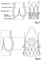
- the anatomical match between the stent and the aortic root is illustrated in Figure 3 .
- the tips of the upper anchoring crown may rest in a final position between the sinutubular junction and the aortic annulus according to Figure 3 and press on the pushed back native valve leaflets.
- the shaded box in Figure 4 indicates the range of the possible location for the coronary ostia.
- the large openings in between the commissural totems 2 and the arches reduce the risk of coronary flow impairment.
- the frame of the stent does not interfere with the possible need of catheterizing the coronaries.
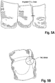
- the aortic bioprosthesis or stented replacement valve 100 comprises a biological component, which may be obtained by selecting and suturing together three Non-Coronary porcine cusps (see e.g ., Figures 5A and B ).
- the biological conduit obtained in this way is trimmed, such as trimmed above the line of insertion of the leaflets ( e.g ., removal of the Valsava sinuses).
- An inner PET-tube may be positioned on the outer surface of the biologic porcine valve and trimmed according to the shape of the biological conduit. The two parts may then be sutured together along the free edges (see Figures 6A and B ).
- a manufacturing process related to the assembling of the biological component is disclosed in U.S. Provisional Application No. 61/109,310 and related PCT application WO 2010/049160 , the entire contents of which are incorporated herein by reference it their entireties.
- the bioprosthetic conduit is assembled to the metallic stent, aligning the prosthetic commissures to the commissural totem 2 of the stent and keeping the outflow free edge of the prosthesis above the outward curvature of the upper anchoring crown 3, in order to avoid the reduction of the orifice area of the prosthesis (see Figure 7 ).
- an additional porcine pericardium strip covers the free edge of the valve outflow tract ( Figure 8 ).
- the inner PET-skirt reinforces the biological tissue in the area where stitches fix the valve to the stent struts.
- the pericardium strip protects the valve leaflets from direct contact with the stitches of the finishing hem at the distal hedge of the valve.
- the outer PET-skirt sutured on the lower anchoring crown contributes to mitigate the risk of paravalvular leakage of the implant.
- the skirt 103 (see Fig. 1 ) is designed to cover the lattice structure or framework of the stent component. In some embodiments, the skirt follows the lattice structure of the lower anchoring crown of the stent component and may be described as a specific atraumatic "flower" design (see, for example, Figure 9 ). The design of the skirt 103 creates a geometrical discontinuity at the inflow edge of the outer fabric skirt. In this way, when the stent is reduced in diameter, due to the oversizing of the prosthesis in respect to annulus/LVOT diameter, the fabric shrinkage doesn't create folds.
- the skirt reduces risk of sharp edges in the framework of the stent that may jeopardize the integrity of the surrounding biological structures (e.g ., mitral anterior leaflet, left bundle branch, etc.).
- the protruding "petals" of the skirt 103 act as soft, dampening elements when bent over the tip of the element forming the lower anchoring crown.
- the overall stent length may be sufficiently small so as to avoid conflict with, for example, the mitral valve when the stent is being used for aortic valve replacement.
- these dimensions will vary depending on, for example, the type of valve used and the dimensions given above are included as examples only and other sizes/ranges are available which conform to the present disclosure.
- a replacement valve for use within a human body includes a valve component, a stent component for housing the valve component, and at least two skirts (e.g ., polyester (PET) skirts).
- An inner skirt may be provided that covers at least a portion ( e.g., all) of an outer surface of the valve component, where the inner skirt may be sutured to at least the inflow tract of the valve component and to an inner surface of the stent.
- An outer skirt may also be provided that is sutured onto an outer surface of the stent.
- An outer PET fabric skirt may be provided in which the free edge of the stent is covered to avoid injuries of the left ventricle wall and mitral valve (see e.g ., Fig.9 ).
- a stent which includes a section for commissural valve fixation which is composed of a plurality ( e.g ., two, three, four, five, six, eight, etc.) longitudinal elements connected on one side to a conically shaped section (for example) used for anchoring towards the left ventricle and on the other side to the conically shaped section (for example) used for stabilization.
- a section for commissural valve fixation which is composed of a plurality (e.g ., two, three, four, five, six, eight, etc.) longitudinal elements connected on one side to a conically shaped section (for example) used for anchoring towards the left ventricle and on the other side to the conically shaped section (for example) used for stabilization.
- the stent is designed to better match the size and shape of a biological valve with narrow commissural posts 2 and, in some embodiments, allow a more robust suturing of the valve commissural posts to the stent.
- Narrow commissural posts 2 may improve the perfusion of the coronary arteries via the sinus of vasalva.
- an additional reinforcement crown may be added as well in some embodiments.
- the stent design allowing for the fixation of the valve commissural posts 2 provides a further advantage, as the size and shape of such stents preferably does not change substantially, and does not change during a required crimping process for loading the stent (with valve, "valved-stent") onto a delivery device. Accordingly, this may reduce (and preferably does reduce) the risks of suture damage and facilitating crimping and subsequently releasing of the valved-stent (for example).
- Figures 2B to 2D are provided to illustrate the dimensions of the stent component.
- D3 represents the diameter of the most proximal edge of the stent component in the expanded configuration.
- D2 represents the diameter of the stent component at the juncture between the upper and lower anchoring crowns.
- H2 represents the axial distance between the planes of the diameters D2 and D3 in the expanded configuration.
- D1 represents the diameter of the most distal edge of the upper anchoring crown of the stent component in the expanded configuration.
- H1 represents the axial distance between the planes of the diameters D1 and D2 in the expanded configuration.
- the length of H2 may be between about 3 to about 15 mm ( e.g ., about 3 mm, about 4 mm, about 5 mm, about 6 mm, about 7 mm, about 8 mm, about 9 mm, about 10 mm, about 11 mm, about 12 mm, about 13 mm, about 14 mm, and about 15 mm).
- the length of H2 may been adjusted depending on the intended application of the stent of stent-valve.
- the length of H2 may range from about 3 to about 5 mm, about 3 to about 7 mm, about 3 to about 12 mm, about 3 to about 15 mm, about 3 to about 20 mm, about 5 to about 10 mm, about 5 to about 12 mm, about 5 to about 15 mm, about 7 to about 10 mm, about 7 to about 12 mm, about 7 to about 15 mm, about 10 to about 13 mm, about 10 to about 15 mm, or about 7 to about 20 mm.
- the length of this section may be on the smaller end of the scale to avoid potential conflict with a cardiac valve, such as the mitral valve.
- the diameter at D3 may be between about 22 mm to about 40 mm ( e.g ., about 22 mm, about 23 mm, about 24 mm, about 25 mm, about 26 mm, about 27 mm, about 28 mm, about 29 mm, about 30 mm, about 31 mm, about 32 mm, about 33 mm, about 34 mm, about 35 mm, about 36 mm, about 37 mm, about 38 mm, about 39 mm, and about 40 mm).
- This diameter D3 may been adjusted depending on the intended application of the stent of stent-valve.
- the diameter D3 in the expanded configuration may be from between about 15 mm to about 50 mm, from between about 15 mm to about 40 mm, from between about 20 mm to about 40 mm, from between about 24 mm to about 40 mm, from between about 26 mm to about 40 mm, from between about 28 mm to about 40 mm, from between about 30 mm to about 40 mm, from between about 32 mm to about 40 mm, from between about 34 mm to about 40 mm, from between about 36 mm to about 40 mm, from between about 38 mm to about 40 mm, from between about 22 mm to about 38 mm, from between about 22 mm to about 36 mm, from between about 22 mm to about 34 mm, from between about 22 mm to about 32 mm, from between about 22 mm to about 30 mm, from between about 22 mm to about 28 mm, from between about 24 mm to about 34 mm, from between about 25 mm to about 35 mm, or from between about 25 mm to about 30 mm.
- the diameter of the stent component D2 may be between about 20 mm to about 30 mm ( e.g ., about 20 mm, about 21 mm, about 22 mm, about 23 mm, about 24 mm, about 25 mm, about 26 mm, about 27 mm, about 28 mm, about 29 mm, and about 30 mm).
- This diameter of the stent component D2 may been adjusted depending on the intended application of the stent of stent-valve. For example, this diameter of the stent component D2 may be sized according to the shape of the annulus of the cardiac valve.
- the diameter of the stent component D2 may be from between about 15 mm to about 40 mm, from between about 15 mm to about 30 mm, from between about 18 mm to about 35 mm, from between about 22 mm to about 30 mm, from between about 24 mm to about 30 mm, from between about 26 mm to about 30 mm, from between about 28 mm to about 30 mm, from between about 22 mm to about 28 mm, from between about 22 mm to about 26 mm, from between about 20 mm to about 24 mm, from between about 20 mm to about 26 mm, from between about 20 mm to about 28 mm, and from between about 22 mm to about 32 mm.
- the diameter D1 may be between about 22 mm to about 40 mm ( e.g ., about 22 mm, about 23 mm, about 24 mm, about 25 mm, about 26 mm, about 27 mm, about 28 mm, about 29 mm, about 30 mm, about 31 mm, about 32 mm, about 33 mm, 34 mm, 35 mm, 36 mm, 37 mm, about 38 mm, about 39 mm, and about 40 mm). This diameter D1 may been adjusted depending on the intended application of the stent of stent-valve.
- the diameter in the expanded configuration D1 may be from between about 15 mm to about 50 mm, from between about 15 mm to about 40 mm, from between about 20 mm to about 40 mm, from between about 24 mm to about 40 mm, from between about 26 mm to about 40 mm, from between about 28 mm to about 40 mm, from between about 30 mm to about 40 mm, from between about 32 mm to about 40 mm, from between about 34 mm to about 40 mm, from between about 36 mm to about 40 mm, from between about 38 mm to about 40 mm, from between about 22 mm to about 38 mm, from between about 22 mm to about 36 mm, from between about 22 mm to about 34 mm, from between about 22 mm to about 32 mm, from between about 22 mm to about 30 mm, from between about 22 mm to about 28 mm, from between about 24 mm to about 34 mm, from between about 25 mm to about 35 mm, or from between about 25 mm to about 30 mm.
- the length of H1 is between about 3 to about 10 mm ( e.g ., about 3 mm, about 4 mm, about 5 mm, about 6 mm, about 7 mm, about 8 mm, about 9 mm, and about 10 mm).
- the length of H1 may be adjusted depending on the intended application of the stent of stent-valve.
- the length of H2 may range from about 3 to about 5 mm, about 3 to about 15 mm, about 3 to about 20 mm, about 5 to about 10 mm, about 7 to about 10 mm, about 7 to about 12 mm, about 7 to about 15 mm, about 10 to about 13 mm, about 5 to about 15 mm, about 7 to about 20 mm.
- the length of this section may be on the smaller end of the scale to avoid potential conflict with the sinus of Valsalva.
- Figure 2D is provided to illustrate the angles of the anchoring crowns.
- the ⁇ 1 angle defines the angle of the upper anchoring crown of the stent component in the expanded configuration.
- the ⁇ 2 angle defines the angle of the lower anchoring crown of the stent component in the expanded configuration.
- the ⁇ 3 angle defines the angle of bending of the tip, which is done so as to prevent injuries of sinus.
- the ⁇ 1 angle may be between from about 0 degree to about 90 degree (e.g ., about 10 degree, about 15 degree, about 20 degree, about 25 degree, about 30 degree, about 35 degree, about 40 degree, about 45 degree, about 50 degree, about 55 degree, about 60 degree, about 65 degree, about 70 degree, about 75 degree, and about 80 degree).
- the ⁇ 1 angle may be between from about 20 degree to about 70 degree, most preferable between from about 30 degree to about 60 degree.
- the ⁇ 1 angle is between from about 20 degree to about 80 degree, between from about 20 degree to about 60 degree, between from about 20 degree to about 50 degree, between from about 20 degree to about 45 degree, between from about 40 degree to about 60 degree, between from about 45 degree to about 60 degree, between from about 30 degree to about 50 degree, between from about 30 degree to about 45 degree, between from about 30 degree to about 40 degree, or between from about 25 degree to about 45 degree.
- the ⁇ 2 angle may be between from about 0 degree to about 50 degree (e.g ., about 5 degree, about 10 degree, about 15 degree, about 20 degree, about 25 degree, about 30 degree, about 35 degree, about 40 degree, about 45 degree, and about 50 degree).
- the ⁇ 2 angle may be between from about 10 degree to about 40 degree, most preferable between from about 10 degree to about 30 degree.
- the ⁇ 2 angle is between from about 5 degree to about 45 degree, between from about 5 degree to about 40 degree, between from about 5 degree to about 30 degree, between from about 5 degree to about 25 degree, between from about 5 degree to about 20 degree, between from about 5 degree to about 15 degree, between from about 10 degree to about 20 degree, between from about 10 degree to about 25 degree, between from about 10 degree to about 30 degree, between from about 10 degree to about 40 degree, between from about 10 degree to about 45 degree, between from about 15 degree to about 40 degree, between from about 15 degree to about 30 degree, between from about 15 degree to about 25 degree, between from about 20 degree to about 45 degree, between from about 20 degree to about 40 degree, or between from about 20 degree to about 30 degree
- the ⁇ 3 angle may be between from about 0 degree to about 180 degree (e.g ., about 5 degree, about 10 degree, about 15 degree, about 20 degree, about 25 degree, about 30 degree, about 35 degree, about 40 degree, about 45 degree, about 50 degree, about 55 degree, about 60 degree, about 65 degree, about 70 degree, about 75 degree, about 80 degree, about 85 degree, about 90 degree, about 95 degree, about 100 degree, about 105 degree, about 110 degree, about 115 degree, about 120 degree, about 125 degree, about 130 degree, about 135 degree, about 140 degree, about 145 degree, about 150 degree, about 155 degree, about 160 degree, about 165 degree, about 170 degree, about 175 degree, and about 180 degree).
- the ⁇ 3 angle is between from about 45 degree to about 90 degree, between from about 45 degree to about 180 degree, between from about 60 degree to about 90 degree, between from about 45 degree to about 120 degree, between from about 60 degree to about 120 degree, between from about 90 degree to about 120 degree, between from about 90 degree to about 180 degree, or between from about 120 degree to about 180 degree.
- the length of the upper anchoring crown 3 and commissural posts section 2 of the stent component H3 is between about 3 to about 50 mm ( e.g ., about 3 mm, about 4 mm, about 5 mm, about 6 mm, about 7 mm, about 8 mm, about 9 mm, about 10 mm, about 11 mm, about 12 mm, about 13 mm, about 14 mm, about 15 mm, about 20 mm, about 22 mm, about 24 mm, about 25 mm, about 26 mm, about 28 mm, about 30 mm, about 32 mm, about 34 mm, about 36 mm, about 38 mm, about 40 mm, about 42 mm, about 44 mm, about 45 mm, about 46 mm, about 48 mm, and about 50 mm).
- the length of H3 may been adjusted depending on the intended application of the stent of stent-valve.
- the length of H3 may range from about 3 to about 40 mm, about 3 to about 30 mm, about 3 to about 20 mm, about 3 to about 10 mm, about 10 to about 50 mm, about 10 to about 40 mm, about 10 to about 30 mm, about 10 to about 20 mm, about 15 to about 50 mm, about 15 to about 40 mm, about 15 to about 30 mm, about 20 to about 50 mm, about 20 to about 40 mm, about 20 to about 30 mm, about 15 to about 50 mm, about 25 to about 50 mm, about 30 to about 50 mm, about 40 to about 50 mm, about 15 to about 40 mm, about 25 to about 40 mm, or about 30 to about 40 mm.
- the length of the stabilization arches 1 of the stent component H4 is between about 5 to about 50 mm ( e.g ., about 5 mm, about 6 mm, about 7 mm, about 8 mm, about 9 mm, about 10 mm, about 11 mm, about 12 mm, about 13 mm, about 14 mm, about 15 mm, about 20 mm, about 22 mm, about 24 mm, about 25 mm, about 26 mm, about 28 mm, about 30 mm, about 32 mm, about 34 mm, about 36 mm, about 38 mm, about 40 mm, about 42 mm, about 44 mm, about 45 mm, about 46 mm, about 48 mm, and about 50 mm).
- the length of H4 may been adjusted depending on the intended application of the stent of stent-valve.
- the length of H4 may range from about 5 to about 40 mm, about 5 to about 30 mm, about 5 to about 20 mm, about 5 to about 10 mm, about 10 to about 50 mm, about 10 to about 40 mm, about 10 to about 30 mm, about 10 to about 20 mm, about 15 to about 50 mm, about 15 to about 40 mm, about 15 to about 30 mm, about 20 to about 50 mm, about 20 to about 40 mm, about 20 to about 30 mm, about 15 to about 50 mm, about 25 to about 50 mm, about 30 to about 50 mm, about 40 to about 50 mm, about 15 to about 40 mm, about 25 to about 40 mm, or about 30 to about 40 mm.
- the ⁇ 4 and ⁇ 5 angles represent the offset angle from a longitudinal axis of the stabilization arches 1 of the stent component in the expanded configuration. If the stabilization arches are directed away from the center of the stent, the ⁇ 4 angle is used. If or where the stabilization arches are directed toward the center of the stent, the ⁇ 5 angle is used.
- the ⁇ 4 angle is preferably between from about 0 degree to about 60 degree (e.g ., about 5 degree, about 10 degree, about 15 degree, about 20 degree, about 25 degree, about 30 degree, about 35 degree, about 40 degree, about 45 degree, about 50 degree, about 55 degree, and about 60 degree). According to some embodiments, the ⁇ 4 angle is between from about 20 degree to about 60 degree, between from about 30 degree to about 60 degree, between from about 40 degree to about 60 degree, between from about 45 degree to about 60 degree, between from about 30 degree to about 50 degree, between from about 30 degree to about 45 degree, between from about 20 degree to about 40 degree, or between from about 15 degree to about 45 degree.
- the ⁇ 5 angle is preferably between from about 0 degree to about 20 degree ( e.g ., about 5 degree, about 10 degree, about 15 degree, and about 20 degree). According to some embodiments, the ⁇ 5 angle is between from about 5 degree to about 20 degree, between from about 10 degree to about 20 degree, between from about 15 degree to about 20 degree, between from about 0 degree to about 15 degree, between from about 0 degree to about 10 degree, between from about 5 degree to about 15 degree, between from about 10 degree to about 15 degree, or between from about 10 degree to about 20 degree.
- the stent components of the stent-valves may be classified into different categories of sizes, such as small, medium, and large.
- the stent components may be sized as small, medium, and large according the following table.
- a replacement valve comprising a valve component and a stent component, wherein the stent component comprises a lower anchoring crown, an upper anchoring crown, a commissural post section, and stabilization arches.
- the conical body of the lower anchoring crown may slope outwardly from an inner diameter D2 to an outer diameter D3 in the direction of the proximal end, wherein the inner diameter D2 may be between about 20 mm to about 27 mm, especially between 20 mm to about 25 mm and wherein the outer diameter D3 may be between about 26 mm to about 33 mm, especially between 26 mm and 32 mm.
- the axial distance between the planes of the diameters D2 and D3 in the expanded configuration (H2) may be between about 7 to about 11 mm, wherein the outward slope of the lower anchoring crown is defined by an angle ⁇ 2, which may be between from about 15 degree to about 25 degree.
- the conical body of the upper anchoring crown may slope outwardly from an inner diameter D2 to an outer diameter D1 in the direction of the distal end, wherein the inner diameter D2 may be between about 20 mm to about 27 mm, especially between 20 mm and 25 mm, and wherein the outer diameter D1 may be between about 26 mm to about 33 mm, especially between 26 mm and 31 mm.
- the axial distance between the planes of the diameters D2 and D1 in the expanded configuration (H1) may be between about 4 to about 8 mm.
- the outward slope of the lower anchoring crown may be defined by an angle ⁇ 1, which may be between from about 45 degree to about 65 degree.
- the end of the upper anchoring crown may form a tip, wherein the tip is bent inwardly toward the longitudinal axis at an angle ⁇ 3.
- the angle ⁇ 3 may be between from about 45 degree to about 65 degree.
- the length of the combined upper anchoring crown and commissural posts of the stent component (H3) may be between about 11 to about 15 mm.
- the length of the stabilization arches of the stent component (H4) may be between about 14 to about 30 mm (preferably up to about 22 mm); wherein the stabilization arches of the stent component expands outwardly at an angle ⁇ 4 from a longitudinal axis toward the second distal end of the replacement valve.
- the angle ⁇ 4 may be between about 5 degree to about 15 degree.
- a replacement valve comprising a valve component and a stent component, wherein the stent component comprises a lower anchoring crown, an upper anchoring crown, a commissural post section, and stabilization arches.
- the conical body of the lower anchoring crown may slope outwardly from an inner diameter D2 to an outer diameter D3 in the direction of the proximal end.
- the inner diameter D2 may be between about 21 mm to about 26 mm
- the outer diameter D3 may be between about 27 mm to about 33 mm.
- the axial distance between the planes of the diameters D2 and D3 in the expanded configuration (H2) may be between about 8 to about 12 mm.
- the outward slope of the lower anchoring crown may be defined by an angle ⁇ 2, which may be between from about 15 degree to about 25 degree.
- the conical body of the upper anchoring crown may slope outwardly from an inner diameter D2 to an outer diameter D1 in the direction of the distal end.
- the inner diameter D2 may be between about 21 mm to about 26 mm
- the outer diameter D1 may be between about 27 mm to about 32 mm.
- the axial distance between the planes of the diameters D2 and D1 in the expanded configuration (H1) may be between about 4 to about 8 mm.
- the outward slope of the lower anchoring crown is defined by an angle ⁇ 1, which may be between from about 45 degree to about 65 degree.
- the end of the upper anchoring crown forms a tip, wherein the tip is bent inwardly toward the longitudinal axis at an angle ⁇ 3, which may be between from about 45 degree to about 65 degree.
- the length of the combined upper anchoring crown and commissural posts section of the stent component (H3) may be between about 13 to about 17 mm.
- the length of the stabilization arches and of the stent component (H4) may be between about 15 to about 23 mm.
- the stabilization arches of the stent component expand outwardly at an angle ⁇ 4 from a longitudinal axis toward the second distal end of the replacement valve. The angle ⁇ 4 is between about 5 degree to about 15 degree.
- a replacement valve comprising a valve component and a stent component, wherein the stent component comprises a lower anchoring crown, an upper anchoring crown, a commissural post section, and stabilization arches.
- the conical body of the lower anchoring crown may slope outwardly from an inner diameter D2 to an outer diameter D3 in the direction of the proximal end.
- the inner diameter D2 may be between about 22 mm to about 27 mm
- the outer diameter D3 may be between about 28 mm to about 34 mm
- the axial distance between the planes of the diameters D2 and D3 in the expanded configuration (H2) may be between about 9 to about 13 mm.
- the outward slope of the lower anchoring crown may be defined by an angle ⁇ 2, and wherein ⁇ 2 is between from about 15 degree to about 25 degree.
- the conical body of the upper anchoring crown slopes outwardly from an inner diameter D2 to an outer diameter D1 in the direction of the distal end, wherein the inner diameter D2 may be between about 22 mm to about 27 mm, and wherein the outer diameter D1 may be between about 28 mm to about 33 mm.
- the axial distance between the planes of the diameters D2 and D1 in the expanded configuration (H1) may be between about 4 to about 8 mm; wherein the outward slope of the lower anchoring crown is defined by an angle ⁇ 1, which may be between from about 45 degree to about 65 degree.
- the end of the upper anchoring crown may form a tip, wherein the tip is bent inwardly toward the longitudinal axis at an angle ⁇ 3, which may be between from about 45 degree to about 65 degree.
- the length of the combined upper anchoring crown and commissural post section of the stent component (H3) may be between about 15 to about 19 mm.
- the length of the stabilization arches and of the stent component (H4) may be between about 16 to about 24 mm.
- the stabilization arches of the stent component expands outwardly at an angle ⁇ 4 from a longitudinal axis toward the second distal end of the replacement valve, wherein ⁇ 4 is between about 5 degree to about 15 degree.
- multiple fixation elements e.g., 2 or more, 3 or more, 4 or more, 5 or more, 6 or more, 7 or more, 8 or more, 9 or more, 10 or more, 11 or more, 12 or more, 13 or more, 14 or more, 15 or more, 16 or more, 17 or more, 18 or more, 19 or more, 20 or more, etc. or 2 to 5, 2 to 10, 2 to 20, 2 to 30, 2 to 40, etc.
- a matching/complimentary element e.g ., stent holder with pins
- the design of the multiple fixation elements may allow for the fixation of the stent onto the catheter only when the stent is crimped.
- the fixation may release automatically when the stent starts to expand. That is, the shape of the stent in the unexpanded state is designed to have holes or free areas that can be used to couple the stent with a stent holder.
- the expanded configuration is absent such holes or free spaces and thus the stent automatically becomes uncoupled or releases from the stent holder upon expansion.
- the stent component may further include at least one or a plurality (e.g., 2, 3, 4, 5, 6, 7, 8, 9, 10, etc.) of attachment elements at the proximal end of the stent, wherein the attachments elements are capable of mating with a stent holder 560 of a delivery device 500 (see Fig. 10 and 12 ).
- the attachment elements may include a crochet-like configuration that engages, for example, a groove or other opening within the stent holder 560.
- Such attachment elements may be formed in the shape of a bent, or curved angled member ( e.g ., an " " or " “ like shape). See FIG 2D .
- such attachment elements may be a hook (e.g., a "J" like shape).
- the attachment element may be provided in an angled shape, for example, that extends from the body of the stent inwardly toward a central, longitudinal axis of the stent.
- the opening in the stent holder 560 e.g., groove
- the opening in the stent holder 560 may allow for a safe release of the stent upon rotation of the delivery system (e.g., a portion, all or members thereof - e.g., rotation of the stent holder).
- the end of the attachment element slides onto a surface (e.g. a ramp extending in the circumferential direction) and is thereby forced, according to some embodiments, to disengage the stent holder when reaching an edge (e.g. radially outermost end of ramp).
- FIG. 2E there is a cylindrical section 16 between the upper conical crown 13 and the lower conical crown 14.
- the cylindrical section 16 may further extend to form commissural posts, such that the axial profile shows a further cylindrical section 17 between the upper conical crown 13 and the stabilisation arches 11.
- the distal part 18 of the stabilisation arches 11 is inclined inwardly, such that the arms of the stabilisation arches 11 are bulged to allow the distal stent section adapting at the inside of the aorta.
- the stent components of the stent-valves may be classified into different categories of sizes, such as small, medium, and large.
- the stent components may be sized as small, medium, and large according the following table.
- D3 represents the diameter of the most proximal edge of the stent component in the expanded configuration
- D2 represents the diameter of the stent component at the cylindrical section between the upper and lower anchoring crowns in the expanded configuration.
- D4 represents the diameter of the stent component at the junction between the outwardly and inwardly bent sections of the stabilization arches in the expanded configuration
- D5 represents the diameter of the stent component at the most distal edge of the stent in the expanded configuration.
- L1 represents the axial length of the inwardly bent part of the stabilization arches.
- L2 represents the axial length of the outwardly sloping part of the stabilization arches.
- L3 represents the axial length of the cylindrical section between the upper anchoring crown and the stabilization arches.
- L4 represents the axial length of the conical part of the upper anchoring crown in the expanded configuration.
- L5 represents the axial length of the trunk section between conical part of the upper anchoring crown and the conical part of the lower anchoring crown.
- L6 represents the axial length of the outwardly sloping conical part of the lower anchoring crown in the expanded configuration.
- L7 represents the axial length of the proximal cylindrical part of the lower conical crown.
- L8 represents the axial length of the axial extensions forming attachment elements.
- L9 represents the axial length of the cylindrical section between the stabilization arches and the lower conical crown. The total length L10 of the stent thus results in a range of 41 mm to 49 mm.
- Figure 2F shows in comparison a first embodiment according to Table 1 (in dashed lines) and a second preferred embodiment according to Table 2 in plain lines.
- a stent according to the second preferred embodiment may sit lower within the native valve as compared to the first embodiment and thus the commissural posts including the valve of the second preferred embodiment rests closer to the native annulus.
- some embodiments of the stent component may allow for self-positioning of the replacement valve under diastolic pressure. Once delivered slightly above the aortic annulus, the stent-valve migrates toward the left ventricle due to the forces caused by the diastolic pressure until it reaches a stable position given by the shape / radial force of the anchoring crowns, the compliance of the aortic annulus, and presence of any calcification.
- the presence of calcification deposits at the native valve may limit or prevent sliding movement of the valve from a release position to a different stable position.
- the stable position may be the same as the release position.
- a stent-valve suitable for implanting at a calcified native valve site comprises an upper (first) crown section comprising at least a portion diverging outwardly in a direction towards an aortic end of the stent-valve.
- the upper crown section may have a free end (e.g. proximal of the distal end of the stent component).
- the upper crown/divergent portion may have an angle of divergence (or inclination or conical angle) with respect to the stent axis of less than 60 degrees (preferably 50 degrees or less, preferably 45 degrees or less, for example 43-45 degrees) and/or have an axial length of less than 10mm (preferably less than 8mm, preferably less than 6mm, preferably less than 5 mm, for example, 3-4 mm).
- Such dimensions may be regarded as less sculpted than in some other designs.
- the dimensions can nevertheless provide a reliable abutment surface to resist migration of the stent-valve towards the ventricle during ventricular diastole, without the upper crown being so large and/or having an aggressive angle of inclination that the positioning is likely to be affected adversely by the calcified deposits.
- a stent-valve suitable for implanting at a calcified valve site comprises an upper (first) crown comprising at least a portion diverging outwardly in a direction towards an aortic end of the stent-valve.
- a substantially non-diverging region 16 (see e.g. Fig 2E ) communicating with the narrow end of the diverging portion may extend therefrom in a direction towards the ventricular end of the stent-valve.
- substantially non-diverging may mean a divergence of no more than 10 degrees, preferably less than 8 degrees, preferably less than 6 degrees, preferably less than 5 degrees, preferably less than 4 degrees, and preferably zero degrees.
- the substantially non-diverging region may have an axial length L5 (see Fig. 2E ) of at least 1mm, preferably at least 2mm, preferably at least 3mm, preferably at least 4mm, for example, 4.5-5.5mm. Provision of such a substantially non-diverging region may enable the stent-valve to better accommodate calcified deposits where the stent-valve passes through the native valve and/or native annulus.
- the substantially non-diverging region may separate (at least a portion of) the upper (first) crown from (at least a portion of) the lower (second) crown.
- the substantially non-diverging section may form a part of the upper crown section and/or lower crown section.
- a stent-valve suitable for implanting at a calcified valve site comprises a lower crown section.
- the lower crown section may comprise at least a portion diverging outwardly in a direction towards the ventricular end of the stent valve.
- the lower crown and/or divergent portion may be provided at a portion of the stent-valve intended to be received at the ventricle, for engaging native tissue to resist migration of the stent-valve in a direction out of the ventricle.
- the divergent portion of the lower crown section may have an angle of divergence with respect to the stent-valve axis of between 10 degrees and 20 degrees (preferably 10-16 degrees, more preferably 10-15 degrees, more preferably 10-14 degrees, more preferably 10-13 degrees).
- Such an angle of divergence may be regarded as less sculpted than some other designs (see e.g. the embodiment in Figure 2H shown in continuous line as compared to the embodiment in dashed lines).
- the angle permits the lower crown to function to resist migration, while being versatile in accommodating a wide range of calcifications without affecting function.
- an upper crown of a stent-valve is provided that is not too large (see e.g. the embodiment in Figure 2H shown in continuous line as compared to the embodiment in dashed lines having a larger crown), the axial length L4 being between 3 and 4 mm and the angle ⁇ 1 of the upper crown being between 43° and 45°, as well as the length of the cylindrical part 16 being not too small, the length L5 being between 4.5-5.5 mm.
- Stents of this type do not block the coronary arteries or contact the sinus of the Vasalva, they reduce the risk of coronary occlusion and they even fit to a calcified annulus.
- the lower crown comprises a relatively small conical angle of about 10° to about 13° and a cylindrical proximal section with an axial length of about 1-2 mm. Stents of this type allow a homogeneous seating towards a calcified annulus and less turbulences within the valve inflow.
- the stent stabilization arches 11 are bent inwardly with a relatively big radius of the curvature to avoid injuries of the ascending aorta.
- Figure 2F shows a comparison of different embodiments in a side view.
- the side view pictured in dashed lines represents a first embodiment corresponding to Table 1 and Figures 2A-2D .
- the side view shown in a continuous line represents a second preferred embodiment corresponding to Table 2 and Figure 2E .
- the lower anchoring crown 14 may have axial extensions 19 each forming a respective attachment element.
- the attachment element comprises an opening for receiving a pin arranged on the stent holder of the delivery system.
- the lower anchoring crown comprises cells 20 and the extension is formed by an elongation 21 of at least one cell 22 as shown in figure 2G .
- the upper part of figure 2G shows a side view of cells of the lower anchoring crown in a non expanded configuration.
- the elongation 21 of the cell 22 defines an opening 23 for engagement with a pin 82.
- the aperture size (e.g., diameter O) of the opening 23 enlarges as shown in the lower part of figure 2G .
- the elongation 21 may be received by an axial groove arranged on the stent holder of the delivery system.
- Figure 2H shows a side view of a stabilization arch 111 of a specific embodiment.
- one arm 126 of the arch 111 comprises a pattern 125, in this case two kinks, such that the arm 126 is different from the other arm 127 of the arch 111 and may be distinguished from the other arm 127 in a projected image, such as an x-ray image.
- a valved-stent delivery system, and method for delivering the valved-stent to an implantation site are provided in which the valved-sent is expanded at the implantation site in a stepwise manner (for example) from its distal end towards its proximal end.
- a release procedure for causing expansion of a valved-stent may involve pulling back a sheath element on a catheter delivery device.
- the sheath element constrains the valved-stent toward a section of the heart (for example, the left ventricle of the heart). According to such a procedure, there may be no interaction of the delivery system with the anatomy of the ascending aorta/aortic arch.
- the sheath constraining the valved-stent, and the tip of the delivery system may not be required to enter the aortic arch during the release procedure, which is beneficial since such entry potentially can cause a bending moment acting onto the valved-stent and result in inaccurate positioning of the valved-stent (e.g., tilting).
- a replacement heart valve comprising: a valve component; and a stent component to which the valve component is affixed thereto, the stent component comprising: a longitudinal axis; a lower anchoring crown including a substantially conical shape having a narrow end, a broad end and a predetermined first height; and an upper anchoring crown including a substantially conical shape having a narrow end, a broad end and a predetermined second height, wherein: a center of each of the lower anchoring crown and upper anchoring crown are arranged to align substantially with the longitudinal axis; the narrow ends of the lower and upper anchoring crowns are arranged to meet forming an annular groove to receive the annulus of a failed heart valve at an implantation site of the heart, and the first height of the lower anchoring crown is greater than the second height of the upper anchoring crown.
- Figure 2I illustrates two examples of aortic bioprosthesis or stented replacement valves 100 and 100' according to some embodiments.
- the upper anchoring crown 3, 13 and the lower anchoring crown 4, 14 meet at a line L, from where the commissural posts 2, 12 extend.
- the curvature 31 between two adjacent stabilization arches 11 corresponds to a radius which is much smaller than the curvature 32 at the tip of the stabilization arches 11.
- the arches 11 extend more upwardly than outwardly from the commissural posts 12 and the risk of contacting tissue in this region is reduced.
- the thickness 33 of material of the stabilization arch at its base near the section where it communicates with the commissural posts 12 is smaller than the material thickness 34 at the tip 23'.
- the tips 23' of the stabilization arches 11 turn at least partly towards the central axis of the stent.
- the stabilization arch 11 in its entire lengths may be divergent but with reduced divergence at the tip 23' portion.
- the stabilization arches 11 have a shovel-shape like envelope, which on the one hand supports positioning of the stent and the other hand reduces the risk of injuring the surrounding tissue.
- the present invention is related to a delivery system for delivering the stent-valves of the present invention.
- the cardiac stent-valve delivery system may include an inner assembly and an outer assembly.
- the inner assembly may include a guide wire lumen (e.g., polymeric tubing) and a stent holder for removable attachment to a stent-valve.
- the outer assembly may include a sheath.
- the inner member and the outer member may be co-axially positioned and slidable relative to one another in order to transition from a closed position to an open position, such that in the closed position the sheath encompasses the stent-valve still attached to the stent holder and thus constrains expansion of the stent-valve. In the open position, the outer sheath may not constrain expansion of the stent-valve and thus the stent-valve may detach from the stent holder and expand to a fully expanded configuration.
- FIGS 10-14 illustrate the delivery device 500.
- the delivery system allows for a minimally-invasive surgical approach whereby valve replacement surgery is performed on a beating heart without the need for an open-chest cavity and heart-lung bypass.
- the heart is for example penetrated trans-apically through a relatively small opening in the patient's chest (e.g., an intercostal space - a region between two ribs). From this access point, the left ventricle is penetrated at the apex of the heart.
- the delivery device 500 is used to position and release the aortic bioprosthesis or stented replacement valve 100 at the intended location over the patient's native, calcified aortic valve via transapical access.
- the delivery system may comprise the following components: a flexible inner member 552; flexible outer member 554; and a release handle 501.
- the flexible inner member 552 for example contains a guide wire lumen bonded proximally to a female luer lock and distally to a radio-opaque atraumatic tip 556.
- the flexible inner member 552 may further comprise a stent holder, which may be added to avoid premature delivery of the aortic bioprosthesis during the release procedure.
- the flexible inner member 552 may further comprise a radio-opaque markerband for the accurate positioning of the implant.
- the inner member is fixed proximally to the release handle
- the flexible outer member 554 for example contains distally the compressed aortic bioprosthesis and is fixed proximally to the trigger of the release handle. Both flexible members may be coaxially arranged and longitudinally slideable.
- the delivery device 500 for example comprises a release handle 501, which provides an ergonomic fit to the physician's hand to facilitate the deployment of the aortic bioprosthesis 100.
- the delivery device 500 may comprise one or more of the following features (see Fig. 11 ): Check valve 520 for flushing of the annular space between the inner and outer member; Safety button 510 to avoid premature release of the implant; Release button 505 to allow partial / full release of the implant; and Trigger 520 for releasing the aortic bioprosthesis from the delivery system.
- the delivery system for example has a crossing profile of 33F, a usable length of min. 330mm, and is compatible with .035" guide wires.
- the delivery system accepts all the different sizes of the aortic bioprosthesis or stented replacement valve 100.
- the device preparation before use may comprise one or more of the following optional preparation steps: Rinsing the stent-valve 100 in 4 different baths containing 500ml of sterile saline solution during a minimum of 3min in each bath (min. total 12min rinsing duration) to remove residuals of the sterilant solution; Crimping the stent-valve 100 onto the Transapical Delivery System by means of a crimper ( e.g ., MSI crimper HV200-104-40); and Flushing of the delivery system.
- a crimper e.g ., MSI crimper HV200-104-40
- the delivery system might be inserted over the wire into the left ventricle.
- An introducer sheath may optionally be used through which the delivery device is inserted.
- the outer member 554 ( Fig. 12 ) of the delivery device may have a generally uniform diameter along at least the portion of its length intended to be inserted. Such a uniform diameter may enable the delivery device to be inserted into the left ventricle without the need for an additional introducer sheath. Avoiding an introducer sheath may enable a smaller puncture aperture in the ventricle wall, because the puncture does not need to accommodate a wall thickness of an introducer sheath in addition to the delivery device.
- the following exemplary steps may be performed in order to release the stent-valve 100: Unscrewing and removal of the safety button; Fluoroscopic positioning of the crimped stent-valve 100 at the intended location by mean of the radioopaque markerband located onto the inner member ( e.g ., at the level of the groove D2); Partial delivery of the stent-valve 100 under fluoroscopic control by pulling back the trigger with the release button 505 in "partial release” position ( Fig. 13 ). At this stage, the stabilization arches are fully deployed and the upper anchoring crown partially or fully deployed.
- Pulling back of the trigger 520 causes a backward movement of the outer member relative to the inner member and thus a partial delivery of the implant; Final delivery of the partially deployed stent-valve 100 under fluoroscopic control upon appropriate positioning by pulling back the trigger with the release button in "full release” position ( Fig. 14 ).
- the stent-valve 100 When deployed, the stent-valve 100 automatically detaches from the stent holder due to the self expandable properties of the stent thereby leaving the upper and lower crown fully expanding over the native leaflets respectively within the left ventricle outflow tract. Careful withdrawal of the delivery system tip 556 through the fully deployed and functional bioprosthesis under fluoroscopic control to avoid any valve dislodgement.
- the delivery system may be closed by pushing forward the trigger and withdrawal of the delivery system through the sheath introducer.
- FIG. 10-12 shows a delivery system 500 for distal-to-proximal expansion of a stent-valve 100.
- the system 500 may include an inner member 552 and an outer member 554 (e.g., sheath) which are co-axially positioned and slidable one against the other.
- the inner member 552 may comprise tubing (e.g., polymeric tubing) which serves as a guide wire lumen and on which at least one of (and preferably several or all) a tip 556, a fluoroscopic marker 568 (e.g .,radioopaque marker band), and a stent-holder 560 are affixed ( e.g ., bonded).
- the polymeric tubing may be reinforced proximally with a rigid (e.g ., stainless steel) shaft.
- a luer connector may be affixed to a stainless steel shaft to allow flushing of the guide wire lumen with saline (for example).
- the outer member 554 may comprise a distally arranged sheath which may be used to constrain the stent in a closed/contracted ( e.g ., substantially non-expanded) configuration. Proximally, the sheath may be fixed to a hemostasis valve to allow the flushing of the annular space between the inner and outer members with saline (for example).
- the diameter of the outer member 505 may be substantially uniform at least along a portion of its length intended to be inserted through the ventricle wall.
- the diameter of the outer member may vary over its longitudinal direction (e.g ., smaller diameter proximally to decrease the bending stiffness of the delivery system).
- the deployment of the stent-valve may be controlled by pulling back a trigger of or at the delivery device handle.
- the deployment of the stent-valve may occur by holding the inner member at the level of the stainless steel shaft with one hand and the outer member at the level of the hemostasis valve with the other hand. Then, upon positioning of the replacement valve (e.g ., under fluoroscopic control), the outer member is pulled back with the inner member being kept at its original position, until the stent is fully deployed.
- the replacement valve e.g ., under fluoroscopic control
- the movement of the outer member 554 i.e. the valve sheath
- the recapturing mechanism of the delivery device may be activated by turning the recapture control knob 575, which may be placed at the proximal end of the delivery system.
- the bioprosthesis 100 is held in place by inflow hooks (see hooks 5 in Figure 2A ) and/or one or more attachment elements of the bioprosthesis engaging the stent holder 560, while the knob 575, advancing on a thread, slides back the valve sheath to re-close the prosthesis.
- This feature allows either the repositioning or the entire retrieval of the prosthesis from the implant side at any time of the procedure before the final release.
- the tip of the delivery system may be in two parts, which can be easily disconnected.
- the inner part 557 may optionally be of metallic material, while the conical distal part 558 may optionally be of a polymeric material.
- the conical distal part 558 forms the actual tip of the delivery system. With this arrangement, the large tip of the delivery system can be removed whenever it is needed or desired, e.g., during crimping of the stent-valve 100 and/or loading of the crimped stent-valve 100 onto the delivery device.
- a delivery system may comprise a temporary low-profile tip 555 (See Figure 16 ).
- This configuration of the shaft of the delivery system allows the prosthesis 100 to cross easily over the tip during the crimping and/or mounting procedure mentioned above.
- the tip may be rapidly exchanged with a conical tip 558, which may be used for the delivery process.
- the low-profile tip 555 allows the introduction of the shaft thru the prosthesis 100, even when the prosthesis 100 is in a partially collapsed form.
- Advantages of crossing the valve over the tip when the prosthesis 100 is already partially collapsed includes, but is not limited to: better control and direct view of the arrangement of the prosthetic cusps during crimping (since the valve orifice is not occluded by any component), avoiding folds or entrapment of the tissue inside the frames of the stent. Finally, introduction of the smooth low-profile tip further promotes the proper leveling of the cusps, and may cancel the effect of the remaining part of the crimping.
- the inner assembly of the delivery device may include a fluoroscopic marker fixed to the guide wire lumen distal of the stent holderThe diameter of the outer assembly of the delivery device varies over its longitudinal axis.
- the delivery system may comprise a rigid (e.g ., stainless steel) shaft in communication with a proximal end of the guide wire lumen.
- the delivery system comprises a luer connector in communication with the rigid shaft.
- a cardiac stent-valve delivery system may comprise: an inner assembly comprising a guide wire lumen and a stent holder for removable attachment to a stent-valve, wherein the stent-valve comprises at least one attachment element for removable attachment to the stent holder, wherein the at least one attachment element is located at a proximal end of the stent-valve, wherein the proximal end is defined as the end toward the left ventricle when delivered from a transapical approach; and an outer assembly comprising a sheath; wherein the inner member and the outer member are co-axially positioned and slidable relative to one another in order to transition from a closed position to an open position, such that in the closed position the sheath encompasses the stent-valve still attached to the stent holder constraining expansion of the stent-valve, and such that in the open position the outer sheath does not constrain expansion of the stent-valve allowing the stent-valve to
- the guide wire lumen for example comprises polymeric tubing.
- the stent-holder may be fixed (directly or indirectly) relative to the guide wire lumen.
- a fluoroscopic marker may be fixed to the guide wire lumen distal of the stent holder.
- a rigid shaft may be in communication with a proximal end of the guide wire lumen.
- a luer connector may be in communication with the rigid shaft. The diameter of the outer assembly varies over its longitudinal axis.
- a method for replacing an aortic valve within a human body may comprise: covering a stent-valve according to the present invention with a sheath in order to maintain the stent-valve in a collapsed configuration; transapically inserting the stent-valve still in the collapsed configuration into the human body; partially expanding the stent-valve by sliding the sheath towards the left ventricle of the heart, wherein said sliding of the sheath towards the left ventricle causes expansion of a distal end of the stent-valve while the proximal end of the stent-valve remains constrained by the sheath; and further sliding the sheath towards the left ventricle of the heart in order to substantially release the entire stent-valve such that the stent-valve is allowed to expand to an expanded configuration.
- the method may further comprise sliding the sheath in the opposite direction prior to said full expansion in order to recapture the stent-valve within the sheath.
- a method for cardiac valve replacement may comprise: releasing a distal end of a stent-valve according to the present invention from a sheath, wherein the distal end comprises a radiopaque marker; rotating the stent-valve, if necessary, to orient the stent-valve appropriately with respect to the coronary arteries; releasing stabilization arches of the stent-valve from the sheath, in order to cause at least one of the stabilization arches to contact the aorta; releasing an upper anchoring crown 3 of the stent-valve from the sheath, in order to cause the lower anchoring crown to contact native valve leaflets; and releasing a lower anchoring crown 4 of the stent-valve from the sheath, in order to cause the lower anchoring crown 4 to contact an annulus/inflow tract, wherein the lower anchoring crown 4 comprises the proximal section of the stent-valve and said releasing of the lower anchoring crown 4 comprises fully releasing the stent-valve
- the method for cardiac valve replacement may comprisee: releasing a distal end of a valved-stent according to the present invention from a sheath, wherein the distal end comprises a radiopaque marker and a plurality of stabilization arches; optionally rotating the valved-stent, if necessary, to orient the stent-valve appropriately with respect to the coronary arteries; releasing the stabilization arches of the valved-stent from the sheath, in order to cause at least one of the stabilization arches to contact an area above a native valve; releasing an upper anchoring crown portion 3 of the valved-stent from the sheath, in order to cause the upper anchoring crown to contact the native valve leaflets; and releasing a lower anchoring crown 4 portion of the valved-stent from the sheath, in order to cause the lower anchoring crown 4 to contact an annulus/inflow tract of the native valve, wherein the lower anchoring crown 4 is the proximal section of the stent-valve and said releasing the
- the method for cardiac valve replacement may comprisee: releasing a distal end of a valved-stent according to the present invention from a sheath before the proximal end is released.
- the distal end of the stent may not be the first part of the stent which is released from the sheath.
- An intermediate part may be released first from a sheath.
- a replacement valve for use within a human body comprising: the replacement valve of the present embodiments comprising a valve component, a stent component comprising a lower anchoring crown, and upper anchoring crown, a commissural post section, and stabilization arches; wherein the stent component comprises at least one attachment element configured for removable attachment to a groove of a stent holder 560 of a delivery device 500.
- the commissural post section may optionally be generally cylindrical in shape, or generally conical, or some other form.
- a method of implanting a replacement valve according to the present invention into a heart of a mammal may comprise: delivering a replacement valve to an implantation site of the heart of the mammal, wherein: the implantation site comprises a release location and a final location; and the release location is spaced apart from the final location in a blood upflow direction; and releasing the replacement valve at the release location, wherein: the replacement valve slides into the final location upon at least one beat of the heart subsequent to the replacement valve being released at the release location.
- a method of implanting a replacement valve according to the present invention into a heart of a mammal may comprise: delivering a replacement valve to an implantation site of the heart of the mammal, wherein: the implantation site comprises a release location and a final location; and the release location is spaced apart from the final location at a predetermined distance in a blood upflow direction; and releasing the replacement valve at the release location, wherein: the replacement valve slides into the final location, preferably upon at least one beat of the heart, subsequent to the replacement valve being released at the release location.
- the predetermined distance for example comprises a range of between about 3 mm and about 20 mm; between about 7 mm to about 11 mm; between about 8 mm to about 12 mm; between about 9 mm to about 13 mm.
- a method of implanting a replacement valve according to the present invention into a heart of a mammal may comprise: delivering a replacement valve to an implantation site of the heart of the mammal, wherein: the stent is released with the stent axis being substantially aligned with the catheter axis but not being aligned with the main axis of the ascending aorta; and the main direction of the catheter axis is different from the main direction of the axis of the ascending aorta; and releasing the replacement valve, wherein: the replacement valve moves into the final orientation thereby at least partly tilting such that the axis of the stent substantially aligns with or at least closer to the main axis of the ascending aorta or the root of the ascending aorta, subsequent to the replacement valve being released.
- the stabilization arches support the alignment.
- the stent is released in a release location. Subsequent to the replacement valve being released at the release location the stent slides into its final location and/or tilts into its final orientation.
- one or more attachment elements 565 may serve to hold the stent-valve onto the delivery system until full release of the stent during delivery/implantation, thus allowing for, in some embodiments, the recapture of the stent upon partial release.
- the attachment elements 565 may also prevent the stent from "jumping out" of the delivery system just prior to its full release - such jumping out may result in inaccurate positioning of the implant.
- Figure 17 shows a stent holder 580 to be arranged on a delivery system not shown in the figure.
- the stent holder 580 comprises axial grooves 581 to receive axial attachment elements of the stent not explicitly shown in this figure, for example elongated cells.
- Each pin may be generally radially extending, or may project at an inclined angle (inclined with respect to radius and/or axis).
- the pins may be inclined towards a radial direction perpendicular to the axial direction by an angle between 0 and 30 degrees, preferably between 0 and 20 degrees or between 0 and 15 degrees, more preferably between 0 and 10 degrees, wherein the value of 0 degree corresponds to a radial extending pin.
- the pins are inclined towards away from the aorta side towards the ventrical side. Inclining the pins provides an additional precautionary degree of protections against the stent unintentionally jumping off an engagement with the stent holder during unsheathing or during recapture.
- axially protruding pins may be used instead.
- the pins 582 may be embraced by attachment elements which comprise openings.
- the grooves 581 comprise ramp surfaces 583 to facilitate the release of the stent component after removing the sheath from the stent.
- the ramp surfaces 583 are formed by facets on either sides of the groove 581, to facilitate the lifting of the attachment elements and to prevent an eventual blocking of the attachment elements by the walls 584 of the groove 581 when the stent expands.
- the ramp surfaces 583 may generate a self-lifting effect when contacted by an expanding portion of the stent. Additionally or alternatively, the ramp surfaces 583 may aid separation by small manual manipulation of the stent holder, for example, rotation and/or axial movement.
- cardiac stent-valves are provided as cardiac replacement valves.
- On the left (systemic) side of the heart are: 1) the mitral valve, located between the left atrium and the left ventricle, and 2) the aortic valve, located between the left ventricle and the aorta. These two valves direct oxygenated blood coming from the lungs through the left side of the heart into the aorta for distribution to the body.
- the tricuspid valve located between the right atrium and the right ventricle
- the pulmonary valve located between the right ventricle and the pulmonary artery.
- Heart valves consist of stenosis, in which a valve does not open properly, and/or insufficiency, also called regurgitation, in which a valve does not close properly.
- insufficiency also called regurgitation
- heart valves may need to be surgically repaired or replaced due to certain types of bacterial or fungal infections in which the valve may continue to function normally, but nevertheless harbors an overgrowth of bacteria on the leaflets of the valve that may embolize and lodge downstream in a vital artery. In such cases, surgical replacement of either the mitral or aortic valve (left-sided heart valves) may be necessary.
- bacterial or fungal growth on the tricuspid valve may embolize to the lungs resulting in a lung abscess. In such cases replacement of the tricuspid valve even though no tricuspid valve stenosis or insufficiency is present.
- a replacement valve being a stent-valve of the present disclosure may be used with a method for replacing a worn or diseased valve comprising transapically implanting a replacement valve.
- the replacement valve comprises a valve component and a stent component, wherein the valve component is connected to the stent component.
- the replacement valve is positioned so that the annular groove receives the annulus of the worn or diseased cardiac valve.
- the stent-valves of the present disclosure may be designed to be self-positioning under diastolic pressure (i.e., permissible in vivo migration).
- the placement of the stent-valve may be upstream of the annulus, whereupon when the stent-valve will be locked into position once the annular groove of the stent component receives the annulus.
- Methods for implanting a replacement valve into a heart of a mammal may comprise delivering a replacement valve to an implantation site of the heart of the mammal.
- the implantation site may comprises a release location and a final location; and the release location is spaced apart from the final location (and the spacing may comprise a predetermined distance) in a blood upflow direction. Releasing the replacement valve at the release location, the replacement valve is able to slide into the final location, generally upon at least one beat of the heart subsequent to the replacement valve being released at the release location.
- the replacement valve When the replacement valve slides into the final location, the replacement valve is substantially positioned to the final location.
- a stent-valve may be covered with a sheath in order to maintain the stent-valve in a collapsed configuration.
- the stent-valve may then be inserted in the collapsed configuration into the human body without contacting the ascending aorta or aortic arch.
- the stent-valve may be partially expanded by sliding the sheath towards the left ventricle of the heart. This sliding of the sheath towards the left ventricle may cause expansion of a distal end of the stent-valve while the proximal end of the stent-valve remains constrained by the sheath.
- the sheath may be further slid towards the left ventricle of the heart in order to cause full expansion of the stent-valve.
- the stent-valve may be recaptured prior to its full expansion by sliding the sheath in the opposite direction.
- a method for cardiac valve replacement may include releasing a distal end of a stent-valve from a sheath, where the distal end includes a radiopaque marker positioned thereon.
- the stent-valve is rotated, if necessary, to orient the stent-valve appropriately with respect to the coronary arteries (e.g., to prevent the commissures from facing the coronary arteries).
- Stabilization arches 1 of the stent-valve are released from the sheath, in order to cause the stabilization arches 1 to contact the aorta.
- a upper anchoring crown 3 of the stent-valve is released from the sheath, in order to cause the upper anchoring crown 3 to contact the native valve leaflets.
- a lower anchoring crown 4 of the stent-valve is released from the sheath, in order to cause the lower anchoring crown 4 to contact an annulus/inflow tract.
- the lower anchoring crown 4 may be the proximal section of the stent-valve such that releasing the lower anchoring crown 4 causes the stent-valve to be fully released from the sheath.
- a replacement valve for use within a human body where the replacement valve includes a valve component and a stent component.
- the stent component also may be used without a connected valve as a stent.
- the stent devices of the present disclosure may be used to mechanically widen a narrowed or totally obstructed blood vessel; typically as a result of atherosclerosis. Accordingly, the stent devices of the present disclosure may be used in angioplasty procedures.
- PCI percutaneous coronary intervention
- coronary angioplasty to treat the stenotic (narrowed) coronary arteries of the heart found in coronary heart disease
- peripheral angioplasty performed to mechanically widen the opening in blood vessels other than the coronary arteries.
- stent-valves e.g., single-stent-valves and double-stent-valves
- stent-valves e.g., single-stent-valves and double-stent-valves
- a replacement valve for use within a human body comprising a valve component, and a stent component configured to house at least a portion of the valve component comprising a proximal end and a distal end, the stent component further comprising a lower anchoring crown defining an at least partly conical body, wherein the lower anchoring crown defines the proximal end of the stent component, an upper anchoring crown in communication with the lower anchoring crown and defining an at least partly conical body, wherein the conical body of the lower anchoring crown slopes outwardly in the direction of the proximal end, and wherein the conical body of the upper anchoring crown slopes outwardly in the direction of the distal end, the distal stent section defining an at least partly conical body, wherein the distal stent section comprises a conical commissural post section and stabilization arch section, wherein the commissural post section is in communication with the upper anchoring crown, and wherein the stabilization arch section is in communication with
- a replacement valve is provided wherein the at least a partially cylindrical body of commissural post section comprises valve fixation elements.
- a replacement valve is provided wherein the conical body of the lower anchoring crown slopes outwardly from an inner diameter D2 to an outer diameter D3 in the direction of the proximal end, wherein the inner diameter D2 is between about 20 mm to about 30 mm, and wherein the outer diameter D3 is between about 22 mm to about 40 mm.
- a replacement valve is provided, wherein the axial distance between the planes of the diameters D2 and D3 in the expanded configuration is between about 3 to about 15 mm.
- a replacement valve is provided, wherein the outward slope of the lower anchoring crown is defined by an angle ⁇ 2, and wherein ⁇ 2 is between from about 5 degree to about 50 degree.
- a replacement valve is provided, wherein the conical body of the upper anchoring crown slopes outwardly from an inner diameter D2 to an outer diameter D1 in the direction of the distal end, wherein the inner diameter D2 is between about 20 mm to about 30 mm, and wherein the outer diameter D1 is between about 22 mm to about 40 mm.
- a replacement valve is provided, wherein the axial distance between the planes of the diameters D2 and D1 in the expanded configuration is between about 3 to about 10 mm.
- a replacement valve is provided, wherein the outward slope of the lower anchoring crown is defined by an angle ⁇ 1, and wherein ⁇ 1 is between from about 10 degree to about 80 degree.
- a replacement valve is provided, wherein the end of the upper anchoring crown forms a tip, and wherein the tip is bent inwardly toward the longitudinal axis at an angle ⁇ 3, and wherein ⁇ 3 is between from about 0 degree to about 180 degree.
- a replacement valve is provided, wherein the length of the combined upper anchoring crown and commissural post section of the stent component H3 is between about 3 to about 50 mm.
- a replacement valve is provided, wherein the length of the stabilization arches and of the stent component H4 is between about 5 to about 50 mm.
- a replacement valve is provided, wherein the lower anchoring crown is configured to create a form fit with an inflow of an aortic valve and thus prevents migration of the stent component and the valve component towards the ascending aorta.
- a replacement valve is provided, wherein the upper anchoring crown is configured to create a form fit with an outflow tract and native leaflets of an aortic valve and thus prevent migration of the stent component and the valve component towards the left ventricle.
- commissural post section comprises a plurality of commissural posts configured for fixation to commissures of the valve component.
- a replacement valve is provided, wherein the stabilization arches are configured to engage the ascending aorta to orient the stent component, the valve component, and an associated delivery system longitudinally within an aorta/aortic annulus thus preventing tilting of the stent component and the valve component when implanted.
- a replacement valve is provided, wherein the stent component is formed from a single tube or sheet of metal.
- a replacement valve is provided, wherein the lower anchoring crown comprises at least one attachment element for removable attachment to a delivery device.
- a replacement valve wherein the stent component comprises a plurality of commissural posts for fixation to a corresponding plurality of valve commissures.
- a replacement valve is provided, wherein the conical body of the lower anchoring crown slopes outwardly from an inner diameter D2 to an outer diameter D3 in the direction of the proximal end, wherein the inner diameter D2 is between about 20 mm to about 25 mm, and wherein the outer diameter D3 is between about 26 mm to about 32 mm; wherein the axial distance between the planes of the diameters D2 and D3 in the expanded configuration (H2) is between about 7 to about 11 mm; wherein the outward slope of the lower anchoring crown is defined by an angle ⁇ 2, and wherein ⁇ 2 is between from about 15 degree to about 25 degree; wherein the conical body of the upper anchoring crown slopes outwardly from an inner diameter D2 to an outer diameter D1 in the direction of the distal end, wherein the inner diameter D2 is between about 20 mm to about 25 mm, and wherein the outer diameter D1 is between about 26 mm to about 31 mm; wherein the axial distance between the planes of the diameters D2
- a replacement valve is provided, wherein the conical body of the lower anchoring crown slopes outwardly from an inner diameter D2 to an outer diameter D3 in the direction of the proximal end, wherein the inner diameter D2 is between about 21 mm to about 26 mm, and wherein the outer diameter D3 is between about 27 mm to about 33 mm; wherein the axial distance between the planes of the diameters D2 and D3 in the expanded configuration (H2) is between about 8 to about 12 mm; wherein the outward slope of the lower anchoring crown is defined by an angle ⁇ 2, and wherein ⁇ 2 is between from about 15 degree to about 25 degree; wherein the conical body of the upper anchoring crown slopes outwardly from an inner diameter D2 to an outer diameter D1 in the direction of the distal end, wherein the inner diameter D2 is between about 21 mm to about 26 mm, and wherein the outer diameter D1 is between about 27 mm to about 32 mm; wherein the axial distance between the planes of the diameters D2
- a replacement valve is provided, wherein the conical body of the lower anchoring crown slopes outwardly from an inner diameter D2 to an outer diameter D3 in the direction of the proximal end, wherein the inner diameter D2 is between about 22 mm to about 27 mm, and wherein the outer diameter D3 is between about 28 mm to about 34 mm; wherein the axial distance between the planes of the diameters D2 and D3 in the expanded configuration (H2) is between about 9 to about 13 mm; wherein the outward slope of the lower anchoring crown is defined by an angle ⁇ 2, and wherein ⁇ 2 is between from about 15 degree to about 25 degree; wherein the conical body of the upper anchoring crown slopes outwardly from an inner diameter D2 to an outer diameter D1 in the direction of the distal end, wherein the inner diameter D2 is between about 22 mm to about 27 mm, and wherein the outer diameter D1 is between about 28 mm to about 33 mm; wherein the axial distance between the planes of the diameters D2
- a system for replacing a valve within a human body may comprise a delivery device and a replacement valve for use within a human body comprising a valve component, and a stent component configured to house at least a portion of the valve component comprising a proximal end and a distal end, the stent component further comprising a lower anchoring crown defining an at least partly conical body, wherein the lower anchoring crown defines the proximal end of the stent component, an upper anchoring crown in communication with the lower anchoring crown and defining an at least partly conical body, wherein the conical body of the lower anchoring crown slopes outwardly in the direction of the proximal end, and wherein the conical body of the upper anchoring crown slopes outwardly in the direction of the distal end, a distal stent section defining an at least partly conical body, wherein the distal stent section comprises a conical commissural post section and stabilization arch section, wherein the commissural post section is in communication with the upper anchor
- At least one attachment element is formed generally in the shape of a hook.
- a delivery device comprises: an inner member comprising a guide wire lumen and a stent holder; and an outer member comprising a sheath; wherein the stent holder comprises a groove for receiving the attachment element of the stent component, and wherein the inner member and the outer member are co-axially positioned and slidable relative to one another in order to transition from a closed position to an open position, such that in the closed position the sheath encompasses at least a portion of the stent-valve still attached to the stent holder constraining expansion of the stent-valve, and such that in the open position the outer sheath does not constrain expansion of the stent-valve and the stent-valve detaches from the stent holder and expands to an expanded configuration.
- Preferably release of the stent-valve from the stent holder is facilitated by slight rotation of the stent holder relative to the attachment element.
- a method for replacing an aortic valve within a human body may comprise: covering the replacement valve as described above with a sheath in order to maintain the replacement valve in a collapsed configuration, transapically inserting the replacement valve still in the collapsed configuration into the human body, partially expanding the replacement valve by sliding the sheath towards the left ventricle of the heart, wherein said sliding of the sheath towards the left ventricle causes expansion of a distal end of the replacement valve while the proximal end of the replacement valve remains constrained by the sheath, and further sliding the sheath towards the left ventricle of the heart in order to substantially release the entire replacement valve such that the replacement valve is allowed to expand to an expanded configuration.
- a method may comprisesliding the sheath in the opposite direction prior to said full expansion in order to recapture the replacement valve within the sheath.
- a method may comprise releasing a distal end of the replacement valve as described above from a sheath, wherein the distal end comprises a radiopaque marker, rotating the replacement valve, if necessary, to orient the replacement valve appropriately with respect to the coronary arteries, releasing arches of the replacement valve from the sheath, in order to cause the arches to contact the aorta, releasing a first conical crown of the replacement valve from the sheath, in order to cause the first conical crown to contact native valve leaflets, and releasing a second crown of the replacement valve from the sheath, in order to cause the second crown to contact an annulus/inflow tract, wherein the second crown comprises the proximal section of the replacement valve and said releasing of the second crown comprises fully releasing the replacement valve from the sheath.
- a method for cardiac valve replacement may comprise releasing a distal end of the replacement valve as described above from a sheath, wherein the distal end comprises a radiopaque marker and a plurality of arches, rotating the replacement valve, if necessary, to orient the replacement valve appropriately with respect to the coronary arteries, releasing the arches of the replacement valve from the sheath, in order to cause the arches to contact an area above a native valve, releasing a first conical crown portion of the replacement valve from the sheath, in order to cause the first conical crown to contact the native valve leaflets, and releasing a second crown portion of the replacement valve from the sheath, in order to cause the second crown to contact an annulus/inflow tract of the native valve, wherein the second crown is the proximal section of the replacement valve and said releasing the second crown comprises fully releasing the replacement valve from the sheath.
- a method for cardiac valve replacement may comprise transapically implanting the replacement valve as described above, wherein the replacement valve comprises a valve component and a stent component to which the valve component is affixed thereto, the stent component comprising a longitudinal axis, a lower anchoring crown including a substantially conical shape having a narrow end, a broad end and a predetermined first height, and an upper anchoring crown including a substantially conical shape having a narrow end, a broad end and a predetermined second height, wherein a center of each of the lower anchoring crown and the upper anchoring crown are arranged to align substantially with the longitudinal axis, the narrow ends of the lower anchoring crown and upper anchoring crown are arranged to meet forming an annular groove to receive the annulus of worn or diseased cardiac valve at an implantation site of the heart, the first height of the lower anchoring crown is greater than the second height of the upper anchoring crown, and positioning the replacement valve so that the annular groove receives the annulus of the worn or diseased cardiac valve.
Claims (14)
- Valvule de remplacement (100) à utiliser à l'intérieur d'un corps humain, comprenant:un composant de valvule (102); etun composant de stent (101) configuré de manière à contenir au moins une partie du composant de valvule (102) et présentant une extrémité proximale et une extrémité distale, le composant de stent (101) comprenant en outre:une section de stent distale définissant l'extrémité distale et comprenant un section d'arcade de stabilisation et une section de montant commissurale qui communique avec la section d'arcade de stabilisation, la section de montant commissurale définissant des supports pour le composant de valvule;une section d'ancrage proximale définissant l'extrémité proximale; etune première section de couronne qui communique avec la section de stent distale et avec la section d'ancrage proximale, la première section de couronne comprenant une première partie divergente qui diverge vers l'extérieur dans une direction vers l'extrémité distale, la première section de couronne présentant une extrémité libre, caractérisée en ce que la section d'arcade de stabilisation comprend une pluralité d'arcades de stabilisation (1; 11) destinées à s'appuyer contre l'aorte ascendante pour l'alignement du composant de stent (101) par rapport à l'aorte ascendante, chaque arcade de stabilisation (1; 11) comprenant:une partie divergente qui diverge à l'écart de l'axe de stent, dans une direction vers l'extrémité distale; etune pointe de sommet d'arcade (23') inclinée selon un angle (alpha5) mesuré à partir de la partie divergente dans une direction vers l'axe de stent.
- Valvule de remplacement selon la revendication 1, dans laquelle la première partie divergente comprend une extrémité étroite qui communique avec la section d'ancrage proximale.
- Valvule de remplacement selon la revendication 1, dans laquelle l'extrémité libre de la première section de couronne est proche de l'extrémité distale.
- Valvule de remplacement selon la revendication 1, dans laquelle (i) l'angle de divergence de la première partie divergente par rapport à un axe de la valvule est inférieur à 60 degrés, et/ou (ii) la longueur axiale entre l'extrémité libre de la première section de couronne et l'extrémité étroite de la première partie divergente est inférieure à 10 mm.
- Valvule de remplacement selon la revendication 1, dans laquelle le stent comprend en outre une partie tubulaire qui s'étend de façon proximale à partir de l'extrémité étroite de la première partie divergente, la partie tubulaire présentant une divergence dans une gamme inclusive allant de 0 degré (aucune divergence) à 10 degrés par rapport à l'axe de la valvule.
- Valvule de remplacement selon la revendication 5, dans laquelle la partie tubulaire (16) est essentiellement cylindrique avec une divergence de 0 degrés.
- Valvule de remplacement selon la revendication 5, dans laquelle la longueur axiale de ladite partie tubulaire est d'au moins 1 mm.
- Valvule de remplacement selon la revendication 1, dans laquelle la partie d'ancrage proximale comprend une seconde section de couronne comprenant une seconde partie divergente qui diverge vers l'extérieur dans une direction vers l'extrémité proximale, la seconde partie de couronne présentant une extrémité libre.
- Valvule de remplacement selon la revendication 8, dans laquelle l'extrémité libre de la seconde section de couronne définit l'extrémité proximale.
- Valvule de remplacement selon la revendication 8, dans laquelle la deuxième partie divergente présente un angle de divergence par rapport à l'axe compris dans la gamme de 10 degrés à 20 degrés.
- Valvule de remplacement selon la revendication 1, comprenant en outre au moins un élément de fixation pour attacher la valvule (100) à un porte-stent (560) d'un système de mise en place (500).
- Valvule de remplacement selon la revendication 1, comprenant en outre:une couronne d'ancrage inférieure (4) comprenant un corps au moins partiellement conique, dans laquelle la couronne d'ancrage inférieure (4) définit l'extrémité proximale du composant de stent (101);une couronne d'ancrage supérieure (3) en communication avec la couronne d'ancrage inférieure (4) et comprenant un corps au moins partiellement conique, dans laquelle le corps conique de la couronne d'ancrage inférieure (4) s'incline vers l'extérieur dans la direction de l'extrémité proximale, et dans laquelle le corps conique de la couronne d'ancrage supérieure (3) s'incline vers l'extérieur dans la direction de l'extrémité distale; etune section de stent distale comprenant un corps au moins partiellement conique, dans laquelle la section de stent distale est en communication avec la couronne d'ancrage supérieure (3).
- Valvule de remplacement selon la revendication 12, dans laquelle la valvule (100) comprend une attache pour réaliser une fixation détachable à un dispositif de mise en place (500), de préférence agencée au niveau de la couronne d'ancrage inférieure (4), dans laquelle la valvule présente de préférence une structure en treillis à cellules ouvertes interconnectées (20), la structure en treillis comprenant des cellules périphériques définissant une extrémité du composant de stent, une première pluralité des cellules périphériques (22) étant axialement étendues comparativement à une seconde pluralité des cellules périphériques, afin de définir une pluralité d'éléments de fixation faisant saillie par rapport à la seconde pluralité de cellules périphériques, chaque élément de fixation comprenant une partie ouverte (23) définie par l'extension de la cellule périphérique respective (22).
- Valvule de remplacement, de préférence selon la revendication 13, dans laquelle ledit au moins un élément de fixation est formé essentiellement sous la forme d'une ouverture (23) qui est capable de s'agrandir lorsque le composant de stent (101) s'expanse.
Priority Applications (1)
| Application Number | Priority Date | Filing Date | Title |
|---|---|---|---|
| EP17188242.6A EP3269332B1 (fr) | 2010-09-10 | Bioprothèse aortique |
Applications Claiming Priority (3)
| Application Number | Priority Date | Filing Date | Title |
|---|---|---|---|
| US25723009P | 2009-11-02 | 2009-11-02 | |
| US35387510P | 2010-06-11 | 2010-06-11 | |
| PCT/EP2010/063306 WO2011051043A1 (fr) | 2009-11-02 | 2010-09-10 | Bioprothèse aortique et systèmes de mise en place de celle-ci |
Related Child Applications (1)
| Application Number | Title | Priority Date | Filing Date |
|---|---|---|---|
| EP17188242.6A Division EP3269332B1 (fr) | 2010-09-10 | Bioprothèse aortique |
Publications (2)
| Publication Number | Publication Date |
|---|---|
| EP2496181A1 EP2496181A1 (fr) | 2012-09-12 |
| EP2496181B1 true EP2496181B1 (fr) | 2017-08-30 |
Family
ID=43016560
Family Applications (1)
| Application Number | Title | Priority Date | Filing Date |
|---|---|---|---|
| EP10751680.9A Active EP2496181B1 (fr) | 2009-11-02 | 2010-09-10 | Bioprothèse aortique et systèmes de mise en place de celle-ci |
Country Status (8)
| Country | Link |
|---|---|
| US (3) | US10376359B2 (fr) |
| EP (1) | EP2496181B1 (fr) |
| CN (3) | CN105167886B (fr) |
| AU (2) | AU2010311811B2 (fr) |
| BR (1) | BR112012010321B8 (fr) |
| CA (1) | CA2778944C (fr) |
| RU (1) | RU140821U1 (fr) |
| WO (1) | WO2011051043A1 (fr) |
Cited By (13)
| Publication number | Priority date | Publication date | Assignee | Title |
|---|---|---|---|---|
| US10856984B2 (en) | 2017-08-25 | 2020-12-08 | Neovasc Tiara Inc. | Sequentially deployed transcatheter mitral valve prosthesis |
| US10940001B2 (en) | 2012-05-30 | 2021-03-09 | Neovasc Tiara Inc. | Methods and apparatus for loading a prosthesis onto a delivery system |
| US11311376B2 (en) | 2019-06-20 | 2022-04-26 | Neovase Tiara Inc. | Low profile prosthetic mitral valve |
| US11357622B2 (en) | 2016-01-29 | 2022-06-14 | Neovase Tiara Inc. | Prosthetic valve for avoiding obstruction of outflow |
| US11389291B2 (en) | 2013-04-04 | 2022-07-19 | Neovase Tiara Inc. | Methods and apparatus for delivering a prosthetic valve to a beating heart |
| US11413139B2 (en) | 2011-11-23 | 2022-08-16 | Neovasc Tiara Inc. | Sequentially deployed transcatheter mitral valve prosthesis |
| US11419720B2 (en) | 2010-05-05 | 2022-08-23 | Neovasc Tiara Inc. | Transcatheter mitral valve prosthesis |
| US11464631B2 (en) | 2016-11-21 | 2022-10-11 | Neovasc Tiara Inc. | Methods and systems for rapid retraction of a transcatheter heart valve delivery system |
| US11491006B2 (en) | 2019-04-10 | 2022-11-08 | Neovasc Tiara Inc. | Prosthetic valve with natural blood flow |
| US11497602B2 (en) | 2012-02-14 | 2022-11-15 | Neovasc Tiara Inc. | Methods and apparatus for engaging a valve prosthesis with tissue |
| US11602429B2 (en) | 2019-04-01 | 2023-03-14 | Neovasc Tiara Inc. | Controllably deployable prosthetic valve |
| US11737872B2 (en) | 2018-11-08 | 2023-08-29 | Neovasc Tiara Inc. | Ventricular deployment of a transcatheter mitral valve prosthesis |
| US11779742B2 (en) | 2019-05-20 | 2023-10-10 | Neovasc Tiara Inc. | Introducer with hemostasis mechanism |
Families Citing this family (186)
| Publication number | Priority date | Publication date | Assignee | Title |
|---|---|---|---|---|
| US8091556B2 (en) | 2001-04-20 | 2012-01-10 | V-Wave Ltd. | Methods and apparatus for reducing localized circulatory system pressure |
| AU2002337598A1 (en) | 2001-10-04 | 2003-04-14 | Neovasc Medical Ltd. | Flow reducing implant |
| IL158960A0 (en) | 2003-11-19 | 2004-05-12 | Neovasc Medical Ltd | Vascular implant |
| ES2725721T3 (es) | 2004-02-03 | 2019-09-26 | V Wave Ltd | Dispositivo y método para controlar la presión in vivo |
| DE102005003632A1 (de) | 2005-01-20 | 2006-08-17 | Fraunhofer-Gesellschaft zur Förderung der angewandten Forschung e.V. | Katheter für die transvaskuläre Implantation von Herzklappenprothesen |
| AU2006315812B2 (en) | 2005-11-10 | 2013-03-28 | Cardiaq Valve Technologies, Inc. | Balloon-expandable, self-expanding, vascular prosthesis connecting stent |
| US20070213813A1 (en) | 2005-12-22 | 2007-09-13 | Symetis Sa | Stent-valves for valve replacement and associated methods and systems for surgery |
| US9681948B2 (en) | 2006-01-23 | 2017-06-20 | V-Wave Ltd. | Heart anchor device |
| US7896915B2 (en) | 2007-04-13 | 2011-03-01 | Jenavalve Technology, Inc. | Medical device for treating a heart valve insufficiency |
| DE202008018556U1 (de) | 2007-08-21 | 2015-10-26 | Symetis Sa | Eine Ersatzklappe |
| US9532868B2 (en) | 2007-09-28 | 2017-01-03 | St. Jude Medical, Inc. | Collapsible-expandable prosthetic heart valves with structures for clamping native tissue |
| WO2009053497A1 (fr) * | 2007-10-25 | 2009-04-30 | Symetis Sa | Stents, stents à valve et procédés et systèmes de mise en place de ceux-ci |
| US8157853B2 (en) | 2008-01-24 | 2012-04-17 | Medtronic, Inc. | Delivery systems and methods of implantation for prosthetic heart valves |
| BR112012021347A2 (pt) | 2008-02-26 | 2019-09-24 | Jenavalve Tecnology Inc | stent para posicionamento e ancoragem de uma prótese valvular em um local de implantação no coração de um paciente |
| US9044318B2 (en) | 2008-02-26 | 2015-06-02 | Jenavalve Technology Gmbh | Stent for the positioning and anchoring of a valvular prosthesis |
| AU2009295960A1 (en) | 2008-09-29 | 2010-04-01 | Cardiaq Valve Technologies, Inc. | Heart valve |
| EP2341871B1 (fr) | 2008-10-01 | 2017-03-22 | Edwards Lifesciences CardiAQ LLC | Système de mise en place pour implant vasculaire |
| AU2010236288A1 (en) | 2009-04-15 | 2011-10-20 | Cardiaq Valve Technologies, Inc. | Vascular implant and delivery system |
| US9034034B2 (en) | 2010-12-22 | 2015-05-19 | V-Wave Ltd. | Devices for reducing left atrial pressure, and methods of making and using same |
| WO2010128501A1 (fr) | 2009-05-04 | 2010-11-11 | V-Wave Ltd. | Dispositif et procédé permettant de réguler la pression à l'intérieur d'une cavité cardiaque |
| US20210161637A1 (en) | 2009-05-04 | 2021-06-03 | V-Wave Ltd. | Shunt for redistributing atrial blood volume |
| US10076403B1 (en) | 2009-05-04 | 2018-09-18 | V-Wave Ltd. | Shunt for redistributing atrial blood volume |
| US9730790B2 (en) | 2009-09-29 | 2017-08-15 | Edwards Lifesciences Cardiaq Llc | Replacement valve and method |
| BR112012010321B8 (pt) | 2009-11-02 | 2021-06-22 | Symetis Sa | válvula de substituição para uso em um corpo humano |
| US8926693B2 (en) * | 2010-02-17 | 2015-01-06 | Medtronic, Inc. | Heart valve delivery catheter with safety button |
| CN103002833B (zh) | 2010-05-25 | 2016-05-11 | 耶拿阀门科技公司 | 人工心脏瓣及包括人工心脏瓣和支架的经导管输送的内假体 |
| CA2803149C (fr) | 2010-06-21 | 2018-08-14 | Impala, Inc. | Prothese de valvule cardiaque |
| EP2590595B1 (fr) | 2010-07-09 | 2015-08-26 | Highlife SAS | Prothèse de valve atrio-ventriculaire transcathéter |
| EP2444030A1 (fr) * | 2010-08-31 | 2012-04-25 | Biotronik AG | Implant de valvule pour implantation dans un corps animal et/ou le corps humain |
| CN106073946B (zh) | 2010-09-10 | 2022-01-04 | 西美蒂斯股份公司 | 瓣膜置换装置、用于瓣膜置换装置的递送装置以及瓣膜置换装置的生产方法 |
| EP2428189A1 (fr) | 2010-09-10 | 2012-03-14 | Symetis Sa | Système de mise en place de cathéter pour valvule d'endoprothèse |
| EP2618784B1 (fr) | 2010-09-23 | 2016-05-25 | Edwards Lifesciences CardiAQ LLC | Valvules prothétiques et dispositifs de pose |
| AU2011306876B2 (en) | 2010-09-24 | 2015-09-17 | Symetis Sa | Transcatheter aortic valve implantation system and method of introducing an aortic stent valve |
| EP4309633A3 (fr) | 2010-09-24 | 2024-04-10 | Boston Scientific Medical Device Limited | Système d'implantation de valvule aortique transcathéter |
| JP6010545B2 (ja) | 2010-12-23 | 2016-10-19 | トゥエルヴ, インコーポレイテッド | 僧帽弁の修復および置換のためのシステム |
| US9011523B2 (en) * | 2011-06-20 | 2015-04-21 | Jacques Seguin | Prosthetic leaflet assembly for repairing a defective cardiac valve and methods of using the same |
| CN107647939A (zh) | 2011-06-21 | 2018-02-02 | 托尔福公司 | 人工心脏瓣膜装置及相关系统 |
| US9629715B2 (en) | 2011-07-28 | 2017-04-25 | V-Wave Ltd. | Devices for reducing left atrial pressure having biodegradable constriction, and methods of making and using same |
| US11135054B2 (en) | 2011-07-28 | 2021-10-05 | V-Wave Ltd. | Interatrial shunts having biodegradable material, and methods of making and using same |
| US9039757B2 (en) | 2011-10-19 | 2015-05-26 | Twelve, Inc. | Prosthetic heart valve devices, prosthetic mitral valves and associated systems and methods |
| JP6133309B2 (ja) | 2011-10-19 | 2017-05-24 | トゥエルヴ, インコーポレイテッド | 人工心臓弁デバイス |
| US9655722B2 (en) | 2011-10-19 | 2017-05-23 | Twelve, Inc. | Prosthetic heart valve devices, prosthetic mitral valves and associated systems and methods |
| US9763780B2 (en) | 2011-10-19 | 2017-09-19 | Twelve, Inc. | Devices, systems and methods for heart valve replacement |
| JP6151705B2 (ja) | 2011-10-19 | 2017-06-21 | トゥエルヴ, インコーポレイテッド | 心臓弁置換のためのデバイス、システムおよび方法 |
| US11202704B2 (en) | 2011-10-19 | 2021-12-21 | Twelve, Inc. | Prosthetic heart valve devices, prosthetic mitral valves and associated systems and methods |
| US9131926B2 (en) | 2011-11-10 | 2015-09-15 | Boston Scientific Scimed, Inc. | Direct connect flush system |
| US8940014B2 (en) | 2011-11-15 | 2015-01-27 | Boston Scientific Scimed, Inc. | Bond between components of a medical device |
| US8951243B2 (en) | 2011-12-03 | 2015-02-10 | Boston Scientific Scimed, Inc. | Medical device handle |
| CA3095731C (fr) | 2011-12-06 | 2023-02-07 | Aortic Innovations Llc | Dispositif de reparation aortique endovasculaire et methode d'utilisation |
| US9510945B2 (en) | 2011-12-20 | 2016-12-06 | Boston Scientific Scimed Inc. | Medical device handle |
| US9277993B2 (en) | 2011-12-20 | 2016-03-08 | Boston Scientific Scimed, Inc. | Medical device delivery systems |
| US9579198B2 (en) | 2012-03-01 | 2017-02-28 | Twelve, Inc. | Hydraulic delivery systems for prosthetic heart valve devices and associated methods |
| US20130274873A1 (en) | 2012-03-22 | 2013-10-17 | Symetis Sa | Transcatheter Stent-Valves and Methods, Systems and Devices for Addressing Para-Valve Leakage |
| US11207176B2 (en) | 2012-03-22 | 2021-12-28 | Boston Scientific Scimed, Inc. | Transcatheter stent-valves and methods, systems and devices for addressing para-valve leakage |
| US9999501B2 (en) | 2012-04-18 | 2018-06-19 | Medtronic CV Luxembourg S.a.r.l. | Valve prosthesis |
| WO2014022124A1 (fr) * | 2012-07-28 | 2014-02-06 | Tendyne Holdings, Inc. | Conceptions multi-composantes améliorées pour dispositif de récupération de valve cardiaque, structures d'étanchéité et ensemble stent |
| US10206775B2 (en) | 2012-08-13 | 2019-02-19 | Medtronic, Inc. | Heart valve prosthesis |
| US10188536B2 (en) | 2012-09-27 | 2019-01-29 | Symetis Sa | Stent-valve, delivery apparatus, and stent-holder therefor |
| US20140142693A1 (en) * | 2012-11-20 | 2014-05-22 | Medtronic, Inc | Valve Prosthesis Frames |
| US9132007B2 (en) | 2013-01-10 | 2015-09-15 | Medtronic CV Luxembourg S.a.r.l. | Anti-paravalvular leakage components for a transcatheter valve prosthesis |
| US9675451B2 (en) | 2013-02-01 | 2017-06-13 | Medtronic CV Luxembourg S.a.r.l. | Anti-paravalvular leakage component for a transcatheter valve prosthesis |
| US10413401B2 (en) | 2013-02-01 | 2019-09-17 | Medtronic CV Luxembourg S.a.r.l. | Anti-paravalvular leakage component for a transcatheter valve prosthesis |
| US10918479B2 (en) | 2013-02-25 | 2021-02-16 | Shanghai Microport Cardioflow Medtech Co., Ltd. | Heart valve prosthesis |
| CN104000672B (zh) * | 2013-02-25 | 2016-06-15 | 上海微创心通医疗科技有限公司 | 心脏瓣膜假体 |
| US10583002B2 (en) | 2013-03-11 | 2020-03-10 | Neovasc Tiara Inc. | Prosthetic valve with anti-pivoting mechanism |
| US20140277427A1 (en) | 2013-03-14 | 2014-09-18 | Cardiaq Valve Technologies, Inc. | Prosthesis for atraumatically grasping intralumenal tissue and methods of delivery |
| US9326856B2 (en) * | 2013-03-14 | 2016-05-03 | St. Jude Medical, Cardiology Division, Inc. | Cuff configurations for prosthetic heart valve |
| US9681951B2 (en) | 2013-03-14 | 2017-06-20 | Edwards Lifesciences Cardiaq Llc | Prosthesis with outer skirt and anchors |
| US9730791B2 (en) | 2013-03-14 | 2017-08-15 | Edwards Lifesciences Cardiaq Llc | Prosthesis for atraumatically grasping intralumenal tissue and methods of delivery |
| CN107714240B (zh) * | 2013-03-15 | 2021-04-02 | 西美蒂斯股份公司 | 涉及经导管支架-瓣膜的改进 |
| US10076410B2 (en) * | 2013-03-15 | 2018-09-18 | Navigate Cardiac Structures, Inc. | Catheter-guided replacement valves apparatus and methods |
| US9375311B2 (en) * | 2013-05-03 | 2016-06-28 | Medtronic, Inc. | Prosthetic valves and associated appartuses, systems and methods |
| JP6561044B2 (ja) | 2013-05-03 | 2019-08-14 | メドトロニック,インコーポレイテッド | 弁搬送ツール |
| US10111747B2 (en) | 2013-05-20 | 2018-10-30 | Twelve, Inc. | Implantable heart valve devices, mitral valve repair devices and associated systems and methods |
| WO2014188279A2 (fr) | 2013-05-21 | 2014-11-27 | V-Wave Ltd. | Appareil et procédé pour introduire des dispositifs en vue de réduire la pression auriculaire gauche |
| WO2014204807A1 (fr) | 2013-06-19 | 2014-12-24 | Aga Medical Corporation | Valvule repliable pourvue d'une protection contre les fuites paravalvulaires |
| EP3016614A1 (fr) * | 2013-07-01 | 2016-05-11 | St. Jude Medical, Cardiology Division, Inc. | Endoprothèse de fermeture des fuites paravalvulaires à orientation hybride |
| US9724083B2 (en) | 2013-07-26 | 2017-08-08 | Edwards Lifesciences Cardiaq Llc | Systems and methods for sealing openings in an anatomical wall |
| JP6563394B2 (ja) | 2013-08-30 | 2019-08-21 | イェーナヴァルヴ テクノロジー インコーポレイテッド | 人工弁のための径方向に折り畳み自在のフレーム及び当該フレームを製造するための方法 |
| GB201316349D0 (en) | 2013-09-13 | 2013-10-30 | Ucl Business Plc | Vascular implant |
| US9662202B2 (en) | 2013-10-24 | 2017-05-30 | Medtronic, Inc. | Heart valve prosthesis |
| WO2015063118A1 (fr) | 2013-10-28 | 2015-05-07 | Symetis Sa | Appareil de placement d'endoprothèse de valve et procédé d'utilisation |
| WO2015126711A1 (fr) * | 2014-02-18 | 2015-08-27 | St. Jude Medical, Cardiology Division, Inc. | Patins courbés, et ensembles valves correspondants pour protection de fuite paravalvulaire |
| CA2938614C (fr) | 2014-02-21 | 2024-01-23 | Edwards Lifesciences Cardiaq Llc | Dispositif d'acheminement pour le deploiement maitrise d'une de valvule de substitution |
| US9763779B2 (en) * | 2014-03-11 | 2017-09-19 | Highlife Sas | Transcatheter valve prosthesis |
| USD755384S1 (en) | 2014-03-05 | 2016-05-03 | Edwards Lifesciences Cardiaq Llc | Stent |
| AU2015236516A1 (en) | 2014-03-26 | 2016-09-22 | St. Jude Medical, Cardiology Division, Inc. | Transcatheter mitral valve stent frames |
| US10195025B2 (en) | 2014-05-12 | 2019-02-05 | Edwards Lifesciences Corporation | Prosthetic heart valve |
| US20150328000A1 (en) | 2014-05-19 | 2015-11-19 | Cardiaq Valve Technologies, Inc. | Replacement mitral valve with annular flap |
| US10321993B2 (en) | 2014-05-21 | 2019-06-18 | St. Jude Medical, Cardiology Division, Inc. | Self-expanding heart valves for coronary perfusion and sealing |
| FR3021209B1 (fr) * | 2014-05-23 | 2021-03-05 | Thomas Modine | Prothese de valve cardiaque mitrale ou tricuspide |
| US9532870B2 (en) | 2014-06-06 | 2017-01-03 | Edwards Lifesciences Corporation | Prosthetic valve for replacing a mitral valve |
| FR3027212A1 (fr) | 2014-10-16 | 2016-04-22 | Seguin Jacques | Implant intervalvulaire pour valve mitrale |
| US10213307B2 (en) | 2014-11-05 | 2019-02-26 | Medtronic Vascular, Inc. | Transcatheter valve prosthesis having an external skirt for sealing and preventing paravalvular leakage |
| AU2015348967A1 (en) * | 2014-11-17 | 2017-07-06 | Mitrassist Medical Ltd. | Heart valve prosthesis |
| EP3028668A1 (fr) | 2014-12-05 | 2016-06-08 | Nvt Ag | Système de valvule cardiaque prothétique et système d'administration à cet effet |
| CN107157622B (zh) * | 2015-03-26 | 2019-12-17 | 杭州启明医疗器械股份有限公司 | 使用安全的瓣膜支架以及具有该瓣膜支架的瓣膜置换装置 |
| US10441416B2 (en) | 2015-04-21 | 2019-10-15 | Edwards Lifesciences Corporation | Percutaneous mitral valve replacement device |
| US10376363B2 (en) | 2015-04-30 | 2019-08-13 | Edwards Lifesciences Cardiaq Llc | Replacement mitral valve, delivery system for replacement mitral valve and methods of use |
| JP6767388B2 (ja) | 2015-05-01 | 2020-10-14 | イェーナヴァルヴ テクノロジー インコーポレイテッド | 心臓弁置換におけるペースメーカー割合を低減させるデバイス及び方法 |
| US9629720B2 (en) | 2015-05-04 | 2017-04-25 | Jacques Seguin | Apparatus and methods for treating cardiac valve regurgitation |
| US10940296B2 (en) | 2015-05-07 | 2021-03-09 | The Medical Research, Infrastructure and Health Services Fund of the Tel Aviv Medical Center | Temporary interatrial shunts |
| WO2016209970A1 (fr) | 2015-06-22 | 2016-12-29 | Edwards Lifescience Cardiaq Llc | Implant de valve cardiaque pouvant être commandé de manière active et procédés de commande de celui-ci |
| US10092400B2 (en) | 2015-06-23 | 2018-10-09 | Edwards Lifesciences Cardiaq Llc | Systems and methods for anchoring and sealing a prosthetic heart valve |
| RU2614216C2 (ru) * | 2015-08-20 | 2017-03-23 | Федеральное государственное бюджетное учреждение "Сибирский федеральный биомедицинский исследовательский центр имени академика Е.Н. Мешалкина" Министерства здравоохранения Российской Федерации (ФГБУ "СФБМИЦ им. ак. Е.Н. Мешалкина" Минздрава России) | Эндоваскулярная система доставки протеза аортального клапана сердца |
| US10238490B2 (en) | 2015-08-21 | 2019-03-26 | Twelve, Inc. | Implant heart valve devices, mitral valve repair devices and associated systems and methods |
| US10575951B2 (en) | 2015-08-26 | 2020-03-03 | Edwards Lifesciences Cardiaq Llc | Delivery device and methods of use for transapical delivery of replacement mitral valve |
| US10117744B2 (en) | 2015-08-26 | 2018-11-06 | Edwards Lifesciences Cardiaq Llc | Replacement heart valves and methods of delivery |
| US10350066B2 (en) | 2015-08-28 | 2019-07-16 | Edwards Lifesciences Cardiaq Llc | Steerable delivery system for replacement mitral valve and methods of use |
| US10779940B2 (en) | 2015-09-03 | 2020-09-22 | Boston Scientific Scimed, Inc. | Medical device handle |
| CN105287051B (zh) * | 2015-09-30 | 2017-10-10 | 复旦大学附属中山医院 | 一种经外周动脉途径植入的人工主动脉瓣环系统 |
| CA3003506C (fr) * | 2015-11-12 | 2022-06-07 | Valmy Holding | Prothese de valve cardiaque mitrale ou tricuspide |
| CN105476731A (zh) * | 2016-01-11 | 2016-04-13 | 北京迈迪顶峰医疗科技有限公司 | 一种经导管输送主动脉瓣瓣膜装置 |
| US10179043B2 (en) * | 2016-02-12 | 2019-01-15 | Edwards Lifesciences Corporation | Prosthetic heart valve having multi-level sealing member |
| CN108834399A (zh) | 2016-03-14 | 2018-11-16 | 美敦力瓦斯科尔勒公司 | 具有包裹部的带支架的假体心脏瓣膜及递送装置 |
| USD815744S1 (en) | 2016-04-28 | 2018-04-17 | Edwards Lifesciences Cardiaq Llc | Valve frame for a delivery system |
| CN109069272A (zh) | 2016-04-29 | 2018-12-21 | 美敦力瓦斯科尔勒公司 | 具有带系绳的锚定件的假体心脏瓣膜设备以及相关联的系统和方法 |
| EP4183371A1 (fr) | 2016-05-13 | 2023-05-24 | JenaValve Technology, Inc. | Système de pose de prothèse de valvule cardiaque et procédé de pose de prothèse de valvule cardiaque avec gaine d'introduction et système de chargement |
| US10583005B2 (en) | 2016-05-13 | 2020-03-10 | Boston Scientific Scimed, Inc. | Medical device handle |
| US10835394B2 (en) | 2016-05-31 | 2020-11-17 | V-Wave, Ltd. | Systems and methods for making encapsulated hourglass shaped stents |
| US20170340460A1 (en) | 2016-05-31 | 2017-11-30 | V-Wave Ltd. | Systems and methods for making encapsulated hourglass shaped stents |
| US10350062B2 (en) | 2016-07-21 | 2019-07-16 | Edwards Lifesciences Corporation | Replacement heart valve prosthesis |
| CN109789017B (zh) | 2016-08-19 | 2022-05-31 | 爱德华兹生命科学公司 | 用于置换二尖瓣的可转向递送系统和使用方法 |
| EP3503848B1 (fr) | 2016-08-26 | 2021-09-22 | Edwards Lifesciences Corporation | Prothèse de valve cardiaque de remplacement à parties multiples |
| CA3041455A1 (fr) | 2016-10-19 | 2018-05-03 | Piotr Chodor | Stent de valve aortique implante par catheterisme |
| DE202016105963U1 (de) | 2016-10-24 | 2018-01-25 | Nvt Ag | Intraluminale Gefäßprothese zur Implantation in das Herz oder Herzgefäße eines Patienten |
| US10758348B2 (en) | 2016-11-02 | 2020-09-01 | Edwards Lifesciences Corporation | Supra and sub-annular mitral valve delivery system |
| US9999502B2 (en) * | 2016-11-04 | 2018-06-19 | Highlife Sas | Transcather valve prosthesis |
| DE102017202159A1 (de) * | 2017-02-10 | 2018-08-16 | Tribio Gmbh | Biologische Transkatheterklappe |
| CN110536657B (zh) | 2017-03-03 | 2022-03-11 | V-波有限责任公司 | 用于重新分配心房血量的分流器 |
| US11291807B2 (en) | 2017-03-03 | 2022-04-05 | V-Wave Ltd. | Asymmetric shunt for redistributing atrial blood volume |
| US10433961B2 (en) | 2017-04-18 | 2019-10-08 | Twelve, Inc. | Delivery systems with tethers for prosthetic heart valve devices and associated methods |
| US10575950B2 (en) | 2017-04-18 | 2020-03-03 | Twelve, Inc. | Hydraulic systems for delivering prosthetic heart valve devices and associated methods |
| US10702378B2 (en) | 2017-04-18 | 2020-07-07 | Twelve, Inc. | Prosthetic heart valve device and associated systems and methods |
| US10792151B2 (en) | 2017-05-11 | 2020-10-06 | Twelve, Inc. | Delivery systems for delivering prosthetic heart valve devices and associated methods |
| US10646338B2 (en) | 2017-06-02 | 2020-05-12 | Twelve, Inc. | Delivery systems with telescoping capsules for deploying prosthetic heart valve devices and associated methods |
| US10709591B2 (en) | 2017-06-06 | 2020-07-14 | Twelve, Inc. | Crimping device and method for loading stents and prosthetic heart valves |
| EP3644904A4 (fr) * | 2017-06-30 | 2021-03-17 | Ohio State Innovation Foundation | Valvule cardiaque prothétique à conception tricuspide destinée à être utilisée dans des interventions de remplacement valvulaire percutanées |
| US10729541B2 (en) | 2017-07-06 | 2020-08-04 | Twelve, Inc. | Prosthetic heart valve devices and associated systems and methods |
| US10786352B2 (en) | 2017-07-06 | 2020-09-29 | Twelve, Inc. | Prosthetic heart valve devices and associated systems and methods |
| WO2019010321A1 (fr) | 2017-07-06 | 2019-01-10 | Edwards Lifesciences Corporation | Système de pose de rail maniable |
| CN109394393A (zh) * | 2017-08-18 | 2019-03-01 | 上海微创心通医疗科技有限公司 | 心脏瓣膜假体 |
| US20190091013A1 (en) * | 2017-09-22 | 2019-03-28 | St. Jude Medical, Cardiology Division, Inc. | Prosthetic Heart Valve with Atraumatic Aortic Portion |
| CN109843221B (zh) | 2017-09-25 | 2021-10-22 | 先健科技(深圳)有限公司 | 心脏瓣膜 |
| CN107582213A (zh) * | 2017-10-24 | 2018-01-16 | 科塞尔医疗科技(苏州)有限公司 | 一种腔静脉滤器的制备方法 |
| WO2019118371A1 (fr) * | 2017-12-11 | 2019-06-20 | California Institute Of Technology | Systèmes, dispositifs et procédés se rapportant à la fabrication de valvules prothétiques implantables de maniere intravasculaire |
| WO2019142152A1 (fr) | 2018-01-20 | 2019-07-25 | V-Wave Ltd. | Dispositifs et procédés pour fournir un passage entre des chambres cardiaques |
| US10898698B1 (en) | 2020-05-04 | 2021-01-26 | V-Wave Ltd. | Devices with dimensions that can be reduced and increased in vivo, and methods of making and using the same |
| US11458287B2 (en) | 2018-01-20 | 2022-10-04 | V-Wave Ltd. | Devices with dimensions that can be reduced and increased in vivo, and methods of making and using the same |
| WO2019147846A2 (fr) | 2018-01-25 | 2019-08-01 | Edwards Lifesciences Corporation | Système de distribution pour recapture de valvule de remplacement assistée et post-déploiement de repositionnement |
| US11051934B2 (en) | 2018-02-28 | 2021-07-06 | Edwards Lifesciences Corporation | Prosthetic mitral valve with improved anchors and seal |
| JP7110375B2 (ja) * | 2018-03-08 | 2022-08-01 | シメティス・ソシエテ・アノニム | 可変直径の心臓弁封止スカート |
| WO2019195860A2 (fr) | 2018-04-04 | 2019-10-10 | Vdyne, Llc | Dispositifs et procédés d'ancrage d'une valvule cardiaque transcathéter |
| WO2019224577A1 (fr) | 2018-05-23 | 2019-11-28 | Sorin Group Italia S.R.L. | Prothèse de valvule cardiaque |
| JP7170127B2 (ja) | 2018-05-23 | 2022-11-11 | コーシム・ソチエタ・ア・レスポンサビリタ・リミタータ | 移植可能なプロテーゼのためのローディングシステムと関連するローディング方法 |
| US11071627B2 (en) | 2018-10-18 | 2021-07-27 | Vdyne, Inc. | Orthogonally delivered transcatheter heart valve frame for valve in valve prosthesis |
| US10321995B1 (en) | 2018-09-20 | 2019-06-18 | Vdyne, Llc | Orthogonally delivered transcatheter heart valve replacement |
| US10595994B1 (en) | 2018-09-20 | 2020-03-24 | Vdyne, Llc | Side-delivered transcatheter heart valve replacement |
| US11278437B2 (en) | 2018-12-08 | 2022-03-22 | Vdyne, Inc. | Compression capable annular frames for side delivery of transcatheter heart valve replacement |
| US11344413B2 (en) | 2018-09-20 | 2022-05-31 | Vdyne, Inc. | Transcatheter deliverable prosthetic heart valves and methods of delivery |
| US11109969B2 (en) | 2018-10-22 | 2021-09-07 | Vdyne, Inc. | Guidewire delivery of transcatheter heart valve |
| US11517428B2 (en) * | 2018-11-01 | 2022-12-06 | Edwards Lifesciences Corporation | Transcatheter pulmonic regenerative valve |
| US11241312B2 (en) | 2018-12-10 | 2022-02-08 | Boston Scientific Scimed, Inc. | Medical device delivery system including a resistance member |
| US11253359B2 (en) | 2018-12-20 | 2022-02-22 | Vdyne, Inc. | Proximal tab for side-delivered transcatheter heart valves and methods of delivery |
| US11723783B2 (en) | 2019-01-23 | 2023-08-15 | Neovasc Medical Ltd. | Covered flow modifying apparatus |
| US11185409B2 (en) | 2019-01-26 | 2021-11-30 | Vdyne, Inc. | Collapsible inner flow control component for side-delivered transcatheter heart valve prosthesis |
| US11273032B2 (en) | 2019-01-26 | 2022-03-15 | Vdyne, Inc. | Collapsible inner flow control component for side-deliverable transcatheter heart valve prosthesis |
| US11278402B2 (en) | 2019-02-21 | 2022-03-22 | Medtronic, Inc. | Prosthesis for transcatheter delivery having an infolding longitudinal segment for a smaller radially compressed profile |
| CN113543750A (zh) | 2019-03-05 | 2021-10-22 | 维迪内股份有限公司 | 用于正交经导管心脏瓣膜假体的三尖瓣反流控制装置 |
| US11173027B2 (en) | 2019-03-14 | 2021-11-16 | Vdyne, Inc. | Side-deliverable transcatheter prosthetic valves and methods for delivering and anchoring the same |
| US11076956B2 (en) | 2019-03-14 | 2021-08-03 | Vdyne, Inc. | Proximal, distal, and anterior anchoring tabs for side-delivered transcatheter mitral valve prosthesis |
| US11612385B2 (en) | 2019-04-03 | 2023-03-28 | V-Wave Ltd. | Systems and methods for delivering implantable devices across an atrial septum |
| CN114072106A (zh) | 2019-05-04 | 2022-02-18 | 维迪内股份有限公司 | 用于在自体瓣环中部署侧面递送的假体心脏瓣膜的束紧装置和方法 |
| WO2020234751A1 (fr) | 2019-05-20 | 2020-11-26 | V-Wave Ltd. | Systèmes et procédés de création de dérivation interauriculaire |
| US11944536B2 (en) * | 2019-08-13 | 2024-04-02 | The Chinese University Of Hong Kong | Transcatheter self-expandable tricuspid valve replacement system |
| JP2022544707A (ja) | 2019-08-20 | 2022-10-20 | ブイダイン,インコーポレイテッド | 側方送達可能な経カテーテル人工弁の送達及び回収のデバイス及び方法 |
| WO2021040996A1 (fr) | 2019-08-26 | 2021-03-04 | Vdyne, Inc. | Valvules prothétiques transcathéter à pose latérale et procédés pour leurs pose et ancrage |
| US11583397B2 (en) | 2019-09-24 | 2023-02-21 | Medtronic, Inc. | Prosthesis with anti-paravalvular leakage component including a one-way valve |
| CN112641537A (zh) * | 2019-10-12 | 2021-04-13 | 上海微创心通医疗科技有限公司 | 一种心脏瓣膜支架及其假体 |
| US11234813B2 (en) | 2020-01-17 | 2022-02-01 | Vdyne, Inc. | Ventricular stability elements for side-deliverable prosthetic heart valves and methods of delivery |
| US20210275298A1 (en) * | 2020-03-04 | 2021-09-09 | Medtronic, Inc. | Balloon expandable stent with lengthened commissure posts for transcatheter implantation of a cardiac valve prosthesis |
| EP4203847A4 (fr) | 2020-08-25 | 2024-02-28 | Shifamed Holdings Llc | Shunts interauriculaires réglables, et systèmes et méthodes associés |
| EP4243915A1 (fr) | 2020-11-12 | 2023-09-20 | Shifamed Holdings, LLC | Dispositifs pouvant être implantés réglables et procédés associés |
| US11234702B1 (en) | 2020-11-13 | 2022-02-01 | V-Wave Ltd. | Interatrial shunt having physiologic sensor |
| CN112603598B (zh) * | 2020-12-21 | 2022-04-19 | 杭州德晋医疗科技有限公司 | 人工心脏瓣膜及其支架、以及人工心脏瓣膜置换系统 |
| US11813386B2 (en) | 2022-04-14 | 2023-11-14 | V-Wave Ltd. | Interatrial shunt with expanded neck region |
Citations (1)
| Publication number | Priority date | Publication date | Assignee | Title |
|---|---|---|---|---|
| US20060259136A1 (en) * | 2005-05-13 | 2006-11-16 | Corevalve Sa | Heart valve prosthesis and methods of manufacture and use |
Family Cites Families (231)
| Publication number | Priority date | Publication date | Assignee | Title |
|---|---|---|---|---|
| US3755823A (en) | 1971-04-23 | 1973-09-04 | Hancock Laboratories Inc | Flexible stent for heart valve |
| CA1069652A (fr) | 1976-01-09 | 1980-01-15 | Alain F. Carpentier | Valvule prosthetique avec anneau deformable |
| US4470157A (en) | 1981-04-27 | 1984-09-11 | Love Jack W | Tricuspid prosthetic tissue heart valve |
| FR2641692A1 (fr) | 1989-01-17 | 1990-07-20 | Nippon Zeon Co | Bouchon de fermeture d'une breche pour application medicale et dispositif pour bouchon de fermeture l'utilisant |
| US5609626A (en) | 1989-05-31 | 1997-03-11 | Baxter International Inc. | Stent devices and support/restrictor assemblies for use in conjunction with prosthetic vascular grafts |
| US5078720A (en) | 1990-05-02 | 1992-01-07 | American Medical Systems, Inc. | Stent placement instrument and method |
| DK124690D0 (da) | 1990-05-18 | 1990-05-18 | Henning Rud Andersen | Klapprotes til implantering i kroppen for erstatning af naturlig klap samt kateter til brug ved implantering af en saadan klapprotese |
| US5411552A (en) | 1990-05-18 | 1995-05-02 | Andersen; Henning R. | Valve prothesis for implantation in the body and a catheter for implanting such valve prothesis |
| US5163955A (en) | 1991-01-24 | 1992-11-17 | Autogenics | Rapid assembly, concentric mating stent, tissue heart valve with enhanced clamping and tissue alignment |
| RO110672B1 (ro) | 1991-05-16 | 1996-03-29 | Mures Cardiovascular Research | Valva cardiaca |
| US6029671A (en) | 1991-07-16 | 2000-02-29 | Heartport, Inc. | System and methods for performing endovascular procedures |
| US5354330A (en) | 1991-10-31 | 1994-10-11 | Ats Medical Inc. | Heart valve prosthesis |
| US5540712A (en) | 1992-05-01 | 1996-07-30 | Nitinol Medical Technologies, Inc. | Stent and method and apparatus for forming and delivering the same |
| US5718725A (en) | 1992-12-03 | 1998-02-17 | Heartport, Inc. | Devices and methods for intracardiac procedures |
| CA2149887A1 (fr) | 1992-12-30 | 1994-07-21 | Steven J. Healy | Appareil pour la pose d'extenseurs implantables |
| US5797960A (en) | 1993-02-22 | 1998-08-25 | Stevens; John H. | Method and apparatus for thoracoscopic intracardiac procedures |
| US5480424A (en) | 1993-11-01 | 1996-01-02 | Cox; James L. | Heart valve replacement using flexible tubes |
| US5713950A (en) | 1993-11-01 | 1998-02-03 | Cox; James L. | Method of replacing heart valves using flexible tubes |
| EP0657147B1 (fr) | 1993-11-04 | 1999-08-04 | C.R. Bard, Inc. | Prothèse vasculaire non migrante |
| US5499995C1 (en) | 1994-05-25 | 2002-03-12 | Paul S Teirstein | Body passageway closure apparatus and method of use |
| US5683451A (en) | 1994-06-08 | 1997-11-04 | Cardiovascular Concepts, Inc. | Apparatus and methods for deployment release of intraluminal prostheses |
| US5824041A (en) | 1994-06-08 | 1998-10-20 | Medtronic, Inc. | Apparatus and methods for placement and repositioning of intraluminal prostheses |
| CA2218072A1 (fr) | 1995-04-14 | 1996-10-17 | Schneider (Usa) Inc. | Dispositif d'introduction d'un extenseur a membrane a enroulement |
| US5769882A (en) | 1995-09-08 | 1998-06-23 | Medtronic, Inc. | Methods and apparatus for conformably sealing prostheses within body lumens |
| GB9522332D0 (en) | 1995-11-01 | 1996-01-03 | Biocompatibles Ltd | Braided stent |
| US5807327A (en) | 1995-12-08 | 1998-09-15 | Ethicon, Inc. | Catheter assembly |
| US5861028A (en) | 1996-09-09 | 1999-01-19 | Shelhigh Inc | Natural tissue heart valve and stent prosthesis and method for making the same |
| US5855601A (en) | 1996-06-21 | 1999-01-05 | The Trustees Of Columbia University In The City Of New York | Artificial heart valve and method and device for implanting the same |
| NL1004827C2 (nl) | 1996-12-18 | 1998-06-19 | Surgical Innovations Vof | Inrichting voor het reguleren van de bloedsomloop. |
| EP0850607A1 (fr) | 1996-12-31 | 1998-07-01 | Cordis Corporation | Prothèse de valve pour implantation dans des canaux corporels |
| GB9701479D0 (en) | 1997-01-24 | 1997-03-12 | Aortech Europ Ltd | Heart valve |
| US5817126A (en) | 1997-03-17 | 1998-10-06 | Surface Genesis, Inc. | Compound stent |
| US5928281A (en) | 1997-03-27 | 1999-07-27 | Baxter International Inc. | Tissue heart valves |
| US5957949A (en) * | 1997-05-01 | 1999-09-28 | World Medical Manufacturing Corp. | Percutaneous placement valve stent |
| US5855600A (en) | 1997-08-01 | 1999-01-05 | Inflow Dynamics Inc. | Flexible implantable stent with composite design |
| AUPP083597A0 (en) * | 1997-12-10 | 1998-01-08 | William A Cook Australia Pty Ltd | Endoluminal aortic stents |
| US5976174A (en) | 1997-12-15 | 1999-11-02 | Ruiz; Carlos E. | Medical hole closure device and methods of use |
| US6530952B2 (en) | 1997-12-29 | 2003-03-11 | The Cleveland Clinic Foundation | Bioprosthetic cardiovascular valve system |
| AU2011699A (en) | 1997-12-29 | 1999-07-19 | Ivan Vesely | System for minimally invasive insertion of a bioprosthetic heart valve |
| US6533807B2 (en) | 1998-02-05 | 2003-03-18 | Medtronic, Inc. | Radially-expandable stent and delivery system |
| US5938697A (en) | 1998-03-04 | 1999-08-17 | Scimed Life Systems, Inc. | Stent having variable properties |
| US5980533A (en) | 1998-06-09 | 1999-11-09 | Scimed Life Systems, Inc. | Stent delivery system |
| US6196230B1 (en) | 1998-09-10 | 2001-03-06 | Percardia, Inc. | Stent delivery system and method of use |
| US6254564B1 (en) | 1998-09-10 | 2001-07-03 | Percardia, Inc. | Left ventricular conduit with blood vessel graft |
| US7713282B2 (en) * | 1998-11-06 | 2010-05-11 | Atritech, Inc. | Detachable atrial appendage occlusion balloon |
| US6544278B1 (en) | 1998-11-06 | 2003-04-08 | Scimed Life Systems, Inc. | Rolling membrane stent delivery system |
| US6214036B1 (en) | 1998-11-09 | 2001-04-10 | Cordis Corporation | Stent which is easily recaptured and repositioned within the body |
| EP1047357A1 (fr) | 1998-11-12 | 2000-11-02 | Advanced Cardiovascular Systems, Inc. | Extenseur avec structure non uniforme |
| DE19857887B4 (de) | 1998-12-15 | 2005-05-04 | Fraunhofer-Gesellschaft zur Förderung der angewandten Forschung e.V. | Verankerungsstütze für eine Herzklappenprothese |
| US7578828B2 (en) | 1999-01-15 | 2009-08-25 | Medtronic, Inc. | Methods and devices for placing a conduit in fluid communication with a target vessel |
| US7025773B2 (en) | 1999-01-15 | 2006-04-11 | Medtronic, Inc. | Methods and devices for placing a conduit in fluid communication with a target vessel |
| US6736845B2 (en) | 1999-01-26 | 2004-05-18 | Edwards Lifesciences Corporation | Holder for flexible heart valve |
| US6896690B1 (en) | 2000-01-27 | 2005-05-24 | Viacor, Inc. | Cardiac valve procedure methods and devices |
| US6425916B1 (en) | 1999-02-10 | 2002-07-30 | Michi E. Garrison | Methods and devices for implanting cardiac valves |
| US6110201A (en) | 1999-02-18 | 2000-08-29 | Venpro | Bifurcated biological pulmonary valved conduit |
| US6273910B1 (en) | 1999-03-11 | 2001-08-14 | Advanced Cardiovascular Systems, Inc. | Stent with varying strut geometry |
| US6231602B1 (en) * | 1999-04-16 | 2001-05-15 | Edwards Lifesciences Corporation | Aortic annuloplasty ring |
| EP1173116A2 (fr) | 1999-04-28 | 2002-01-23 | St. Jude Medical, Inc. | Implantation efficace de protheses de valvule cardiaque |
| ATE366557T1 (de) | 1999-04-28 | 2007-08-15 | St Jude Medical | Aortenherzklappenprothesenmess- und - markierungsvorrichtung |
| US6790229B1 (en) | 1999-05-25 | 2004-09-14 | Eric Berreklouw | Fixing device, in particular for fixing to vascular wall tissue |
| US6287339B1 (en) | 1999-05-27 | 2001-09-11 | Sulzer Carbomedics Inc. | Sutureless heart valve prosthesis |
| US6183481B1 (en) | 1999-09-22 | 2001-02-06 | Endomed Inc. | Delivery system for self-expanding stents and grafts |
| US6331189B1 (en) | 1999-10-18 | 2001-12-18 | Medtronic, Inc. | Flexible medical stent |
| US6652555B1 (en) | 1999-10-27 | 2003-11-25 | Atritech, Inc. | Barrier device for covering the ostium of left atrial appendage |
| US7018406B2 (en) * | 1999-11-17 | 2006-03-28 | Corevalve Sa | Prosthetic valve for transluminal delivery |
| US20070043435A1 (en) | 1999-11-17 | 2007-02-22 | Jacques Seguin | Non-cylindrical prosthetic valve system for transluminal delivery |
| FR2800984B1 (fr) | 1999-11-17 | 2001-12-14 | Jacques Seguin | Dispositif de remplacement d'une valve cardiaque par voie percutanee |
| US8579966B2 (en) | 1999-11-17 | 2013-11-12 | Medtronic Corevalve Llc | Prosthetic valve for transluminal delivery |
| US6458153B1 (en) | 1999-12-31 | 2002-10-01 | Abps Venture One, Ltd. | Endoluminal cardiac and venous valve prostheses and methods of manufacture and delivery thereof |
| US7195641B2 (en) | 1999-11-19 | 2007-03-27 | Advanced Bio Prosthetic Surfaces, Ltd. | Valvular prostheses having metal or pseudometallic construction and methods of manufacture |
| US6537310B1 (en) | 1999-11-19 | 2003-03-25 | Advanced Bio Prosthetic Surfaces, Ltd. | Endoluminal implantable devices and method of making same |
| US6849085B2 (en) | 1999-11-19 | 2005-02-01 | Advanced Bio Prosthetic Surfaces, Ltd. | Self-supporting laminated films, structural materials and medical devices manufactured therefrom and method of making same |
| US6936066B2 (en) | 1999-11-19 | 2005-08-30 | Advanced Bio Prosthetic Surfaces, Ltd. | Complaint implantable medical devices and methods of making same |
| US6379383B1 (en) | 1999-11-19 | 2002-04-30 | Advanced Bio Prosthetic Surfaces, Ltd. | Endoluminal device exhibiting improved endothelialization and method of manufacture thereof |
| US6409759B1 (en) | 1999-12-30 | 2002-06-25 | St. Jude Medical, Inc. | Harvested tissue heart valve with sewing rim |
| KR20020082217A (ko) | 2000-01-27 | 2002-10-30 | 쓰리에프 쎄러퓨틱스, 인코포레이티드 | 인공심장판막 |
| AU3331601A (en) | 2000-02-04 | 2001-08-14 | Wilson Cook Medical Inc | Stent introducer apparatus |
| DE20003874U1 (de) | 2000-02-28 | 2000-05-25 | Fraunhofer Ges Forschung | Vorrichtung zur Befestigung und Verankerung von Herzklappenprothesen |
| DE10010074B4 (de) | 2000-02-28 | 2005-04-14 | Fraunhofer-Gesellschaft zur Förderung der angewandten Forschung e.V. | Vorrichtung zur Befestigung und Verankerung von Herzklappenprothesen |
| US6695865B2 (en) | 2000-03-20 | 2004-02-24 | Advanced Bio Prosthetic Surfaces, Ltd. | Embolic protection device |
| US6454799B1 (en) | 2000-04-06 | 2002-09-24 | Edwards Lifesciences Corporation | Minimally-invasive heart valves and methods of use |
| US6406493B1 (en) | 2000-06-02 | 2002-06-18 | Hosheng Tu | Expandable annuloplasty ring and methods of use |
| US6805711B2 (en) | 2000-06-02 | 2004-10-19 | 3F Therapeutics, Inc. | Expandable medical implant and percutaneous delivery |
| US6635085B1 (en) | 2000-08-17 | 2003-10-21 | Carbomedics Inc. | Heart valve stent with alignment posts |
| US6572652B2 (en) | 2000-08-29 | 2003-06-03 | Venpro Corporation | Method and devices for decreasing elevated pulmonary venous pressure |
| WO2002022054A1 (fr) | 2000-09-12 | 2002-03-21 | Gabbay S | Prothese valvulaire et son procede d'utilisation |
| US7510572B2 (en) * | 2000-09-12 | 2009-03-31 | Shlomo Gabbay | Implantation system for delivery of a heart valve prosthesis |
| US6461382B1 (en) | 2000-09-22 | 2002-10-08 | Edwards Lifesciences Corporation | Flexible heart valve having moveable commissures |
| US6736827B1 (en) | 2000-10-13 | 2004-05-18 | Medtronic Ave, Inc. | Low profile catheter |
| US6974476B2 (en) | 2003-05-05 | 2005-12-13 | Rex Medical, L.P. | Percutaneous aortic valve |
| US20050182483A1 (en) | 2004-02-11 | 2005-08-18 | Cook Incorporated | Percutaneously placed prosthesis with thromboresistant valve portion |
| WO2002067782A2 (fr) | 2001-02-26 | 2002-09-06 | Ev3 Peripheral, Inc. | Systeme de mise en place d'implant pourvu d'un dispositif de verrouillage |
| US6503272B2 (en) | 2001-03-21 | 2003-01-07 | Cordis Corporation | Stent-based venous valves |
| US6733525B2 (en) | 2001-03-23 | 2004-05-11 | Edwards Lifesciences Corporation | Rolled minimally-invasive heart valves and methods of use |
| US7556646B2 (en) | 2001-09-13 | 2009-07-07 | Edwards Lifesciences Corporation | Methods and apparatuses for deploying minimally-invasive heart valves |
| US7374571B2 (en) | 2001-03-23 | 2008-05-20 | Edwards Lifesciences Corporation | Rolled minimally-invasive heart valves and methods of manufacture |
| US6958076B2 (en) | 2001-04-16 | 2005-10-25 | Biomedical Research Associates Inc. | Implantable venous valve |
| US6682558B2 (en) | 2001-05-10 | 2004-01-27 | 3F Therapeutics, Inc. | Delivery system for a stentless valve bioprosthesis |
| ITTO20010465A1 (it) | 2001-05-18 | 2002-11-18 | Sorin Biomedica Cardio Spa | Elemento a struttura modificabile per dispositivi di impianto, relativo dispositivo di impianto e procedimento di realizzazione. |
| KR100393548B1 (ko) | 2001-06-05 | 2003-08-02 | 주식회사 엠아이텍 | 의료용 스텐트 |
| FR2826863B1 (fr) | 2001-07-04 | 2003-09-26 | Jacques Seguin | Ensemble permettant la mise en place d'une valve prothetique dans un conduit corporel |
| US7377938B2 (en) | 2001-07-19 | 2008-05-27 | The Cleveland Clinic Foundation | Prosthetic cardiac value and method for making same |
| FR2828091B1 (fr) | 2001-07-31 | 2003-11-21 | Seguin Jacques | Ensemble permettant la mise en place d'une valve prothetique dans un conduit corporel |
| US7288105B2 (en) | 2001-08-01 | 2007-10-30 | Ev3 Endovascular, Inc. | Tissue opening occluder |
| US6656351B2 (en) | 2001-08-31 | 2003-12-02 | Advanced Cardiovascular Systems, Inc. | Embolic protection devices one way porous membrane |
| US6562069B2 (en) | 2001-09-19 | 2003-05-13 | St. Jude Medical, Inc. | Polymer leaflet designs for medical devices |
| US6893460B2 (en) | 2001-10-11 | 2005-05-17 | Percutaneous Valve Technologies Inc. | Implantable prosthetic valve |
| US7371258B2 (en) | 2001-10-26 | 2008-05-13 | St. Jude Medical, Inc. | Valved prosthesis with porous substrate |
| US7201771B2 (en) | 2001-12-27 | 2007-04-10 | Arbor Surgical Technologies, Inc. | Bioprosthetic heart valve |
| US7033390B2 (en) | 2002-01-02 | 2006-04-25 | Medtronic, Inc. | Prosthetic heart valve system |
| US8308797B2 (en) | 2002-01-04 | 2012-11-13 | Colibri Heart Valve, LLC | Percutaneously implantable replacement heart valve device and method of making same |
| DE60326699D1 (de) | 2002-01-28 | 2009-04-30 | Orbusneich Medical Inc | Aufgeweitete ostiumendoprothese und zufuhrsystem |
| US6830586B2 (en) | 2002-02-28 | 2004-12-14 | 3F Therapeutics, Inc. | Stentless atrioventricular heart valve fabricated from a singular flat membrane |
| AU2003234505A1 (en) | 2002-05-03 | 2003-11-17 | The General Hospital Corporation | Involuted endovascular valve and method of construction |
| US7141064B2 (en) | 2002-05-08 | 2006-11-28 | Edwards Lifesciences Corporation | Compressed tissue for heart valve leaflets |
| MXPA04011144A (es) * | 2002-05-10 | 2005-08-16 | Johnson & Johnson | Metodos para hacer un dispositivo medico que tiene una membrana tubular de pared delgada sobre un armazon estructural. |
| US7264632B2 (en) | 2002-06-07 | 2007-09-04 | Medtronic Vascular, Inc. | Controlled deployment delivery system |
| US7041132B2 (en) | 2002-08-16 | 2006-05-09 | 3F Therapeutics, Inc, | Percutaneously delivered heart valve and delivery means thereof |
| US7273492B2 (en) | 2002-08-27 | 2007-09-25 | Advanced Cardiovascular Systems Inc. | Stent for treating vulnerable plaque |
| US7217287B2 (en) | 2002-08-28 | 2007-05-15 | Heart Leaflet Technologies, Inc. | Method of treating diseased valve |
| US6875231B2 (en) | 2002-09-11 | 2005-04-05 | 3F Therapeutics, Inc. | Percutaneously deliverable heart valve |
| US7137184B2 (en) | 2002-09-20 | 2006-11-21 | Edwards Lifesciences Corporation | Continuous heart valve support frame and method of manufacture |
| US6830585B1 (en) | 2003-01-14 | 2004-12-14 | 3F Therapeutics, Inc. | Percutaneously deliverable heart valve and methods of implantation |
| US20040254594A1 (en) | 2003-01-24 | 2004-12-16 | Arthur Alfaro | Cardiac defect occlusion device |
| EP1603492B1 (fr) | 2003-03-12 | 2009-12-23 | Cook Incorporated | Valvule prothetique permettant un flux retrograde |
| US7399315B2 (en) | 2003-03-18 | 2008-07-15 | Edwards Lifescience Corporation | Minimally-invasive heart valve with cusp positioners |
| US20040267348A1 (en) * | 2003-04-11 | 2004-12-30 | Gunderson Richard C. | Medical device delivery systems |
| US8221492B2 (en) | 2003-04-24 | 2012-07-17 | Cook Medical Technologies | Artificial valve prosthesis with improved flow dynamics |
| USRE44050E1 (en) | 2003-06-27 | 2013-03-05 | University Of South Florida | Vascular prosthesis |
| US7201772B2 (en) * | 2003-07-08 | 2007-04-10 | Ventor Technologies, Ltd. | Fluid flow prosthetic device |
| ES2428967T3 (es) | 2003-07-14 | 2013-11-12 | W.L. Gore & Associates, Inc. | Dispositivo tubular de cierre de foramen oval permeable (FOP) con sistema de retención |
| DE602004014283D1 (de) | 2003-07-31 | 2008-07-17 | Wilson Cook Medical Inc | System zur Einführung von mehreren Medizinprodukten |
| US20060259137A1 (en) * | 2003-10-06 | 2006-11-16 | Jason Artof | Minimally invasive valve replacement system |
| US20050096738A1 (en) * | 2003-10-06 | 2005-05-05 | Cali Douglas S. | Minimally invasive valve replacement system |
| US7416530B2 (en) | 2003-11-04 | 2008-08-26 | L & P 100 Limited | Medical devices |
| US7186265B2 (en) | 2003-12-10 | 2007-03-06 | Medtronic, Inc. | Prosthetic cardiac valves and systems and methods for implanting thereof |
| US8128681B2 (en) | 2003-12-19 | 2012-03-06 | Boston Scientific Scimed, Inc. | Venous valve apparatus, system, and method |
| US8182528B2 (en) * | 2003-12-23 | 2012-05-22 | Sadra Medical, Inc. | Locking heart valve anchor |
| US7445631B2 (en) | 2003-12-23 | 2008-11-04 | Sadra Medical, Inc. | Methods and apparatus for endovascularly replacing a patient's heart valve |
| US7329279B2 (en) | 2003-12-23 | 2008-02-12 | Sadra Medical, Inc. | Methods and apparatus for endovascularly replacing a patient's heart valve |
| US8828078B2 (en) | 2003-12-23 | 2014-09-09 | Sadra Medical, Inc. | Methods and apparatus for endovascular heart valve replacement comprising tissue grasping elements |
| AU2003299404A1 (en) | 2003-12-23 | 2005-08-11 | Laboratoires Perouse | Kit which is intended to be implanted in a conduit |
| US7780725B2 (en) | 2004-06-16 | 2010-08-24 | Sadra Medical, Inc. | Everting heart valve |
| US20050137696A1 (en) | 2003-12-23 | 2005-06-23 | Sadra Medical | Apparatus and methods for protecting against embolization during endovascular heart valve replacement |
| US7381219B2 (en) | 2003-12-23 | 2008-06-03 | Sadra Medical, Inc. | Low profile heart valve and delivery system |
| US8840663B2 (en) * | 2003-12-23 | 2014-09-23 | Sadra Medical, Inc. | Repositionable heart valve method |
| US7320705B2 (en) | 2004-01-23 | 2008-01-22 | James Quintessenza | Bicuspid pulmonary heart valve and method for making same |
| WO2005076973A2 (fr) | 2004-02-05 | 2005-08-25 | Children's Medical Center Corporation | Apport par catheter d'une valvule cardiaque de remplacement |
| WO2005092203A1 (fr) | 2004-03-03 | 2005-10-06 | Nmt Medical, Inc. | Systeme d'alimentation/recuperation pour occluseur septal |
| US7410499B2 (en) | 2004-04-13 | 2008-08-12 | 3F Therapeutics, Inc. | Valve holder |
| EP1753374A4 (fr) | 2004-04-23 | 2010-02-10 | 3F Therapeutics Inc | Valvule prothetique pouvant etre implantee |
| US7285130B2 (en) | 2004-04-27 | 2007-10-23 | Boston Scientific Scimed, Inc. | Stent delivery system |
| ES2407684T3 (es) | 2004-05-05 | 2013-06-13 | Direct Flow Medical, Inc. | Válvula cardiaca sin estent con estructura de soporte formada en el sitio |
| US7842069B2 (en) | 2004-05-07 | 2010-11-30 | Nmt Medical, Inc. | Inflatable occluder |
| US20060122692A1 (en) | 2004-05-10 | 2006-06-08 | Ran Gilad | Stent valve and method of using same |
| US7276078B2 (en) | 2004-06-30 | 2007-10-02 | Edwards Lifesciences Pvt | Paravalvular leak detection, sealing, and prevention |
| US7393358B2 (en) | 2004-08-17 | 2008-07-01 | Boston Scientific Scimed, Inc. | Stent delivery system |
| FR2874812B1 (fr) | 2004-09-07 | 2007-06-15 | Perouse Soc Par Actions Simpli | Valve protheique interchangeable |
| FR2874813B1 (fr) * | 2004-09-07 | 2007-06-22 | Perouse Soc Par Actions Simpli | Prothese valvulaire |
| EP1807023A1 (fr) | 2004-09-10 | 2007-07-18 | Cook Incorporated | Valvule prothetique a pores |
| CN101443073B (zh) | 2004-11-24 | 2011-08-03 | 维亚科公司 | 用于改进二尖瓣功能的方法和设备 |
| WO2006060546A2 (fr) * | 2004-12-01 | 2006-06-08 | Cook Incorporated | Dispositif medical a voie de fuite |
| US20060135985A1 (en) | 2004-12-21 | 2006-06-22 | Cox Daniel L | Vulnerable plaque modification methods and apparatuses |
| DE102005003632A1 (de) | 2005-01-20 | 2006-08-17 | Fraunhofer-Gesellschaft zur Förderung der angewandten Forschung e.V. | Katheter für die transvaskuläre Implantation von Herzklappenprothesen |
| CA2593652A1 (fr) | 2005-01-21 | 2006-08-17 | Innovia, Llc | Valvule-stent et catheter de deploiement associe |
| WO2006083763A1 (fr) | 2005-01-31 | 2006-08-10 | Wilson-Cook Medical Inc. | Prothese comportant une valve a manchon |
| ITTO20050074A1 (it) | 2005-02-10 | 2006-08-11 | Sorin Biomedica Cardio Srl | Protesi valvola cardiaca |
| PT1856327E (pt) | 2005-02-11 | 2011-11-03 | Int Paper Co | Substratos de papel úteis para aplicações em fita para painéis de gesso cartonado |
| US7331991B2 (en) | 2005-02-25 | 2008-02-19 | California Institute Of Technology | Implantable small percutaneous valve and methods of delivery |
| US7632296B2 (en) | 2005-03-03 | 2009-12-15 | Boston Scientific Scimed, Inc. | Rolling membrane with hydraulic recapture means for self expanding stent |
| US8062359B2 (en) | 2005-04-06 | 2011-11-22 | Edwards Lifesciences Corporation | Highly flexible heart valve connecting band |
| US7513909B2 (en) | 2005-04-08 | 2009-04-07 | Arbor Surgical Technologies, Inc. | Two-piece prosthetic valves with snap-in connection and methods for use |
| CN101180010B (zh) * | 2005-05-24 | 2010-12-01 | 爱德华兹生命科学公司 | 快速展开假体心脏瓣膜 |
| US7955372B2 (en) | 2005-06-01 | 2011-06-07 | Board Of Trustees Of The Leland Stanford Junior University | Endoluminal delivery system |
| US7500989B2 (en) | 2005-06-03 | 2009-03-10 | Edwards Lifesciences Corp. | Devices and methods for percutaneous repair of the mitral valve via the coronary sinus |
| US7455689B2 (en) | 2005-08-25 | 2008-11-25 | Edwards Lifesciences Corporation | Four-leaflet stented mitral heart valve |
| WO2007028052A2 (fr) | 2005-09-01 | 2007-03-08 | Cook Incorporated | Fixation de materiau a un cadre implantable par reticulation |
| AU2006315812B2 (en) | 2005-11-10 | 2013-03-28 | Cardiaq Valve Technologies, Inc. | Balloon-expandable, self-expanding, vascular prosthesis connecting stent |
| US20070213813A1 (en) | 2005-12-22 | 2007-09-13 | Symetis Sa | Stent-valves for valve replacement and associated methods and systems for surgery |
| ES2494618T3 (es) | 2005-12-22 | 2014-09-15 | Symetis Sa | Prótesis de válvula cardiaca |
| MX2008008068A (es) * | 2005-12-22 | 2008-09-10 | Symetis Sa | Válvulas de derivación para reemplazo de válvula y métodos asociados para cirugía. |
| EP2583640B1 (fr) | 2006-02-16 | 2022-06-22 | Venus MedTech (HangZhou), Inc. | Valvule cardiaque de remplacement minimalement invasive |
| US7780724B2 (en) * | 2006-02-24 | 2010-08-24 | California Institute Of Technology | Monolithic in situ forming valve system |
| US20080275550A1 (en) * | 2006-02-24 | 2008-11-06 | Arash Kheradvar | Implantable small percutaneous valve and methods of delivery |
| US7625403B2 (en) | 2006-04-04 | 2009-12-01 | Medtronic Vascular, Inc. | Valved conduit designed for subsequent catheter delivered valve therapy |
| US7591848B2 (en) | 2006-04-06 | 2009-09-22 | Medtronic Vascular, Inc. | Riveted stent valve for percutaneous use |
| US7524331B2 (en) * | 2006-04-06 | 2009-04-28 | Medtronic Vascular, Inc. | Catheter delivered valve having a barrier to provide an enhanced seal |
| US20070239269A1 (en) * | 2006-04-07 | 2007-10-11 | Medtronic Vascular, Inc. | Stented Valve Having Dull Struts |
| US20070244546A1 (en) * | 2006-04-18 | 2007-10-18 | Medtronic Vascular, Inc. | Stent Foundation for Placement of a Stented Valve |
| US20080033541A1 (en) * | 2006-08-02 | 2008-02-07 | Daniel Gelbart | Artificial mitral valve |
| US8348996B2 (en) * | 2006-09-19 | 2013-01-08 | Medtronic Ventor Technologies Ltd. | Valve prosthesis implantation techniques |
| US7534261B2 (en) | 2006-10-02 | 2009-05-19 | Edwards Lifesciences Corporation | Sutureless heart valve attachment |
| DE102006050385A1 (de) | 2006-10-05 | 2008-04-10 | pfm Produkte für die Medizin AG | Implantierbare Einrichtung |
| US8747459B2 (en) * | 2006-12-06 | 2014-06-10 | Medtronic Corevalve Llc | System and method for transapical delivery of an annulus anchored self-expanding valve |
| US8679128B2 (en) | 2006-12-07 | 2014-03-25 | Zimmer Spine, Inc. | Apparatus and methods for reduction of vertebral bodies in a spine |
| WO2008091493A1 (fr) * | 2007-01-08 | 2008-07-31 | California Institute Of Technology | Formation in situ d'une valvule |
| WO2008089365A2 (fr) * | 2007-01-19 | 2008-07-24 | The Cleveland Clinic Foundation | Méthode de mise en place d'une valve cardiovasculaire |
| EP2129333B1 (fr) * | 2007-02-16 | 2019-04-03 | Medtronic, Inc | Valvules cardiaques artificielles de remplacement |
| US20080208327A1 (en) * | 2007-02-27 | 2008-08-28 | Rowe Stanton J | Method and apparatus for replacing a prosthetic valve |
| DE202007005491U1 (de) | 2007-04-13 | 2007-06-14 | Jenavalve Technology Gmbh | Medizinische Vorrichtung zur Behandlung einer Aortenklappeninsuffizienz |
| US7896915B2 (en) | 2007-04-13 | 2011-03-01 | Jenavalve Technology, Inc. | Medical device for treating a heart valve insufficiency |
| AU2008260444B2 (en) * | 2007-06-04 | 2014-09-11 | St. Jude Medical, Inc. | Prosthetic heart valves |
| US8747458B2 (en) * | 2007-08-20 | 2014-06-10 | Medtronic Ventor Technologies Ltd. | Stent loading tool and method for use thereof |
| DE202008018556U1 (de) | 2007-08-21 | 2015-10-26 | Symetis Sa | Eine Ersatzklappe |
| ES2396738T3 (es) | 2007-09-07 | 2013-02-25 | Sorin Biomedica Cardio S.R.L. | Sistema de entrega controlado por microprocesador de una prótesis de válvula cardíaca |
| ES2571740T3 (es) * | 2007-09-26 | 2016-05-26 | St Jude Medical | Válvulas cardiacas protésicas colapsables |
| US9848981B2 (en) | 2007-10-12 | 2017-12-26 | Mayo Foundation For Medical Education And Research | Expandable valve prosthesis with sealing mechanism |
| WO2009053497A1 (fr) * | 2007-10-25 | 2009-04-30 | Symetis Sa | Stents, stents à valve et procédés et systèmes de mise en place de ceux-ci |
| AU2009205739B2 (en) | 2008-01-16 | 2014-09-25 | St. Jude Medical, Inc. | Delivery and retrieval systems for collapsible/expandable prosthetic heart valves |
| CA2712749A1 (fr) * | 2008-01-24 | 2009-07-30 | Medtronic Vascular Inc. | Systeme de mise en place d'un dispositif reducteur de l'infundibulum |
| JP5687070B2 (ja) | 2008-01-24 | 2015-03-18 | メドトロニック,インコーポレイテッド | 人工心臓弁用のステント |
| CN201168081Y (zh) * | 2008-03-05 | 2008-12-24 | 中国人民解放军第二军医大学 | 可回收可调整位置的带瓣膜主动脉支架 |
| JP2009223938A (ja) * | 2008-03-14 | 2009-10-01 | Ricoh Co Ltd | 光ピックアップおよびこれを用いる光情報処理装置 |
| US20090276040A1 (en) | 2008-05-01 | 2009-11-05 | Edwards Lifesciences Corporation | Device and method for replacing mitral valve |
| US8137398B2 (en) * | 2008-10-13 | 2012-03-20 | Medtronic Ventor Technologies Ltd | Prosthetic valve having tapered tip when compressed for delivery |
| US8986361B2 (en) | 2008-10-17 | 2015-03-24 | Medtronic Corevalve, Inc. | Delivery system for deployment of medical devices |
| BRPI0919911A2 (pt) | 2008-10-29 | 2016-02-16 | Symetis Sa | métodos e sistemas para fabricação e montagem de válvula de stent |
| EP4321134A2 (fr) | 2008-11-21 | 2024-02-14 | Percutaneous Cardiovascular Solutions Pty Limited | Prothèse de valvule cardiaque et procédé |
| CN102341062B (zh) | 2009-01-23 | 2016-05-04 | 安多拉米诺科学公司 | 血管内装置及相关系统和方法 |
| US20100256723A1 (en) * | 2009-04-03 | 2010-10-07 | Medtronic Vascular, Inc. | Prosthetic Valve With Device for Restricting Expansion |
| US8845722B2 (en) * | 2009-08-03 | 2014-09-30 | Shlomo Gabbay | Heart valve prosthesis and method of implantation thereof |
| BR112012010321B8 (pt) | 2009-11-02 | 2021-06-22 | Symetis Sa | válvula de substituição para uso em um corpo humano |
| AU2010315030B2 (en) | 2009-11-05 | 2016-03-10 | The Trustees Of The University Of Pennsylvania | Valve prosthesis |
| PL3498225T3 (pl) | 2010-10-05 | 2020-11-16 | Edwards Lifesciences Corporation | Zastawka protetyczna serca |
| EP2629699B1 (fr) | 2010-10-21 | 2017-01-04 | Medtronic, Inc. | Bioprothèse mitrale présentant un profil ventriculaire bas |
| US20120116496A1 (en) | 2010-11-05 | 2012-05-10 | Chuter Timothy A | Stent structures for use with valve replacements |
| AU2012307020B2 (en) | 2011-09-09 | 2015-04-30 | Endoluminal Sciences Pty Ltd | Means for controlled sealing of endovascular devices |
| WO2013134214A1 (fr) | 2012-03-05 | 2013-09-12 | The Trustees Of The University Of Pennsylvania | Stents revêtus superabsorbants pour réduction vasculaire et ancrage de remplacement de valve |
| US20140128964A1 (en) | 2012-11-08 | 2014-05-08 | Symetis Sa | Stent Seals and Methods for Sealing an Expandable Stent |
| US8628571B1 (en) * | 2012-11-13 | 2014-01-14 | Mitraltech Ltd. | Percutaneously-deliverable mechanical valve |
| CN109149071B (zh) | 2018-08-20 | 2021-05-07 | 瑞声光电科技(常州)有限公司 | 天线模组及移动终端 |
-
2010
- 2010-09-10 BR BR112012010321A patent/BR112012010321B8/pt active IP Right Grant
- 2010-09-10 AU AU2010311811A patent/AU2010311811B2/en not_active Ceased
- 2010-09-10 EP EP10751680.9A patent/EP2496181B1/fr active Active
- 2010-09-10 CN CN201510608687.1A patent/CN105167886B/zh not_active Expired - Fee Related
- 2010-09-10 CA CA2778944A patent/CA2778944C/fr not_active Expired - Fee Related
- 2010-09-10 RU RU2012122827/15U patent/RU140821U1/ru active
- 2010-09-10 CN CN201710675130.9A patent/CN107260367B/zh not_active Expired - Fee Related
- 2010-09-10 CN CN201080060179.XA patent/CN102695475B/zh not_active Expired - Fee Related
- 2010-09-10 WO PCT/EP2010/063306 patent/WO2011051043A1/fr active Application Filing
- 2010-09-10 US US13/505,195 patent/US10376359B2/en active Active
-
2015
- 2015-08-31 AU AU2015221440A patent/AU2015221440B2/en not_active Ceased
-
2019
- 2019-07-15 US US16/511,527 patent/US20190336278A1/en not_active Abandoned
-
2022
- 2022-12-12 US US18/079,240 patent/US20230113881A1/en active Pending
Patent Citations (1)
| Publication number | Priority date | Publication date | Assignee | Title |
|---|---|---|---|---|
| US20060259136A1 (en) * | 2005-05-13 | 2006-11-16 | Corevalve Sa | Heart valve prosthesis and methods of manufacture and use |
Cited By (17)
| Publication number | Priority date | Publication date | Assignee | Title |
|---|---|---|---|---|
| US11419720B2 (en) | 2010-05-05 | 2022-08-23 | Neovasc Tiara Inc. | Transcatheter mitral valve prosthesis |
| US11413139B2 (en) | 2011-11-23 | 2022-08-16 | Neovasc Tiara Inc. | Sequentially deployed transcatheter mitral valve prosthesis |
| US11497602B2 (en) | 2012-02-14 | 2022-11-15 | Neovasc Tiara Inc. | Methods and apparatus for engaging a valve prosthesis with tissue |
| US11617650B2 (en) | 2012-05-30 | 2023-04-04 | Neovasc Tiara Inc. | Methods and apparatus for loading a prosthesis onto a delivery system |
| US11389294B2 (en) | 2012-05-30 | 2022-07-19 | Neovasc Tiara Inc. | Methods and apparatus for loading a prosthesis onto a delivery system |
| US10940001B2 (en) | 2012-05-30 | 2021-03-09 | Neovasc Tiara Inc. | Methods and apparatus for loading a prosthesis onto a delivery system |
| US11389291B2 (en) | 2013-04-04 | 2022-07-19 | Neovase Tiara Inc. | Methods and apparatus for delivering a prosthetic valve to a beating heart |
| US11357622B2 (en) | 2016-01-29 | 2022-06-14 | Neovase Tiara Inc. | Prosthetic valve for avoiding obstruction of outflow |
| US11464631B2 (en) | 2016-11-21 | 2022-10-11 | Neovasc Tiara Inc. | Methods and systems for rapid retraction of a transcatheter heart valve delivery system |
| US10856984B2 (en) | 2017-08-25 | 2020-12-08 | Neovasc Tiara Inc. | Sequentially deployed transcatheter mitral valve prosthesis |
| US11793640B2 (en) | 2017-08-25 | 2023-10-24 | Neovasc Tiara Inc. | Sequentially deployed transcatheter mitral valve prosthesis |
| US11737872B2 (en) | 2018-11-08 | 2023-08-29 | Neovasc Tiara Inc. | Ventricular deployment of a transcatheter mitral valve prosthesis |
| US11602429B2 (en) | 2019-04-01 | 2023-03-14 | Neovasc Tiara Inc. | Controllably deployable prosthetic valve |
| US11491006B2 (en) | 2019-04-10 | 2022-11-08 | Neovasc Tiara Inc. | Prosthetic valve with natural blood flow |
| US11779742B2 (en) | 2019-05-20 | 2023-10-10 | Neovasc Tiara Inc. | Introducer with hemostasis mechanism |
| US11311376B2 (en) | 2019-06-20 | 2022-04-26 | Neovase Tiara Inc. | Low profile prosthetic mitral valve |
| US11931254B2 (en) | 2019-06-20 | 2024-03-19 | Neovasc Tiara Inc. | Low profile prosthetic mitral valve |
Also Published As
| Publication number | Publication date |
|---|---|
| AU2015221440A1 (en) | 2015-09-17 |
| RU140821U1 (ru) | 2014-05-20 |
| CN107260367B (zh) | 2019-11-29 |
| CN102695475B (zh) | 2015-11-25 |
| EP2496181A1 (fr) | 2012-09-12 |
| AU2015221440B2 (en) | 2017-10-26 |
| US10376359B2 (en) | 2019-08-13 |
| BR112012010321B8 (pt) | 2021-06-22 |
| CN105167886A (zh) | 2015-12-23 |
| US20120271398A1 (en) | 2012-10-25 |
| AU2010311811A1 (en) | 2012-05-17 |
| CN105167886B (zh) | 2017-11-07 |
| EP3269332A1 (fr) | 2018-01-17 |
| WO2011051043A1 (fr) | 2011-05-05 |
| CA2778944C (fr) | 2019-08-20 |
| CA2778944A1 (fr) | 2011-05-05 |
| AU2010311811B2 (en) | 2015-09-17 |
| US20230113881A1 (en) | 2023-04-13 |
| CN107260367A (zh) | 2017-10-20 |
| BR112012010321A2 (pt) | 2020-09-15 |
| CN102695475A (zh) | 2012-09-26 |
| BR112012010321B1 (pt) | 2021-03-09 |
| US20190336278A1 (en) | 2019-11-07 |
Similar Documents
| Publication | Publication Date | Title |
|---|---|---|
| US20230113881A1 (en) | Aortic bioprosthesis and systems for delivery thereof | |
| US11452598B2 (en) | Stents, valved-stents and methods and systems for delivery thereof | |
| US20140200649A1 (en) | Systems, Methods and Devices for Retrograde Pericardial Release of a Prosthetic Heart Valve | |
| EP3269332B1 (fr) | Bioprothèse aortique |
Legal Events
| Date | Code | Title | Description |
|---|---|---|---|
| PUAI | Public reference made under article 153(3) epc to a published international application that has entered the european phase |
Free format text: ORIGINAL CODE: 0009012 |
|
| 17P | Request for examination filed |
Effective date: 20120522 |
|
| AK | Designated contracting states |
Kind code of ref document: A1 Designated state(s): AL AT BE BG CH CY CZ DE DK EE ES FI FR GB GR HR HU IE IS IT LI LT LU LV MC MK MT NL NO PL PT RO SE SI SK SM TR |
|
| DAX | Request for extension of the european patent (deleted) | ||
| 17Q | First examination report despatched |
Effective date: 20150407 |
|
| GRAP | Despatch of communication of intention to grant a patent |
Free format text: ORIGINAL CODE: EPIDOSNIGR1 |
|
| STAA | Information on the status of an ep patent application or granted ep patent |
Free format text: STATUS: GRANT OF PATENT IS INTENDED |
|
| INTG | Intention to grant announced |
Effective date: 20161123 |
|
| RAP1 | Party data changed (applicant data changed or rights of an application transferred) |
Owner name: SYMETIS SA |
|
| GRAS | Grant fee paid |
Free format text: ORIGINAL CODE: EPIDOSNIGR3 |
|
| GRAA | (expected) grant |
Free format text: ORIGINAL CODE: 0009210 |
|
| STAA | Information on the status of an ep patent application or granted ep patent |
Free format text: STATUS: THE PATENT HAS BEEN GRANTED |
|
| AK | Designated contracting states |
Kind code of ref document: B1 Designated state(s): AL AT BE BG CH CY CZ DE DK EE ES FI FR GB GR HR HU IE IS IT LI LT LU LV MC MK MT NL NO PL PT RO SE SI SK SM TR |
|
| REG | Reference to a national code |
Ref country code: GB Ref legal event code: FG4D |
|
| REG | Reference to a national code |
Ref country code: CH Ref legal event code: EP |
|
| REG | Reference to a national code |
Ref country code: AT Ref legal event code: REF Ref document number: 922810 Country of ref document: AT Kind code of ref document: T Effective date: 20170915 |
|
| REG | Reference to a national code |
Ref country code: IE Ref legal event code: FG4D |
|
| REG | Reference to a national code |
Ref country code: DE Ref legal event code: R096 Ref document number: 602010044842 Country of ref document: DE |
|
| REG | Reference to a national code |
Ref country code: FR Ref legal event code: PLFP Year of fee payment: 8 |
|
| REG | Reference to a national code |
Ref country code: NL Ref legal event code: MP Effective date: 20170830 |
|
| REG | Reference to a national code |
Ref country code: LT Ref legal event code: MG4D |
|
| REG | Reference to a national code |
Ref country code: AT Ref legal event code: MK05 Ref document number: 922810 Country of ref document: AT Kind code of ref document: T Effective date: 20170830 |
|
| PG25 | Lapsed in a contracting state [announced via postgrant information from national office to epo] |
Ref country code: LT Free format text: LAPSE BECAUSE OF FAILURE TO SUBMIT A TRANSLATION OF THE DESCRIPTION OR TO PAY THE FEE WITHIN THE PRESCRIBED TIME-LIMIT Effective date: 20170830 Ref country code: NO Free format text: LAPSE BECAUSE OF FAILURE TO SUBMIT A TRANSLATION OF THE DESCRIPTION OR TO PAY THE FEE WITHIN THE PRESCRIBED TIME-LIMIT Effective date: 20171130 Ref country code: SE Free format text: LAPSE BECAUSE OF FAILURE TO SUBMIT A TRANSLATION OF THE DESCRIPTION OR TO PAY THE FEE WITHIN THE PRESCRIBED TIME-LIMIT Effective date: 20170830 Ref country code: FI Free format text: LAPSE BECAUSE OF FAILURE TO SUBMIT A TRANSLATION OF THE DESCRIPTION OR TO PAY THE FEE WITHIN THE PRESCRIBED TIME-LIMIT Effective date: 20170830 Ref country code: AT Free format text: LAPSE BECAUSE OF FAILURE TO SUBMIT A TRANSLATION OF THE DESCRIPTION OR TO PAY THE FEE WITHIN THE PRESCRIBED TIME-LIMIT Effective date: 20170830 Ref country code: HR Free format text: LAPSE BECAUSE OF FAILURE TO SUBMIT A TRANSLATION OF THE DESCRIPTION OR TO PAY THE FEE WITHIN THE PRESCRIBED TIME-LIMIT Effective date: 20170830 |
|
| PG25 | Lapsed in a contracting state [announced via postgrant information from national office to epo] |
Ref country code: GR Free format text: LAPSE BECAUSE OF FAILURE TO SUBMIT A TRANSLATION OF THE DESCRIPTION OR TO PAY THE FEE WITHIN THE PRESCRIBED TIME-LIMIT Effective date: 20171201 Ref country code: ES Free format text: LAPSE BECAUSE OF FAILURE TO SUBMIT A TRANSLATION OF THE DESCRIPTION OR TO PAY THE FEE WITHIN THE PRESCRIBED TIME-LIMIT Effective date: 20170830 Ref country code: BG Free format text: LAPSE BECAUSE OF FAILURE TO SUBMIT A TRANSLATION OF THE DESCRIPTION OR TO PAY THE FEE WITHIN THE PRESCRIBED TIME-LIMIT Effective date: 20171130 Ref country code: LV Free format text: LAPSE BECAUSE OF FAILURE TO SUBMIT A TRANSLATION OF THE DESCRIPTION OR TO PAY THE FEE WITHIN THE PRESCRIBED TIME-LIMIT Effective date: 20170830 Ref country code: IS Free format text: LAPSE BECAUSE OF FAILURE TO SUBMIT A TRANSLATION OF THE DESCRIPTION OR TO PAY THE FEE WITHIN THE PRESCRIBED TIME-LIMIT Effective date: 20171230 |
|
| PG25 | Lapsed in a contracting state [announced via postgrant information from national office to epo] |
Ref country code: NL Free format text: LAPSE BECAUSE OF FAILURE TO SUBMIT A TRANSLATION OF THE DESCRIPTION OR TO PAY THE FEE WITHIN THE PRESCRIBED TIME-LIMIT Effective date: 20170830 |
|
| PG25 | Lapsed in a contracting state [announced via postgrant information from national office to epo] |
Ref country code: CZ Free format text: LAPSE BECAUSE OF FAILURE TO SUBMIT A TRANSLATION OF THE DESCRIPTION OR TO PAY THE FEE WITHIN THE PRESCRIBED TIME-LIMIT Effective date: 20170830 Ref country code: DK Free format text: LAPSE BECAUSE OF FAILURE TO SUBMIT A TRANSLATION OF THE DESCRIPTION OR TO PAY THE FEE WITHIN THE PRESCRIBED TIME-LIMIT Effective date: 20170830 Ref country code: RO Free format text: LAPSE BECAUSE OF FAILURE TO SUBMIT A TRANSLATION OF THE DESCRIPTION OR TO PAY THE FEE WITHIN THE PRESCRIBED TIME-LIMIT Effective date: 20170830 Ref country code: PL Free format text: LAPSE BECAUSE OF FAILURE TO SUBMIT A TRANSLATION OF THE DESCRIPTION OR TO PAY THE FEE WITHIN THE PRESCRIBED TIME-LIMIT Effective date: 20170830 |
|
| REG | Reference to a national code |
Ref country code: CH Ref legal event code: PL |
|
| PG25 | Lapsed in a contracting state [announced via postgrant information from national office to epo] |
Ref country code: IT Free format text: LAPSE BECAUSE OF FAILURE TO SUBMIT A TRANSLATION OF THE DESCRIPTION OR TO PAY THE FEE WITHIN THE PRESCRIBED TIME-LIMIT Effective date: 20170830 Ref country code: MC Free format text: LAPSE BECAUSE OF FAILURE TO SUBMIT A TRANSLATION OF THE DESCRIPTION OR TO PAY THE FEE WITHIN THE PRESCRIBED TIME-LIMIT Effective date: 20170830 Ref country code: SM Free format text: LAPSE BECAUSE OF FAILURE TO SUBMIT A TRANSLATION OF THE DESCRIPTION OR TO PAY THE FEE WITHIN THE PRESCRIBED TIME-LIMIT Effective date: 20170830 Ref country code: EE Free format text: LAPSE BECAUSE OF FAILURE TO SUBMIT A TRANSLATION OF THE DESCRIPTION OR TO PAY THE FEE WITHIN THE PRESCRIBED TIME-LIMIT Effective date: 20170830 Ref country code: SK Free format text: LAPSE BECAUSE OF FAILURE TO SUBMIT A TRANSLATION OF THE DESCRIPTION OR TO PAY THE FEE WITHIN THE PRESCRIBED TIME-LIMIT Effective date: 20170830 |
|
| REG | Reference to a national code |
Ref country code: DE Ref legal event code: R097 Ref document number: 602010044842 Country of ref document: DE |
|
| REG | Reference to a national code |
Ref country code: IE Ref legal event code: MM4A |
|
| REG | Reference to a national code |
Ref country code: BE Ref legal event code: MM Effective date: 20170930 |
|
| PG25 | Lapsed in a contracting state [announced via postgrant information from national office to epo] |
Ref country code: LU Free format text: LAPSE BECAUSE OF NON-PAYMENT OF DUE FEES Effective date: 20170910 |
|
| PLBE | No opposition filed within time limit |
Free format text: ORIGINAL CODE: 0009261 |
|
| STAA | Information on the status of an ep patent application or granted ep patent |
Free format text: STATUS: NO OPPOSITION FILED WITHIN TIME LIMIT |
|
| PG25 | Lapsed in a contracting state [announced via postgrant information from national office to epo] |
Ref country code: LI Free format text: LAPSE BECAUSE OF NON-PAYMENT OF DUE FEES Effective date: 20170930 Ref country code: IE Free format text: LAPSE BECAUSE OF NON-PAYMENT OF DUE FEES Effective date: 20170910 Ref country code: CH Free format text: LAPSE BECAUSE OF NON-PAYMENT OF DUE FEES Effective date: 20170930 |
|
| 26N | No opposition filed |
Effective date: 20180531 |
|
| REG | Reference to a national code |
Ref country code: FR Ref legal event code: PLFP Year of fee payment: 9 |
|
| PG25 | Lapsed in a contracting state [announced via postgrant information from national office to epo] |
Ref country code: SI Free format text: LAPSE BECAUSE OF FAILURE TO SUBMIT A TRANSLATION OF THE DESCRIPTION OR TO PAY THE FEE WITHIN THE PRESCRIBED TIME-LIMIT Effective date: 20170830 Ref country code: BE Free format text: LAPSE BECAUSE OF NON-PAYMENT OF DUE FEES Effective date: 20170930 |
|
| PG25 | Lapsed in a contracting state [announced via postgrant information from national office to epo] |
Ref country code: MT Free format text: LAPSE BECAUSE OF NON-PAYMENT OF DUE FEES Effective date: 20170910 |
|
| PG25 | Lapsed in a contracting state [announced via postgrant information from national office to epo] |
Ref country code: HU Free format text: LAPSE BECAUSE OF FAILURE TO SUBMIT A TRANSLATION OF THE DESCRIPTION OR TO PAY THE FEE WITHIN THE PRESCRIBED TIME-LIMIT; INVALID AB INITIO Effective date: 20100910 |
|
| PG25 | Lapsed in a contracting state [announced via postgrant information from national office to epo] |
Ref country code: CY Free format text: LAPSE BECAUSE OF NON-PAYMENT OF DUE FEES Effective date: 20170830 |
|
| PG25 | Lapsed in a contracting state [announced via postgrant information from national office to epo] |
Ref country code: MK Free format text: LAPSE BECAUSE OF FAILURE TO SUBMIT A TRANSLATION OF THE DESCRIPTION OR TO PAY THE FEE WITHIN THE PRESCRIBED TIME-LIMIT Effective date: 20170830 |
|
| PG25 | Lapsed in a contracting state [announced via postgrant information from national office to epo] |
Ref country code: TR Free format text: LAPSE BECAUSE OF FAILURE TO SUBMIT A TRANSLATION OF THE DESCRIPTION OR TO PAY THE FEE WITHIN THE PRESCRIBED TIME-LIMIT Effective date: 20170830 |
|
| PG25 | Lapsed in a contracting state [announced via postgrant information from national office to epo] |
Ref country code: PT Free format text: LAPSE BECAUSE OF FAILURE TO SUBMIT A TRANSLATION OF THE DESCRIPTION OR TO PAY THE FEE WITHIN THE PRESCRIBED TIME-LIMIT Effective date: 20170830 |
|
| PG25 | Lapsed in a contracting state [announced via postgrant information from national office to epo] |
Ref country code: AL Free format text: LAPSE BECAUSE OF FAILURE TO SUBMIT A TRANSLATION OF THE DESCRIPTION OR TO PAY THE FEE WITHIN THE PRESCRIBED TIME-LIMIT Effective date: 20170830 |
|
| REG | Reference to a national code |
Ref country code: DE Ref legal event code: R081 Ref document number: 602010044842 Country of ref document: DE Owner name: BOSTON SCIENTIFIC MEDICAL DEVICE LIMITED, IE Free format text: FORMER OWNER: SYMETIS SA, ECUBLENS, CH |
|
| REG | Reference to a national code |
Ref country code: GB Ref legal event code: 732E Free format text: REGISTERED BETWEEN 20211216 AND 20211222 |
|
| REG | Reference to a national code |
Ref country code: GB Ref legal event code: 732E Free format text: REGISTERED BETWEEN 20211223 AND 20211229 |
|
| REG | Reference to a national code |
Ref country code: FR Ref legal event code: PLFP Year of fee payment: 13 |
|
| P01 | Opt-out of the competence of the unified patent court (upc) registered |
Effective date: 20230509 |
|
| PGFP | Annual fee paid to national office [announced via postgrant information from national office to epo] |
Ref country code: GB Payment date: 20230823 Year of fee payment: 14 |
|
| PGFP | Annual fee paid to national office [announced via postgrant information from national office to epo] |
Ref country code: FR Payment date: 20230822 Year of fee payment: 14 Ref country code: DE Payment date: 20230822 Year of fee payment: 14 |