EP2495842A2 - Non-contact power transmission apparatus - Google Patents
Non-contact power transmission apparatus Download PDFInfo
- Publication number
- EP2495842A2 EP2495842A2 EP12154553A EP12154553A EP2495842A2 EP 2495842 A2 EP2495842 A2 EP 2495842A2 EP 12154553 A EP12154553 A EP 12154553A EP 12154553 A EP12154553 A EP 12154553A EP 2495842 A2 EP2495842 A2 EP 2495842A2
- Authority
- EP
- European Patent Office
- Prior art keywords
- power transmission
- transmission antenna
- antenna
- transmission apparatus
- switch
- Prior art date
- Legal status (The legal status is an assumption and is not a legal conclusion. Google has not performed a legal analysis and makes no representation as to the accuracy of the status listed.)
- Granted
Links
Images


Classifications
-
- H—ELECTRICITY
- H02—GENERATION; CONVERSION OR DISTRIBUTION OF ELECTRIC POWER
- H02J—ELECTRIC POWER NETWORKS; CIRCUIT ARRANGEMENTS OR SYSTEMS FOR SUPPLYING OR DISTRIBUTING ELECTRIC POWER; SYSTEMS FOR STORING ELECTRIC ENERGY
- H02J50/00—Circuit arrangements or systems for wireless supply or distribution of electric power
- H02J50/40—Circuit arrangements or systems for wireless supply or distribution of electric power using two or more transmitting or receiving devices
- H02J50/402—Circuit arrangements or systems for wireless supply or distribution of electric power using two or more transmitting or receiving devices the two or more transmitting or the two or more receiving devices being integrated in the same unit, e.g. power mats with several coils or antennas with several sub-antennas
-
- H—ELECTRICITY
- H02—GENERATION; CONVERSION OR DISTRIBUTION OF ELECTRIC POWER
- H02J—ELECTRIC POWER NETWORKS; CIRCUIT ARRANGEMENTS OR SYSTEMS FOR SUPPLYING OR DISTRIBUTING ELECTRIC POWER; SYSTEMS FOR STORING ELECTRIC ENERGY
- H02J50/00—Circuit arrangements or systems for wireless supply or distribution of electric power
- H02J50/005—Mechanical details of housing or structure aiming to accommodate the power transfer means, e.g. mechanical integration of coils, antennas or transducers into emitting or receiving devices
-
- H—ELECTRICITY
- H02—GENERATION; CONVERSION OR DISTRIBUTION OF ELECTRIC POWER
- H02J—ELECTRIC POWER NETWORKS; CIRCUIT ARRANGEMENTS OR SYSTEMS FOR SUPPLYING OR DISTRIBUTING ELECTRIC POWER; SYSTEMS FOR STORING ELECTRIC ENERGY
- H02J50/00—Circuit arrangements or systems for wireless supply or distribution of electric power
- H02J50/10—Circuit arrangements or systems for wireless supply or distribution of electric power using inductive coupling
- H02J50/12—Circuit arrangements or systems for wireless supply or distribution of electric power using inductive coupling of the resonant type
-
- H—ELECTRICITY
- H02—GENERATION; CONVERSION OR DISTRIBUTION OF ELECTRIC POWER
- H02J—ELECTRIC POWER NETWORKS; CIRCUIT ARRANGEMENTS OR SYSTEMS FOR SUPPLYING OR DISTRIBUTING ELECTRIC POWER; SYSTEMS FOR STORING ELECTRIC ENERGY
- H02J50/00—Circuit arrangements or systems for wireless supply or distribution of electric power
- H02J50/80—Circuit arrangements or systems for wireless supply or distribution of electric power involving the exchange of data, concerning supply or distribution of electric power, between transmitting devices and receiving devices
-
- H—ELECTRICITY
- H02—GENERATION; CONVERSION OR DISTRIBUTION OF ELECTRIC POWER
- H02J—ELECTRIC POWER NETWORKS; CIRCUIT ARRANGEMENTS OR SYSTEMS FOR SUPPLYING OR DISTRIBUTING ELECTRIC POWER; SYSTEMS FOR STORING ELECTRIC ENERGY
- H02J7/00—Circuit arrangements for charging or discharging batteries or for supplying loads from batteries
- H02J7/70—Circuit arrangements for charging or discharging batteries or for supplying loads from batteries characterised by the mechanical construction
-
- H—ELECTRICITY
- H02—GENERATION; CONVERSION OR DISTRIBUTION OF ELECTRIC POWER
- H02M—APPARATUS FOR CONVERSION BETWEEN AC AND AC, BETWEEN AC AND DC, OR BETWEEN DC AND DC, AND FOR USE WITH MAINS OR SIMILAR POWER SUPPLY SYSTEMS; CONVERSION OF DC OR AC INPUT POWER INTO SURGE OUTPUT POWER; CONTROL OR REGULATION THEREOF
- H02M7/00—Conversion of AC power input into DC power output; Conversion of DC power input into AC power output
- H02M7/003—Constructional details, e.g. physical layout, assembly, wiring or busbar connections
Definitions
- the present disclosure relates to a non-contact power transmission apparatus.
- This apparatus preferably supplies electrical power to a secondary battery in an electronic apparatus.
- a power source that can charge a secondary battery in a terminal device in a non-contact state in which a terminal of another device, such as a charging device, that supplies power, or the like is not connected to the terminal device.
- an electromagnetic induction method is known. This is such that a power transmission coil is arranged in an apparatus on the side in which electrical power is transmitted, and a power receiving coil is arranged on the power-receiving-side terminal device.
- the power transmission coil of the power-transmission-side apparatus is brought into proximity of the power receiving coil of a power-receiving-side apparatus, both the coils are flux-coupled, and electrical power is supplied in a non-contact manner.
- This electromagnetic induction method is a non-contact power transmission technology that has hitherto been known.
- the transmissible distance is approximately several mm, and electrical power can be transmitted only among devices that are very near. For this reason, currently, the electromagnetic induction method is used in some devices, such as water-proof terminal devices in which it is difficult to expose a charging terminal.
- a method called a magnetic-field resonance method has begun to be developed and put into the market.
- This is such that an LC circuit formed of a coil, a capacitor, and the like is provided in each of a power-transmission-side apparatus and a power-receiving-side apparatus, and magnetic fields are made to resonate between both the circuits, thereby transmitting electrical power in a wireless manner.
- it is necessary to make the frequencies at which the resonance is performed equal to each other.
- a technology is described in Japanese Patent Application Publication No. 2010-183812 in which, in order to improve the efficiency of non-contact power transmission, a plurality of primary side coils are arranged in one row in a horizontal direction on the power transmission side, and coils which are combined in which the electrical power transmission efficiency is high are selected when electrical power is to be transmitted to a secondary side coil.
- the inventors of the present application have recognized necessity of performing efficient electrical power transmission with a simple configuration in a case where non-contact power transmission is to be performed from a charging device to a terminal device.
- the disclosure is directed to a non-contact power transmission apparatus that includes a power supply circuit that generates electrical power; a switch connected to an output of the power supply circuit; a first power transmission antenna connected to a first output of the switch; a second power transmission antenna connected to a second output of the switch; a communication interface that communicates with a device; and a control unit that controls the switch based on a state of the device obtained via the communication interface.
- the disclosure is directed to a method performed by a non-contact power transmission apparatus.
- the method includes generating, by a power supply circuit, electrical power to be provided to one of a first power transmission antenna and a second power transmission antenna, which are each connected to an output of the power supply circuit via a switch; communicating, via a communication interface, with a device; and controlling, by a control unit, the switch based on a state of the device obtained from the device via the communicating.
- the disclosure is directed to a computer-readable medium including computer program instructions, which when executed by a non-contact power transmission apparatus, cause the non-contact power transmission apparatus to perform a method comprising: controlling a switch, which is connected between a power supply circuit that generates power and first and second power transmission antennas, based on a state of a device received via a communication interface of the non-contact power transmission apparatus.
- the present embodiment is a system that is constituted by a charging device that is a non-contact power transmission apparatus and a terminal device in which an incorporated battery is charged by electrical power that is transmitted from the charging device. Electrical power transmission from the charging device to the terminal device is performed in a non-contact manner by using a magnetic-field resonance method. Furthermore, in the present embodiment, the terminal device is used as a mobile phone terminal device.
- Fig. 1 illustrates an example of the shapes of a charging device and a terminal device of the first embodiment.
- a charging device 200 is made up of a housing having a planar part 211 on the top surface thereof.
- a terminal device 100 As shown in Fig. 1 , as a result of mounting a terminal device 100 on the planar part 211 of the charging device 200, electrical power that is transmitted from a first power transmission antenna 201 or a second power transmission antenna 202 arranged inside the planar part 211 is supplied to the terminal device 100, causing the battery inside the terminal device 100 to be charged.
- the example of Fig. 1 shows that only one terminal device 100 is mounted on the planar part 211. However, as will be described later, it is possible that a plurality of terminal devices are mounted on the planar part 211, and these are charged at the same time.
- FIG. 2 the configuration of a charging device of the present embodiment will be described.
- the charging device 200 includes a high-frequency power-supply circuit 206 serving as a power-supply unit.
- a high-frequency power supply at a frequency corresponding to the resonance frequency for non-contact electrical power transmission is generated from the supplied DC power supply. Then, information on the electrical power of the high-frequency power supply that is generated by the high-frequency power-supply circuit 206, or the like, is supplied to a control unit 207.
- the high-frequency power-supply circuit 206 supplies the generated high-frequency power supply to only one of the first power transmission antenna 201 and the second power transmission antenna 202 through a switch 205.
- the examples of the arrangement of the first power transmission antenna 201 and the second power transmission antenna 202 will be described later.
- the respective antennas 201 and 202 are each formed as a coil antenna in which a conductor is arranged in the form of a coil.
- a matching circuit 203 is provided between the switch 205 and the first power transmission antenna 201, and a matching circuit 204 is provided between the switch 205 and the second power transmission antenna 202.
- Each of the matching circuits 203 and 204 is a circuit for performing adjustment of a frequency in a case where non-contact electrical power transmission is to be performed, and the like.
- the selection of the antenna by the switching in the switch 205 is controlled by the control unit 207.
- the control unit 207 performs a process for selecting an antenna in accordance with a predetermined processing procedure. The details of the processing procedure for selecting an antenna in the control unit 207 will be described later.
- the charging device 200 includes a data communication processing unit 209 for performing wireless communication with adjacent terminal devices, and a data communication antenna 208 is connected to the data communication processing unit 209.
- the data communication processing unit 209 is a communication processing circuit acting as a short-distance wireless communication unit for performing wireless communication with terminal devices in proximity to the charging device 200.
- a short-distance wireless method near-field wireless method
- NFC Near Field Communication
- a data communication process with the other party in proximity to a degree of approximately several cm
- a wireless LAN (Local Area Network) method, a Bluetooth (trademark) method, an infrared transmission method, or the like may be applied.
- the data communication processing unit 209 has a capability of performing wireless communication with a terminal device that is close to such a degree as to be in contact with the charging device 200, and it is not necessary for the data communication processing unit 209 to perform wireless communication with a terminal device that is separated to such a degree as to not be able to perform non-contact power transmission.
- Data communication by the data communication processing unit 209 is performed under the control of the control unit 207. Since data communication is performed by the data communication processing unit 209, the control unit 207 detects that a terminal device capable of receiving electrical power exists in the vicinity of the charging device 200. Furthermore, when power transmission is to be started under the control of the control unit 207, the control unit 207 causes the data communication processing unit 209 to perform data communication so as to perform an authentication process for a power-receiving-side terminal device, and also obtains information on the power receiving state from the terminal device.
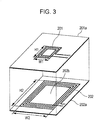
- Figs. 3 to 5 illustrate a state in which the first power transmission antenna 201 and the second power transmission antenna 202 provided in the charging device 200 are arranged.
- the first power transmission antenna 201 and the second power transmission antenna 202 are formed as a conductor pattern formed in other printed boards 201a and 202a, and the printed boards 201a and 202a are arranged in such a manner as to overlap each other inside the charging device 200.
- the power transmission antennas 201 and 202 are formed in such a manner that a conductor is wound a plurality of times in the form of a rectangle on the printed boards 201a and 202a, respectively.
- the pattern of the conductor forming the first power transmission antenna 201 is arranged in a comparatively small area in almost the center on the printed board 201a. That is, as shown in Fig. 3 , the horizontal width W1 and the vertical width H1 at the place where the pattern of the conductor as the first power transmission antenna 201 is wound are set to comparatively small sizes.
- the horizontal width W1 and the vertical width H1 of this power transmission antenna 201 are sizes that are approximately equal to the horizontal width and the vertical width of a power receiving antenna provided in the power-receiving-side apparatus.
- a horizontal width W2 and a vertical width H2 at the place where the pattern of the conductor as the second power transmission antenna 202 is wound are set to be larger than the horizontal width W1 and the vertical width H1 of the first power transmission antenna 201.
- the horizontal width W2 and the vertical width H2 are set to a size that is almost equal to the size in a case where two terminal devices 100 are arranged side by side, or to a size larger than that.
- the conductor forming the second power transmission antenna 202 is arranged on the printed board 202a in a state in which a center unit 202b is formed.
- the center unit 202b in which this conductor is not arranged has a size larger than at least the horizontal width W1 and the vertical width H1 of the first power transmission antenna 201.
- the two printed boards 201a and 202a are set to the same size.
- the printed board 201a on which the first power transmission antenna 201 is formed may be formed at a size smaller than the printed board 202a.
- the first power transmission antenna 201 is arranged above the second power transmission antenna 202.
- the second power transmission antenna 202 may be arranged above the first power transmission antenna 201.
- both the first power transmission antenna 201 and the second power transmission antenna 202 may be arranged on one printed board.
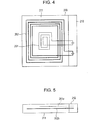
- Fig. 4 is an illustration of the arrangement of the first power transmission antenna 201 and the second power transmission antenna 202 when viewed from the top surface of the charging device 200.
- Fig. 4 illustrates an antenna arrangement inside the device, and in practice, the power transmission antennas 201 and 202 cannot be seen from the surface of the charging device 200.
- the first power transmission antenna 201 is arranged in the inner portion of the center of the planar part 211 of the charging device 200, and the second power transmission antenna 202 is arranged in the surroundings of the first power transmission antenna 201.
- the conductors forming the power transmission antennas 201 and 202 are connected to a circuit substrate (not shown) arranged in the circuit arrangement unit 212 adjacent to the planar part 211.
- Fig. 5 is an illustration of the arrangement of the power transmission antennas 201 and 202, shown in Fig. 4 , when viewed from the side surface of the charging device 200.
- the printed board 201a on which the first power transmission antenna 201 is formed, and the printed board 202a on which the second power transmission antenna 202 is formed, are arranged in such a manner as to overlap one another inside the charging device 200.
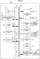
- Fig. 6 illustrates the internal configuration of a terminal device of the present embodiment.
- the terminal device 100 of the present embodiment is a mobile phone terminal device that performs wireless telephone communication, which is formed at a small size so as to be carried.
- a communication processing unit 102 to which an antenna 101 for wireless telephone communication is connected is a processing unit that performs wireless communication with a base station for wireless telephones under the control of the control unit 110.
- voice data contained in the data received by the communication processing unit 102 is supplied to an audio processing unit 103. Then, a process for decoding the voice data is performed in the audio processing unit 103, and an analog voice signal is obtained.
- the voice signal obtained by the audio processing unit 103 is supplied to a speaker 104, whereby an output is made.
- the audio signal that is picked up and obtained by a microphone 105 is supplied to the audio processing unit 103, whereby the audio signal is coded to predetermined voice data by the audio processing unit 103. Then, the obtained voice data is supplied to the communication processing unit 102, whereby the voice data is wirelessly transmitted.
- the processing units such as the communication processing unit 102 and the audio processing unit 103, perform transmission and reception of control data with the control unit 110 through a control line 121, and also perform data transmission of voice data through a data line 122. Data transmission other than this is also performed among the units inside the terminal device 100 through the control line 121 and the data line 122.
- the terminal device 100 includes a display unit 107 made up of an image display panel, a driving circuit thereof, and the like.
- the display on this display unit 107 is controlled by the control unit 110.
- Examples of displays on the display unit 107 include, in addition to a display necessary for a wireless telephone terminal device at the time of call origination and call reception, a display of electronic mail text for performing reception and transmission, a display of images obtained as a result of the connection to the Internet, and furthermore, a display as a consequence of execution of various functions provided in the terminal device 100.
- a memory 108 is connected to the control unit 110 through the control line 121 and the data line 122, with various data necessary for a communication terminal device 100 being stored in the memory 108. Furthermore, a program for performing an authentication process, which will be described later, or the like is also stored in the memory 108 when non-contact power transmission starts.
- the terminal device 100 includes a data communication processing unit 151 that performs short-distance wireless communication, and a data communication antenna 150 is connected to the data communication processing unit 151.
- the data communication processing unit 151 is a processing unit that performs wireless communication with the other party nearby
- a short distance (near field) wireless method called an NFC method
- a wireless LAN (Local Area Network) method a Bluetooth (trademark) method
- an infrared transmission method or the like can be applied.
- the short-distance wireless communication unit 151 of the terminal device 100 performs wireless communication with the charging device 200.
- the terminal device 100 includes a processing unit for performing power reception in non-contact power transmission in a magnetic-field resonance method. That is, the terminal device 100, which includes a power receiving antenna 130 that is a coil antenna, rectifies the electrical power received by the power receiving antenna 130 by using a rectifying circuit 132, and thereafter supplies the electrical power to a charging unit 140.
- the power receiving antenna 130 is arranged inside the rear surface of the configuration forming the terminal device 100.
- the power receiving antenna 130 is formed so as to be nearly the same size as the first power transmission antenna 201 of the charging device 200.
- the charging unit 140 performs a process for charging a main battery 141 that is a secondary battery.
- the power reception using the power receiving antenna 130 and the charging of the main battery 141 are performed under the control of a power-supply control unit 133.
- the power-supply control unit 133 judges the amount of received electrical power and the like, and transmits information, such as the judged amount of received electrical power, to the charging device 200 side through wireless communication using the data communication processing unit 151.
- the electrical power transmitted from the first power transmission antenna 201 of the charging device 200 or from the second power transmission antenna 202 thereof is received by the power receiving antenna 130 of the terminal device 100, and non-contact power transmission is performed.
- the state in which the power transmission antenna and the power receiving antenna are arranged is changed at the time of this non-contact power transmission, the transmission efficiency is also greatly changed.
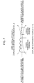
- Fig. 7 illustrates inter-antenna efficiency at the time of non-contact power transmission.
- the transmission efficiency at the time of non-contact power transmission is determined on the basis of primary side circuit efficiency (circuit efficiency on the power transmission side), the inter-antenna efficiency, and secondary side circuit efficiency (circuit efficiency on the power reception side).
- the inter-antenna efficiency is determined on the basis of the product of the coupling coefficient k of the antenna and the Q value of the resonance coil forming the antenna.
- the coupling coefficient k is a ratio of a magnetic flux ⁇ 1 that is generated by the coil forming the power transmission antenna to a magnetic flux ⁇ 2 that links the coil forming the power receiving antenna, and is represented by the following expression.
- coupling coefficient k ⁇ ⁇ 2 / ⁇ ⁇ 1 where k is a value greater than 0 and less than 1.
- the state in which the coupling coefficient is high is a case in which the shape of the power transmission antenna is the same as that of the power receiving antenna, and both the antennas have been aligned.
- the coupling coefficient is changed on the basis of the positional relationship between the power transmission antenna and the power receiving antenna.
- the power transmission antenna has a size at which a plurality of terminal devices can be mounted.
- the efficiency of non-contact power transmission is decreased to less than in the case where power transmission is performed to only one terminal device.
- control unit 207 of the charging device 200 intermittently transmits a terminal device detection signal from a data communication antenna 150 by using a data communication processing unit 209 (step S11). Then, the control unit 207 judges whether or not a response signal for the intermittently transmitted terminal device detection signal is detected (step S12), and waits until a response signal is detected.
- step S12 When it is determined in step S12 that a response signal is detected, a process for authenticating a terminal identification number (ID) for non-contact charging is performed with the terminal device 100 from which the response signal has been transmitted (step S13). This authentication process is also performed through wireless communication using the data communication processing unit 209. During this authentication process, the remaining charging level of the main battery 141 on the terminal device 100 side may be obtained by the charging device 200, and it may be determined whether or not charging to the terminal device 100 is necessary
- control unit 207 determines whether the authentication process has been completed (that is, non-contact charging is possible) or the authentication process has failed (that is, non-contact charging is not possible) (step S14).
- step S15 determines whether or not the number of terminal devices 100 in which the authentication process has been performed is one (step S15).
- the second power transmission antenna 202 is selected as a power transmission antenna by the switch 205, and electrical power transmission is started (step S21).
- the control unit 207 causes the switch 205 to select the second power transmission antenna 202 as a power transmission antenna, and performs electrical power transmission for a short time period. While the electrical power transmission is being performed, the received electrical power is measured by a power-supply control unit 133 of the terminal device 100, and the data of the measured received electrical power value is transmitted to the charging device 200 in the data transmission process using the data communication processing unit 151. In the charging device 200, a process for receiving the data of the received electrical power value transmitted by the data communication processing unit 209 is performed, and the transmission efficiency is detected on the basis of the ratio of the transmitted electrical power value to the actually received electrical power value (step S16). The transmission efficiency that is detected in this step S16 will be referred to as transmission efficiency A.
- the control unit 207 causes the switch 205 to select the first antenna 201 as a power transmission antenna, and performs electrical power transmission for a short time period. Then, while the electrical power transmission is being performed, the received electrical power is measured by the power-supply control unit 133 of the terminal device 100, and the data of the measured received electrical power value is transmitted to the charging device 200 in the data transmission process using the data communication processing unit 151.
- a process for receiving the data of the received electrical power value transmitted by the data communication processing unit 209 is performed, and the transmission efficiency is detected on the basis of the ratio of the transmission electrical power value to the actually received electrical power value (step S17). The transmission efficiency that is detected in this step S17 will be referred to as transmission efficiency B.
- the transmission efficiency A is compared with the transmission efficiency B (step S18).
- the control unit 207 causes the switch 205 to select the second power transmission antenna 202, and starts electrical power transmission for battery charging (step S19).
- the case in which the transmission efficiency A is higher than the transmission efficiency B corresponds to a state in which the position of the first power transmission antenna 201 does not match the position of the power receiving antenna 130.
- the control unit 207 selects the first power transmission antenna 201 by using the switch 205, and starts electrical power transmission for battery charging (step S20).
- the case in which the transmission efficiency B is higher than the transmission efficiency A corresponds to a state in which the position of the first power transmission antenna 201 almost matches the position of the power receiving antenna 130.
- the control unit 207 of the charging device 200 monitors the increase/decrease in the number of terminal devices 100 (step S22).
- the monitoring of this increase/decrease is performed, for example, in such a way that the intermittent transmission of a terminal device detection signal is performed in the same manner as at the time of the process in step S11 so as to monitor the presence or absence of a response from a new terminal device and also to monitor whether or not the response from the terminal device 100 in which the electrical power transmission is being performed is continued.
- step S23 it is determined whether or not all the terminal devices 100 have separated from the charging device 200.
- the control unit 207 stops the power transmission from the charging device 200 (step S24). Then, after the power transmission is stopped, the control unit 207 returns to the determination process in step S11.
- step S23 when it is determined in step S23 that the terminal device 100 exists in the vicinity of the charging device 200, the control unit 207 determines whether or not the number of terminal devices 100 has increased/decreased (step S25). When it is determined in step S25 that there is an increase/decrease in the number of terminal devices, the process returns to the determination process of step S15.
- step S25 When it is determined in step S25 that there is no increase/decrease, the control unit 207 checks whether the charging to the main battery 141 inside the terminal device 100 is to be continued (step S26), and determines whether or not the charging for all the terminal device 100s has been completed (step S27). When it is determined in step S27 that the charging for all the terminal devices 100 has not been completed (that is, there is a terminal device in which charging is being continued), the process returns to the determination process of this.
- step S27 When it is determined in step S27 that the charging for all the terminal devices 100 has been completed, the control unit 207 stops the power transmission (step S28), and detects the remaining level of the main battery 141 inside the terminal device 100 (step S29). After the detection in step S29 is performed, it is determined whether or not the detected remaining level of the battery has decreased to the remaining level of the battery at which recharging is started (step S30). When it is determined in step S30 that there is no terminal device 100 whose remaining level of the battery has reached the remaining level of the battery at which the recharging is started, the process returns to the determination of step S29.
- step S30 When it is determined in step S30 that even one terminal device 100 that has reached the remaining level of the battery at which recharging is started is detected, the process returns to the determination process of step S15.
- step S14 when it is determined in step S14 that an authentication process with a nearby terminal device has failed, error handling in which power transmission to the corresponding terminal device is not performed is performed (step S31).
- step S32 a process for detecting whether or not the terminal device in which the error handling has been performed continues to exist nearby is performed (step S32). Then, on the basis of the detection process in step S32, it is determined whether or not the corresponding terminal device has separated from the charging device 200 (step S33). When the terminal device has not separated from the charging device 200, the existence detection of step S32 is continued. When it is determined in step S33 that the corresponding terminal device has separated from the charging device 200, the process returns to the process of step S11.
- non-contact transmission is performed from the charging device 200 to the terminal device 100, and the main battery 141 inside the terminal device 100 is charged. Consequently, it is possible to satisfactorily perform non-contact power transmission from the charging device 200 to the terminal device 100. That is, for example, as shown in Fig. 1 , in a case where the terminal device 100 is mounted in nearly the center of the planar part 211 of the charging device 200, the power receiving antenna 130 on the terminal device 100 side almost matches the position of the first power transmission antenna 201, and comparatively high transmission efficiency is obtained. In the case of the arranged state shown in Fig. 1 , at the time of determination in step S18 of the flowchart of Fig. 8 , it is determined that the efficiency B is higher, and the first power transmission antenna 201 is used for power transmission.
- FIG. 9 An example of the arrangement shown in Fig. 9 is a case in which one terminal device 100 is arranged offset greatly from the center at which the first power transmission antenna 201 is arranged.
- the power receiving antenna 130 of the terminal device 100 comes into proximity to the conductor forming the second power transmission antenna 202, and the case in which the second power transmission antenna 202 is used causes the transmission efficiency to become higher. Therefore, in the case of this example of Fig. 9 , it is determined in step S18 of the flowchart of Fig. 8 that the efficiency A is higher, and the second power transmission antenna 202 is used for power transmission.
- the example of the arrangement shown in Fig. 10 is an example of a case in which one terminal device 100 is arranged at a position that is slightly offset from the center at which the first power transmission antenna 201 is arranged.
- the case of this example of Fig. 10 is a state in which a portion of the first power transmission antenna 201 overlaps a portion of the power receiving antenna 130, and there is a high probability that the first power transmission antenna 201 is used for power transmission.
- the transmission efficiency becomes slightly poorer than in the example of Fig. 1 .
- the example of the arrangement shown in Fig. 11 is a case in which two terminal devices 100 are prepared, and are arranged side by side on the planar part 211 of the charging device 200.
- the second power transmission antenna 202 that is a large antenna is used to perform power transmission, and electrical power transmission can be performed comparatively satisfactorily to two terminal devices 100.
- "NO" is set in the determination process of step S15 in the flowchart of Fig. 8 . Consequently, the second power transmission antenna 202 is always used as indicated in step S21. For this reason, a certain level of transmission efficiency is obtained.
- the second embodiment is such that the shape of the charging device and the arrangement of the power transmission antenna have been changed compared to the first embodiment.
- the configuration shown in Fig. 2 can be applied, and thus, the description thereof is omitted herein.
- a charging device 300 shown in Figs. 12 and 13 will be described.
- the charging device 300 is configured in such a manner that a housing having a first planar part 311 and a housing having a second planar part 312 are rotatably joined using a hinge unit 303.
- the first planar part 311 is arranged in such a manner as to be slightly inclined.
- a first power transmission antenna 301 is arranged in the inside of nearly the center of the first planar part 311, and a second power transmission antenna 302 is arranged in the second planar part 312.
- the first power transmission antenna 301 is an antenna of nearly the same size as the power receiving antenna 130 provided in the terminal device 100
- the second power transmission antenna 302 is an antenna in a shape larger than that of the terminal device 100.
- the antennas 301 and 302 are indicated using dashed lines
- the state in which the antennas 301 and 302 are arranged inside the housing is indicated using a solid line.
- one terminal device 100 can be mounted on the first planar part 311 side. Furthermore, one or more terminal devices 100 can be mounted on the second planar part 312 side.
- the third embodiment is such that the shape of the charging device and the arrangement of the power transmission antenna are changed when compared to the first embodiment.
- the block configuration inside the charging device is the same as the configuration shown in Fig. 2 , and thus, the description thereof is omitted herein.
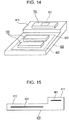
- a charging device 400 shown in Figs. 14 and 15 will be described.
- the charging device 400 is configured in such a way that a first planar part 411 and a second planar part 412 are arranged with a step difference there between.
- the first planar part 411 is arranged at a position slightly higher than that of the second planar part 412.
- a first power transmission antenna 401 is arranged in the inside of nearly the center of the first planar part 411, and a second power transmission antenna 402 is arranged in the second planar part 412.
- the first power transmission antenna 401 is an antenna of nearly the same size as the power receiving antenna 130 provided in the terminal device 100
- the second power transmission antenna 402 is an antenna in a shape larger than that of the terminal device 100.
- the antennas 401 and 402 are indicated using dashed lines
- the position of the arrangement of each of the antennas 401 and 402 inside the housing is indicated using a solid line.
- one terminal device 100 can be mounted on the first planar part 411 side, and one or more terminal devices 100 can be mounted on the second planar part 312 side.
- the fourth embodiment is also such that the shape of the charging device and the arrangement of the power transmission antenna are changed when compared to the first embodiment.
- the block configuration inside the charging device is the same as the configuration shown in Fig. 2 , and thus, the description thereof is omitted herein.
- a charging device 500 shown in Figs. 16 and 17 will be described.
- the charging device 500 is configured in such a way that a pocket part 511 and a planar part 512 are arranged side by side.
- the pocket part 511 is configured in such a way that, for example, an openable/closable lid is provided, and one terminal device 100 can be housed in the inside.
- the first power transmission antenna 501 is arranged in the inside of nearly the center of the pocket part 511, and the second power transmission antenna 502 is arranged in the planar part 512.
- the first power transmission antenna 501 is an antenna of nearly the same size as the power receiving antenna 130 provided in the terminal device 100
- the second power transmission antenna 502 is an antenna in a shape larger than that of the terminal device 100.
- the antennas 501 and 502 are indicated using dashed lines
- the positions of the antennas 501 and 502 inside the housing are indicated using solid lines.
- one or more terminal devices 100 can be mounted on the planar part 512.
- the electrical powers to be transmitted when power transmission is performed from both the power transmission antennas may be set to be the same.
- the electrical power to be transmitted may be set to be larger than that when the first power transmission antenna is used to transmit electrical power.
- transmission efficiencies based on the two antennas are compared, and the higher of the transmission efficiencies is selected.
- the received electrical powers themselves may be compared, and the larger of the received electrical powers may be selected.
- a power receiving device for receiving electrical power from the charging device a mobile phone terminal device is used.
- other power receiving devices can be used when electrical power is supplied thereto in a non-contact manner.
- Examples of a usable apparatus for which electrical power supply is necessary for the purpose of charging include a music reproduction device, a video game device, a remote control device, and a personal computer device.
- the power receiving device is used in non-contact power transmission employing a magnetic-field resonance method.
- the power receiving device can be used in non-contact power transmission based on another method as long as the method is a method of transmitting electrical power in a non-contact manner by using an antenna (coil).
Landscapes
- Engineering & Computer Science (AREA)
- Computer Networks & Wireless Communication (AREA)
- Power Engineering (AREA)
- Charge And Discharge Circuits For Batteries Or The Like (AREA)
- Transmitters (AREA)
Abstract
Description
- The present application claims the benefit of the earlier filing date of
U.S. Provisional Patent Application Serial No. 61/449,203 filed on March 4,2011 - The present disclosure relates to a non-contact power transmission apparatus. This apparatus preferably supplies electrical power to a secondary battery in an electronic apparatus.
- In recent years, a power source has been provided that can charge a secondary battery in a terminal device in a non-contact state in which a terminal of another device, such as a charging device, that supplies power, or the like is not connected to the terminal device.
- As a non-contact power transmission method that has hitherto been performed, an electromagnetic induction method is known. This is such that a power transmission coil is arranged in an apparatus on the side in which electrical power is transmitted, and a power receiving coil is arranged on the power-receiving-side terminal device. In this electromagnetic induction method, the power transmission coil of the power-transmission-side apparatus is brought into proximity of the power receiving coil of a power-receiving-side apparatus, both the coils are flux-coupled, and electrical power is supplied in a non-contact manner.
- This electromagnetic induction method is a non-contact power transmission technology that has hitherto been known. The transmissible distance is approximately several mm, and electrical power can be transmitted only among devices that are very near. For this reason, currently, the electromagnetic induction method is used in some devices, such as water-proof terminal devices in which it is difficult to expose a charging terminal.
- In comparison, in recent years, as a method for efficiently supplying electrical power in a non-contact manner to a terminal device at a long distance to a certain degree, a method called a magnetic-field resonance method has begun to be developed and put into the market. This is such that an LC circuit formed of a coil, a capacitor, and the like is provided in each of a power-transmission-side apparatus and a power-receiving-side apparatus, and magnetic fields are made to resonate between both the circuits, thereby transmitting electrical power in a wireless manner. In order to cause the magnetic fields to resonate between both the circuits, it is necessary to make the frequencies at which the resonance is performed equal to each other.
- In the case of the magnetic-field resonance method, transmission at a short distance of approximately several cm to several m becomes possible. Furthermore, if there are a plurality of power-receiving-side apparatuses within the transmissible range, electrical power transmission can be performed simultaneously from one power-transmission-side apparatus to the plurality of power-receiving-side apparatuses.
- A technology is described in Japanese Patent Application Publication No.
2010-183812 - As described above, in a case where a plurality of secondary side coils are arranged in one row in a horizontal direction, it is possible to deal with a position displacement of the power-receiving-side apparatus with respect to the direction in which the secondary side coils are arranged. However, in a case where the position is displaced in a direction different from the direction in which the secondary side coils are arranged, it is not possible to increase transmission efficiency even if any of the coils is used. Furthermore, if a large number of secondary side coils are to be arranged, the configuration of the power-transmission-side apparatus becomes complex as the number of coils arranged increases.
- In addition, in the case of the magnetic-field resonance method, electrical power can be transmitted from a primary side coil to a plurality of power-receiving-side apparatuses. However, if a large primary side coil is arranged, which can efficiently transmit electrical power to a plurality af power-receiving-side apparatuses at the same time, efficiency is not good much when electrical power is transmitted to only one power-receiving-side apparatus by the one large primary side coil.
- The inventors of the present application have recognized necessity of performing efficient electrical power transmission with a simple configuration in a case where non-contact power transmission is to be performed from a charging device to a terminal device.
- According to a first exemplary embodiment, the disclosure is directed to a non-contact power transmission apparatus that includes a power supply circuit that generates electrical power; a switch connected to an output of the power supply circuit; a first power transmission antenna connected to a first output of the switch; a second power transmission antenna connected to a second output of the switch; a communication interface that communicates with a device; and a control unit that controls the switch based on a state of the device obtained via the communication interface.
- According to another exemplary embodiment, the disclosure is directed to a method performed by a non-contact power transmission apparatus. The method includes generating, by a power supply circuit, electrical power to be provided to one of a first power transmission antenna and a second power transmission antenna, which are each connected to an output of the power supply circuit via a switch; communicating, via a communication interface, with a device; and controlling, by a control unit, the switch based on a state of the device obtained from the device via the communicating.
- According to another exemplary embodiment, the disclosure is directed to a computer-readable medium including computer program instructions, which when executed by a non-contact power transmission apparatus, cause the non-contact power transmission apparatus to perform a method comprising: controlling a switch, which is connected between a power supply circuit that generates power and first and second power transmission antennas, based on a state of a device received via a communication interface of the non-contact power transmission apparatus.
- Various respective aspects and features of the invention are defined in the appended claims. Combinations of features from the dependent claims may be combined with features of the independent claims as appropriate and not merely as explicitly set out in the claims.
- Embodiments of the invention will now be described with reference to the accompanying drawings, throughout which like parts are referred to by like references, and in which:
-
Fig. 1 is a perspective view illustrating a non-contact power transmission apparatus according to a first embodiment of the present disclosure. -
Fig. 2 is a block diagram illustrating the configuration of a charging device according to the first embodiment of the present disclosure. -
Fig. 3 is an exploded perspective view illustrating an antenna arranged state according to the first embodiment of the present disclosure. -
Fig. 4 is a plan view illustrating an antenna arranged state according to the first embodiment of the present disclosure. -
Fig. 5 is a side view illustrating an antenna arranged state according to the first embodiment of the present disclosure. -
Fig. 6 is a block diagram illustrating the configuration of a power-receiving-side terminal device according to the first embodiment of the present disclosure. -
Fig. 7 is an illustration illustrating transmission efficiency according to the first embodiment of the present disclosure. -
Fig. 8 is a flowchart illustrating the flow of a power transmission process according to the first embodiment of the present disclosure. -
Fig. 9 is an illustration illustrating an example in which a terminal device is arranged according to the first embodiment of the present disclosure. -
Fig. 10 is an illustration illustrating an example in which a terminal device is arranged according to the first embodiment of the present disclosure. -
Fig. 11 is an illustration illustrating an example in which a terminal device is arranged according to the first embodiment of the present disclosure. -
Fig. 12 is a perspective view illustrating a charging device according to a second embodiment of the present disclosure. -
Fig. 13 is a side view illustrating the charging device according to the second embodiment of the present disclosure. -
Fig. 14 is a perspective view illustrating a charging device according to a third embodiment of the present disclosure. -
Fig. 15 is a side view illustrating the charging device according to the third embodiment of the present disclosure. -
Fig. 16 is a perspective view illustrating a charging device according to a fourth embodiment of the present disclosure. -
Fig. 17 is a side view illustrating the charging device according to the fourth embodiment of the present disclosure. - Hereinafter, embodiments of the present disclosure will be described in the following order.
- 1. First Embodiment
- 1.1 Example of shapes of charging device and terminal device (
Fig. 1 ) - 1.2 Example of configuration of charging device (
Fig. 2 ) - 1.3 Antenna arrangement of charging device (
Fig. 3 to Fig. 5 ) - 1.4 Example of configuration of terminal device (
Fig. 6 ) - 1.5 Transmission efficiency at the time of power transmission (
Fig. 7 ) - 1.6 Flow of power transmission process (
Fig. 8 ) - 1.7 Example of arrangement of terminal device (
Fig. 9 to Fig. 11 ) - 2. Second Embodiment (
Fig. 12, Fig. 13 ) - 3. Third Embodiment (
Fig. 14, Fig. 15 ) - 4. Fourth Embodiment (
Fig. 16, Fig. 17 ) - 5. Modifications
- A first embodiment of the present disclosure will be described with reference to
Figs. 1 to 11 . The present embodiment is a system that is constituted by a charging device that is a non-contact power transmission apparatus and a terminal device in which an incorporated battery is charged by electrical power that is transmitted from the charging device. Electrical power transmission from the charging device to the terminal device is performed in a non-contact manner by using a magnetic-field resonance method. Furthermore, in the present embodiment, the terminal device is used as a mobile phone terminal device. -
Fig. 1 illustrates an example of the shapes of a charging device and a terminal device of the first embodiment. - A charging
device 200 is made up of a housing having aplanar part 211 on the top surface thereof. As shown inFig. 1 , as a result of mounting aterminal device 100 on theplanar part 211 of thecharging device 200, electrical power that is transmitted from a firstpower transmission antenna 201 or a secondpower transmission antenna 202 arranged inside theplanar part 211 is supplied to theterminal device 100, causing the battery inside theterminal device 100 to be charged. The example ofFig. 1 shows that only oneterminal device 100 is mounted on theplanar part 211. However, as will be described later, it is possible that a plurality of terminal devices are mounted on theplanar part 211, and these are charged at the same time. - Referring to
Fig. 2 , the configuration of a charging device of the present embodiment will be described. - The charging
device 200 includes a high-frequency power-supply circuit 206 serving as a power-supply unit. A DC power supply in which a commercial AC power supply is rectified, or a DC power supply from a car battery, is supplied to the high-frequency power-supply circuit 206. Inside the high-frequency power-supply circuit 206, a high-frequency power supply at a frequency corresponding to the resonance frequency for non-contact electrical power transmission is generated from the supplied DC power supply. Then, information on the electrical power of the high-frequency power supply that is generated by the high-frequency power-supply circuit 206, or the like, is supplied to acontrol unit 207. - Furthermore, the high-frequency power-
supply circuit 206 supplies the generated high-frequency power supply to only one of the firstpower transmission antenna 201 and the secondpower transmission antenna 202 through aswitch 205. The examples of the arrangement of the firstpower transmission antenna 201 and the secondpower transmission antenna 202 will be described later. Therespective antennas - A
matching circuit 203 is provided between theswitch 205 and the firstpower transmission antenna 201, and amatching circuit 204 is provided between theswitch 205 and the secondpower transmission antenna 202. Each of the matchingcircuits - The selection of the antenna by the switching in the
switch 205 is controlled by thecontrol unit 207. Thecontrol unit 207 performs a process for selecting an antenna in accordance with a predetermined processing procedure. The details of the processing procedure for selecting an antenna in thecontrol unit 207 will be described later. - Furthermore, the charging
device 200 includes a datacommunication processing unit 209 for performing wireless communication with adjacent terminal devices, and adata communication antenna 208 is connected to the datacommunication processing unit 209. - The data
communication processing unit 209 is a communication processing circuit acting as a short-distance wireless communication unit for performing wireless communication with terminal devices in proximity to thecharging device 200. For this datacommunication processing unit 209, for example, a short-distance wireless method (near-field wireless method) called NFC (Near Field Communication) that is applied to wireless tags is used, and a data communication process with the other party in proximity (to a degree of approximately several cm) is performed. Alternatively, for the datacommunication processing unit 209, a wireless LAN (Local Area Network) method, a Bluetooth (trademark) method, an infrared transmission method, or the like may be applied. - It is sufficient that the data
communication processing unit 209 has a capability of performing wireless communication with a terminal device that is close to such a degree as to be in contact with the chargingdevice 200, and it is not necessary for the datacommunication processing unit 209 to perform wireless communication with a terminal device that is separated to such a degree as to not be able to perform non-contact power transmission. - Data communication by the data
communication processing unit 209 is performed under the control of thecontrol unit 207. Since data communication is performed by the datacommunication processing unit 209, thecontrol unit 207 detects that a terminal device capable of receiving electrical power exists in the vicinity of thecharging device 200. Furthermore, when power transmission is to be started under the control of thecontrol unit 207, thecontrol unit 207 causes the datacommunication processing unit 209 to perform data communication so as to perform an authentication process for a power-receiving-side terminal device, and also obtains information on the power receiving state from the terminal device. -
Figs. 3 to 5 illustrate a state in which the firstpower transmission antenna 201 and the secondpower transmission antenna 202 provided in thecharging device 200 are arranged. - As shown in
Fig. 3 , the firstpower transmission antenna 201 and the secondpower transmission antenna 202 are formed as a conductor pattern formed in other printedboards boards device 200. - The
power transmission antennas boards power transmission antenna 201 is arranged in a comparatively small area in almost the center on the printedboard 201a. That is, as shown inFig. 3 , the horizontal width W1 and the vertical width H1 at the place where the pattern of the conductor as the firstpower transmission antenna 201 is wound are set to comparatively small sizes. The horizontal width W1 and the vertical width H1 of thispower transmission antenna 201 are sizes that are approximately equal to the horizontal width and the vertical width of a power receiving antenna provided in the power-receiving-side apparatus. - In contrast, a horizontal width W2 and a vertical width H2 at the place where the pattern of the conductor as the second
power transmission antenna 202 is wound are set to be larger than the horizontal width W1 and the vertical width H1 of the firstpower transmission antenna 201. For example, the horizontal width W2 and the vertical width H2 are set to a size that is almost equal to the size in a case where twoterminal devices 100 are arranged side by side, or to a size larger than that. Furthermore, the conductor forming the secondpower transmission antenna 202 is arranged on the printedboard 202a in a state in which acenter unit 202b is formed. Thecenter unit 202b in which this conductor is not arranged has a size larger than at least the horizontal width W1 and the vertical width H1 of the firstpower transmission antenna 201. - In
Fig. 3 , the two printedboards board 201a on which the firstpower transmission antenna 201 is formed may be formed at a size smaller than the printedboard 202a. Furthermore, in the example ofFig. 3 , the firstpower transmission antenna 201 is arranged above the secondpower transmission antenna 202. Conversely, the secondpower transmission antenna 202 may be arranged above the firstpower transmission antenna 201. In addition, as a configuration in which a multilayered conductor is arranged on one printed board, both the firstpower transmission antenna 201 and the secondpower transmission antenna 202 may be arranged on one printed board. -
Fig. 4 is an illustration of the arrangement of the firstpower transmission antenna 201 and the secondpower transmission antenna 202 when viewed from the top surface of thecharging device 200.Fig. 4 illustrates an antenna arrangement inside the device, and in practice, thepower transmission antennas charging device 200. - As shown in
Fig. 4 , the firstpower transmission antenna 201 is arranged in the inner portion of the center of theplanar part 211 of thecharging device 200, and the secondpower transmission antenna 202 is arranged in the surroundings of the firstpower transmission antenna 201. The conductors forming thepower transmission antennas circuit arrangement unit 212 adjacent to theplanar part 211. -
Fig. 5 is an illustration of the arrangement of thepower transmission antennas Fig. 4 , when viewed from the side surface of thecharging device 200. - As shown in
Fig. 5 , the printedboard 201a on which the firstpower transmission antenna 201 is formed, and the printedboard 202a on which the secondpower transmission antenna 202 is formed, are arranged in such a manner as to overlap one another inside the chargingdevice 200. -
Fig. 6 illustrates the internal configuration of a terminal device of the present embodiment. Theterminal device 100 of the present embodiment is a mobile phone terminal device that performs wireless telephone communication, which is formed at a small size so as to be carried. - Referring to
Fig. 6 , the configuration of the terminal device 100 (seeFig. 1 ) will be described. Acommunication processing unit 102 to which anantenna 101 for wireless telephone communication is connected is a processing unit that performs wireless communication with a base station for wireless telephones under the control of thecontrol unit 110. - At the time of a voice call, voice data contained in the data received by the
communication processing unit 102 is supplied to anaudio processing unit 103. Then, a process for decoding the voice data is performed in theaudio processing unit 103, and an analog voice signal is obtained. The voice signal obtained by theaudio processing unit 103 is supplied to aspeaker 104, whereby an output is made. - Furthermore, the audio signal that is picked up and obtained by a
microphone 105 is supplied to theaudio processing unit 103, whereby the audio signal is coded to predetermined voice data by theaudio processing unit 103. Then, the obtained voice data is supplied to thecommunication processing unit 102, whereby the voice data is wirelessly transmitted. - The processing units, such as the
communication processing unit 102 and theaudio processing unit 103, perform transmission and reception of control data with thecontrol unit 110 through acontrol line 121, and also perform data transmission of voice data through adata line 122. Data transmission other than this is also performed among the units inside theterminal device 100 through thecontrol line 121 and thedata line 122. - Operation data from the
operation unit 106 made up of keys, a touch panel, and the like, theoperation unit 106 being operated by a user, is supplied to the control unit 120, and a process indicated by the operation data is performed by thecontrol unit 110. - Furthermore, the
terminal device 100 includes adisplay unit 107 made up of an image display panel, a driving circuit thereof, and the like. The display on thisdisplay unit 107 is controlled by thecontrol unit 110. Examples of displays on thedisplay unit 107 include, in addition to a display necessary for a wireless telephone terminal device at the time of call origination and call reception, a display of electronic mail text for performing reception and transmission, a display of images obtained as a result of the connection to the Internet, and furthermore, a display as a consequence of execution of various functions provided in theterminal device 100. - A
memory 108 is connected to thecontrol unit 110 through thecontrol line 121 and thedata line 122, with various data necessary for acommunication terminal device 100 being stored in thememory 108. Furthermore, a program for performing an authentication process, which will be described later, or the like is also stored in thememory 108 when non-contact power transmission starts. - Furthermore, the
terminal device 100 includes a datacommunication processing unit 151 that performs short-distance wireless communication, and adata communication antenna 150 is connected to the datacommunication processing unit 151. The datacommunication processing unit 151 is a processing unit that performs wireless communication with the other party nearby For short-distance wireless communication, for example, a short distance (near field) wireless method called an NFC method, a wireless LAN (Local Area Network) method, a Bluetooth (trademark) method, an infrared transmission method, or the like can be applied. - In the present embodiment, when the
terminal device 100 performs power reception from the chargingdevice 200, the short-distancewireless communication unit 151 of theterminal device 100 performs wireless communication with the chargingdevice 200. - Furthermore, the
terminal device 100 includes a processing unit for performing power reception in non-contact power transmission in a magnetic-field resonance method. That is, theterminal device 100, which includes apower receiving antenna 130 that is a coil antenna, rectifies the electrical power received by thepower receiving antenna 130 by using arectifying circuit 132, and thereafter supplies the electrical power to acharging unit 140. Thepower receiving antenna 130 is arranged inside the rear surface of the configuration forming theterminal device 100. Thepower receiving antenna 130 is formed so as to be nearly the same size as the firstpower transmission antenna 201 of thecharging device 200. By using the electrical power obtained from the rectifyingcircuit 132, the chargingunit 140 performs a process for charging amain battery 141 that is a secondary battery. - The power reception using the
power receiving antenna 130 and the charging of themain battery 141 are performed under the control of a power-supply control unit 133. - When the control of the power reception is to be performed by the power-
supply control unit 133, the power-supply control unit 133 judges the amount of received electrical power and the like, and transmits information, such as the judged amount of received electrical power, to thecharging device 200 side through wireless communication using the datacommunication processing unit 151. - As a result of mounting the
terminal device 100 on theplanar part 211 of thecharging device 200 as shown inFig. 1 , the electrical power transmitted from the firstpower transmission antenna 201 of thecharging device 200 or from the secondpower transmission antenna 202 thereof is received by thepower receiving antenna 130 of theterminal device 100, and non-contact power transmission is performed. When the state in which the power transmission antenna and the power receiving antenna are arranged is changed at the time of this non-contact power transmission, the transmission efficiency is also greatly changed. -
Fig. 7 illustrates inter-antenna efficiency at the time of non-contact power transmission. The transmission efficiency at the time of non-contact power transmission is determined on the basis of primary side circuit efficiency (circuit efficiency on the power transmission side), the inter-antenna efficiency, and secondary side circuit efficiency (circuit efficiency on the power reception side). - The inter-antenna efficiency is determined on the basis of the product of the coupling coefficient k of the antenna and the Q value of the resonance coil forming the antenna.
- The coupling coefficient k is a ratio of a magnetic flux φ1 that is generated by the coil forming the power transmission antenna to a magnetic flux φ2 that links the coil forming the power receiving antenna, and is represented by the following expression.

where k is a value greater than 0 and less than 1. - As can be seen from the expression of the above-mentioned coupling coefficient, the state in which the coupling coefficient is high is a case in which the shape of the power transmission antenna is the same as that of the power receiving antenna, and both the antennas have been aligned. The coupling coefficient is changed on the basis of the positional relationship between the power transmission antenna and the power receiving antenna. On the other hand, in a case where power transmission is to be performed from one charging device to a plurality of terminal devices at the same time, it is preferable that the power transmission antenna has a size at which a plurality of terminal devices can be mounted. However, even if the power transmission antenna is made large, since the coupling coefficient is resultingly decreased, the efficiency of non-contact power transmission is decreased to less than in the case where power transmission is performed to only one terminal device.
- Next, a description will be given, with reference to the flowchart of
Fig. 8 , of an example of a processing procedure in which non-contact power transmission is performed from the chargingdevice 200 to theterminal device 100 so as to charge themain battery 141 inside theterminal device 100. The process of this flowchart ofFig. 8 is performed under the control of thecontrol unit 207 of thecharging device 200. - First, the
control unit 207 of thecharging device 200 intermittently transmits a terminal device detection signal from adata communication antenna 150 by using a data communication processing unit 209 (step S11). Then, thecontrol unit 207 judges whether or not a response signal for the intermittently transmitted terminal device detection signal is detected (step S12), and waits until a response signal is detected. - When it is determined in step S12 that a response signal is detected, a process for authenticating a terminal identification number (ID) for non-contact charging is performed with the
terminal device 100 from which the response signal has been transmitted (step S13). This authentication process is also performed through wireless communication using the datacommunication processing unit 209. During this authentication process, the remaining charging level of themain battery 141 on theterminal device 100 side may be obtained by the chargingdevice 200, and it may be determined whether or not charging to theterminal device 100 is necessary - After that, on the basis of the result of the authentication process in step S13, the
control unit 207 determines whether the authentication process has been completed (that is, non-contact charging is possible) or the authentication process has failed (that is, non-contact charging is not possible) (step S14). - When it is determined in step S14 that the authentication process has been completed and the
terminal device 100 capable of being charged without contact has come nearby, thecontrol unit 207 determines whether or not the number ofterminal devices 100 in which the authentication process has been performed is one (step S15). When it is determined in step S15 that the number ofterminal devices 100 is not one (that is, plural), the secondpower transmission antenna 202 is selected as a power transmission antenna by theswitch 205, and electrical power transmission is started (step S21). - When it is determined in step S15 that the number of
terminal devices 100 is one, thecontrol unit 207 causes theswitch 205 to select the secondpower transmission antenna 202 as a power transmission antenna, and performs electrical power transmission for a short time period. While the electrical power transmission is being performed, the received electrical power is measured by a power-supply control unit 133 of theterminal device 100, and the data of the measured received electrical power value is transmitted to thecharging device 200 in the data transmission process using the datacommunication processing unit 151. In thecharging device 200, a process for receiving the data of the received electrical power value transmitted by the datacommunication processing unit 209 is performed, and the transmission efficiency is detected on the basis of the ratio of the transmitted electrical power value to the actually received electrical power value (step S16). The transmission efficiency that is detected in this step S16 will be referred to as transmission efficiency A. - After that, the
control unit 207 causes theswitch 205 to select thefirst antenna 201 as a power transmission antenna, and performs electrical power transmission for a short time period. Then, while the electrical power transmission is being performed, the received electrical power is measured by the power-supply control unit 133 of theterminal device 100, and the data of the measured received electrical power value is transmitted to thecharging device 200 in the data transmission process using the datacommunication processing unit 151. In thecharging device 200, a process for receiving the data of the received electrical power value transmitted by the datacommunication processing unit 209 is performed, and the transmission efficiency is detected on the basis of the ratio of the transmission electrical power value to the actually received electrical power value (step S17). The transmission efficiency that is detected in this step S17 will be referred to as transmission efficiency B. - When the transmission efficiencies A and B are obtained, in the
control unit 207, the transmission efficiency A is compared with the transmission efficiency B (step S18). When the transmission efficiency A is determined to be higher at the comparison in step S18, thecontrol unit 207 causes theswitch 205 to select the secondpower transmission antenna 202, and starts electrical power transmission for battery charging (step S19). The case in which the transmission efficiency A is higher than the transmission efficiency B corresponds to a state in which the position of the firstpower transmission antenna 201 does not match the position of thepower receiving antenna 130. - When it is determined in the comparison of step S18 that the transmission efficiency B is higher, the
control unit 207 selects the firstpower transmission antenna 201 by using theswitch 205, and starts electrical power transmission for battery charging (step S20). The case in which the transmission efficiency B is higher than the transmission efficiency A corresponds to a state in which the position of the firstpower transmission antenna 201 almost matches the position of thepower receiving antenna 130. - When the electrical power transmission in steps S19, S20, and S21 starts, the
control unit 207 of thecharging device 200 monitors the increase/decrease in the number of terminal devices 100 (step S22). The monitoring of this increase/decrease is performed, for example, in such a way that the intermittent transmission of a terminal device detection signal is performed in the same manner as at the time of the process in step S11 so as to monitor the presence or absence of a response from a new terminal device and also to monitor whether or not the response from theterminal device 100 in which the electrical power transmission is being performed is continued. - Then, on the basis of the monitoring result in step S22, it is determined whether or not all the
terminal devices 100 have separated from the charging device 200 (step S23). When it is determined in step S23 that all theterminal devices 100 have separated from the chargingdevice 200, thecontrol unit 207 stops the power transmission from the charging device 200 (step S24). Then, after the power transmission is stopped, thecontrol unit 207 returns to the determination process in step S11. - Also, when it is determined in step S23 that the
terminal device 100 exists in the vicinity of thecharging device 200, thecontrol unit 207 determines whether or not the number ofterminal devices 100 has increased/decreased (step S25). When it is determined in step S25 that there is an increase/decrease in the number of terminal devices, the process returns to the determination process of step S15. - When it is determined in step S25 that there is no increase/decrease, the
control unit 207 checks whether the charging to themain battery 141 inside theterminal device 100 is to be continued (step S26), and determines whether or not the charging for all the terminal device 100s has been completed (step S27). When it is determined in step S27 that the charging for all theterminal devices 100 has not been completed (that is, there is a terminal device in which charging is being continued), the process returns to the determination process of this. - When it is determined in step S27 that the charging for all the
terminal devices 100 has been completed, thecontrol unit 207 stops the power transmission (step S28), and detects the remaining level of themain battery 141 inside the terminal device 100 (step S29). After the detection in step S29 is performed, it is determined whether or not the detected remaining level of the battery has decreased to the remaining level of the battery at which recharging is started (step S30). When it is determined in step S30 that there is noterminal device 100 whose remaining level of the battery has reached the remaining level of the battery at which the recharging is started, the process returns to the determination of step S29. - When it is determined in step S30 that even one
terminal device 100 that has reached the remaining level of the battery at which recharging is started is detected, the process returns to the determination process of step S15. - Furthermore, when it is determined in step S14 that an authentication process with a nearby terminal device has failed, error handling in which power transmission to the corresponding terminal device is not performed is performed (step S31). In addition, a process for detecting whether or not the terminal device in which the error handling has been performed continues to exist nearby is performed (step S32). Then, on the basis of the detection process in step S32, it is determined whether or not the corresponding terminal device has separated from the charging device 200 (step S33). When the terminal device has not separated from the charging
device 200, the existence detection of step S32 is continued. When it is determined in step S33 that the corresponding terminal device has separated from the chargingdevice 200, the process returns to the process of step S11. - With such a processing procedure, non-contact transmission is performed from the charging
device 200 to theterminal device 100, and themain battery 141 inside theterminal device 100 is charged. Consequently, it is possible to satisfactorily perform non-contact power transmission from the chargingdevice 200 to theterminal device 100. That is, for example, as shown inFig. 1 , in a case where theterminal device 100 is mounted in nearly the center of theplanar part 211 of thecharging device 200, thepower receiving antenna 130 on theterminal device 100 side almost matches the position of the firstpower transmission antenna 201, and comparatively high transmission efficiency is obtained. In the case of the arranged state shown inFig. 1 , at the time of determination in step S18 of the flowchart ofFig. 8 , it is determined that the efficiency B is higher, and the firstpower transmission antenna 201 is used for power transmission. - Next, examples of states in which terminal devices are arranged, which differ from the state in which the terminal device of
Fig. 1 is arranged, will be described with reference toFigs. 9 to 11 . - An example of the arrangement shown in
Fig. 9 is a case in which oneterminal device 100 is arranged offset greatly from the center at which the firstpower transmission antenna 201 is arranged. - In the case of this example of
Fig. 9 , thepower receiving antenna 130 of theterminal device 100 comes into proximity to the conductor forming the secondpower transmission antenna 202, and the case in which the secondpower transmission antenna 202 is used causes the transmission efficiency to become higher. Therefore, in the case of this example ofFig. 9 , it is determined in step S18 of the flowchart ofFig. 8 that the efficiency A is higher, and the secondpower transmission antenna 202 is used for power transmission. - In the case of this example of
Fig. 9 , the transmission efficiency becomes poorer than in the example ofFig. 1 . However, since the largepower transmission antenna 202 is used to perform a power transmission process, non-contact power transmission is more satisfactory than in a case in which the smallpower transmission antenna 201 is used and electrical power transmission is performed. - The example of the arrangement shown in
Fig. 10 is an example of a case in which oneterminal device 100 is arranged at a position that is slightly offset from the center at which the firstpower transmission antenna 201 is arranged. - The case of this example of
Fig. 10 is a state in which a portion of the firstpower transmission antenna 201 overlaps a portion of thepower receiving antenna 130, and there is a high probability that the firstpower transmission antenna 201 is used for power transmission. However, in the case of the arranged state of this example ofFig. 10 , the transmission efficiency becomes slightly poorer than in the example ofFig. 1 . - The example of the arrangement shown in
Fig. 11 is a case in which twoterminal devices 100 are prepared, and are arranged side by side on theplanar part 211 of thecharging device 200. - In this case, regardless of the positional relationship between the
terminal devices 100, the secondpower transmission antenna 202 that is a large antenna is used to perform power transmission, and electrical power transmission can be performed comparatively satisfactorily to twoterminal devices 100. As described above, in the case where twoterminal devices 100 are mounted, "NO" is set in the determination process of step S15 in the flowchart ofFig. 8 . Consequently, the secondpower transmission antenna 202 is always used as indicated in step S21. For this reason, a certain level of transmission efficiency is obtained. - Next, a second embodiment of the present disclosure will be described with reference to
Figs. 12 and 13 . - The second embodiment is such that the shape of the charging device and the arrangement of the power transmission antenna have been changed compared to the first embodiment. For the block configuration inside the charging device, the configuration shown in
Fig. 2 can be applied, and thus, the description thereof is omitted herein. - A charging
device 300 shown inFigs. 12 and 13 will be described. The chargingdevice 300 is configured in such a manner that a housing having a firstplanar part 311 and a housing having a secondplanar part 312 are rotatably joined using ahinge unit 303. In the example ofFigs. 12 and 13 , the firstplanar part 311 is arranged in such a manner as to be slightly inclined. - Then, a first
power transmission antenna 301 is arranged in the inside of nearly the center of the firstplanar part 311, and a secondpower transmission antenna 302 is arranged in the secondplanar part 312. The firstpower transmission antenna 301 is an antenna of nearly the same size as thepower receiving antenna 130 provided in theterminal device 100, and the secondpower transmission antenna 302 is an antenna in a shape larger than that of theterminal device 100. In the perspective view ofFig. 12 , theantennas Fig. 13 , the state in which theantennas - As shown in
Fig. 12 , oneterminal device 100 can be mounted on the firstplanar part 311 side. Furthermore, one or moreterminal devices 100 can be mounted on the secondplanar part 312 side. - Also, in the case of the configurations shown in
Figs. 12 and 13 , for example, by using a process for selecting a power transmission antenna, which is indicated in the flowchart ofFig. 8 , selection of an appropriate power transmission antenna can be made, and advantageous effects that are the same as those in the case of the first embodiment are obtained. - Next, a third embodiment of the present disclosure will be described with reference to
Figs. 14 and 15 . - The third embodiment is such that the shape of the charging device and the arrangement of the power transmission antenna are changed when compared to the first embodiment. The block configuration inside the charging device is the same as the configuration shown in
Fig. 2 , and thus, the description thereof is omitted herein. - A charging
device 400 shown inFigs. 14 and 15 will be described. The chargingdevice 400 is configured in such a way that a firstplanar part 411 and a secondplanar part 412 are arranged with a step difference there between. In the examples ofFigs. 14 and 15 , the firstplanar part 411 is arranged at a position slightly higher than that of the secondplanar part 412. - Then, a first
power transmission antenna 401 is arranged in the inside of nearly the center of the firstplanar part 411, and a secondpower transmission antenna 402 is arranged in the secondplanar part 412. The firstpower transmission antenna 401 is an antenna of nearly the same size as thepower receiving antenna 130 provided in theterminal device 100, and the secondpower transmission antenna 402 is an antenna in a shape larger than that of theterminal device 100. In the perspective view ofFig. 14 , theantennas Fig. 15 , the position of the arrangement of each of theantennas - As shown in
Fig. 14 , oneterminal device 100 can be mounted on the firstplanar part 411 side, and one or moreterminal devices 100 can be mounted on the secondplanar part 312 side. - Also, in the configurations shown in
Figs. 14 and 15 , for example, by using a process for selecting a power transmission antenna, which is shown in the flowchart ofFig. 8 , it is possible to select an appropriate power transmission antenna, and advantageous effects that are same as those in the case of the first embodiment are obtained. - Next, a fourth embodiment of the present disclosure will be described with reference to
Figs. 16 and 17 . The fourth embodiment is also such that the shape of the charging device and the arrangement of the power transmission antenna are changed when compared to the first embodiment. The block configuration inside the charging device is the same as the configuration shown inFig. 2 , and thus, the description thereof is omitted herein. - A charging
device 500 shown inFigs. 16 and 17 will be described. The chargingdevice 500 is configured in such a way that apocket part 511 and aplanar part 512 are arranged side by side. Thepocket part 511 is configured in such a way that, for example, an openable/closable lid is provided, and oneterminal device 100 can be housed in the inside. - Then, the first
power transmission antenna 501 is arranged in the inside of nearly the center of thepocket part 511, and the secondpower transmission antenna 502 is arranged in theplanar part 512. The firstpower transmission antenna 501 is an antenna of nearly the same size as thepower receiving antenna 130 provided in theterminal device 100, and the secondpower transmission antenna 502 is an antenna in a shape larger than that of theterminal device 100. In the perspective view ofFig. 16 , theantennas Fig. 17 , the positions of theantennas - As shown in
Fig. 16 , one or moreterminal devices 100 can be mounted on theplanar part 512. - Also, in the case of the configurations shown in
Figs. 16 and 17 , for example, a process for selecting a power transmission antenna, which is shown inFig. 8 , is applied. Consequently, it is possible to select an appropriate power transmission antenna, and advantageous effects that are the same as those of the first embodiment are obtained. - In each of the above-mentioned embodiments, no particular description has been given regarding the setting in a charging device when power transmission is performed from the first power transmission antenna that is a comparatively small antenna and when power transmission is performed from the second power transmission antenna that is a comparatively large antenna. The electrical powers to be transmitted when power transmission is performed from both the power transmission antennas may be set to be the same. For example, in a case where the second power transmission antenna is used to transmit electrical power, the electrical power to be transmitted may be set to be larger than that when the first power transmission antenna is used to transmit electrical power.
- Furthermore, at the time of the determination process in step S18 of the flowchart of
Fig. 8 , transmission efficiencies based on the two antennas are compared, and the higher of the transmission efficiencies is selected. Alternatively, the received electrical powers themselves may be compared, and the larger of the received electrical powers may be selected. - Furthermore, in the above-mentioned embodiments, as a power receiving device for receiving electrical power from the charging device, a mobile phone terminal device is used. Needless to say, other power receiving devices can be used when electrical power is supplied thereto in a non-contact manner. Examples of a usable apparatus for which electrical power supply is necessary for the purpose of charging include a music reproduction device, a video game device, a remote control device, and a personal computer device.
- Furthermore, in the above-described embodiments, the power receiving device is used in non-contact power transmission employing a magnetic-field resonance method. However, the power receiving device can be used in non-contact power transmission based on another method as long as the method is a method of transmitting electrical power in a non-contact manner by using an antenna (coil).
- Furthermore, the configurations and the processes described in the claims of the present disclosure are not limited to the above-described embodiments. It should be understood, of course, by those skilled in the art that various modifications, combinations, and other embodiments may be made according to the design or other elements insofar as they come within the scope of the claims.
- In so far as the embodiments of the invention described above are implemented, at least in part, using software-controlled data processing apparatus, it will be appreciated that a computer program providing such software control and a transmission, storage or other medium by which such a computer program is provided are envisaged as aspects of the present invention.
- Advantageous features, embodiments and/or aspects of the invention can be generally defined using the following numbered paragraphs.
- 1. A non-contact power transmission apparatus, comprising:
- a power supply circuit that generates electrical power;
- a switch connected to an output of the power supply circuit;
- a first power transmission antenna connected to a first output of the switch;
- a second power transmission antenna connected to a second output of the switch;
- a communication interface that communicates with a device; and
- a control unit that controls the switch based on a state of the device obtained via the communication interface, the non-contact power transmission apparatus of
claim 1, further comprising:- a first matching circuit connected between the first output of the switch and the first power transmission antenna; and
- a second matching circuit connected between the second output of the switch and the second power transmission antenna, the non-contact power transmission apparatus of
claim 1, wherein - the second power transmission antenna is larger than the first power transmission antenna, the non-contact power transmission apparatus of claim 3, further comprising:
- a first printed board on which the first power transmission antenna is formed; and
- a second printed board on which the second power transmission antenna is formed.
- 2. The non-contact power transmission apparatus of
paragraph 1, wherein
the first printed board is disposed to overlap the second planar printed board. - 3. The non-contact power transmission apparatus of
paragraph 2, further comprising:- a hinge unit that rotatably joins the first printed board and the second printed board.
- 4. The non-contact power transmission apparatus of
paragraph 2, wherein
the first and second printed boards are arranged such that a first plane defined by the first printed board and a second plane defined by the second printed board are parallel. - 5. The non-contact power transmission apparatus of paragraph 4, wherein
the first and second printed boards do not overlap one another when viewed in a direction perpendicular to the first and second planes. - 6. The non-contact power transmission apparatus of paragraph 4, further comprising:
- a lid portion that detachably covers the first printed board.
Claims (15)
- A non-contact power transmission apparatus, comprising:a power supply circuit that generates electrical power;a switch connected to an output of the power supply circuit;a first power transmission antenna connected to a first output of the switch;a second power transmission antenna connected to a second output of the switch;a communication interface that communicates with a device; anda control unit that controls the switch based on a state of the device obtained via the communication interface.
- The non-contact power transmission apparatus of claim 1, further comprising:a first matching circuit connected between the first output of the switch and the first power transmission antenna; anda second matching circuit connected between the second output of the switch and the second power transmission antenna.
- The non-contact power transmission apparatus of claim 1, wherein
the second power transmission antenna is larger than the first power transmission antenna. - The non-contact power transmission apparatus of claim 3, further comprising:a first printed board on which the first power transmission antenna is formed; anda second printed board on which the second power transmission antenna is formed.
- The non-contact power transmission apparatus of claim 4, wherein the first printed board is disposed to overlap the second planar printed board and
a first area defined by a periphery of the second power transmission antenna formed on the second printed board is greater than, and encompasses, a second area defined by a periphery of the first power transmission antenna formed on the first printed board. - The non-contact power transmission apparatus of claim 1, wherein
the control unit detects whether the device is located in proximity to the non-contact power transmission apparatus based on a signal received from the device via the communication interface. - The non-contact power transmission apparatus of claim 6, wherein
when the device is detected in proximity to the non-contact power transmission apparatus, the control unit controls the switch so that power is transmitted from the second power transmission antenna for a first predetermined period of time. - The non-contact power transmission apparatus of claim 7, wherein
the control unit determines a first transmission efficiency metric corresponding to the power transmitted from the second power transmission antenna to the device based on first data received from the device. - The non-contact power transmission apparatus of claim 8, wherein
when the first predetermine period of time lapses, the control unit controls the switch so that power is transmitted from the first power transmission antenna for a second predetermined period of time. - The non-contact power transmission apparatus of claim 9, wherein
the control unit determines a second transmission efficiency metric corresponding to the power transmitted from the first power transmission antenna to the device based on second data received from the device. - The non-contact power transmission apparatus of claim 10, wherein
when the second predetermined period of time lapses, the control unit compares the first and second power transmission efficiency metrics, and controls the switch based on a result of the comparison. - The non-contact power transmission apparatus of claim 1, wherein
the control unit detects whether a plurality of devices are located in proximity to the non-contact power transmission apparatus based on a signal received from the plurality of devices via the communication interface. - The non-contact power transmission apparatus of claim 12, wherein
the control unit controls the switch based a result of the detection. - A method performed by a non-contact power transmission apparatus, the method comprising:generating, by a power supply circuit, electrical power to be provided to one of a first power transmission antenna and a second power transmission antenna, which are each connected to an output of the power supply circuit via a switch;communicating, via a communication interface, with a device; andcontrolling, by a control unit, the switch based on a state of the device obtained from the device via the communicating.
- A computer-readable medium including computer program instructions, which when executed by a non-contact power transmission apparatus, cause the non-contact power transmission apparatus to perform a method comprising:controlling a switch, which is connected between a power supply circuit that generates power and first and second power transmission antennas, based on a state of a device received via a communication interface of the non-contact power transmission apparatus.
Applications Claiming Priority (2)
| Application Number | Priority Date | Filing Date | Title |
|---|---|---|---|
| US201161449203P | 2011-03-04 | 2011-03-04 | |
| US13/349,966 US8941268B2 (en) | 2011-03-04 | 2012-01-13 | Non-contact power transmission apparatus |
Publications (3)
| Publication Number | Publication Date |
|---|---|
| EP2495842A2 true EP2495842A2 (en) | 2012-09-05 |
| EP2495842A3 EP2495842A3 (en) | 2015-01-21 |
| EP2495842B1 EP2495842B1 (en) | 2019-08-14 |
Family
ID=45655468
Family Applications (1)
| Application Number | Title | Priority Date | Filing Date |
|---|---|---|---|
| EP12154553.7A Active EP2495842B1 (en) | 2011-03-04 | 2012-02-08 | Non-contact power transmission apparatus |
Country Status (2)
| Country | Link |
|---|---|
| US (1) | US8941268B2 (en) |
| EP (1) | EP2495842B1 (en) |
Cited By (1)
| Publication number | Priority date | Publication date | Assignee | Title |
|---|---|---|---|---|
| WO2014163874A3 (en) * | 2013-03-12 | 2015-06-11 | Qualcomm Incorporated | Systems and methods for extending the power capability of a wireless charger |
Families Citing this family (17)
| Publication number | Priority date | Publication date | Assignee | Title |
|---|---|---|---|---|
| KR101813131B1 (en) * | 2011-05-11 | 2017-12-28 | 삼성전자주식회사 | Wireless power transmission system and method for controlling of resonance frequency and resonance impedance of wireless power transmission system |
| JP5790200B2 (en) * | 2011-06-27 | 2015-10-07 | ソニー株式会社 | Communication apparatus and communication system |
| US9507447B2 (en) * | 2011-12-08 | 2016-11-29 | Atmel Corporation | Touch sensor with inductive charging |
| JP5211256B1 (en) * | 2011-12-22 | 2013-06-12 | Necトーキン株式会社 | Electronic equipment and system |
| US9160180B2 (en) | 2011-12-29 | 2015-10-13 | Sony Corporation | Charging apparatus for charging a secondary battery with a wireless feeding method |
| WO2013114576A1 (en) * | 2012-01-31 | 2013-08-08 | 富士通株式会社 | Power transmission device, power transmission system, and power transmission method |
| KR20150054836A (en) * | 2012-11-15 | 2015-05-20 | 쥬코쿠 덴료쿠 가부시키 가이샤 | Non-contact power supply system and control method for non-contact power supply system |
| JP6126373B2 (en) * | 2012-12-13 | 2017-05-10 | パナソニック株式会社 | Wireless module and wireless communication device |
| JP6207152B2 (en) | 2012-12-27 | 2017-10-04 | キヤノン株式会社 | Power supply apparatus, control method, and computer program |
| JP6214238B2 (en) * | 2013-06-28 | 2017-10-18 | オリンパス株式会社 | Imaging device |
| JP2015019022A (en) * | 2013-07-12 | 2015-01-29 | 東芝テック株式会社 | Power transmission device and coil device |
| JP6348734B2 (en) * | 2014-03-06 | 2018-06-27 | パナソニック インテレクチュアル プロパティ コーポレーション オブ アメリカPanasonic Intellectual Property Corporation of America | Proximity wireless communication device |
| JP2016067076A (en) | 2014-09-22 | 2016-04-28 | キヤノン株式会社 | Power supply device, control method, and program |
| US9960607B2 (en) * | 2014-12-29 | 2018-05-01 | Qualcomm Incorporated | Systems, methods and apparatus for reducing intra-base array network coupling |
| US9837864B2 (en) * | 2015-03-26 | 2017-12-05 | Integrated Device Technology, Inc. | Apparatuses and wireless power transmitters having multiple transmit coils and related method |
| JP2018153026A (en) * | 2017-03-14 | 2018-09-27 | オムロンオートモーティブエレクトロニクス株式会社 | Transmission apparatus |
| JP6757452B2 (en) * | 2019-08-27 | 2020-09-16 | キヤノン株式会社 | Transmission equipment, control methods, and programs |
Citations (1)
| Publication number | Priority date | Publication date | Assignee | Title |
|---|---|---|---|---|
| JP2010183812A (en) | 2009-02-09 | 2010-08-19 | Toyota Industries Corp | Resonance type non-contact charging system |
Family Cites Families (11)
| Publication number | Priority date | Publication date | Assignee | Title |
|---|---|---|---|---|
| DE20110585U1 (en) * | 2001-06-11 | 2001-11-15 | Cubit Electronics GmbH, 99099 Erfurt | Contactless transponder |
| JP4089778B2 (en) * | 2002-11-07 | 2008-05-28 | 株式会社アイデンビデオトロニクス | Energy supply equipment |
| US7844306B2 (en) * | 2005-05-24 | 2010-11-30 | Powercast Corporation | Power transmission network |
| JP4155408B2 (en) | 2005-09-29 | 2008-09-24 | ソニー・エリクソン・モバイルコミュニケーションズ株式会社 | Charging device and charging system |
| US8169185B2 (en) * | 2006-01-31 | 2012-05-01 | Mojo Mobility, Inc. | System and method for inductive charging of portable devices |
| CN102106054A (en) * | 2007-03-22 | 2011-06-22 | 鲍尔马特有限公司 | Signal transfer system |
| JP5106237B2 (en) * | 2008-05-02 | 2012-12-26 | オリンパス株式会社 | Wireless power supply system |
| US8629650B2 (en) * | 2008-05-13 | 2014-01-14 | Qualcomm Incorporated | Wireless power transfer using multiple transmit antennas |
| EP2357716B1 (en) * | 2008-12-12 | 2017-08-30 | Intel Corporation | Contactless power transmission device |
| US8853890B2 (en) | 2010-07-09 | 2014-10-07 | Sony Corporation | Power supply device, communication terminal device, and non-contact power transmission method |
| US8853889B2 (en) | 2010-09-08 | 2014-10-07 | Sony Corporation | Communication terminal apparatus and method for supplying terminal power source |
-
2012
- 2012-01-13 US US13/349,966 patent/US8941268B2/en active Active
- 2012-02-08 EP EP12154553.7A patent/EP2495842B1/en active Active
Patent Citations (1)
| Publication number | Priority date | Publication date | Assignee | Title |
|---|---|---|---|---|
| JP2010183812A (en) | 2009-02-09 | 2010-08-19 | Toyota Industries Corp | Resonance type non-contact charging system |
Cited By (1)
| Publication number | Priority date | Publication date | Assignee | Title |
|---|---|---|---|---|
| WO2014163874A3 (en) * | 2013-03-12 | 2015-06-11 | Qualcomm Incorporated | Systems and methods for extending the power capability of a wireless charger |
Also Published As
| Publication number | Publication date |
|---|---|
| EP2495842B1 (en) | 2019-08-14 |
| EP2495842A3 (en) | 2015-01-21 |
| US20120223588A1 (en) | 2012-09-06 |
| US8941268B2 (en) | 2015-01-27 |
Similar Documents
| Publication | Publication Date | Title |
|---|---|---|
| EP2495842B1 (en) | Non-contact power transmission apparatus | |
| US9024576B2 (en) | Inductive charging of a rechargeable battery | |
| JP5622612B2 (en) | Portable electronic devices | |
| US9893424B2 (en) | Flexible printed circuit board for dual mode antennas, dual mode antenna and user device | |
| EP3065304B1 (en) | Mobile terminal and coil antenna modul | |
| EP2406864B1 (en) | Wireless power transfer for chargeable devices | |
| EP3066673B1 (en) | Arrangement of a communication coil and an induction charging coil | |
| CN103907265B (en) | Power reception device, power transmission device, and wireless power transmission system | |
| US9124303B2 (en) | Apparatus and method for near field communication | |
| CN102780515A (en) | Method and apparatus for achieving compatibility of wireless charging and near field communication (NFC) | |
| JP2010284065A (en) | Power/signal transmission module, noncontact charging module, and noncontact charging and signal transmission systems | |
| KR20140091362A (en) | Wireless charge battery modul for common installing NFC antena and recive coil on battery | |
| JP5855968B2 (en) | Mobile communication terminal, communication terminal system, and method for controlling charging by a non-contact charger | |
| US20140011446A1 (en) | Communications Connection | |
| KR20060048692A (en) | Communication system, communication terminal device and wireless key device | |
| EP3291407B1 (en) | Wireless power reception apparatus | |
| JP4742841B2 (en) | Wireless communication device | |
| WO2017064968A1 (en) | Power reception device, electronic apparatus, and power supply system | |
| JP2006020002A (en) | Communication system, communication terminal, wireless key apparatus and program | |
| CN112886994A (en) | Terminal | |
| US20250079907A1 (en) | Wireless Power Transfer Relay | |
| JP5529697B2 (en) | Non-contact charging device and non-contact charging system | |
| US10523051B2 (en) | Power feeding unit, power receiving unit, and feed system | |
| KR20180124274A (en) | Wireless charge patch apparatus and wireless charge receiver for both magnetic induction and magnetic resonance | |
| JP2000151252A (en) | Wireless communication device |
Legal Events
| Date | Code | Title | Description |
|---|---|---|---|
| PUAI | Public reference made under article 153(3) epc to a published international application that has entered the european phase |
Free format text: ORIGINAL CODE: 0009012 |
|
| 17P | Request for examination filed |
Effective date: 20120227 |
|
| AK | Designated contracting states |
Kind code of ref document: A2 Designated state(s): AL AT BE BG CH CY CZ DE DK EE ES FI FR GB GR HR HU IE IS IT LI LT LU LV MC MK MT NL NO PL PT RO RS SE SI SK SM TR |
|
| AX | Request for extension of the european patent |
Extension state: BA ME |
|
| PUAL | Search report despatched |
Free format text: ORIGINAL CODE: 0009013 |
|
| AK | Designated contracting states |
Kind code of ref document: A3 Designated state(s): AL AT BE BG CH CY CZ DE DK EE ES FI FR GB GR HR HU IE IS IT LI LT LU LV MC MK MT NL NO PL PT RO RS SE SI SK SM TR |
|
| AX | Request for extension of the european patent |
Extension state: BA ME |
|
| RIC1 | Information provided on ipc code assigned before grant |
Ipc: H02J 5/00 20060101AFI20141218BHEP Ipc: H02J 17/00 20060101ALI20141218BHEP Ipc: H02J 7/02 20060101ALI20141218BHEP Ipc: H01F 38/14 20060101ALI20141218BHEP |
|
| 17Q | First examination report despatched |
Effective date: 20151207 |
|
| STAA | Information on the status of an ep patent application or granted ep patent |
Free format text: STATUS: EXAMINATION IS IN PROGRESS |
|
| GRAP | Despatch of communication of intention to grant a patent |
Free format text: ORIGINAL CODE: EPIDOSNIGR1 |
|
| STAA | Information on the status of an ep patent application or granted ep patent |
Free format text: STATUS: GRANT OF PATENT IS INTENDED |
|
| RIC1 | Information provided on ipc code assigned before grant |
Ipc: H01F 38/14 20060101ALI20190220BHEP Ipc: H02J 5/00 20160101AFI20190220BHEP |
|
| INTG | Intention to grant announced |
Effective date: 20190318 |
|
| RAP1 | Party data changed (applicant data changed or rights of an application transferred) |
Owner name: SONY CORPORATION |
|
| GRAS | Grant fee paid |
Free format text: ORIGINAL CODE: EPIDOSNIGR3 |
|
| GRAA | (expected) grant |
Free format text: ORIGINAL CODE: 0009210 |
|
| STAA | Information on the status of an ep patent application or granted ep patent |
Free format text: STATUS: THE PATENT HAS BEEN GRANTED |
|
| AK | Designated contracting states |
Kind code of ref document: B1 Designated state(s): AL AT BE BG CH CY CZ DE DK EE ES FI FR GB GR HR HU IE IS IT LI LT LU LV MC MK MT NL NO PL PT RO RS SE SI SK SM TR |
|
| REG | Reference to a national code |
Ref country code: GB Ref legal event code: FG4D |
|
| REG | Reference to a national code |
Ref country code: CH Ref legal event code: EP Ref country code: AT Ref legal event code: REF Ref document number: 1168157 Country of ref document: AT Kind code of ref document: T Effective date: 20190815 |
|
| REG | Reference to a national code |
Ref country code: DE Ref legal event code: R096 Ref document number: 602012062881 Country of ref document: DE |
|
| REG | Reference to a national code |
Ref country code: IE Ref legal event code: FG4D |
|
| REG | Reference to a national code |
Ref country code: NL Ref legal event code: FP |
|
| REG | Reference to a national code |
Ref country code: LT Ref legal event code: MG4D |
|
| PG25 | Lapsed in a contracting state [announced via postgrant information from national office to epo] |
Ref country code: FI Free format text: LAPSE BECAUSE OF FAILURE TO SUBMIT A TRANSLATION OF THE DESCRIPTION OR TO PAY THE FEE WITHIN THE PRESCRIBED TIME-LIMIT Effective date: 20190814 Ref country code: LT Free format text: LAPSE BECAUSE OF FAILURE TO SUBMIT A TRANSLATION OF THE DESCRIPTION OR TO PAY THE FEE WITHIN THE PRESCRIBED TIME-LIMIT Effective date: 20190814 Ref country code: PT Free format text: LAPSE BECAUSE OF FAILURE TO SUBMIT A TRANSLATION OF THE DESCRIPTION OR TO PAY THE FEE WITHIN THE PRESCRIBED TIME-LIMIT Effective date: 20191216 Ref country code: HR Free format text: LAPSE BECAUSE OF FAILURE TO SUBMIT A TRANSLATION OF THE DESCRIPTION OR TO PAY THE FEE WITHIN THE PRESCRIBED TIME-LIMIT Effective date: 20190814 Ref country code: BG Free format text: LAPSE BECAUSE OF FAILURE TO SUBMIT A TRANSLATION OF THE DESCRIPTION OR TO PAY THE FEE WITHIN THE PRESCRIBED TIME-LIMIT Effective date: 20191114 Ref country code: NO Free format text: LAPSE BECAUSE OF FAILURE TO SUBMIT A TRANSLATION OF THE DESCRIPTION OR TO PAY THE FEE WITHIN THE PRESCRIBED TIME-LIMIT Effective date: 20191114 Ref country code: SE Free format text: LAPSE BECAUSE OF FAILURE TO SUBMIT A TRANSLATION OF THE DESCRIPTION OR TO PAY THE FEE WITHIN THE PRESCRIBED TIME-LIMIT Effective date: 20190814 |
|
| REG | Reference to a national code |
Ref country code: AT Ref legal event code: MK05 Ref document number: 1168157 Country of ref document: AT Kind code of ref document: T Effective date: 20190814 |
|
| PG25 | Lapsed in a contracting state [announced via postgrant information from national office to epo] |
Ref country code: ES Free format text: LAPSE BECAUSE OF FAILURE TO SUBMIT A TRANSLATION OF THE DESCRIPTION OR TO PAY THE FEE WITHIN THE PRESCRIBED TIME-LIMIT Effective date: 20190814 Ref country code: GR Free format text: LAPSE BECAUSE OF FAILURE TO SUBMIT A TRANSLATION OF THE DESCRIPTION OR TO PAY THE FEE WITHIN THE PRESCRIBED TIME-LIMIT Effective date: 20191115 Ref country code: AL Free format text: LAPSE BECAUSE OF FAILURE TO SUBMIT A TRANSLATION OF THE DESCRIPTION OR TO PAY THE FEE WITHIN THE PRESCRIBED TIME-LIMIT Effective date: 20190814 Ref country code: LV Free format text: LAPSE BECAUSE OF FAILURE TO SUBMIT A TRANSLATION OF THE DESCRIPTION OR TO PAY THE FEE WITHIN THE PRESCRIBED TIME-LIMIT Effective date: 20190814 Ref country code: IS Free format text: LAPSE BECAUSE OF FAILURE TO SUBMIT A TRANSLATION OF THE DESCRIPTION OR TO PAY THE FEE WITHIN THE PRESCRIBED TIME-LIMIT Effective date: 20191214 Ref country code: RS Free format text: LAPSE BECAUSE OF FAILURE TO SUBMIT A TRANSLATION OF THE DESCRIPTION OR TO PAY THE FEE WITHIN THE PRESCRIBED TIME-LIMIT Effective date: 20190814 |
|
| PG25 | Lapsed in a contracting state [announced via postgrant information from national office to epo] |
Ref country code: TR Free format text: LAPSE BECAUSE OF FAILURE TO SUBMIT A TRANSLATION OF THE DESCRIPTION OR TO PAY THE FEE WITHIN THE PRESCRIBED TIME-LIMIT Effective date: 20190814 |
|
| PG25 | Lapsed in a contracting state [announced via postgrant information from national office to epo] |
Ref country code: EE Free format text: LAPSE BECAUSE OF FAILURE TO SUBMIT A TRANSLATION OF THE DESCRIPTION OR TO PAY THE FEE WITHIN THE PRESCRIBED TIME-LIMIT Effective date: 20190814 Ref country code: IT Free format text: LAPSE BECAUSE OF FAILURE TO SUBMIT A TRANSLATION OF THE DESCRIPTION OR TO PAY THE FEE WITHIN THE PRESCRIBED TIME-LIMIT Effective date: 20190814 Ref country code: PL Free format text: LAPSE BECAUSE OF FAILURE TO SUBMIT A TRANSLATION OF THE DESCRIPTION OR TO PAY THE FEE WITHIN THE PRESCRIBED TIME-LIMIT Effective date: 20190814 Ref country code: AT Free format text: LAPSE BECAUSE OF FAILURE TO SUBMIT A TRANSLATION OF THE DESCRIPTION OR TO PAY THE FEE WITHIN THE PRESCRIBED TIME-LIMIT Effective date: 20190814 Ref country code: RO Free format text: LAPSE BECAUSE OF FAILURE TO SUBMIT A TRANSLATION OF THE DESCRIPTION OR TO PAY THE FEE WITHIN THE PRESCRIBED TIME-LIMIT Effective date: 20190814 Ref country code: DK Free format text: LAPSE BECAUSE OF FAILURE TO SUBMIT A TRANSLATION OF THE DESCRIPTION OR TO PAY THE FEE WITHIN THE PRESCRIBED TIME-LIMIT Effective date: 20190814 |
|
| PG25 | Lapsed in a contracting state [announced via postgrant information from national office to epo] |
Ref country code: SK Free format text: LAPSE BECAUSE OF FAILURE TO SUBMIT A TRANSLATION OF THE DESCRIPTION OR TO PAY THE FEE WITHIN THE PRESCRIBED TIME-LIMIT Effective date: 20190814 Ref country code: SM Free format text: LAPSE BECAUSE OF FAILURE TO SUBMIT A TRANSLATION OF THE DESCRIPTION OR TO PAY THE FEE WITHIN THE PRESCRIBED TIME-LIMIT Effective date: 20190814 Ref country code: IS Free format text: LAPSE BECAUSE OF FAILURE TO SUBMIT A TRANSLATION OF THE DESCRIPTION OR TO PAY THE FEE WITHIN THE PRESCRIBED TIME-LIMIT Effective date: 20200224 Ref country code: CZ Free format text: LAPSE BECAUSE OF FAILURE TO SUBMIT A TRANSLATION OF THE DESCRIPTION OR TO PAY THE FEE WITHIN THE PRESCRIBED TIME-LIMIT Effective date: 20190814 |
|
| REG | Reference to a national code |
Ref country code: DE Ref legal event code: R097 Ref document number: 602012062881 Country of ref document: DE |
|
| PLBE | No opposition filed within time limit |
Free format text: ORIGINAL CODE: 0009261 |
|
| STAA | Information on the status of an ep patent application or granted ep patent |
Free format text: STATUS: NO OPPOSITION FILED WITHIN TIME LIMIT |
|
| PG2D | Information on lapse in contracting state deleted |
Ref country code: IS |
|
| 26N | No opposition filed |
Effective date: 20200603 |
|
| PG25 | Lapsed in a contracting state [announced via postgrant information from national office to epo] |
Ref country code: SI Free format text: LAPSE BECAUSE OF FAILURE TO SUBMIT A TRANSLATION OF THE DESCRIPTION OR TO PAY THE FEE WITHIN THE PRESCRIBED TIME-LIMIT Effective date: 20190814 |
|
| REG | Reference to a national code |
Ref country code: CH Ref legal event code: PL |
|
| GBPC | Gb: european patent ceased through non-payment of renewal fee |
Effective date: 20200208 |
|
| REG | Reference to a national code |
Ref country code: BE Ref legal event code: MM Effective date: 20200229 |
|
| PG25 | Lapsed in a contracting state [announced via postgrant information from national office to epo] |
Ref country code: LU Free format text: LAPSE BECAUSE OF NON-PAYMENT OF DUE FEES Effective date: 20200208 Ref country code: MC Free format text: LAPSE BECAUSE OF FAILURE TO SUBMIT A TRANSLATION OF THE DESCRIPTION OR TO PAY THE FEE WITHIN THE PRESCRIBED TIME-LIMIT Effective date: 20190814 |
|
| PG25 | Lapsed in a contracting state [announced via postgrant information from national office to epo] |
Ref country code: CH Free format text: LAPSE BECAUSE OF NON-PAYMENT OF DUE FEES Effective date: 20200229 Ref country code: LI Free format text: LAPSE BECAUSE OF NON-PAYMENT OF DUE FEES Effective date: 20200229 |
|
| PG25 | Lapsed in a contracting state [announced via postgrant information from national office to epo] |
Ref country code: IE Free format text: LAPSE BECAUSE OF NON-PAYMENT OF DUE FEES Effective date: 20200208 Ref country code: GB Free format text: LAPSE BECAUSE OF NON-PAYMENT OF DUE FEES Effective date: 20200208 Ref country code: FR Free format text: LAPSE BECAUSE OF NON-PAYMENT OF DUE FEES Effective date: 20200229 |
|
| PG25 | Lapsed in a contracting state [announced via postgrant information from national office to epo] |
Ref country code: BE Free format text: LAPSE BECAUSE OF NON-PAYMENT OF DUE FEES Effective date: 20200229 |
|
| PG25 | Lapsed in a contracting state [announced via postgrant information from national office to epo] |
Ref country code: MT Free format text: LAPSE BECAUSE OF FAILURE TO SUBMIT A TRANSLATION OF THE DESCRIPTION OR TO PAY THE FEE WITHIN THE PRESCRIBED TIME-LIMIT Effective date: 20190814 Ref country code: CY Free format text: LAPSE BECAUSE OF FAILURE TO SUBMIT A TRANSLATION OF THE DESCRIPTION OR TO PAY THE FEE WITHIN THE PRESCRIBED TIME-LIMIT Effective date: 20190814 |
|
| PG25 | Lapsed in a contracting state [announced via postgrant information from national office to epo] |
Ref country code: MK Free format text: LAPSE BECAUSE OF FAILURE TO SUBMIT A TRANSLATION OF THE DESCRIPTION OR TO PAY THE FEE WITHIN THE PRESCRIBED TIME-LIMIT Effective date: 20190814 |
|
| P01 | Opt-out of the competence of the unified patent court (upc) registered |
Effective date: 20230527 |
|
| PGFP | Annual fee paid to national office [announced via postgrant information from national office to epo] |
Ref country code: NL Payment date: 20240123 Year of fee payment: 13 |
|
| REG | Reference to a national code |
Ref country code: NL Ref legal event code: MM Effective date: 20250301 |
|
| PG25 | Lapsed in a contracting state [announced via postgrant information from national office to epo] |
Ref country code: NL Free format text: LAPSE BECAUSE OF NON-PAYMENT OF DUE FEES Effective date: 20250301 |
|
| REG | Reference to a national code |
Ref country code: DE Ref legal event code: R079 Ref document number: 602012062881 Country of ref document: DE Free format text: PREVIOUS MAIN CLASS: H02J0005000000 Ipc: H02J0004250000 |
|
| PGFP | Annual fee paid to national office [announced via postgrant information from national office to epo] |
Ref country code: DE Payment date: 20260121 Year of fee payment: 15 |