EP2495503A1 - Controller and air conditioner - Google Patents
Controller and air conditioner Download PDFInfo
- Publication number
- EP2495503A1 EP2495503A1 EP10826873A EP10826873A EP2495503A1 EP 2495503 A1 EP2495503 A1 EP 2495503A1 EP 10826873 A EP10826873 A EP 10826873A EP 10826873 A EP10826873 A EP 10826873A EP 2495503 A1 EP2495503 A1 EP 2495503A1
- Authority
- EP
- European Patent Office
- Prior art keywords
- outlets
- wind direction
- flaps
- air
- main
- Prior art date
- Legal status (The legal status is an assumption and is not a legal conclusion. Google has not performed a legal analysis and makes no representation as to the accuracy of the status listed.)
- Granted
Links
Images









Classifications
-
- F—MECHANICAL ENGINEERING; LIGHTING; HEATING; WEAPONS; BLASTING
- F24—HEATING; RANGES; VENTILATING
- F24F—AIR-CONDITIONING; AIR-HUMIDIFICATION; VENTILATION; USE OF AIR CURRENTS FOR SCREENING
- F24F11/00—Control or safety arrangements
- F24F11/70—Control systems characterised by their outputs; Constructional details thereof
- F24F11/72—Control systems characterised by their outputs; Constructional details thereof for controlling the supply of treated air, e.g. its pressure
- F24F11/79—Control systems characterised by their outputs; Constructional details thereof for controlling the supply of treated air, e.g. its pressure for controlling the direction of the supplied air
-
- F—MECHANICAL ENGINEERING; LIGHTING; HEATING; WEAPONS; BLASTING
- F24—HEATING; RANGES; VENTILATING
- F24F—AIR-CONDITIONING; AIR-HUMIDIFICATION; VENTILATION; USE OF AIR CURRENTS FOR SCREENING
- F24F11/00—Control or safety arrangements
- F24F11/30—Control or safety arrangements for purposes related to the operation of the system, e.g. for safety or monitoring
-
- F—MECHANICAL ENGINEERING; LIGHTING; HEATING; WEAPONS; BLASTING
- F24—HEATING; RANGES; VENTILATING
- F24F—AIR-CONDITIONING; AIR-HUMIDIFICATION; VENTILATION; USE OF AIR CURRENTS FOR SCREENING
- F24F1/00—Room units for air-conditioning, e.g. separate or self-contained units or units receiving primary air from a central station
- F24F1/0007—Indoor units, e.g. fan coil units
- F24F1/0011—Indoor units, e.g. fan coil units characterised by air outlets
- F24F1/0014—Indoor units, e.g. fan coil units characterised by air outlets having two or more outlet openings
-
- F—MECHANICAL ENGINEERING; LIGHTING; HEATING; WEAPONS; BLASTING
- F24—HEATING; RANGES; VENTILATING
- F24F—AIR-CONDITIONING; AIR-HUMIDIFICATION; VENTILATION; USE OF AIR CURRENTS FOR SCREENING
- F24F1/00—Room units for air-conditioning, e.g. separate or self-contained units or units receiving primary air from a central station
- F24F1/0007—Indoor units, e.g. fan coil units
- F24F1/0043—Indoor units, e.g. fan coil units characterised by mounting arrangements
- F24F1/0047—Indoor units, e.g. fan coil units characterised by mounting arrangements mounted in the ceiling or at the ceiling
-
- F—MECHANICAL ENGINEERING; LIGHTING; HEATING; WEAPONS; BLASTING
- F24—HEATING; RANGES; VENTILATING
- F24F—AIR-CONDITIONING; AIR-HUMIDIFICATION; VENTILATION; USE OF AIR CURRENTS FOR SCREENING
- F24F11/00—Control or safety arrangements
- F24F11/50—Control or safety arrangements characterised by user interfaces or communication
- F24F11/52—Indication arrangements, e.g. displays
-
- F—MECHANICAL ENGINEERING; LIGHTING; HEATING; WEAPONS; BLASTING
- F24—HEATING; RANGES; VENTILATING
- F24F—AIR-CONDITIONING; AIR-HUMIDIFICATION; VENTILATION; USE OF AIR CURRENTS FOR SCREENING
- F24F13/00—Details common to, or for air-conditioning, air-humidification, ventilation or use of air currents for screening
- F24F13/02—Ducting arrangements
- F24F13/06—Outlets for directing or distributing air into rooms or spaces, e.g. ceiling air diffuser
- F24F2013/0616—Outlets that have intake openings
Definitions
- the present invention relates to a controller and an air conditioner having the same, the controller being configured to accept operations entered for the air conditioner.
- the ceiling embedded indoor unit has a plurality of outlets for the discharge of air-conditioning air.
- the outlets have flaps disposed to change the discharge direction of the air-conditioning air (see, for example, Patent Document 1).
- the operation of the flaps is controlled by a single motor.
- an air conditioner that includes the indoor unit having a plurality of flaps respectively disposed at the outlets, it is conceivable to individually control the flaps.
- the wind directions of the plurality of outlets are preferably displayed by the controller so that the user can easily confirm.
- a first aspect of the present invention is a controller for an indoor unit that includes a plurality of flaps of substantially the same shape respectively disposed at a plurality of outlets, and capable of individually changing the discharge direction of the air-conditioning air, comprising a display section that displays at least two pieces of information of selected ones of the plurality of outlets and/or selected ones of the plurality of flaps.
- a second aspect of the present invention is the controller of the first aspect, further comprising: an operation section that accepts an operation entered to control the position of the plurality of flaps, wherein the display section simultaneously displays information indicative of the discharge directions of the air-conditioning air from selected ones of the plurality of outlets.
- the user can visually conf irm on the display section the wind directions currently set for the outlets.
- a third aspect of the present invention is the controller of the first aspect, adapted so that: in the indoor unit, different sign sections are respectively provided either in the vicinity of the plurality of outlets or on the plurality of flaps; and the display section is capable of displaying information corresponding to the sign sections.
- the flap in need of, for example, wind direction change can be individually identified only by looking at the sign sections formed in the vicinity of the plurality of outlets or on the plurality of flaps. Further, with the display on the display section corresponding to the sign sections, the plurality of outlets or the plurality of flaps are easily recognized.
- a fourth aspect of the present invention is the controller of the third aspect, adapted so that the display section is capable of displaying information corresponding to the sign sections simultaneously with information indicative of the discharge directions of the air-conditioning air at the outlets indicated by the sign sections.
- a fifth aspect of the present invention is the controller of the second aspect, adapted so that the operation section enables the positions of the plurality of flaps to be individually changed so as to change the discharge direction of the air-conditioning air at the plurality of outlets.
- a sixth aspect of the present invention is the controller of the second aspect, adapted so that the operation section enables the positions of the plurality of flaps to be changed at once so as to change the discharge direction of the air-conditioning air at the plurality of outlets.
- a seventh aspect of the present invention is the controller of the sixth aspect, adapted so that the operation section enables the positions of the selected ones of the plurality of flaps to be changed at once so as to change the discharge direction of the air-conditioning air at the plurality of outlets.
- An eighth aspect of the present invention is the controller of the first aspect, connected to an air conditioner via a wire.
- controller is a wired remote control
- pieces of information of the outlets and the flaps are simultaneously displayed in a list as in the case of the wireless remote control.
- a ninth aspect of the present invention is an air conditioner comprising the controller according to any one of the first to eighth aspects.
- a tenth aspect of the present invention is the air conditioner of the ninth aspect, adapted so that, in the indoor unit, different sign sections are respectively provided either in the vicinity of the plurality of outlets or on the plurality of flaps.
- the flap in need of, for example, wind direction change can easily be identified only by looking at the sign sections formed in the vicinity of the plurality of outlets or on the plurality of flaps.
- An eleventh aspect of the present invention is the air conditioner of the tenth aspect, adapted so that the sign sections are three-dimensionally provided as raised portions or recessed portions.
- a twelfth aspect of the present invention is the air conditioner of the tenth aspect, adapted so that, in the indoor unit, the sign sections are provided by being printed or by attaching stickers.
- the sign sections can easily be formed by being printed or by attaching stickers.
- a thirteenth aspect of the present invention is the air conditioner of any one of the tenth to twelfth aspects, adapted so that the sign sections are provided as characters, figures, or combinations of characters and figures.
- the present invention has the following effects.
- pieces of information of all the outlets and/or the flaps are simultaneously listed.
- a user by looking at this list, can grasp the current settings of all the outlets and flaps at once.
- the user can visually confirm on the display section the wind directions currently set for the outlets.
- the flap in need of, for example, wind direction change can be individually identified only by looking at the sign sections formed in the vicinity of the plurality of outlets or on the plurality of flaps. Further, with the display on the display section corresponding to the sign sections, the plurality of outlets or the plurality of flaps are easily recognized.
- usability can be improved, because a user looking at the display section can simultaneously grasp the outlets and the discharge directions currently set for the outlets.
- the positions of the flaps can be individually changed.
- the position of each flap can be changed at once without accompanying individual operations for the flaps.
- the positions of only the selected flaps can be changed at once.
- controller is a wired remote control
- pieces of information of the outlets and the flaps are simultaneously displayed in a list as in the case of the wireless remote control.
- the flap in need of, for example, wind direction change can easily be identified only by looking at the sign sections formed in the vicinity of the plurality of outlets or on the plurality of flaps.
- the eleventh aspect a user can easily identify the sign sections, because the sign sections are three-dimensionally provided as raised portions or recessed portions.
- the sign sections can easily be formed by being printed or by attaching stickers.
- a user can individually identify the outlets and the flaps more reliably, because the sign sections are provided as characters, figures, or combinations of characters and figures.
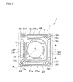
- FIG. 1 is an external perspective view of an indoor unit 1 according to First Embodiment of the present invention.
- FIG. 2 is a schematic planar cross sectional of the indoor unit 1.
- FIG. 3 is a cross sectional view taken at line A-O-A of FIG. 2 .
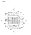
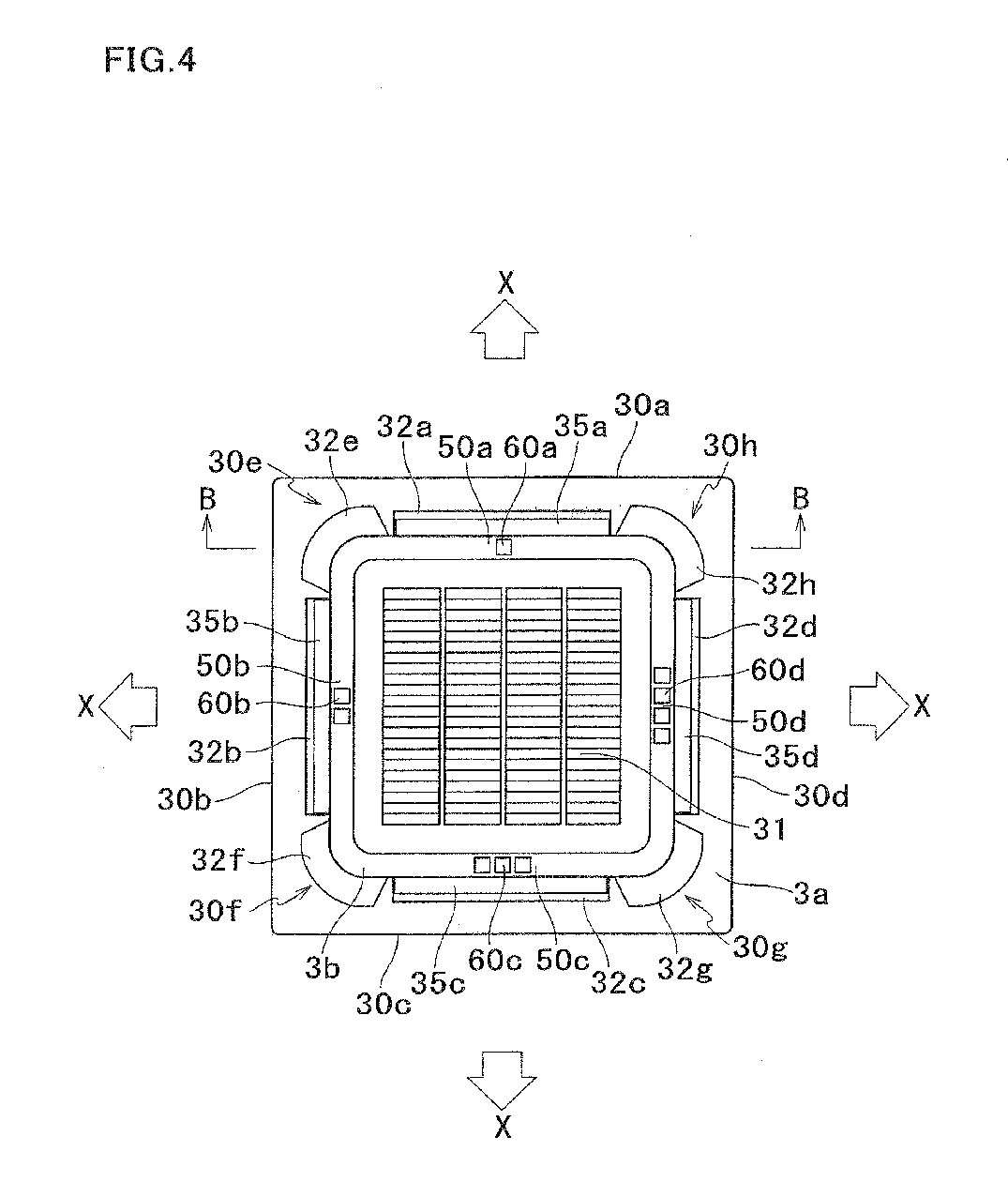
- FIG. 4 is a plan view of a decorative panel of the indoor unit 1 as viewed from an air-conditioned room.
- FIG. 5 is an enlarged view of FIG. 3 , illustrating a channel portion corresponding to a main outlet 32d.
- FIG. 6 is a cross sectional view taken at line B-B of FIG. 4 .
- the indoor unit 1 is a ceiling embedded indoor unit, and includes a casing 2 housing various constituting units therein.
- the casing 2 is configured from a casing main body 2a, and a decorative panel 3 disposed under the casing main body 2a.
- the casing main body 2a as illustrated in FIG. 3 , is disposed by being inserted into the opening formed in ceiling U of an air-conditioned room.
- the decorative panel 3 is fitted to the opening of the ceiling U.
- the indoor unit 1 can be controlled by the operation of a wired remote control 83 connected via a communication cable W (wire) laid along the ceiling surface (not illustrated).
- the casing main body 2a is box-like in shape with a substantially octagonal open bottom of alternating longer sides and shorter sides as seen in a planar view, and includes a substantially octagonal top board 21 formed by the continuous and alternating longer sides and shorter sides, and side boards 22 extending downward from the peripheries of the top board 21.
- the side boards 22 include side boards 22a to 22d corresponding the longer sides of the top board 21, and side boards 22e to 22h corresponding to the shorter sides of the top board 21.
- the side board 22a and the side board 22b are disposed substantially orthogonal to each other via the side board 22e.
- the side boards 22b and 22c, the side boards 22c and 22d, and the side boards 22d and 22a are also disposed in a substantially orthogonal fashion.
- the side board 22e is disposed at an about 135 degree angle with respect to the adjacent side boards 22a and 22b.
- the side boards 22g and 22h are also disposed at an about 135 degree angle with respect to the adjacent side boards, as with the side board 22e.
- the side board 22f has a different shape from the other side boards, because the side board 22f is where a refrigerant pipe provided for the exchange of a refrigerant between a heat exchanger 6 and an outdoor unit (not illustrated) passes through.
- the side boards 22e to 22h are each provided with a fixing bracket 23 used to install the casing main body 2a in the ceiling space. In the casing main body 2a, the lengths of the longer and shorter sides of the top board 21 are set so that the shape including the fixing brackets 23 appears substantially rectangular as seen in a planar view.
- the decorative panel 3 is a substantially rectangular plate unit as seen in a planar view, and configured from mainly a panel main body 3a fixed to the bottom portions of the casing main body 2a.
- the panel main body 3a has alternately and continuously formed four panel side portions 30a to 30d (side portions) and four panel corner portions 30e to 30h.
- the panel side portions 30a to 30d correspond to the side boards 22a to 22d, respectively, of the casing main body 2a.
- the panel corner portions 30e to 30h correspond to the side boards 22e to 22h, respectively, of the casing main body 2a.
- the panel main body 3a includes an intake 31 formed substantially at the center to draw air from the air-conditioned room, and four main outlets 32a to 32d, respectively corresponding to the panel side portions 30a to 30d, through which the air inside the casing main body 2a discharges into the air-conditioned room.
- the intake 31 is a substantially square opening.
- the four main outlets 32a to 32d have substantially the same shape, and are disposed along the panel side portions 30a to 30d, respectively.
- the panel main body 3a includes auxiliary outlets 32e to 32h, corresponding in position to the panel corner portions 30e to 30h, respectively.
- a four-sided, flat annular, panel lower surface portion 3b is provided around the intake 31 on the lower surface of the panel main body 3a by being surrounded by the four main outlets 32a to 32d.
- the panel lower surface portion 3b has rim portions 50a to 50d in the vicinity of the main outlets 32a to 32d, on the intake 31 side of the main outlets 32a to 32d.
- the intake 31 is disposed on the inner side of the main outlets 32a to 32d.
- the intake 31 includes an intake grill 33, and a filter 34 provided to remove dust in the air drawn through the intake 31.
- the main outlets 32a to 32d are provided with flaps 35a to 35d, respectively, that are swingable about an axis along the longitudinal direction.
- the flaps 35a to 35d are long, narrow substantially rectangular blade members of substantially the same shape extending along the longitudinal direction of their respective main outlets 32a to 32d.
- the flaps 35a to 35d are swingable about an axis along the longitudinal direction of the main outlets 32a to 32d by being rotatably supported on the decorative panel 3.
- sign sections 60a to 60d for individually recognizing the main outlets 32a to 32d or the flaps 35a to 35d are formed on the rim portions 50a to 50d of the panel lower surface portion 3b.
- the sign sections 60a to 60d are formed as figures “ ⁇ ", “ ⁇ ⁇ ", “ ⁇ ⁇ ⁇ ”, and “ ⁇ ”.
- the sign sections 60a to 60d are formed on the intake 31 side of the main outlets 32a to 32d.
- the figures “ ⁇ ” to “ ⁇ ” correspond to numbers “1" to "4", respectively, which, in FIG. 4 , are arranged in ascending order in the counterclockwise direction.
- the figures “ ⁇ ” to “ ⁇ ” are disposed in positions corresponding to the main outlets 32a to 32d, respectively. As illustrated in FIG.
- the sign sections 60a to 60d are three-dimensionally " ⁇ " provided as recessed portions in the rim portions 50a to 50d. Note that the areas surrounding the sign sections 60a to 60d are matte finished (surface texturing), whereas the sign sections are more glossy (gloss portions) relative to the surroundings.
- the flaps 35a to 35d can be set to the swing state that involves continuous driving by flap motors 40a to 40d (see FIG. 7 ), or the stationary state in which the discharge direction of air-conditioning air is fixed. In the swing state setting, the flaps 35a to 35d continuously swing to change the discharge direction of the air-conditioning air. On the other hand, in the stationary state setting, the flaps 35a to 35d assume the predetermined wind direction position and fix the discharge direction of the air-conditioning air in a certain direction. As illustrated in FIG. 4 , the flaps 35a to 35d can swing to individually change the wind directions of the air flow X discharged into the air-conditioned room through the main outlets 32a to 32d.
- the wind direction of the air flow X discharged into the air-conditioned room through the main outlet 32d can be varied by the flap 35d upwardly and downwardly with respect to the lower surface of the ceiling U.
- the wind direction of the air flow X can have six settings: “wind direction 1" to "wind direction 5", and “swing” in which the flaps swing over the range of "wind direction 1" to "wind direction 5".
- the wind directions are set so that the wind is sloped more downwardly with increasing numbers from “wind direction 1" to "wind direction 5".
- the wind directions of the air flow X discharged into the air-conditioned room through the other main outlets 32a to 32c are also variable upwardly and downwardly with respect to the lower surface of the ceiling U, and can have any of the six settings, though not described.
- the air blower 4 is a turbo fan, and includes a fan motor 41 provided at the center of the top board 21 of the casing main body 2a, and an impeller 42 joined to and rotated by the fan motor 41.
- the impeller 42 includes a disc-shaped end plate 43 joined to the fan motor 41, a plurality of blades 44 provided at the periphery on the lower surface of the end plate 43, and a disc-shaped end ring 45 provided on the lower side of the blades 44 and having an opening at the center.
- the air blower 4 can draw air into the impeller 42 through the opening of the end ring 45, and can discharge the intake air in the impeller 42 towards the periphery of the impeller 42.
- the heat exchanger 6 is a cross-fin-tube heat exchanger panel formed by being bent around the periphery of the air blower 4, and is connected via a refrigerant pipe to an outdoor unit (not illustrated) installed, for example, outside.
- the heat exchanger 6 is adapted to serve as an evaporator for the passing refrigerant in cooling mode, and as a condenser for the passing refrigerant in heating mode. In this way, the heat exchanger 6 can cool air in cooling mode and heat air in heating mode by the heat exchange of the air drawn into the casing main body 2a through the intake 31 by the air blower 4.
- a drain pan 7 for receiving drained water generated by the condensation of the air moisture in the heat exchanger 6 is disposed on the lower side of the heat exchanger 6.
- the drain pan 7 is attached to the lower portion of the casing main body 2a.
- the drain pan 7 includes four main discharge holes 72a to 72d in communication with the main outlets 32a to 32d of the decorative panel 3, and a drained water receptacle groove 73 formed on the lower side of the heat exchanger 6 to receive the drained water.
- the main discharge holes 72a to 72d are shorter along the longitudinal direction of their respective main outlets 32a to 32d.
- the length of the main discharge hole 72c is particularly shorter along the longitudinal direction than the lengths of the other main discharge holes 72a, 72b, and 72d, because the main discharge hole 72c is interposed between a drain pump 8 disposed on the side board 22g side and used to drain the drained water accumulated in the drained water receptacle groove 73, and the portion where the refrigerant pipe running on the side board 22h side passes through.
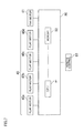
- the indoor unit 1 includes a control unit 80 that controls parameters such as the rotation speed of the air blower 4, and the wind directions of the flaps 35a to 35d.
- the control unit 80 mainly includes a microcomputer equipped with a CPU 81 and memory 82.
- the control unit 80 receives control signals via the wired remote control 83, and, upon receiving the signals, the CPU 81 executes the control program stored in the memory 82 to actuate the fan motor 41 of the air blower 4, and the flap motors 40a to 40d that drive the flaps 35a to 35d. In this way, the control of the rotation speed of the air blower 4 and the wind directions of the flaps 35a to 35d is enabled.
- FIG. 8 is a front view of the wired remote control 83 according to the present embodiment.
- FIG. 9 is a schematic control block diagram of the wired remote control 83.
- FIG. 10 represents various screens displayed in a display section 85 of the wired remote control 83.
- the wired remote control 83 includes a remote control casing 84, the display section 85, various operation buttons 86 to 91, memory 92 storing various data concerning the operation of the indoor unit 1, a CPU 93, and database 94.
- the remote control casing 84 is substantially rectangular in shape, and houses the CPU 93 and other components therein.
- the display section 85 is capable of displaying various settings screens, in addition to a basic screen and various menu screens.
- the operation buttons 86 to 91 are provided on the front face of the remote control casing 84.
- the operate/stop button 86 is a button that a user uses to enter an instruction for starting or stopping the operation of the indoor unit 1.
- the menu/set button 87 is a circular button surrounded by a doughnut-shaped select button 88, and is used by a user when changing the various settings of the indoor unit 1. Pressing the menu/set button 87 enables the display section 85 to display a main menu screen D1.
- the menu/set button 87 also functions to set each setting item selected in the main menu screen D1.
- the select button 88 has an up selector 88u, a down selector 88d, a left selector 881, and a right selector 88r, each marked with the symbol ⁇ indicative of the direction (up, down, left, or right).
- the four selectors 88u to 88r are integral in appearance, and represent the allocated regions up, down, left, and right of the select button 88. Pressing the selector 88u to 88r moves the cursor, enabling a user to select, for example, a setting item or a setting value for the indoor unit 1.
- the mode switch button 89 is a button used to switch the operation mode of the indoor unit 1 between heating mode and cooling mode.
- the wind volume/wind direction button 90 is a button that a user uses to change the total wind volume/total air direction of the outlets 32a to 32d.
- the CPU 93 runs a program to control the operation of the indoor unit 1.
- the database 94 stores various kinds of information, including the layout data for forming a screen displayed in the display section 85. Examples of layout data include basic layout data for forming the basic screen D0 shown in FIG. 10 , main menu layout data for forming the main menu screen D1 shown in FIG. 11 , and detailed settings layout data for the total wind volume/total wind direction adjust screen D2 shown in FIGS. 12 and 13 , the wind direction individual setting screen D3 shown in FIG. 14 , and the wind direction settings check screen D4 shown in FIG. 15 .
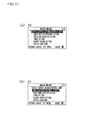
- FIGs. 10 to 15 represent various screens displayed in the display section 85 of the wired remote control 83.
- FIG. 10 (a) and (b) represents examples of the basic screen D0 displayed in the display section 85.
- the basic screen D0 is divided into a display region 100 that indicates the current temperature setting, a display region 101 that indicates the current operation mode setting, a display region 102 that indicates the current wind volume state setting, and a display region 103 that indicates whether the wind directions are individually set for the main outlets 32a to 32d.
- the display region 100 displays the character "26°".
- the display region 100 displays the character "26°C” as the current temperature setting, the display region 101 the character “Cooling” as the current operation mode setting, and the display region 102 the character “Auto” as the current wind volume state setting.
- the display region 103 displays the character "Individual setting" when the wind direction is individually set for at least one of the main outlets 32a to 32d, and does not display any text when the wind direction is not individually set for any of the main outlets 32a to 32d.
- the wind direction is individually set for any of the outlets 32a to 32d, and as such the display region 103 displays the character "Individual setting".
- the display region 103 may display the character "No individual setting" when the wind direction is not individually set for any of the outlets 32a to 32d. Pressing the menu/set button 87 in the basic screen D0 changes the display to the main menu screen D1 shown in FIG. 11 . Pressing the wind volume/wind direction button 90 in the basic screen effects the interrupt processing, and changes the display to the total wind volume adjust screen D2 shown in FIG. 12 .
- FIG. 11(a) and (b) represents examples of the main menu screen D1 displayed in the display section 85.
- the main menu screen D1 has six setting items for the indoor unit 1. Specifically, menu titles are listed that correspond to "Service contact information/model name”, “Wind direction individually setting”, “Check wind direction setting”, “Timer setting”, “Energy saving setting”, and "Useful functions”.
- FIG. 11 (a) represents the initial screen that appears upon switching to the main menu screen D1.
- the cursor is on the menu title corresponding to the setting item "Service contact information/model name" from the different setting items. Pressing the down selector 88d in this state moves the cursor down in the display section 85 in turn, allowing the user to select a setting item by placing the cursor on one of the menu titles "Wind direction individually setting" to "Useful functions”.
- the main menu screen D1 switches to the wind direction individual setting screen D3 shown in FIG. 14 .
- the user can then individually set the wind direction for any of the main outlets 32a to 32d, based on the wind direction individual setting screen D3.
- pressing the menu/set button 87 while the setting item "Check wind direction setting” is selected the main menu screen D1 switches to the wind direction settings check screen D4 shown in FIG. 15 .
- the user can then visually confirm all the wind directions currently set for the main outlets 32a to 32d.
- FIG. 12 (a) to (e) and FIG. 13 (a) to (h) represent examples of the total wind volume/total wind direction adjust screen D2 displayed in the display section 85.
- the total wind volume/total wind direction adjust screen D2 is divided into display regions 104 and 105. Menu titles corresponding to the two setting items "Adjust total wind volume” and "Adjust total wind direction" are displayed in the upper part of each display region.
- FIG. 12 (a) represents the initial screen D2-0 of the total wind volume/total wind direction adjust screen D2.
- the cursor is on the menu title corresponding to the setting item "Adjust total wind volume”.
- the display region 104 in the initial screen displays the character “Rapid” , indicating that the total wind volume is currently “Rapid” for all of the main outlets 32a to 32d.
- the total wind volume of the main outlets 32a to 32d can be set to "Strong” ( FIG. 12 (b) ), “Weak” ( FIG. 12(c) ), or “Auto” ( FIG. 12(d) ).
- Pressing the cancel button 91 in the initial screen D2-0 shown in FIG. 12 (a) switches the display to the basic screen D0 shown in FIG. 10 .
- pressing the down selector 88d in the initial screen D2-0 switches the display to the settings screen D2-1 ( FIG. 12 (b) ), the settings screen D2-2 ( FIG. 12(c) ), and the settings screen D2-3 ( FIG. 12(d) ) in turn.
- Pressing the menu/set button 87 in each display state changes the display in the display region 104 from "Strong” to "Weak", and to "Auto", allowing the user to set the total wind volume for the main outlets 32a to 32d at once.
- the display returns to the previous screen at the pressing of the up selector 88u.
- the main outlets 32a, 32b, and 32d other than the main outlet 32c may be selected by individually setting "Wind direction 1" for the main outlet 32c in advance, and the total wind direction may be set at once only for the wind direction positions of the flaps 35a, 35b, and 35d of the main outlets 32a, 32b, and 32d so selected.
- the text "Wind direction 1" displayed at the center of the display region 105 means that the total wind direction of the main outlets 32a, 32b, 32d is currently set to "Wind direction 1" altogether.
- the total wind direction of the main outlets 32a, 32b, and 32d may be set to any of "Wind direction 2" ( FIG. 13(b) ), “Wind direction 3" ( FIG. 13(c) ), “Wind direction 4" ( FIG. 13(d) ), “Wind direction 5" ( FIG. 13(e) ), and “Swing” ( FIG. 13(f) ).
- Pressing the down selector 88d in the initial screen shown in FIG. 13 (a) switches the display to the settings screen D2-5 ( FIG. 13(b) ), the settings screen D2-6 ( FIG. 13(c) ), the settings screen D2-7 ( FIG. 13(d) ), the settings screen D2-8 ( FIG. 13 (e) ), and the settings screen D2-9 ( FIG. 13 (f) ) in turn, changing the display of the display region 105 from "Wind direction 1" to "Wind direction 5", and to "Swing” in turn. Pressing the menu/set button 87 in each display state enables the total wind direction of the main outlets 32a, 32b, and 32d to be set at once. The display returns to the previous screen at the pressing of the up selector 88u.
- the character "Wind direction individual setting" is displayed to indicate that the wind direction is individually set for any of the main outlets.
- the display may indicate which of the main outlets has an individual wind direction setting. Specifically, in the presently described example, the display may indicate that the wind direction has been individually set for the main outlet 32c. Further, in the screens shown in FIGs. 12 and 13 , the display may indicate which outlet is subject to the "Total wind direction setting”. Specifically, in this example, the display may indicate that the main outlets 32a, 32b, and 32d are the subject of the "Total wind direction setting".
- FIG. 14 (a) to (g) represents examples of the wind direction individual setting screen D3 displayed in the display section 85.
- the wind direction individual setting screen D3 is divided into display regions 106 and 107.
- the display region 106 schematically displays the indoor unit 1 as viewed from the room, and symbols " ⁇ " to " ⁇ " representing the sign sections 60a to 60d of the rim portions 50a to 50d are displayed in the diagram.
- the display region 107 displays the state of the wind direction currently set for the main outlets 32a to 32d.
- FIG. 14(a) represents the initial screen D3-0 for wind direction individual setting.
- the schematic view displayed in the display region 106 includes an inverted display, indicating that the main outlet 32a corresponding to symbol " ⁇ " has been selected.
- the number "1" displayed at the central part of the display region 106 corresponds to the main outlet 32a, and indicates that the main outlet 32a has been selected.
- the inverted display and the number thus provide visual information for a user to confirm that the outlet 32a is available for the individual setting of wind direction.
- the character "wind direction 2" is displayed at the center of the display region 107 in the initial screen D3-0, indicating that the main outlet 32a has been set to "wind direction 2".
- the wind direction of the main outlet 32a can be selected from “wind direction 1" to "wind direction 5" and "Swing" by operating the up selector 88u or the down selector 88d in the state shown in FIG. 14(a) . Pressing the menu/set button 87 while any of the wind directions is selected sets the main outlet 32a to the selected wind direction.
- pressing the cancel button 91 in the state shown in FIG. 14 (a) switches the initial screen D3-0 to the main menu screen D1 shown in FIG. 11 .
- Pressing the right selector 88r in the state shown in FIG. 14(a) switches the initial screen D3-0 to the settings screen D3-1 ( FIG. 14(b) ), the settings screen D3-2 ( FIG. 14 (c) ), and the settings screen D3-3 ( FIG. 14 (d) ) in turn, allowing the user to set any of "wind direction 1" to "wind direction 5" and "Swing" for the main outlets 32b to 32d.
- the following describes how the "wind direction 2" set for the main outlet 32d as in FIG. 14 (d) is changed to "wind direction 3".
- Pressing the down selector 88d in the settings screen D3-3 of FIG. 14 (d) switches the display to the settings screen D3-4 shown in FIG. 14 (e) , and the display at the central part of the display region 107 switches to "wind direction 3".
- Pressing the menu/set button 87 while "wind direction 3" is displayed enables the wind direction of the main outlet 32d to be individually set to "wind direction 3".
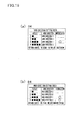
- FIG. 15 (a) and (b) represents examples of the wind direction settings check screen D4 displayed in the display section 85.
- the wind direction settings check screen D4 lists menu titles corresponding to three check items: "Outlet”, “Wind direction”, and "Individual setting", from left to right.
- the column under the check item "Outlet” displays symbols "1 ⁇ " to "4 ⁇ ”for individually identifying the outlets 32a to 32d.
- the symbols "1 ⁇ " to “4 ⁇ ” correspond to the symbols “ ⁇ ” to " ⁇ ” (see FIG. 3 ) for individually identifying the main outlets 32a to 32d. Further, as shown in FIG.
- the column under the check item “Wind direction” displays the wind directions of the main outlets 32a to 32d, simultaneously with the symbols “1 ⁇ ” to "4 ⁇ ”
- the column under the check item “Individual setting” indicates whether the wind direction has been individually set for the main outlets 32a to 32d, and "o" is displayed in the cells corresponding to the individually set main outlets.
- the main outlets 32a, 32b, and 32d have the total wind direction setting "wind direction 2", and only the wind direction of the main outlet 32c has the individual setting "wind direction 1" .
- the symbol “o” is displayed in the cell corresponding to the main outlet 32c.
- the main outlets 32a and 32b have the total wind direction setting "wind direction 2"
- the wind directions of the main outlets and 32c and 32d have the individual settings "wind direction 1" and "wind direction 3", respectively.
- the symbol “o” is displayed in the cells corresponding to the main outlets 32c and 32d under the check item "Individual setting".
- pressing the right selector 88r in the wind direction settings check screen of FIG. 15 (a) and (b) switches the display to the initial screen D3-0 for wind direction individual setting shown in FIG. 14 , enabling a user to individually set the wind direction for any of the main outlets.
- the individual wing direction setting for any of the main outlets may be enabled while the wind direction settings check screen is displayed.
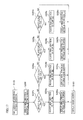
- FIG. 16 is a flowchart representing the wind volume/wind direction adjustment operation of the present embodiment. It should be noted that the "wind volume/wind direction adjustment operation” in the flowchart includes the “total wind volume adjustment operation”, “total wind direction adjustment operation”, “wind direction individual setting operation”, and “wind direction settings check operation”, as will be described later.
- step S100 in FIG. 16 the display section 85 displays the basic screen D0 (see FIG. 10(a) ).
- step S102 it is determined in step S102 whether the wind volume/wind direction button 90 has been pressed. If it is determined that the wind volume/wind direction button 90 has been pressed, the sequence goes to step S104. On the other hand, the sequence goes to step S100 if it is determined that the wind volume/wind direction button 90 has not been pressed.
- the display section 85 displays the total wind volume/total wind direction adjust screen D2 (see FIG. 12(a) to (d) ) for the group setting of the total wind volume for the main outlets 32a to 32d.
- step S106 it is determined whether a request for changing the currently set wind volume for the main outlets 32a to 32d to other wind volume has been entered. If a request for changing to other wind volume has been entered, the sequence goes to step 108, and the total wind volume adjustment operation is performed. On the other hand, the sequence goes to step S110 if a request for wind volume change has not been entered.
- step S110 It is determined in step S110 whether a request for changing the currently set wind direction for the main outlets 32a, 32b, and 32d to other wind direction has been entered. If a request for changing to other wind direction has been entered, the sequence goes to step 112, and the total wind direction adjustment operation is performed. On the other hand, the sequence goes to step S110 if a request for wind volume change has not been entered.
- step S114 the display section 85 displays the basic screen D0.
- the display section 85 displays the main menu screen D1.
- step S118 It is determined in the next step S118 whether a request for confirming the wind direction settings of the main outlets 32a to 32d has been entered. If a request for confirming the wind direction settings of the main outlets 32a to 32d has been entered, the sequence goes to step S120. On the other hand, the sequence goes to step S122 if a request for confirming the wind direction settings of the main outlets 32a to 32d has not been entered.
- step S120 it is determined if a request for individually setting the wind direction of any of the main outlets 32a to 32d has been entered. If a request for individually setting the wind direction of any of the main outlets 32a to 32d has been entered, the sequence goes to step S126 in FIG. 17 . On the other hand, the sequence goes to step S100 if a request for individually setting the wind direction of any of the main outlets 32a to 32d has not been entered.
- step S122 the display section 85 displays the wind direction settings check screen D4, and the sequence goes to step S100.
- FIG. 17 is a flowchart representing the wind direction individual setting operation of the present embodiment.
- step S200 displays the initial screen D3-0 for wind direction individual setting (see FIG. 14 (a) ).
- step S202a it is determined whether the main outlet 32a has been selected. If the main outlet 32a has been selected, the sequence goes to step S204a, and the flap 35a is adjusted to the individually set wind direction.
- step 206a the display section 85 displays the wind direction settings check screen D4. If the main outlet 32a has not been selected, the sequence goes to step S202b. If the main outlet 32b has been selected, the wind direction of the flap 35b is adjusted in step S204b, and the wind direction settings check screen D4 is displayed in step S206b. The same process is performed for the main outlets 32c and 32d in steps S202c to S206c and in steps S202d to S206d, respectively.
- the wind direction individual setting operation is performed in step S126 of FIG. 17 after the total wind volume adjustment operation (step S108) and the total wind direction adjustment operation (step S112) in FIG. 16 .
- the total wind volume adjustment operation (step S108) or the total wind direction adjustment operation (step S112) may be performed by interrupting the currently running wind direction individual setting operation when the wind volume/wind direction button 90 is pressed while performing the wind direction individual setting operation in step S126 of FIG. 17 .
- pieces of information of all the main outlets 32a to 32d or the flaps 35a to 35d are simultaneously listed.
- a user by looking at this list, can grasp the current settings of wind directions of all the main outlets 32a to 32d and the flaps 35a to 35d at once.
- the display section 85 is capable of displaying information corresponding to the sign sections 60a to 60d. Therefore, the flap in need of, for example, wind direction change can be individually identified only by looking at the sign sections 60a to 60d. Further, with the display on the display section 85 corresponding to the sign sections 60a to 60d, the plurality of outlets 32a to 32d are easily recognized.
- a user can easily identify the sign sections 60a to 60d, because the sign sections 60a to 60d are three-dimensionally provided as recessed portions in the rim portions 50a to 50d of the panel lower surface portion 3b. Because the sign sections 60a to 60d are formed on the flat surface of the panel lower surface portion 3b, the sign sections 60a to 60d can easily be recognized from any direction in the room. Specifically, the recognition of the sign sections 60a to 60d from a certain direction in a room can be difficult when the sign sections 60a to 60d are formed on the outer side of the outlets and when the areas bearing the sign sections 60a to 60d are tilted with respect to the ceiling surface. It also can be difficult to recognize the sign sections 60a to 60d depending on the direction in a room when the flap angle is changed for flaps 35a to 35d having the sign sections 60a to 60d directly formed thereon.
- a user can individually identify the main outlets 32a to 32d and the flaps 35a to 35d more reliably, because the sign sections 60a to 60d are provided as figures " ⁇ "to " ⁇ ⁇ ".
- a user can individually identify the main outlets 32a to 32d and the flaps 35a to 35d even more reliably, because the sign sections 60a to 60d corresponding to the main outlets 32a to 32d and the flaps 35a to 35d are formed by the counterclockwise layout of the figures " ⁇ " to " ⁇ ” representing the sign sections 60a to 60d.
- a user can individually identify the main outlets 32a to 32d and the flaps 35a to 35d even more reliably, because the surroundings of the sign sections 60a to 60d are matte finished to make the sign sections 60a to 60d more noticeable in appearance over the surroundings.
- the decorative panel 3 and the sign sections 60a to 60d are integrally formed, it is not necessary to go through the laborious procedure of preparing four flaps of different shapes, which is otherwise necessary when a recessed sign section is to be provided for each flap. This reduces the number of manufacturing steps and the manufacturing cost of the air conditioner 1.
- the air-conditioning air can be sent into the room most efficiently, because the main outlets 32a to 32d are disposed on the panel side portions 30a to 30d, the outermost portions of the product.
- the intake 31 is disposed on the inner side of the main outlets 32a to 32d, the discharged air flow can be prevented from being immediately drawn into the intake.
- the sign sections 60a to 60d are formed on the intake 31 side of the main outlets 32a to 32d, the sign sections 60a to 60d can easily be checked even when the flaps 35a to 35d are moving during the operation.
- a user can easily identify the flaps 35a to 35d by looking at the sign sections 60a to 60d, even when the flaps 35a to 35d have substantially the same shape and make it difficult for the user to individually identify the flaps 35a to 35d.
- usability can be improved, because a user looking at the display section 85 of the wired remote control 83 can simultaneously grasp the main outlets 32a to 32d and the wind directions currently set for the outlets on the wind direction settings check screen D4.
- a user can easily grasp the wind directions of all the main outlets 32a to 32d only by looking at the display section 85, because the wind directions of the main outlets 32a to 32d are displayed in a list on the wind direction settings check screen D4.
- a user can change the wind direction positions of the flaps 35a to 35d with a remote control based on his or her memory of the sign sections corresponding to the outlets or flaps, even when the wired remote control 83 is disposed distant away from the indoor unit 1.
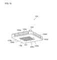
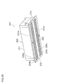
- FIG. 18 is an external perspective view of an indoor unit 101 according to Second Embodiment of the present invention.
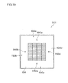
- FIG. 19 is a plan view of an intake grill 108 of the indoor unit 101 as seen from the air-conditioned room.
- the indoor unit 101 is a ceiling-hanging indoor unit including box-shaped casing 103 provided with main outlets 102a to 102d provided as horizontal openings on the four sides of the casing 103.
- the indoor unit 101 is disposed on the ceiling surface (not illustrated).
- a heat exchanger and a turbo fan are housed inside the casing 103.
- Flaps 106a to 106d for adjusting the wind direction of the air-conditioning air into the room are rotatably provided for the main outlets 102a to 102d.
- the intake grill 108 having an intake 107 at the center is mounted on the lower surface of the casing 103 in a manner allowing the intake grill 108 to open and close.
- the intake grill 108 has side portions 150a to 150d in the vicinity of the main outlets 102a to 102d, respectively.
- the main outlets 102a to 102d are formed along the side portions 150a to 150d, respectively.
- the intake 107 is disposed on the inner side of the main outlets 102a to 102d.
- the sign sections 160a to 160d for individually recognizing the main outlets 102a to 102d or the flaps 106a to 106d are formed by attaching stickers, numbered “1" to "4", to the side portions 150a to 150d.
- the numbers “1” to “4" correspond to the main outlets 102a to 102d, respectively, and are arranged in ascending order in the counterclockwise direction in FIG. 19 .
- the sign sections 160a to 160d are formed on the intake 107 side of the main outlets 102a to 102d.
- the same effects obtained for the air conditioner of First Embodiment can be obtained, because the flaps in need of, for example, wind direction change can be individually identified from the flaps 106a to 106d only by looking at the sign sections 160a to 160d formed in the side portions 150a to 150d in the vicinity of the main outlets 102a to 102d.
- sign sections 160a to 160d can easily be formed by attaching stickers numbered "1" to "4" to the side portions 150a to 150d.
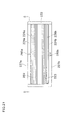
- FIG. 20 is an external perspective view of an indoor unit 201 according to Third Embodiment of the present invention.
- FIG. 21 is a plan view of a decorative panel 222 of the indoor unit 201 as viewed from the air-conditioned room.
- FIG. 22 is a cross sectional view taken at line C-C of FIG. 21 .
- the indoor unit 201 is a ceiling embedded indoor unit, and includes a casing 202 ( FIG. 20 ) in which components such as a fan unit, a heat exchanger, and an electrical component box are contained.
- the casing 202 has a form of a horizontally long rectangle with a decorative panel 222 mounted on a main body casing 221. As illustrated in FIG. 20 , the decorative panel 222 is detachably provided on the main body casing 221, covering the lower surface of the main body casing 221. Horizontally long intakes 223 are provided through the decorative panel 222 at the center, and horizontally long main outlets 224a and 224b are provided along side portions 227a and 227b on the both sides.
- Flaps 226a and 226b for adjusting the wind direction of the air-conditioning air into the room are rotatably provided for the main outlets 224a and 224b.
- an intake grill 225 is detachably mounted on the intakes 223.
- the intakes 223 are disposed on the inner side of the main outlets 224a and 224b.
- sign sections 260a and 260b for individually recognizing the main outlets 224a and 224b and the flaps 226a and 226b are formed on the outer side of the decorative panel 222, in the vicinity of the main outlets 224a and 224b.
- the sign sections 260a and 260b are formed as the figures “ ⁇ ” and “ ⁇ ”.
- the figures " ⁇ " and “ ⁇ ” correspond to the main outlets 224a and 224b, respectively.
- the sign sections 260a and 260b are formed opposite from the intakes 223 with respect to the main outlets 224a and 224b.
- the sign sections 260a and 260b are three-dimensionally provided as raised portions on the decorative panel 222.
- the same effects obtained for the air conditioner of First Embodiment can be obtained, because the flaps in need of, for example, wind direction change can be individually identified from the flaps 226a and 226b only by looking at the sign sections 260a and 260b formed in the vicinity of the main outlets 224a and 224b.
- the sign sections are realized by the sign sections 60a to 60d formed as recessed portions in the rim portions 50a to 50d.
- the sign sections are realized by the sign sections 160a to 160d formed by attaching stickers numbered "1" to "4" to the side portions 150a to 150d.
- the sign sections are realized by the sign sections 260a and 260b formed as raised portions on the decorative panel 222.
- the present invention is not limited to these specific embodiments.
- the outlets or flaps may be individually recognized by changing the color of each flap. Alternatively, as illustrated in FIG.
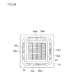
- the sign sections 60a to 60d may be formed on the outer side of the outlets 32a to 32d on the panel main body 3a. Further, as illustrated in FIG. 24 , the sign sections 60a to 60d may be directly formed on the flaps 35a to 35d.
- the sign sections 60a to 60d are described as being relatively glossier than the matte finished surroundings.
- the present invention is not limited to this embodiment.
- the sign sections may be actively treated to be glossy, or may include a portion (gloss portion) where a luminous fluorescent coating that glows in the dark is applied.
- the sign sections may be color displayed using, for example, an LED (light emitting portion), or an LED (light emitting portion) or other light emitting materials may be provided inside the transparent resin forming the flaps 35a to 35d.
- the sign sections 60a to 60d corresponding to the outlets 32a to 32d and the flaps 35a to 35d are described as being formed by the counterclockwise arrangement of the figures " ⁇ " representing the sign sections 60a to 60d.
- the present invention is not limited to this embodiment.
- the sign sections 60a to 60d may be formed by the clockwise arrangement of the figures " ⁇ " representing the sign sections 60a to 60d. Further, the clockwise/counterclockwise layout may not even be necessary.
- the present invention is described as being applied to the indoor unit 1 that includes the panel main body 3a provided with the main outlets 32a to 32d and the auxiliary outlets 32e to 32h.
- the present invention is not limited to this embodiment.
- the present invention is also applicable to an indoor unit that includes a panel main body provided only with the main outlets 32a to 32d.
- the indoor unit 1 is controlled by using the wired remote control 83 connected to the main body of the indoor unit 1 via the communication cable.
- the air conditioner may be controlled by using a radio-transmission wireless remote control that does not make use of a communication cable for interconnection with the main body of the indoor unit 1.
- the total wind volume of the outlets 32a to 32d is adjusted with a single fan motor 41 provided for the outlets 32a to 32d, and with a single impeller 42 that rotates by being joined to the fan motor 41.
- the wind volume may be individually adjusted for the outlets 32a to 32d with a fan motor and an impeller provided for each of the outlets 32a to 32d.
- the state of each wind volume of the outlets 32a to 32d may be displayed in a list in the display section 85.
- the operation mode hereinating/cooling
- the operating condition for each of the outlets 32a to 32d may be displayed in a list in the display section 85.
- the display region 105 is adapted to display "wind direction 1" to "wind direction 5" and "Swing".
- the present invention is not limited to this embodiment.
- the display section 105 may display "Fully closed", indicating that the flaps are fully closed.
- the wind direction of the main outlet 32c is set to "wind direction 1" in advance, and the wind direction positions of only the selected flaps 35a, 35b, and 35d are changed at once.
- the present invention is not limited to this embodiment.
- the wind direction positions of the selected flaps 35a, 35b, and 35d may be directly changed without setting the wind direction of the main outlet 32c to "wind direction 1" in advance.
- the remote control 83 and the indoor unit 1 are connected to each other via the communication cable W.
- the present invention is not limited to this embodiment.
- the remote control may be connected to the outdoor unit via a wire, and the operation signals from the remote control may be sent first to the outdoor unit, and then to the indoor unit 1 with the supplied power from the outdoor unit.
- wind direction settings check screen D4 simultaneously displays information indicative of the discharge directions of the air-conditioning air from the four main outlets 32a to 32d.
- the wind direction settings check screen D4 may simultaneously display information (e.g., information indicative of the discharge directions of the air-conditioning air) of selected ones of the four main outlets 32a to 32d (two or three main outlets).
- the wind direction settings check screen D4 may simultaneously display information (e.g., information indicative of the angles of the flaps) of all the four flaps 35a to 35, or simultaneously display information of selected ones of the four flaps 35a to 35d (two or three flaps).
- the wind direction settings check screen D4 may simultaneously display information of selected ones of the four main outlets 32a to 32d, and information of selected ones of the four flaps 35a to 35d.
Landscapes
- Engineering & Computer Science (AREA)
- Chemical & Material Sciences (AREA)
- Combustion & Propulsion (AREA)
- Mechanical Engineering (AREA)
- General Engineering & Computer Science (AREA)
- Human Computer Interaction (AREA)
- Air Conditioning Control Device (AREA)
- Air Filters, Heat-Exchange Apparatuses, And Housings Of Air-Conditioning Units (AREA)
Abstract
Description
- The present invention relates to a controller and an air conditioner having the same, the controller being configured to accept operations entered for the air conditioner.
- The ceiling embedded indoor unit has a plurality of outlets for the discharge of air-conditioning air. The outlets have flaps disposed to change the discharge direction of the air-conditioning air (see, for example, Patent Document 1). In this indoor unit, the operation of the flaps is controlled by a single motor.
-
- Patent Document 1:
JP-A-2005-207705 - In an air conditioner that includes the indoor unit having a plurality of flaps respectively disposed at the outlets, it is conceivable to individually control the flaps. In this air conditioner, the wind directions of the plurality of outlets are preferably displayed by the controller so that the user can easily confirm.
- It is accordingly an object of the present invention to provide a controller configured so that pieces of information relating to each outlet and each flap which are currently set can be collectively visible, and to provide an air conditioner having such a controller.
- A first aspect of the present invention is a controller for an indoor unit that includes a plurality of flaps of substantially the same shape respectively disposed at a plurality of outlets, and capable of individually changing the discharge direction of the air-conditioning air, comprising a display section that displays at least two pieces of information of selected ones of the plurality of outlets and/or selected ones of the plurality of flaps.
- With this controller, pieces of information of all the outlets and/or the flaps are simultaneously listed. A user, by looking at this list, can grasp the current settings of all the outlets and flaps at once.
- A second aspect of the present invention is the controller of the first aspect, further comprising: an operation section that accepts an operation entered to control the position of the plurality of flaps, wherein the display section simultaneously displays information indicative of the discharge directions of the air-conditioning air from selected ones of the plurality of outlets.
- With this controller, the user can visually conf irm on the display section the wind directions currently set for the outlets.
- A third aspect of the present invention is the controller of the first aspect, adapted so that: in the indoor unit, different sign sections are respectively provided either in the vicinity of the plurality of outlets or on the plurality of flaps; and the display section is capable of displaying information corresponding to the sign sections.
- With this controller, the flap in need of, for example, wind direction change can be individually identified only by looking at the sign sections formed in the vicinity of the plurality of outlets or on the plurality of flaps. Further, with the display on the display section corresponding to the sign sections, the plurality of outlets or the plurality of flaps are easily recognized.
- A fourth aspect of the present invention is the controller of the third aspect, adapted so that the display section is capable of displaying information corresponding to the sign sections simultaneously with information indicative of the discharge directions of the air-conditioning air at the outlets indicated by the sign sections.
- With the controller, usability can be improved, because a user looking at the display section can simultaneously grasp the outlets and the discharge directions currently set for the outlets.
- A fifth aspect of the present invention is the controller of the second aspect, adapted so that the operation section enables the positions of the plurality of flaps to be individually changed so as to change the discharge direction of the air-conditioning air at the plurality of outlets.
- With this controller, the positions of the flaps can be individually changed.
- A sixth aspect of the present invention is the controller of the second aspect, adapted so that the operation section enables the positions of the plurality of flaps to be changed at once so as to change the discharge direction of the air-conditioning air at the plurality of outlets.
- With this controller, the position of each flap can be changed at once without accompanying individual operations for the flaps.
- A seventh aspect of the present invention is the controller of the sixth aspect, adapted so that the operation section enables the positions of the selected ones of the plurality of flaps to be changed at once so as to change the discharge direction of the air-conditioning air at the plurality of outlets.
- With this controller, the positions of only the selected flaps can be changed at once.
- An eighth aspect of the present invention is the controller of the first aspect, connected to an air conditioner via a wire.
- Although the controller is a wired remote control, pieces of information of the outlets and the flaps are simultaneously displayed in a list as in the case of the wireless remote control.
- A ninth aspect of the present invention is an air conditioner comprising the controller according to any one of the first to eighth aspects.
- In this air conditioner, the same advantages obtained with the controller of any one of the first to eighth aspects can be obtained.
- A tenth aspect of the present invention is the air conditioner of the ninth aspect, adapted so that, in the indoor unit, different sign sections are respectively provided either in the vicinity of the plurality of outlets or on the plurality of flaps.
- In this air conditioner, the flap in need of, for example, wind direction change can easily be identified only by looking at the sign sections formed in the vicinity of the plurality of outlets or on the plurality of flaps.
- An eleventh aspect of the present invention is the air conditioner of the tenth aspect, adapted so that the sign sections are three-dimensionally provided as raised portions or recessed portions.
- In this air conditioner, a user can easily identify the sign sections, because the sign sections are three-dimensionally provided as raised portions or recessed portions.
- A twelfth aspect of the present invention is the air conditioner of the tenth aspect, adapted so that, in the indoor unit, the sign sections are provided by being printed or by attaching stickers.
- In the air conditioner, the sign sections can easily be formed by being printed or by attaching stickers.
- A thirteenth aspect of the present invention is the air conditioner of any one of the tenth to twelfth aspects, adapted so that the sign sections are provided as characters, figures, or combinations of characters and figures.
- In this air conditioner, a user can individually identify the outlets and the flaps more reliably, because the sign sections are provided as characters, figures, or combinations of characters and figures.
- As described above, the present invention has the following effects.
- With the first aspect, pieces of information of all the outlets and/or the flaps are simultaneously listed. A user, by looking at this list, can grasp the current settings of all the outlets and flaps at once.
- Further, with the second aspect, the user can visually confirm on the display section the wind directions currently set for the outlets.
- Further, with the third aspect, the flap in need of, for example, wind direction change can be individually identified only by looking at the sign sections formed in the vicinity of the plurality of outlets or on the plurality of flaps. Further, with the display on the display section corresponding to the sign sections, the plurality of outlets or the plurality of flaps are easily recognized.
- Further, with the fourth aspect, usability can be improved, because a user looking at the display section can simultaneously grasp the outlets and the discharge directions currently set for the outlets.
- Further, with the fifth aspect, the positions of the flaps can be individually changed.
- Further, with the sixth aspect, the position of each flap can be changed at once without accompanying individual operations for the flaps.
- Further, with the seventh aspect, the positions of only the selected flaps can be changed at once.
- Further, with the eighth aspect, although the controller is a wired remote control, pieces of information of the outlets and the flaps are simultaneously displayed in a list as in the case of the wireless remote control.
- Further, with the ninth aspect, the same advantages obtained with any one of the first to eighth aspects can be obtained.
- Further, with the tenth aspect, the flap in need of, for example, wind direction change can easily be identified only by looking at the sign sections formed in the vicinity of the plurality of outlets or on the plurality of flaps.
- Further, with the eleventh aspect, a user can easily identify the sign sections, because the sign sections are three-dimensionally provided as raised portions or recessed portions.
- Further, with the twelfth aspect, the sign sections can easily be formed by being printed or by attaching stickers.
- Further, with the thirteenth aspect, a user can individually identify the outlets and the flaps more reliably, because the sign sections are provided as characters, figures, or combinations of characters and figures.
-
-
FIG. 1 is an external perspective view of the indoor unit according to First Embodiment of the present invention. -
FIG. 2 is a schematic planar cross sectional view of the indoor unit. -
FIG. 3 is a cross sectional view taken at line A-O-A ofFIG. 2 . -
FIG. 4 is a plan view of a decorative panel of the indoor unit as viewed from an air-conditioned room. -
FIG. 5 is an enlarged view ofFIG. 3 , illustrating a channel portion corresponding to a main outlet. -
FIG. 6 is a cross sectional view taken at line B-B ofFIG. 4 . -
FIG. 7 is a schematic control block diagram of the indoor unit. -
FIG. 8 is a front view of a wired remote control according to the embodiment of the invention. -
FIG. 9 is a schematic control block diagram of the wired remote control. -
FIG. 10 is a diagram representing a screen displayed in a display section of the wired remote control. -
FIG. 11 is a diagram representing a screen displayed in a display section of the wired remote control. -
FIG. 12 is a diagram representing a screen displayed in a display section of the wired remote control. -
FIG. 13 is a diagram representing a screen displayed in a display section of the wired remote control. -
FIG. 14 is a diagram representing a screen displayed in a display section of the wired remote control. -
FIG. 15 is a diagram representing a screen displayed in a display section of the wired remote control. -
FIG. 16 is a flowchart representing the wind volume/wind direction adjustment operation of the embodiment of the invention. -
FIG. 17 is a flowchart representing the wind direction individual setting operation of the embodiment of the invention. -
FIG. 18 is an external perspective view of the indoor unit according to Second Embodiment of the present invention. -
FIG. 19 is a plan view of a decorative panel of the indoor unit as viewed from an air-conditioned room. -
FIG. 20 is an external perspective view of the indoor unit according to Third Embodiment of the present invention. -
FIG. 21 is a plan view of a decorative panel of the indoor unit as viewed from an air-conditioned room. -
FIG. 22 is a cross sectional view taken at line C-C ofFIG. 21 . -
FIG. 23 is a diagram illustrating a variation of the indoor unit according to First Embodiment of the present invention. -
FIG. 24 is a diagram illustrating a variation of the indoor unit according to First Embodiment of the present invention. - The indoor unit and the air conditioner according to First Embodiment of the present invention are described below with reference to the accompanying drawings.
-
FIG. 1 is an external perspective view of anindoor unit 1 according to First Embodiment of the present invention.FIG. 2 is a schematic planar cross sectional of theindoor unit 1.FIG. 3 is a cross sectional view taken at line A-O-A ofFIG. 2 .FIG. 4 is a plan view of a decorative panel of theindoor unit 1 as viewed from an air-conditioned room.FIG. 5 is an enlarged view ofFIG. 3 , illustrating a channel portion corresponding to amain outlet 32d.FIG. 6 is a cross sectional view taken at line B-B ofFIG. 4 . - As illustrated in
FIG. 1 , theindoor unit 1 is a ceiling embedded indoor unit, and includes acasing 2 housing various constituting units therein. Thecasing 2 is configured from a casingmain body 2a, and adecorative panel 3 disposed under the casingmain body 2a. The casingmain body 2a, as illustrated inFIG. 3 , is disposed by being inserted into the opening formed in ceiling U of an air-conditioned room. Thedecorative panel 3 is fitted to the opening of the ceiling U. Theindoor unit 1 can be controlled by the operation of a wiredremote control 83 connected via a communication cable W (wire) laid along the ceiling surface (not illustrated). - As illustrated in
FIGs. 2 and3 , the casingmain body 2a is box-like in shape with a substantially octagonal open bottom of alternating longer sides and shorter sides as seen in a planar view, and includes a substantially octagonaltop board 21 formed by the continuous and alternating longer sides and shorter sides, andside boards 22 extending downward from the peripheries of thetop board 21. Theside boards 22 includeside boards 22a to 22d corresponding the longer sides of thetop board 21, andside boards 22e to 22h corresponding to the shorter sides of thetop board 21. For example, as illustrated inFIG. 2 , theside board 22a and theside board 22b are disposed substantially orthogonal to each other via theside board 22e. Theside boards side boards side boards - The
side board 22e is disposed at an about 135 degree angle with respect to theadjacent side boards side boards side board 22e. Note that theside board 22f has a different shape from the other side boards, because theside board 22f is where a refrigerant pipe provided for the exchange of a refrigerant between aheat exchanger 6 and an outdoor unit (not illustrated) passes through. Theside boards 22e to 22h are each provided with a fixingbracket 23 used to install the casingmain body 2a in the ceiling space. In the casingmain body 2a, the lengths of the longer and shorter sides of thetop board 21 are set so that the shape including the fixingbrackets 23 appears substantially rectangular as seen in a planar view. - As illustrated in
FIGs. 1 and4 , thedecorative panel 3 is a substantially rectangular plate unit as seen in a planar view, and configured from mainly a panelmain body 3a fixed to the bottom portions of the casingmain body 2a. The panelmain body 3a has alternately and continuously formed fourpanel side portions 30a to 30d (side portions) and fourpanel corner portions 30e to 30h. Thepanel side portions 30a to 30d correspond to theside boards 22a to 22d, respectively, of the casingmain body 2a. Thepanel corner portions 30e to 30h correspond to theside boards 22e to 22h, respectively, of the casingmain body 2a. - As illustrated in
FIG. 1 , the panelmain body 3a includes anintake 31 formed substantially at the center to draw air from the air-conditioned room, and fourmain outlets 32a to 32d, respectively corresponding to thepanel side portions 30a to 30d, through which the air inside the casingmain body 2a discharges into the air-conditioned room. In the present embodiment, theintake 31 is a substantially square opening. The fourmain outlets 32a to 32d have substantially the same shape, and are disposed along thepanel side portions 30a to 30d, respectively. - Further, as illustrated in
FIGs. 1 and4 , the panelmain body 3a includesauxiliary outlets 32e to 32h, corresponding in position to thepanel corner portions 30e to 30h, respectively. Further, as illustrated inFIG. 1 , a four-sided, flat annular, panellower surface portion 3b is provided around theintake 31 on the lower surface of the panelmain body 3a by being surrounded by the fourmain outlets 32a to 32d. As illustrated inFIG. 4 , the panellower surface portion 3b hasrim portions 50a to 50d in the vicinity of themain outlets 32a to 32d, on theintake 31 side of themain outlets 32a to 32d. - As illustrated in
FIG. 4 , theintake 31 is disposed on the inner side of themain outlets 32a to 32d. Theintake 31 includes anintake grill 33, and afilter 34 provided to remove dust in the air drawn through theintake 31. Further, as illustrated inFIG. 4 , themain outlets 32a to 32d are provided withflaps 35a to 35d, respectively, that are swingable about an axis along the longitudinal direction. Theflaps 35a to 35d are long, narrow substantially rectangular blade members of substantially the same shape extending along the longitudinal direction of their respectivemain outlets 32a to 32d. Theflaps 35a to 35d are swingable about an axis along the longitudinal direction of themain outlets 32a to 32d by being rotatably supported on thedecorative panel 3. - As illustrated in
FIG. 4 , signsections 60a to 60d for individually recognizing themain outlets 32a to 32d or theflaps 35a to 35d are formed on therim portions 50a to 50d of the panellower surface portion 3b. Thesign sections 60a to 60d are formed as figures "□", "□ □", "□ □ □", and "□□□□". Thesign sections 60a to 60d are formed on theintake 31 side of themain outlets 32a to 32d. The figures "□" to "□□□□" correspond to numbers "1" to "4", respectively, which, inFIG. 4 , are arranged in ascending order in the counterclockwise direction. The figures "□" to "□□□□" are disposed in positions corresponding to themain outlets 32a to 32d, respectively. As illustrated inFIG. 6 , thesign sections 60a to 60d are three-dimensionally "□□□□" provided as recessed portions in therim portions 50a to 50d. Note that the areas surrounding thesign sections 60a to 60d are matte finished (surface texturing), whereas the sign sections are more glossy (gloss portions) relative to the surroundings. - The
flaps 35a to 35d can be set to the swing state that involves continuous driving byflap motors 40a to 40d (seeFIG. 7 ), or the stationary state in which the discharge direction of air-conditioning air is fixed. In the swing state setting, theflaps 35a to 35d continuously swing to change the discharge direction of the air-conditioning air. On the other hand, in the stationary state setting, theflaps 35a to 35d assume the predetermined wind direction position and fix the discharge direction of the air-conditioning air in a certain direction. As illustrated inFIG. 4 , theflaps 35a to 35d can swing to individually change the wind directions of the air flow X discharged into the air-conditioned room through themain outlets 32a to 32d. - For example, as illustrated in
FIG. 5 , the wind direction of the air flow X discharged into the air-conditioned room through themain outlet 32d can be varied by theflap 35d upwardly and downwardly with respect to the lower surface of the ceiling U. As illustrated inFIG. 5 , the wind direction of the air flow X can have six settings: "wind direction 1" to "wind direction 5", and "swing" in which the flaps swing over the range of "wind direction 1" to "wind direction 5". The wind directions are set so that the wind is sloped more downwardly with increasing numbers from "wind direction 1" to "wind direction 5". Note that the wind directions of the air flow X discharged into the air-conditioned room through the othermain outlets 32a to 32c are also variable upwardly and downwardly with respect to the lower surface of the ceiling U, and can have any of the six settings, though not described. - As illustrated in
FIG. 3 , inside the casingmain body 2a are provided mainly anair blower 4 that blows air towards the periphery after drawing the air inside the air-conditioned room into the casingmain body 2a through theintake 31 of thedecorative panel 3, and aheat exchanger 6 disposed around the periphery of theair blower 4. In the present embodiment, theair blower 4 is a turbo fan, and includes afan motor 41 provided at the center of thetop board 21 of the casingmain body 2a, and animpeller 42 joined to and rotated by thefan motor 41. - The
impeller 42 includes a disc-shapedend plate 43 joined to thefan motor 41, a plurality ofblades 44 provided at the periphery on the lower surface of theend plate 43, and a disc-shapedend ring 45 provided on the lower side of theblades 44 and having an opening at the center. By the rotation of theblades 44, theair blower 4 can draw air into theimpeller 42 through the opening of theend ring 45, and can discharge the intake air in theimpeller 42 towards the periphery of theimpeller 42. - In the present embodiment, the
heat exchanger 6 is a cross-fin-tube heat exchanger panel formed by being bent around the periphery of theair blower 4, and is connected via a refrigerant pipe to an outdoor unit (not illustrated) installed, for example, outside. Theheat exchanger 6 is adapted to serve as an evaporator for the passing refrigerant in cooling mode, and as a condenser for the passing refrigerant in heating mode. In this way, theheat exchanger 6 can cool air in cooling mode and heat air in heating mode by the heat exchange of the air drawn into the casingmain body 2a through theintake 31 by theair blower 4. - A
drain pan 7 for receiving drained water generated by the condensation of the air moisture in theheat exchanger 6 is disposed on the lower side of theheat exchanger 6. Thedrain pan 7 is attached to the lower portion of the casingmain body 2a. As illustrated inFIGs. 2 and3 , thedrain pan 7 includes fourmain discharge holes 72a to 72d in communication with themain outlets 32a to 32d of thedecorative panel 3, and a drainedwater receptacle groove 73 formed on the lower side of theheat exchanger 6 to receive the drained water. Themain discharge holes 72a to 72d are shorter along the longitudinal direction of their respectivemain outlets 32a to 32d. The length of themain discharge hole 72c is particularly shorter along the longitudinal direction than the lengths of the othermain discharge holes main discharge hole 72c is interposed between adrain pump 8 disposed on theside board 22g side and used to drain the drained water accumulated in the drainedwater receptacle groove 73, and the portion where the refrigerant pipe running on theside board 22h side passes through. - As illustrated in
FIG. 7 , theindoor unit 1 includes acontrol unit 80 that controls parameters such as the rotation speed of theair blower 4, and the wind directions of theflaps 35a to 35d. Thecontrol unit 80 mainly includes a microcomputer equipped with aCPU 81 andmemory 82. Thecontrol unit 80 receives control signals via the wiredremote control 83, and, upon receiving the signals, theCPU 81 executes the control program stored in thememory 82 to actuate thefan motor 41 of theair blower 4, and theflap motors 40a to 40d that drive theflaps 35a to 35d. In this way, the control of the rotation speed of theair blower 4 and the wind directions of theflaps 35a to 35d is enabled. -
FIG. 8 is a front view of the wiredremote control 83 according to the present embodiment.FIG. 9 is a schematic control block diagram of the wiredremote control 83.FIG. 10 represents various screens displayed in adisplay section 85 of the wiredremote control 83. - As illustrated in
FIG. 8 , the wiredremote control 83 includes a remote control casing 84, thedisplay section 85,various operation buttons 86 to 91,memory 92 storing various data concerning the operation of theindoor unit 1, aCPU 93, anddatabase 94. The remote control casing 84 is substantially rectangular in shape, and houses theCPU 93 and other components therein. Thedisplay section 85 is capable of displaying various settings screens, in addition to a basic screen and various menu screens. - The
operation buttons 86 to 91 (operation sections) are provided on the front face of theremote control casing 84. The operate/stop button 86 is a button that a user uses to enter an instruction for starting or stopping the operation of theindoor unit 1. The menu/set button 87 is a circular button surrounded by a doughnut-shapedselect button 88, and is used by a user when changing the various settings of theindoor unit 1. Pressing the menu/set button 87 enables thedisplay section 85 to display a main menu screen D1. The menu/set button 87 also functions to set each setting item selected in the main menu screen D1. - The
select button 88 has an upselector 88u, adown selector 88d, aleft selector 881, and aright selector 88r, each marked with the symbol Δ indicative of the direction (up, down, left, or right). The fourselectors 88u to 88r are integral in appearance, and represent the allocated regions up, down, left, and right of theselect button 88. Pressing theselector 88u to 88r moves the cursor, enabling a user to select, for example, a setting item or a setting value for theindoor unit 1. - The
mode switch button 89 is a button used to switch the operation mode of theindoor unit 1 between heating mode and cooling mode. The wind volume/wind direction button 90 is a button that a user uses to change the total wind volume/total air direction of theoutlets 32a to 32d. TheCPU 93 runs a program to control the operation of theindoor unit 1. Thedatabase 94 stores various kinds of information, including the layout data for forming a screen displayed in thedisplay section 85. Examples of layout data include basic layout data for forming the basic screen D0 shown inFIG. 10 , main menu layout data for forming the main menu screen D1 shown inFIG. 11 , and detailed settings layout data for the total wind volume/total wind direction adjust screen D2 shown inFIGS. 12 and13 , the wind direction individual setting screen D3 shown inFIG. 14 , and the wind direction settings check screen D4 shown inFIG. 15 . -
FIGs. 10 to 15 represent various screens displayed in thedisplay section 85 of the wiredremote control 83. -
FIG. 10 (a) and (b) represents examples of the basic screen D0 displayed in thedisplay section 85. As shown inFIG. 10 , the basic screen D0 is divided into adisplay region 100 that indicates the current temperature setting, adisplay region 101 that indicates the current operation mode setting, adisplay region 102 that indicates the current wind volume state setting, and adisplay region 103 that indicates whether the wind directions are individually set for themain outlets 32a to 32d. - As shown in
FIG. 10(a) , thedisplay region 100 displays the character "26°". InFIG. 10(b) , thedisplay region 100 displays the character "26°C" as the current temperature setting, thedisplay region 101 the character "Cooling" as the current operation mode setting, and thedisplay region 102 the character "Auto" as the current wind volume state setting. - The
display region 103 displays the character "Individual setting" when the wind direction is individually set for at least one of themain outlets 32a to 32d, and does not display any text when the wind direction is not individually set for any of themain outlets 32a to 32d. InFIG. 10(a) and (b) , the wind direction is individually set for any of theoutlets 32a to 32d, and as such thedisplay region 103 displays the character "Individual setting". Thedisplay region 103 may display the character "No individual setting" when the wind direction is not individually set for any of theoutlets 32a to 32d. Pressing the menu/set button 87 in the basic screen D0 changes the display to the main menu screen D1 shown inFIG. 11 . Pressing the wind volume/wind direction button 90 in the basic screen effects the interrupt processing, and changes the display to the total wind volume adjust screen D2 shown inFIG. 12 . -
FIG. 11(a) and (b) represents examples of the main menu screen D1 displayed in thedisplay section 85. As shown inFIG. 11 , the main menu screen D1 has six setting items for theindoor unit 1. Specifically, menu titles are listed that correspond to "Service contact information/model name", "Wind direction individually setting", "Check wind direction setting", "Timer setting", "Energy saving setting", and "Useful functions". -
FIG. 11 (a) represents the initial screen that appears upon switching to the main menu screen D1. In the initial screen, the cursor is on the menu title corresponding to the setting item "Service contact information/model name" from the different setting items. Pressing thedown selector 88d in this state moves the cursor down in thedisplay section 85 in turn, allowing the user to select a setting item by placing the cursor on one of the menu titles "Wind direction individually setting" to "Useful functions". - For example, as shown in
FIG. 11 (b) , pressing the menu/set button 87 while the setting item "Wind direction individually setting" is selected, the main menu screen D1 switches to the wind direction individual setting screen D3 shown inFIG. 14 . The user can then individually set the wind direction for any of themain outlets 32a to 32d, based on the wind direction individual setting screen D3. Further, for example, pressing the menu/set button 87 while the setting item "Check wind direction setting" is selected, the main menu screen D1 switches to the wind direction settings check screen D4 shown inFIG. 15 . On the wind direction settings check screen D4, the user can then visually confirm all the wind directions currently set for themain outlets 32a to 32d. -
FIG. 12 (a) to (e) andFIG. 13 (a) to (h) represent examples of the total wind volume/total wind direction adjust screen D2 displayed in thedisplay section 85. As shown inFIGs. 12 and13 , the total wind volume/total wind direction adjust screen D2 is divided intodisplay regions -
FIG. 12 (a) represents the initial screen D2-0 of the total wind volume/total wind direction adjust screen D2. In the initial screen, the cursor is on the menu title corresponding to the setting item "Adjust total wind volume". Thedisplay region 104 in the initial screen displays the character "Rapid" , indicating that the total wind volume is currently "Rapid" for all of themain outlets 32a to 32d. The total wind volume of themain outlets 32a to 32d can be set to "Strong" (FIG. 12 (b) ), "Weak" (FIG. 12(c) ), or "Auto" (FIG. 12(d) ). - Pressing the cancel
button 91 in the initial screen D2-0 shown inFIG. 12 (a) , switches the display to the basic screen D0 shown inFIG. 10 . On the other hand, pressing thedown selector 88d in the initial screen D2-0 switches the display to the settings screen D2-1 (FIG. 12 (b) ), the settings screen D2-2 (FIG. 12(c) ), and the settings screen D2-3 (FIG. 12(d) ) in turn. Pressing the menu/set button 87 in each display state changes the display in thedisplay region 104 from "Strong" to "Weak", and to "Auto", allowing the user to set the total wind volume for themain outlets 32a to 32d at once. The display returns to the previous screen at the pressing of theup selector 88u. - Pressing the
right selector 88r in the state shown inFIG. 12 (a) , moves the cursor to the menu title corresponding to the setting item "Adjust total wind direction", and the initial screen D2-0 shown inFIG. 12 (a) switches to the initial screen D2-4 for total wind direction adjustment shown inFIG. 13 (a) . Note that, in this example, the text "Wind direction individual setting" displayed in the lower part of thedisplay region 105 in the initial screen means that the wind direction has been individually set to "Winddirection 1" for themain outlet 32c, and the total wind direction for the remainingmain outlets main outlet 32c is set at once, as follows. As an example, themain outlets main outlet 32c may be selected by individually setting "Wind direction 1" for themain outlet 32c in advance, and the total wind direction may be set at once only for the wind direction positions of theflaps main outlets Wind direction 1" displayed at the center of thedisplay region 105 means that the total wind direction of themain outlets direction 1" altogether. The total wind direction of themain outlets Wind direction 2" (FIG. 13(b) ), "Wind direction 3" (FIG. 13(c) ), "Wind direction 4" (FIG. 13(d) ), "Wind direction 5" (FIG. 13(e) ), and "Swing" (FIG. 13(f) ). - Pressing the
down selector 88d in the initial screen shown inFIG. 13 (a) switches the display to the settings screen D2-5 (FIG. 13(b) ), the settings screen D2-6 (FIG. 13(c) ), the settings screen D2-7 (FIG. 13(d) ), the settings screen D2-8 (FIG. 13 (e) ), and the settings screen D2-9 (FIG. 13 (f) ) in turn, changing the display of thedisplay region 105 from "Wind direction 1" to "Winddirection 5", and to "Swing" in turn. Pressing the menu/set button 87 in each display state enables the total wind direction of themain outlets up selector 88u. - In the screens shown in
FIGs. 12 and13 , the character "Wind direction individual setting" is displayed to indicate that the wind direction is individually set for any of the main outlets. However, the display may indicate which of the main outlets has an individual wind direction setting. Specifically, in the presently described example, the display may indicate that the wind direction has been individually set for themain outlet 32c. Further, in the screens shown inFIGs. 12 and13 , the display may indicate which outlet is subject to the "Total wind direction setting". Specifically, in this example, the display may indicate that themain outlets -
FIG. 14 (a) to (g) represents examples of the wind direction individual setting screen D3 displayed in thedisplay section 85. As shown inFIG. 14 , the wind direction individual setting screen D3 is divided intodisplay regions display region 106 schematically displays theindoor unit 1 as viewed from the room, and symbols "□" to "□□□□" representing thesign sections 60a to 60d of therim portions 50a to 50d are displayed in the diagram. Thedisplay region 107 displays the state of the wind direction currently set for themain outlets 32a to 32d. -
FIG. 14(a) represents the initial screen D3-0 for wind direction individual setting. In the initial screen D3-0, the schematic view displayed in thedisplay region 106 includes an inverted display, indicating that themain outlet 32a corresponding to symbol "□" has been selected. Further, in the initial screen D3-0, the number "1" displayed at the central part of thedisplay region 106 corresponds to themain outlet 32a, and indicates that themain outlet 32a has been selected. The inverted display and the number thus provide visual information for a user to confirm that theoutlet 32a is available for the individual setting of wind direction. Further, as shown inFIG. 14 (a) , the character "wind direction 2" is displayed at the center of thedisplay region 107 in the initial screen D3-0, indicating that themain outlet 32a has been set to "wind direction 2". - The wind direction of the
main outlet 32a can be selected from "wind direction 1" to "wind direction 5" and "Swing" by operating theup selector 88u or thedown selector 88d in the state shown inFIG. 14(a) . Pressing the menu/set button 87 while any of the wind directions is selected sets themain outlet 32a to the selected wind direction. On the other hand, pressing the cancelbutton 91 in the state shown inFIG. 14 (a) , switches the initial screen D3-0 to the main menu screen D1 shown inFIG. 11 . Pressing theright selector 88r in the state shown inFIG. 14(a) , switches the initial screen D3-0 to the settings screen D3-1 (FIG. 14(b) ), the settings screen D3-2 (FIG. 14 (c) ), and the settings screen D3-3 (FIG. 14 (d) ) in turn, allowing the user to set any of "wind direction 1" to "wind direction 5" and "Swing" for themain outlets 32b to 32d. - As an example, the following describes how the "
wind direction 2" set for themain outlet 32d as inFIG. 14 (d) is changed to "wind direction 3". Pressing thedown selector 88d in the settings screen D3-3 ofFIG. 14 (d) switches the display to the settings screen D3-4 shown inFIG. 14 (e) , and the display at the central part of thedisplay region 107 switches to "wind direction 3". Pressing the menu/set button 87 while "wind direction 3" is displayed enables the wind direction of themain outlet 32d to be individually set to "wind direction 3". -
FIG. 15 (a) and (b) represents examples of the wind direction settings check screen D4 displayed in thedisplay section 85. As shown inFIG. 15 , the wind direction settings check screen D4 lists menu titles corresponding to three check items: "Outlet", "Wind direction", and "Individual setting", from left to right. As shown in (a) and (b) inFIG. 15 , the column under the check item "Outlet" displays symbols "1■" to "4■■■■"for individually identifying theoutlets 32a to 32d. The symbols "1■" to "4■■■■" correspond to the symbols "□" to "□□□□" (seeFIG. 3 ) for individually identifying themain outlets 32a to 32d. Further, as shown inFIG. 15 (a) and (b) , the column under the check item "Wind direction" displays the wind directions of themain outlets 32a to 32d, simultaneously with the symbols "1■" to "4■■■■" Further, as shown inFIG.15(a) and (b) , the column under the check item "Individual setting" indicates whether the wind direction has been individually set for themain outlets 32a to 32d, and "o" is displayed in the cells corresponding to the individually set main outlets. - Specifically in
FIG. 15(a) , themain outlets wind direction 2", and only the wind direction of themain outlet 32c has the individual setting "wind direction 1" . In the column under the check item "Individual setting", the symbol "o" is displayed in the cell corresponding to themain outlet 32c. InFIG. 15 (b) , themain outlets wind direction 2" , and the wind directions of the main outlets and 32c and 32d have the individual settings "wind direction 1" and "wind direction 3", respectively. Thus, the symbol "o" is displayed in the cells corresponding to themain outlets right selector 88r in the wind direction settings check screen ofFIG. 15 (a) and (b) , switches the display to the initial screen D3-0 for wind direction individual setting shown inFIG. 14 , enabling a user to individually set the wind direction for any of the main outlets. Note that the individual wing direction setting for any of the main outlets may be enabled while the wind direction settings check screen is displayed. - The wind volume/wind direction adjustment operation of the present embodiment is described below with reference to
FIGs . 16 and17 . -
FIG. 16 is a flowchart representing the wind volume/wind direction adjustment operation of the present embodiment. It should be noted that the "wind volume/wind direction adjustment operation" in the flowchart includes the "total wind volume adjustment operation", "total wind direction adjustment operation", "wind direction individual setting operation", and "wind direction settings check operation", as will be described later. - First, in step S100 in
FIG. 16 , thedisplay section 85 displays the basic screen D0 (seeFIG. 10(a) ). - Then, it is determined in step S102 whether the wind volume/
wind direction button 90 has been pressed. If it is determined that the wind volume/wind direction button 90 has been pressed, the sequence goes to step S104. On the other hand, the sequence goes to step S100 if it is determined that the wind volume/wind direction button 90 has not been pressed. - In the next step S104, the
display section 85 displays the total wind volume/total wind direction adjust screen D2 (seeFIG. 12(a) to (d) ) for the group setting of the total wind volume for themain outlets 32a to 32d. - In the next step S106, it is determined whether a request for changing the currently set wind volume for the
main outlets 32a to 32d to other wind volume has been entered. If a request for changing to other wind volume has been entered, the sequence goes to step 108, and the total wind volume adjustment operation is performed. On the other hand, the sequence goes to step S110 if a request for wind volume change has not been entered. - It is determined in step S110 whether a request for changing the currently set wind direction for the
main outlets - In step S114, the
display section 85 displays the basic screen D0. - In the next step S116, the
display section 85 displays the main menu screen D1. - It is determined in the next step S118 whether a request for confirming the wind direction settings of the
main outlets 32a to 32d has been entered. If a request for confirming the wind direction settings of themain outlets 32a to 32d has been entered, the sequence goes to step S120. On the other hand, the sequence goes to step S122 if a request for confirming the wind direction settings of themain outlets 32a to 32d has not been entered. - In step S120, it is determined if a request for individually setting the wind direction of any of the
main outlets 32a to 32d has been entered. If a request for individually setting the wind direction of any of themain outlets 32a to 32d has been entered, the sequence goes to step S126 inFIG. 17 . On the other hand, the sequence goes to step S100 if a request for individually setting the wind direction of any of themain outlets 32a to 32d has not been entered. - In step S122, the
display section 85 displays the wind direction settings check screen D4, and the sequence goes to step S100. -
FIG. 17 is a flowchart representing the wind direction individual setting operation of the present embodiment. - Following step S126 in
FIG. 17 , thedisplay section 85 in step S200 displays the initial screen D3-0 for wind direction individual setting (seeFIG. 14 (a) ). In the next step S202a, it is determined whether themain outlet 32a has been selected. If themain outlet 32a has been selected, the sequence goes to step S204a, and theflap 35a is adjusted to the individually set wind direction. In step 206a, thedisplay section 85 displays the wind direction settings check screen D4. If themain outlet 32a has not been selected, the sequence goes to step S202b. If themain outlet 32b has been selected, the wind direction of theflap 35b is adjusted in step S204b, and the wind direction settings check screen D4 is displayed in step S206b. The same process is performed for themain outlets - In the foregoing wind volume/wind direction adjustment operation, the wind direction individual setting operation is performed in step S126 of
FIG. 17 after the total wind volume adjustment operation (step S108) and the total wind direction adjustment operation (step S112) inFIG. 16 . However, for example, the total wind volume adjustment operation (step S108) or the total wind direction adjustment operation (step S112) may be performed by interrupting the currently running wind direction individual setting operation when the wind volume/wind direction button 90 is pressed while performing the wind direction individual setting operation in step S126 ofFIG. 17 . - With the air conditioner of the first embodiment, pieces of information of all the
main outlets 32a to 32d or theflaps 35a to 35d are simultaneously listed. A user, by looking at this list, can grasp the current settings of wind directions of all themain outlets 32a to 32d and theflaps 35a to 35d at once. - Further, in the
indoor unit 1,different sign sections 60a to 60d are respectively formed in the vicinity of the plurality ofmain outlets 32a to 32d, and thedisplay section 85 is capable of displaying information corresponding to thesign sections 60a to 60d. Therefore, the flap in need of, for example, wind direction change can be individually identified only by looking at thesign sections 60a to 60d. Further, with the display on thedisplay section 85 corresponding to thesign sections 60a to 60d, the plurality ofoutlets 32a to 32d are easily recognized. - Further, a user can easily identify the
sign sections 60a to 60d, because thesign sections 60a to 60d are three-dimensionally provided as recessed portions in therim portions 50a to 50d of the panellower surface portion 3b. Because thesign sections 60a to 60d are formed on the flat surface of the panellower surface portion 3b, thesign sections 60a to 60d can easily be recognized from any direction in the room. Specifically, the recognition of thesign sections 60a to 60d from a certain direction in a room can be difficult when thesign sections 60a to 60d are formed on the outer side of the outlets and when the areas bearing thesign sections 60a to 60d are tilted with respect to the ceiling surface. It also can be difficult to recognize thesign sections 60a to 60d depending on the direction in a room when the flap angle is changed forflaps 35a to 35d having thesign sections 60a to 60d directly formed thereon. - Further, a user can individually identify the
main outlets 32a to 32d and theflaps 35a to 35d more reliably, because thesign sections 60a to 60d are provided as figures "□"to "□□ □□". - Further, a user can individually identify the
main outlets 32a to 32d and theflaps 35a to 35d even more reliably, because thesign sections 60a to 60d corresponding to themain outlets 32a to 32d and theflaps 35a to 35d are formed by the counterclockwise layout of the figures "□" to "□□□□" representing thesign sections 60a to 60d. - Further, a user can individually identify the
main outlets 32a to 32d and theflaps 35a to 35d even more reliably, because the surroundings of thesign sections 60a to 60d are matte finished to make thesign sections 60a to 60d more noticeable in appearance over the surroundings. - Further, because the
decorative panel 3 and thesign sections 60a to 60d are integrally formed, it is not necessary to go through the laborious procedure of preparing four flaps of different shapes, which is otherwise necessary when a recessed sign section is to be provided for each flap. This reduces the number of manufacturing steps and the manufacturing cost of theair conditioner 1. - Further, the air-conditioning air can be sent into the room most efficiently, because the
main outlets 32a to 32d are disposed on thepanel side portions 30a to 30d, the outermost portions of the product. - Further, because the
intake 31 is disposed on the inner side of themain outlets 32a to 32d, the discharged air flow can be prevented from being immediately drawn into the intake. - Further, because the
sign sections 60a to 60d are formed on theintake 31 side of themain outlets 32a to 32d, thesign sections 60a to 60d can easily be checked even when theflaps 35a to 35d are moving during the operation. - Further, a user can easily identify the
flaps 35a to 35d by looking at thesign sections 60a to 60d, even when theflaps 35a to 35d have substantially the same shape and make it difficult for the user to individually identify theflaps 35a to 35d. - Further, usability can be improved, because a user looking at the
display section 85 of the wiredremote control 83 can simultaneously grasp themain outlets 32a to 32d and the wind directions currently set for the outlets on the wind direction settings check screen D4. - Further, a user can easily grasp the wind directions of all the
main outlets 32a to 32d only by looking at thedisplay section 85, because the wind directions of themain outlets 32a to 32d are displayed in a list on the wind direction settings check screen D4. - Further, a user can change the wind direction positions of the
flaps 35a to 35d with a remote control based on his or her memory of the sign sections corresponding to the outlets or flaps, even when the wiredremote control 83 is disposed distant away from theindoor unit 1. - The indoor unit according to Second Embodiment of the present invention is described below with reference to the accompanying drawings.
-
FIG. 18 is an external perspective view of anindoor unit 101 according to Second Embodiment of the present invention.FIG. 19 is a plan view of anintake grill 108 of theindoor unit 101 as seen from the air-conditioned room. - As illustrated in
FIG. 18 , theindoor unit 101 is a ceiling-hanging indoor unit including box-shapedcasing 103 provided withmain outlets 102a to 102d provided as horizontal openings on the four sides of thecasing 103. Theindoor unit 101 is disposed on the ceiling surface (not illustrated). A heat exchanger and a turbo fan are housed inside thecasing 103.Flaps 106a to 106d for adjusting the wind direction of the air-conditioning air into the room are rotatably provided for themain outlets 102a to 102d. - As illustrated in
FIG. 18 , theintake grill 108 having anintake 107 at the center is mounted on the lower surface of thecasing 103 in a manner allowing theintake grill 108 to open and close. As illustrated inFIG. 19 , theintake grill 108 hasside portions 150a to 150d in the vicinity of themain outlets 102a to 102d, respectively. As illustrated inFIGS. 18 and19 , themain outlets 102a to 102d are formed along theside portions 150a to 150d, respectively. Theintake 107 is disposed on the inner side of themain outlets 102a to 102d. - As illustrated in
FIG. 19 , thesign sections 160a to 160d for individually recognizing themain outlets 102a to 102d or theflaps 106a to 106d are formed by attaching stickers, numbered "1" to "4", to theside portions 150a to 150d. The numbers "1" to "4" correspond to themain outlets 102a to 102d, respectively, and are arranged in ascending order in the counterclockwise direction inFIG. 19 . As illustrated inFIGS. 18 and19 , thesign sections 160a to 160d are formed on theintake 107 side of themain outlets 102a to 102d. - In the air conditioner of Second Embodiment, the same effects obtained for the air conditioner of First Embodiment can be obtained, because the flaps in need of, for example, wind direction change can be individually identified from the
flaps 106a to 106d only by looking at thesign sections 160a to 160d formed in theside portions 150a to 150d in the vicinity of themain outlets 102a to 102d. - Further, the
sign sections 160a to 160d can easily be formed by attaching stickers numbered "1" to "4" to theside portions 150a to 150d. - The indoor unit according to Third Embodiment of the present invention is described below with reference to the accompanying drawings.
-
FIG. 20 is an external perspective view of anindoor unit 201 according to Third Embodiment of the present invention.FIG. 21 is a plan view of adecorative panel 222 of theindoor unit 201 as viewed from the air-conditioned room.FIG. 22 is a cross sectional view taken at line C-C ofFIG. 21 . - The
indoor unit 201 is a ceiling embedded indoor unit, and includes a casing 202 (FIG. 20 ) in which components such as a fan unit, a heat exchanger, and an electrical component box are contained. Thecasing 202 has a form of a horizontally long rectangle with adecorative panel 222 mounted on amain body casing 221. As illustrated inFIG. 20 , thedecorative panel 222 is detachably provided on themain body casing 221, covering the lower surface of themain body casing 221. Horizontallylong intakes 223 are provided through thedecorative panel 222 at the center, and horizontally longmain outlets side portions Flaps main outlets FIG. 20 , anintake grill 225 is detachably mounted on theintakes 223. Theintakes 223 are disposed on the inner side of themain outlets - As illustrated in
FIG. 21 ,sign sections main outlets flaps decorative panel 222, in the vicinity of themain outlets sign sections main outlets sign sections intakes 223 with respect to themain outlets FIG. 22 , thesign sections decorative panel 222. - In the air conditioner of Third Embodiment, the same effects obtained for the air conditioner of First Embodiment can be obtained, because the flaps in need of, for example, wind direction change can be individually identified from the
flaps sign sections main outlets - While certain embodiments of the present invention have been described with reference to the accompanying drawings, it should be understood that specific configurations are not limited to the embodiments described above. Further, the scope of the present invention is defined not only by the descriptions of the foregoing embodiments but by the claims below, including all modifications within the meaning and scope of the equivalents to the claims.
- In the foregoing First Embodiment, the sign sections are realized by the
sign sections 60a to 60d formed as recessed portions in therim portions 50a to 50d. In the foregoing Second Embodiment, the sign sections are realized by thesign sections 160a to 160d formed by attaching stickers numbered "1" to "4" to theside portions 150a to 150d. In the foregoing Third Embodiment, the sign sections are realized by thesign sections decorative panel 222. However, the present invention is not limited to these specific embodiments. For example, the outlets or flaps may be individually recognized by changing the color of each flap. Alternatively, as illustrated inFIG. 23 , thesign sections 60a to 60d may be formed on the outer side of theoutlets 32a to 32d on the panelmain body 3a. Further, as illustrated inFIG. 24 , thesign sections 60a to 60d may be directly formed on theflaps 35a to 35d. - In the foregoing First Embodiment, the
sign sections 60a to 60d are described as being relatively glossier than the matte finished surroundings. However, the present invention is not limited to this embodiment. For example, the sign sections may be actively treated to be glossy, or may include a portion (gloss portion) where a luminous fluorescent coating that glows in the dark is applied. Further, the sign sections may be color displayed using, for example, an LED (light emitting portion), or an LED (light emitting portion) or other light emitting materials may be provided inside the transparent resin forming theflaps 35a to 35d. - In the foregoing First Embodiment, the
sign sections 60a to 60d corresponding to theoutlets 32a to 32d and theflaps 35a to 35d are described as being formed by the counterclockwise arrangement of the figures "□" representing thesign sections 60a to 60d. However, the present invention is not limited to this embodiment. For example, thesign sections 60a to 60d may be formed by the clockwise arrangement of the figures "□" representing thesign sections 60a to 60d. Further, the clockwise/counterclockwise layout may not even be necessary. - Further, in the foregoing First Embodiment, the present invention is described as being applied to the
indoor unit 1 that includes the panelmain body 3a provided with themain outlets 32a to 32d and theauxiliary outlets 32e to 32h. However, the present invention is not limited to this embodiment. For example, the present invention is also applicable to an indoor unit that includes a panel main body provided only with themain outlets 32a to 32d. - Further, in the foregoing First Embodiment, the
indoor unit 1 is controlled by using the wiredremote control 83 connected to the main body of theindoor unit 1 via the communication cable. However, the present invention is not limited to this embodiment. The air conditioner may be controlled by using a radio-transmission wireless remote control that does not make use of a communication cable for interconnection with the main body of theindoor unit 1. - Further, in the foregoing First Embodiment, the total wind volume of the
outlets 32a to 32d is adjusted with asingle fan motor 41 provided for theoutlets 32a to 32d, and with asingle impeller 42 that rotates by being joined to thefan motor 41. However, the present invention is not limited to this embodiment. For example, the wind volume may be individually adjusted for theoutlets 32a to 32d with a fan motor and an impeller provided for each of theoutlets 32a to 32d. When the wind volume is adjustable for each of theoutlets 32a to 32d, the state of each wind volume of theoutlets 32a to 32d may be displayed in a list in thedisplay section 85. Further, when the operation mode (heating/cooling) is switchable for each of theoutlets 32a to 32d, the operating condition for each of theoutlets 32a to 32d may be displayed in a list in thedisplay section 85. - Further, in the foregoing First Embodiment, the
display region 105 is adapted to display "wind direction 1" to "wind direction 5" and "Swing". However, the present invention is not limited to this embodiment. For example, thedisplay section 105 may display "Fully closed", indicating that the flaps are fully closed. - Further, in the foregoing First Embodiment, the wind direction of the
main outlet 32c is set to "wind direction 1" in advance, and the wind direction positions of only the selectedflaps flaps main outlet 32c to "wind direction 1" in advance. - Further, in the foregoing First Embodiment, the
remote control 83 and theindoor unit 1 are connected to each other via the communication cable W. However, the present invention is not limited to this embodiment. In the case of external power supply, the remote control may be connected to the outdoor unit via a wire, and the operation signals from the remote control may be sent first to the outdoor unit, and then to theindoor unit 1 with the supplied power from the outdoor unit. - Further, in the foregoing First Embodiment, wind direction settings check screen D4 simultaneously displays information indicative of the discharge directions of the air-conditioning air from the four
main outlets 32a to 32d. However, the present invention is not limited to this embodiment. The wind direction settings check screen D4 may simultaneously display information (e.g., information indicative of the discharge directions of the air-conditioning air) of selected ones of the fourmain outlets 32a to 32d (two or three main outlets). Further, the wind direction settings check screen D4 may simultaneously display information (e.g., information indicative of the angles of the flaps) of all the fourflaps 35a to 35, or simultaneously display information of selected ones of the fourflaps 35a to 35d (two or three flaps). Further, the wind direction settings check screen D4 may simultaneously display information of selected ones of the fourmain outlets 32a to 32d, and information of selected ones of the fourflaps 35a to 35d. -
- 1, 101, 201 Indoor unit
- 30a to 30dPanel side portions
- 31, 107, 223 Intake
- 32a to 32d, 102a to 102d, 224a, 224b Outlets
- 35a to 35d, 106a to 106d, 226a, 226b Flaps
- 60a to 60d, 160a to 160d, 260a, 260b Sign section
- 83 Wired remote control
- 85 Display section
- 87 Menu/set button (operation section)
- 88 Select button (operation section)
- D0 Basic screen
- D1 Main menu screen
- D2 Total wind volume/total wind direction adjust screen
- D3 Wind direction individual setting screen
- D4 Wind direction settings check screen
- U Ceiling surface
- W Communication cable (wire)
Claims (13)
- A controller for an indoor unit that includes a plurality of flaps of substantially the same shape respectively disposed at a plurality of outlets, and capable of individually changing the discharge direction of the air-conditioning air, comprising
a display section that displays at least two pieces of information of selected ones of the plurality of outlets and/or selected ones of the plurality of flaps. - The controller according to claim 1, further comprising an operation section that accepts an operation entered to control the position of the plurality of flaps,
wherein the display section simultaneously displays information indicative of the discharge directions of the air-conditioning air from selected ones of the plurality of outlets. - The controller according to claim 1, wherein, in the indoor unit, different sign sections are respectively provided either in the vicinity of the plurality of outlets or on the plurality of flaps; and
the display section is capable of displaying information corresponding to the sign sections. - The controller according to claim 3, wherein the display section is capable of displaying information corresponding to the sign sections simultaneously with information indicative of the discharge directions of the air-conditioning air at the outlets indicated by the sign sections.
- The controller according to claim 2, wherein the operation section enables the positions of the plurality of flaps to be individually changed so as to change the discharge direction of the air-conditioning air at the plurality of outlets.
- The controller according to claim 2, wherein the operation section enables the positions of the plurality of flaps to be changed at once so as to change the discharge direction of the air-conditioning air at the plurality of outlets.
- The controller according to claim 6, wherein the operation section enables the positions of the selected ones of the plurality of flaps to be changed at once so as to change the discharge direction of the air-conditioning air at the plurality of outlets.
- The controller according to claim 1, connected to an air conditioner via a wire
- An air conditioner, comprising a controller according to any one of claims 1 to 8.
- The air conditioner according to claim 9, wherein, in the indoor unit, different sign sections are respectively provided either in the vicinity of the plurality of outlets or on the plurality of flaps.
- The air conditioner according to claim 10, wherein the sign sections are three-dimensionally provided as raised portions or recessed portions.
- The air conditioner according to claim 10, wherein the sign sections are provided by being printed or by attaching stickers.
- The air conditioner according to any one of claims 10 to 12, wherein the sign sections are provided as characters, figures, or combinations of characters
and figures.
Applications Claiming Priority (2)
| Application Number | Priority Date | Filing Date | Title |
|---|---|---|---|
| JP2009251457A JP4803297B2 (en) | 2009-10-30 | 2009-10-30 | Controller and air conditioner |
| PCT/JP2010/069348 WO2011052743A1 (en) | 2009-10-30 | 2010-10-29 | Controller and air conditioner |
Publications (3)
| Publication Number | Publication Date |
|---|---|
| EP2495503A1 true EP2495503A1 (en) | 2012-09-05 |
| EP2495503A4 EP2495503A4 (en) | 2014-01-22 |
| EP2495503B1 EP2495503B1 (en) | 2019-06-05 |
Family
ID=43922165
Family Applications (1)
| Application Number | Title | Priority Date | Filing Date |
|---|---|---|---|
| EP10826873.1A Active EP2495503B1 (en) | 2009-10-30 | 2010-10-29 | Air conditioner |
Country Status (9)
| Country | Link |
|---|---|
| US (1) | US9410714B2 (en) |
| EP (1) | EP2495503B1 (en) |
| JP (1) | JP4803297B2 (en) |
| KR (1) | KR101471727B1 (en) |
| CN (1) | CN102597642B (en) |
| AU (1) | AU2010312445B2 (en) |
| BR (1) | BR112012010188A2 (en) |
| ES (1) | ES2743462T3 (en) |
| WO (1) | WO2011052743A1 (en) |
Cited By (3)
| Publication number | Priority date | Publication date | Assignee | Title |
|---|---|---|---|---|
| EP3012543A4 (en) * | 2013-06-04 | 2017-07-12 | Gree Electric Appliances, Inc.of Zhuhai | Control method for air deflector of air conditioner |
| EP3671053A1 (en) * | 2018-12-18 | 2020-06-24 | LG Electronics Inc. | Ceiling type indoor unit of air conditioner |
| EP4023947A4 (en) * | 2019-10-31 | 2022-10-26 | GD Midea Air-Conditioning Equipment Co., Ltd. | PANEL ARRANGEMENT OF CEILING MOUNTED AIR CONDITIONER AND CEILING MOUNTED AIR CONDITIONER EQUIPPED THEREOF |
Families Citing this family (17)
| Publication number | Priority date | Publication date | Assignee | Title |
|---|---|---|---|---|
| JP4483990B2 (en) * | 2008-11-20 | 2010-06-16 | ダイキン工業株式会社 | Air conditioner |
| JP4803296B2 (en) | 2009-10-30 | 2011-10-26 | ダイキン工業株式会社 | Indoor unit and air conditioner equipped with the same |
| KR102057957B1 (en) * | 2013-04-19 | 2019-12-20 | 엘지전자 주식회사 | turbo fan and ceiling type air conditioner using thereof |
| KR102134611B1 (en) * | 2013-07-16 | 2020-07-16 | 엘지전자 주식회사 | Air conditioner |
| KR101702169B1 (en) | 2013-10-02 | 2017-02-02 | 엘지전자 주식회사 | Indoor unit for cassette type air conditoiner |
| KR101706812B1 (en) | 2013-10-02 | 2017-02-14 | 엘지전자 주식회사 | Indoor unit for cassette type air conditoiner |
| KR20150043573A (en) * | 2013-10-11 | 2015-04-23 | 엘지전자 주식회사 | Indoor unit for cassette type air conditoiner |
| KR101662377B1 (en) | 2014-01-27 | 2016-10-04 | 엘지전자 주식회사 | Indoor unit of air conditoiner |
| CN106288277B (en) * | 2015-06-09 | 2019-05-31 | Tcl空调器(中山)有限公司 | Air conditioner and control method thereof |
| JP6213539B2 (en) * | 2015-09-29 | 2017-10-18 | ダイキン工業株式会社 | Indoor unit of air conditioner |
| JP6229741B2 (en) * | 2015-09-29 | 2017-11-15 | ダイキン工業株式会社 | Indoor unit of air conditioner |
| KR102323841B1 (en) * | 2017-06-28 | 2021-11-09 | 엘지전자 주식회사 | Ceiling type air conditioner and operation method thereof |
| JP6729813B2 (en) * | 2017-10-12 | 2020-07-22 | 三菱電機株式会社 | Air conditioner remote control device |
| CN108131812B (en) * | 2017-12-05 | 2021-03-16 | 广东美的暖通设备有限公司 | Air conditioner and air outlet control method and device thereof |
| KR102167891B1 (en) * | 2018-06-01 | 2020-10-20 | 엘지전자 주식회사 | A ceiling type air conditioner and controlling method thereof |
| JP2020034215A (en) * | 2018-08-29 | 2020-03-05 | パナソニックIpマネジメント株式会社 | Air conditioning system |
| CN111059719B (en) * | 2019-12-24 | 2021-01-29 | 珠海格力电器股份有限公司 | Control method, system, device, equipment and medium of air conditioner |
Family Cites Families (38)
| Publication number | Priority date | Publication date | Assignee | Title |
|---|---|---|---|---|
| US3166000A (en) * | 1963-02-06 | 1965-01-19 | Trane Co | Fluid control device |
| US3347987A (en) | 1964-06-10 | 1967-10-17 | Odex Engineering Company | Telephone call-responsive automatic telemetering system |
| US5097672A (en) * | 1988-11-18 | 1992-03-24 | Daikin Industries Ltd. | Spot air-conditioner |
| AU620227B2 (en) * | 1989-07-31 | 1992-02-13 | Mitsubishi Denki Kabushiki Kaisha | Air conditioning apparatus |
| JPH0558149A (en) * | 1991-08-29 | 1993-03-09 | Nippondenso Co Ltd | Display device of air-conditioning device for vehicle |
| US5180333A (en) * | 1991-10-28 | 1993-01-19 | Norm Pacific Automation Corp. | Ventilation device adjusted and controlled automatically with movement of human body |
| JP3108163B2 (en) * | 1991-10-31 | 2000-11-13 | 三洋電機株式会社 | Air conditioner |
| CN1056225C (en) * | 1992-03-07 | 2000-09-06 | 三星电子株式会社 | An air conditioning apparatus |
| JPH06131334A (en) * | 1992-10-19 | 1994-05-13 | Hitachi Ltd | Page-oriented document processor |
| EP0614056B1 (en) * | 1993-03-05 | 1997-09-24 | Mitsubishi Denki Kabushiki Kaisha | Air-direction adjusting apparatus in air-conditioning equipment |
| JP2965120B2 (en) | 1994-02-10 | 1999-10-18 | 株式会社富士通ゼネラル | Air conditioner |
| JPH09284406A (en) * | 1996-04-19 | 1997-10-31 | Ricoh Co Ltd | Token display method for telewriting terminal equipment |
| AU719205B2 (en) * | 1996-08-23 | 2000-05-04 | Mitsubishi Denki Kabushiki Kaisha | Air conditioner indoor unit |
| TW342439B (en) * | 1996-09-12 | 1998-10-11 | Samsung Electronics Co Ltd | Discharge current control apparatus of air conditioner and method thereof |
| KR0182727B1 (en) * | 1996-10-08 | 1999-05-01 | 삼성전자주식회사 | Wind direction control method of airconditioner |
| JP4281179B2 (en) | 1998-11-25 | 2009-06-17 | 株式会社デンソー | Air conditioner for vehicles |
| TW402676B (en) | 1998-12-08 | 2000-08-21 | Sharp Kk | Air conditioner |
| JP2000213793A (en) * | 1999-01-22 | 2000-08-02 | Matsushita Electric Ind Co Ltd | Air conditioner |
| JP4379954B2 (en) * | 1999-06-30 | 2009-12-09 | 三菱電機株式会社 | Air conditioner |
| JP2001133019A (en) * | 1999-11-01 | 2001-05-18 | Matsushita Refrig Co Ltd | Air conditioner |
| JP3723074B2 (en) * | 2000-12-04 | 2005-12-07 | 株式会社東芝 | Data server, information processing system and method, storage medium, and facility data management method |
| JP3852571B2 (en) * | 2001-10-31 | 2006-11-29 | 三菱電機株式会社 | Air conditioner |
| JP3807305B2 (en) * | 2001-12-28 | 2006-08-09 | ダイキン工業株式会社 | Air conditioner |
| JP2003262388A (en) | 2002-03-05 | 2003-09-19 | Mitsubishi Heavy Ind Ltd | Air conditioner |
| US6685556B1 (en) * | 2002-11-06 | 2004-02-03 | Ira L. Bertin | Automatic modular outlets for conditioned air, dampers, and modular return air grills |
| JP4311212B2 (en) | 2004-01-26 | 2009-08-12 | ダイキン工業株式会社 | Ceiling-embedded air conditioner and control method thereof |
| US7130720B2 (en) * | 2004-06-23 | 2006-10-31 | Fisher James L | Radio frequency enabled control of environmental zones |
| JP4678837B2 (en) * | 2005-06-01 | 2011-04-27 | 日立アプライアンス株式会社 | Air conditioner |
| JP4480667B2 (en) * | 2005-12-07 | 2010-06-16 | シャープ株式会社 | Air conditioner |
| JP4994959B2 (en) | 2007-06-05 | 2012-08-08 | 東芝キヤリア株式会社 | Air conditioner |
| US8196185B2 (en) * | 2007-08-27 | 2012-06-05 | Honeywell International Inc. | Remote HVAC control with a customizable overview display |
| JP2009079786A (en) * | 2007-09-25 | 2009-04-16 | Daikin Ind Ltd | Air conditioner |
| US20090140065A1 (en) | 2007-11-30 | 2009-06-04 | Honeywell International Inc. | Hvac controller with save a wire terminal |
| US7925467B2 (en) | 2008-06-30 | 2011-04-12 | Nintendo Co., Ltd. | Orientation calculation apparatus, storage medium having orientation calculation program stored therein, game apparatus, and storage medium having game program stored therein |
| JP5111445B2 (en) * | 2008-09-10 | 2013-01-09 | 三菱電機株式会社 | Air conditioner |
| KR101569414B1 (en) * | 2008-12-26 | 2015-11-16 | 엘지전자 주식회사 | Air conditioner and its operation method |
| JP4495778B1 (en) | 2009-10-08 | 2010-07-07 | デンショー株式会社 | Embedded ceiling air conditioner and remote controller |
| JP4803296B2 (en) | 2009-10-30 | 2011-10-26 | ダイキン工業株式会社 | Indoor unit and air conditioner equipped with the same |
-
2009
- 2009-10-30 JP JP2009251457A patent/JP4803297B2/en active Active
-
2010
- 2010-10-29 AU AU2010312445A patent/AU2010312445B2/en active Active
- 2010-10-29 ES ES10826873T patent/ES2743462T3/en active Active
- 2010-10-29 EP EP10826873.1A patent/EP2495503B1/en active Active
- 2010-10-29 CN CN201080049808.9A patent/CN102597642B/en active Active
- 2010-10-29 KR KR1020127013824A patent/KR101471727B1/en active Active
- 2010-10-29 BR BR112012010188A patent/BR112012010188A2/en not_active Application Discontinuation
- 2010-10-29 US US13/504,814 patent/US9410714B2/en active Active
- 2010-10-29 WO PCT/JP2010/069348 patent/WO2011052743A1/en not_active Ceased
Cited By (4)
| Publication number | Priority date | Publication date | Assignee | Title |
|---|---|---|---|---|
| EP3012543A4 (en) * | 2013-06-04 | 2017-07-12 | Gree Electric Appliances, Inc.of Zhuhai | Control method for air deflector of air conditioner |
| EP3671053A1 (en) * | 2018-12-18 | 2020-06-24 | LG Electronics Inc. | Ceiling type indoor unit of air conditioner |
| EP4023947A4 (en) * | 2019-10-31 | 2022-10-26 | GD Midea Air-Conditioning Equipment Co., Ltd. | PANEL ARRANGEMENT OF CEILING MOUNTED AIR CONDITIONER AND CEILING MOUNTED AIR CONDITIONER EQUIPPED THEREOF |
| US12270556B2 (en) | 2019-10-31 | 2025-04-08 | Gd Midea Air-Conditioning Equipment Co., Ltd. | Panel assembly of ceiling-embedded air conditioner and ceiling-embedded air conditioner having the same |
Also Published As
| Publication number | Publication date |
|---|---|
| AU2010312445B2 (en) | 2013-02-21 |
| EP2495503B1 (en) | 2019-06-05 |
| JP2011094934A (en) | 2011-05-12 |
| EP2495503A4 (en) | 2014-01-22 |
| JP4803297B2 (en) | 2011-10-26 |
| ES2743462T3 (en) | 2020-02-19 |
| CN102597642B (en) | 2015-04-08 |
| AU2010312445A1 (en) | 2012-06-21 |
| KR101471727B1 (en) | 2014-12-10 |
| US9410714B2 (en) | 2016-08-09 |
| WO2011052743A1 (en) | 2011-05-05 |
| CN102597642A (en) | 2012-07-18 |
| BR112012010188A2 (en) | 2016-04-19 |
| KR20120088772A (en) | 2012-08-08 |
| US20120220212A1 (en) | 2012-08-30 |
Similar Documents
| Publication | Publication Date | Title |
|---|---|---|
| EP2495503B1 (en) | Air conditioner | |
| EP2495506A1 (en) | Indoor unit and air conditioner with same | |
| CN110887197B (en) | Air conditioner control method and device, computer readable storage medium and air conditioner | |
| EP3153786A1 (en) | Remote control device | |
| CN210740548U (en) | Indoor unit and air conditioner with same | |
| US20080141695A1 (en) | Ceiling type air conditioner and control method thereof | |
| CN109798597B (en) | Air conditioner indoor unit and air conditioner with same | |
| CN210463452U (en) | Air conditioner | |
| KR20080075632A (en) | Air Conditioner Indoor Unit | |
| CN114046564A (en) | Air conditioner indoor unit, air conditioner and air supply control method of air conditioner indoor unit | |
| CN216591964U (en) | Air conditioner | |
| AU2006250249A1 (en) | Air conditioner | |
| CN213362673U (en) | Air conditioner indoor unit and air conditioner with same | |
| CN221548803U (en) | Air conditioner indoor unit | |
| CN224246311U (en) | Ceiling machine | |
| KR100767788B1 (en) | Display Unit of Air Conditioner | |
| CN223283143U (en) | Wall-mounted air conditioner | |
| CN108224576B (en) | Air conditioner indoor unit | |
| KR200294788Y1 (en) | Display cover of separating type Air-conditioner | |
| CN117329596A (en) | air conditioner | |
| KR20050042655A (en) | Air conditioner and control method thereof | |
| JPH0791706A (en) | Remote controller for air conditioner | |
| CN109386878A (en) | Air conditioner indoor unit |
Legal Events
| Date | Code | Title | Description |
|---|---|---|---|
| PUAI | Public reference made under article 153(3) epc to a published international application that has entered the european phase |
Free format text: ORIGINAL CODE: 0009012 |
|
| 17P | Request for examination filed |
Effective date: 20120530 |
|
| AK | Designated contracting states |
Kind code of ref document: A1 Designated state(s): AL AT BE BG CH CY CZ DE DK EE ES FI FR GB GR HR HU IE IS IT LI LT LU LV MC MK MT NL NO PL PT RO RS SE SI SK SM TR |
|
| DAX | Request for extension of the european patent (deleted) | ||
| A4 | Supplementary search report drawn up and despatched |
Effective date: 20131220 |
|
| RIC1 | Information provided on ipc code assigned before grant |
Ipc: F24F 13/20 20060101AFI20131216BHEP Ipc: F24F 11/00 20060101ALI20131216BHEP Ipc: F24F 1/00 20110101ALI20131216BHEP |
|
| STAA | Information on the status of an ep patent application or granted ep patent |
Free format text: STATUS: EXAMINATION IS IN PROGRESS |
|
| 17Q | First examination report despatched |
Effective date: 20161216 |
|
| REG | Reference to a national code |
Ref country code: DE Ref legal event code: R079 Ref document number: 602010059301 Country of ref document: DE Free format text: PREVIOUS MAIN CLASS: F24F0011020000 Ipc: F24F0001000000 |
|
| GRAP | Despatch of communication of intention to grant a patent |
Free format text: ORIGINAL CODE: EPIDOSNIGR1 |
|
| STAA | Information on the status of an ep patent application or granted ep patent |
Free format text: STATUS: GRANT OF PATENT IS INTENDED |
|
| RIC1 | Information provided on ipc code assigned before grant |
Ipc: F24F 13/20 20060101ALI20181213BHEP Ipc: F24F 1/00 20110101AFI20181213BHEP Ipc: F24F 11/30 20180101ALI20181213BHEP |
|
| INTG | Intention to grant announced |
Effective date: 20190108 |
|
| RIC1 | Information provided on ipc code assigned before grant |
Ipc: F24F 1/00 20190101AFI20181213BHEP Ipc: F24F 11/30 20180101ALI20181213BHEP Ipc: F24F 13/20 20060101ALI20181213BHEP |
|
| GRAS | Grant fee paid |
Free format text: ORIGINAL CODE: EPIDOSNIGR3 |
|
| GRAA | (expected) grant |
Free format text: ORIGINAL CODE: 0009210 |
|
| STAA | Information on the status of an ep patent application or granted ep patent |
Free format text: STATUS: THE PATENT HAS BEEN GRANTED |
|
| AK | Designated contracting states |
Kind code of ref document: B1 Designated state(s): AL AT BE BG CH CY CZ DE DK EE ES FI FR GB GR HR HU IE IS IT LI LT LU LV MC MK MT NL NO PL PT RO RS SE SI SK SM TR |
|
| REG | Reference to a national code |
Ref country code: GB Ref legal event code: FG4D |
|
| REG | Reference to a national code |
Ref country code: CH Ref legal event code: EP |
|
| REG | Reference to a national code |
Ref country code: AT Ref legal event code: REF Ref document number: 1140402 Country of ref document: AT Kind code of ref document: T Effective date: 20190615 |
|
| REG | Reference to a national code |
Ref country code: IE Ref legal event code: FG4D |
|
| REG | Reference to a national code |
Ref country code: DE Ref legal event code: R096 Ref document number: 602010059301 Country of ref document: DE |
|
| REG | Reference to a national code |
Ref country code: NL Ref legal event code: MP Effective date: 20190605 |
|
| REG | Reference to a national code |
Ref country code: LT Ref legal event code: MG4D |
|
| PG25 | Lapsed in a contracting state [announced via postgrant information from national office to epo] |
Ref country code: SE Free format text: LAPSE BECAUSE OF FAILURE TO SUBMIT A TRANSLATION OF THE DESCRIPTION OR TO PAY THE FEE WITHIN THE PRESCRIBED TIME-LIMIT Effective date: 20190605 Ref country code: AL Free format text: LAPSE BECAUSE OF FAILURE TO SUBMIT A TRANSLATION OF THE DESCRIPTION OR TO PAY THE FEE WITHIN THE PRESCRIBED TIME-LIMIT Effective date: 20190605 Ref country code: LT Free format text: LAPSE BECAUSE OF FAILURE TO SUBMIT A TRANSLATION OF THE DESCRIPTION OR TO PAY THE FEE WITHIN THE PRESCRIBED TIME-LIMIT Effective date: 20190605 Ref country code: HR Free format text: LAPSE BECAUSE OF FAILURE TO SUBMIT A TRANSLATION OF THE DESCRIPTION OR TO PAY THE FEE WITHIN THE PRESCRIBED TIME-LIMIT Effective date: 20190605 Ref country code: FI Free format text: LAPSE BECAUSE OF FAILURE TO SUBMIT A TRANSLATION OF THE DESCRIPTION OR TO PAY THE FEE WITHIN THE PRESCRIBED TIME-LIMIT Effective date: 20190605 Ref country code: NO Free format text: LAPSE BECAUSE OF FAILURE TO SUBMIT A TRANSLATION OF THE DESCRIPTION OR TO PAY THE FEE WITHIN THE PRESCRIBED TIME-LIMIT Effective date: 20190905 |
|
| PG25 | Lapsed in a contracting state [announced via postgrant information from national office to epo] |
Ref country code: GR Free format text: LAPSE BECAUSE OF FAILURE TO SUBMIT A TRANSLATION OF THE DESCRIPTION OR TO PAY THE FEE WITHIN THE PRESCRIBED TIME-LIMIT Effective date: 20190906 Ref country code: BG Free format text: LAPSE BECAUSE OF FAILURE TO SUBMIT A TRANSLATION OF THE DESCRIPTION OR TO PAY THE FEE WITHIN THE PRESCRIBED TIME-LIMIT Effective date: 20190905 Ref country code: RS Free format text: LAPSE BECAUSE OF FAILURE TO SUBMIT A TRANSLATION OF THE DESCRIPTION OR TO PAY THE FEE WITHIN THE PRESCRIBED TIME-LIMIT Effective date: 20190605 Ref country code: LV Free format text: LAPSE BECAUSE OF FAILURE TO SUBMIT A TRANSLATION OF THE DESCRIPTION OR TO PAY THE FEE WITHIN THE PRESCRIBED TIME-LIMIT Effective date: 20190605 |
|
| REG | Reference to a national code |
Ref country code: AT Ref legal event code: MK05 Ref document number: 1140402 Country of ref document: AT Kind code of ref document: T Effective date: 20190605 |
|
| PG25 | Lapsed in a contracting state [announced via postgrant information from national office to epo] |
Ref country code: NL Free format text: LAPSE BECAUSE OF FAILURE TO SUBMIT A TRANSLATION OF THE DESCRIPTION OR TO PAY THE FEE WITHIN THE PRESCRIBED TIME-LIMIT Effective date: 20190605 Ref country code: AT Free format text: LAPSE BECAUSE OF FAILURE TO SUBMIT A TRANSLATION OF THE DESCRIPTION OR TO PAY THE FEE WITHIN THE PRESCRIBED TIME-LIMIT Effective date: 20190605 Ref country code: EE Free format text: LAPSE BECAUSE OF FAILURE TO SUBMIT A TRANSLATION OF THE DESCRIPTION OR TO PAY THE FEE WITHIN THE PRESCRIBED TIME-LIMIT Effective date: 20190605 Ref country code: PT Free format text: LAPSE BECAUSE OF FAILURE TO SUBMIT A TRANSLATION OF THE DESCRIPTION OR TO PAY THE FEE WITHIN THE PRESCRIBED TIME-LIMIT Effective date: 20191007 Ref country code: SK Free format text: LAPSE BECAUSE OF FAILURE TO SUBMIT A TRANSLATION OF THE DESCRIPTION OR TO PAY THE FEE WITHIN THE PRESCRIBED TIME-LIMIT Effective date: 20190605 Ref country code: CZ Free format text: LAPSE BECAUSE OF FAILURE TO SUBMIT A TRANSLATION OF THE DESCRIPTION OR TO PAY THE FEE WITHIN THE PRESCRIBED TIME-LIMIT Effective date: 20190605 Ref country code: RO Free format text: LAPSE BECAUSE OF FAILURE TO SUBMIT A TRANSLATION OF THE DESCRIPTION OR TO PAY THE FEE WITHIN THE PRESCRIBED TIME-LIMIT Effective date: 20190605 |
|
| REG | Reference to a national code |
Ref country code: ES Ref legal event code: FG2A Ref document number: 2743462 Country of ref document: ES Kind code of ref document: T3 Effective date: 20200219 |
|
| PG25 | Lapsed in a contracting state [announced via postgrant information from national office to epo] |
Ref country code: SM Free format text: LAPSE BECAUSE OF FAILURE TO SUBMIT A TRANSLATION OF THE DESCRIPTION OR TO PAY THE FEE WITHIN THE PRESCRIBED TIME-LIMIT Effective date: 20190605 Ref country code: IS Free format text: LAPSE BECAUSE OF FAILURE TO SUBMIT A TRANSLATION OF THE DESCRIPTION OR TO PAY THE FEE WITHIN THE PRESCRIBED TIME-LIMIT Effective date: 20191005 |
|
| REG | Reference to a national code |
Ref country code: DE Ref legal event code: R097 Ref document number: 602010059301 Country of ref document: DE |
|
| PG25 | Lapsed in a contracting state [announced via postgrant information from national office to epo] |
Ref country code: TR Free format text: LAPSE BECAUSE OF FAILURE TO SUBMIT A TRANSLATION OF THE DESCRIPTION OR TO PAY THE FEE WITHIN THE PRESCRIBED TIME-LIMIT Effective date: 20190605 |
|
| PLBE | No opposition filed within time limit |
Free format text: ORIGINAL CODE: 0009261 |
|
| STAA | Information on the status of an ep patent application or granted ep patent |
Free format text: STATUS: NO OPPOSITION FILED WITHIN TIME LIMIT |
|
| PG25 | Lapsed in a contracting state [announced via postgrant information from national office to epo] |
Ref country code: PL Free format text: LAPSE BECAUSE OF FAILURE TO SUBMIT A TRANSLATION OF THE DESCRIPTION OR TO PAY THE FEE WITHIN THE PRESCRIBED TIME-LIMIT Effective date: 20190605 Ref country code: DK Free format text: LAPSE BECAUSE OF FAILURE TO SUBMIT A TRANSLATION OF THE DESCRIPTION OR TO PAY THE FEE WITHIN THE PRESCRIBED TIME-LIMIT Effective date: 20190605 |
|
| 26N | No opposition filed |
Effective date: 20200306 |
|
| PG25 | Lapsed in a contracting state [announced via postgrant information from national office to epo] |
Ref country code: SI Free format text: LAPSE BECAUSE OF FAILURE TO SUBMIT A TRANSLATION OF THE DESCRIPTION OR TO PAY THE FEE WITHIN THE PRESCRIBED TIME-LIMIT Effective date: 20190605 Ref country code: MC Free format text: LAPSE BECAUSE OF FAILURE TO SUBMIT A TRANSLATION OF THE DESCRIPTION OR TO PAY THE FEE WITHIN THE PRESCRIBED TIME-LIMIT Effective date: 20190605 |
|
| REG | Reference to a national code |
Ref country code: CH Ref legal event code: PL |
|
| PG25 | Lapsed in a contracting state [announced via postgrant information from national office to epo] |
Ref country code: CH Free format text: LAPSE BECAUSE OF NON-PAYMENT OF DUE FEES Effective date: 20191031 Ref country code: LI Free format text: LAPSE BECAUSE OF NON-PAYMENT OF DUE FEES Effective date: 20191031 Ref country code: LU Free format text: LAPSE BECAUSE OF NON-PAYMENT OF DUE FEES Effective date: 20191029 |
|
| REG | Reference to a national code |
Ref country code: BE Ref legal event code: MM Effective date: 20191031 |
|
| PG25 | Lapsed in a contracting state [announced via postgrant information from national office to epo] |
Ref country code: BE Free format text: LAPSE BECAUSE OF NON-PAYMENT OF DUE FEES Effective date: 20191031 |
|
| PG25 | Lapsed in a contracting state [announced via postgrant information from national office to epo] |
Ref country code: IE Free format text: LAPSE BECAUSE OF NON-PAYMENT OF DUE FEES Effective date: 20191029 |
|
| PG25 | Lapsed in a contracting state [announced via postgrant information from national office to epo] |
Ref country code: CY Free format text: LAPSE BECAUSE OF FAILURE TO SUBMIT A TRANSLATION OF THE DESCRIPTION OR TO PAY THE FEE WITHIN THE PRESCRIBED TIME-LIMIT Effective date: 20190605 |
|
| PG25 | Lapsed in a contracting state [announced via postgrant information from national office to epo] |
Ref country code: HU Free format text: LAPSE BECAUSE OF FAILURE TO SUBMIT A TRANSLATION OF THE DESCRIPTION OR TO PAY THE FEE WITHIN THE PRESCRIBED TIME-LIMIT; INVALID AB INITIO Effective date: 20101029 Ref country code: MT Free format text: LAPSE BECAUSE OF FAILURE TO SUBMIT A TRANSLATION OF THE DESCRIPTION OR TO PAY THE FEE WITHIN THE PRESCRIBED TIME-LIMIT Effective date: 20190605 |
|
| PG25 | Lapsed in a contracting state [announced via postgrant information from national office to epo] |
Ref country code: MK Free format text: LAPSE BECAUSE OF FAILURE TO SUBMIT A TRANSLATION OF THE DESCRIPTION OR TO PAY THE FEE WITHIN THE PRESCRIBED TIME-LIMIT Effective date: 20190605 |
|
| P01 | Opt-out of the competence of the unified patent court (upc) registered |
Effective date: 20230525 |
|
| PGFP | Annual fee paid to national office [announced via postgrant information from national office to epo] |
Ref country code: IT Payment date: 20250922 Year of fee payment: 16 |
|
| PGFP | Annual fee paid to national office [announced via postgrant information from national office to epo] |
Ref country code: GB Payment date: 20250904 Year of fee payment: 16 |
|
| PGFP | Annual fee paid to national office [announced via postgrant information from national office to epo] |
Ref country code: FR Payment date: 20250908 Year of fee payment: 16 |
|
| PGFP | Annual fee paid to national office [announced via postgrant information from national office to epo] |
Ref country code: DE Payment date: 20250902 Year of fee payment: 16 |
|
| PGFP | Annual fee paid to national office [announced via postgrant information from national office to epo] |
Ref country code: ES Payment date: 20251103 Year of fee payment: 16 |