EP2495452A2 - A safety connector - Google Patents
A safety connector Download PDFInfo
- Publication number
- EP2495452A2 EP2495452A2 EP12153698A EP12153698A EP2495452A2 EP 2495452 A2 EP2495452 A2 EP 2495452A2 EP 12153698 A EP12153698 A EP 12153698A EP 12153698 A EP12153698 A EP 12153698A EP 2495452 A2 EP2495452 A2 EP 2495452A2
- Authority
- EP
- European Patent Office
- Prior art keywords
- safety connector
- members
- configuration
- component
- retention mechanism
- Prior art date
- Legal status (The legal status is an assumption and is not a legal conclusion. Google has not performed a legal analysis and makes no representation as to the accuracy of the status listed.)
- Granted
Links
- 230000014759 maintenance of location Effects 0.000 claims abstract description 19
- 238000007373 indentation Methods 0.000 claims description 26
- 238000006073 displacement reaction Methods 0.000 claims description 19
- 230000000295 complement effect Effects 0.000 claims description 3
- 230000000694 effects Effects 0.000 description 2
- 230000000007 visual effect Effects 0.000 description 2
- 230000001133 acceleration Effects 0.000 description 1
- 230000006835 compression Effects 0.000 description 1
- 238000007906 compression Methods 0.000 description 1
- 238000013016 damping Methods 0.000 description 1
- 238000012986 modification Methods 0.000 description 1
- 230000004048 modification Effects 0.000 description 1
- 239000012858 resilient material Substances 0.000 description 1
- 230000001960 triggered effect Effects 0.000 description 1
Images

Classifications
-
- F—MECHANICAL ENGINEERING; LIGHTING; HEATING; WEAPONS; BLASTING
- F16—ENGINEERING ELEMENTS AND UNITS; GENERAL MEASURES FOR PRODUCING AND MAINTAINING EFFECTIVE FUNCTIONING OF MACHINES OR INSTALLATIONS; THERMAL INSULATION IN GENERAL
- F16B—DEVICES FOR FASTENING OR SECURING CONSTRUCTIONAL ELEMENTS OR MACHINE PARTS TOGETHER, e.g. NAILS, BOLTS, CIRCLIPS, CLAMPS, CLIPS OR WEDGES; JOINTS OR JOINTING
- F16B2/00—Friction-grip releasable fastenings
- F16B2/02—Clamps, i.e. with gripping action effected by positive means other than the inherent resistance to deformation of the material of the fastening
- F16B2/18—Clamps, i.e. with gripping action effected by positive means other than the inherent resistance to deformation of the material of the fastening using cams, levers, eccentrics, or toggles
-
- F—MECHANICAL ENGINEERING; LIGHTING; HEATING; WEAPONS; BLASTING
- F16—ENGINEERING ELEMENTS AND UNITS; GENERAL MEASURES FOR PRODUCING AND MAINTAINING EFFECTIVE FUNCTIONING OF MACHINES OR INSTALLATIONS; THERMAL INSULATION IN GENERAL
- F16B—DEVICES FOR FASTENING OR SECURING CONSTRUCTIONAL ELEMENTS OR MACHINE PARTS TOGETHER, e.g. NAILS, BOLTS, CIRCLIPS, CLAMPS, CLIPS OR WEDGES; JOINTS OR JOINTING
- F16B21/00—Means for preventing relative axial movement of a pin, spigot, shaft or the like and a member surrounding it; Stud-and-socket releasable fastenings
- F16B21/06—Releasable fastening devices with snap-action
- F16B21/07—Releasable fastening devices with snap-action in which the socket has a resilient part
-
- B—PERFORMING OPERATIONS; TRANSPORTING
- B60—VEHICLES IN GENERAL
- B60R—VEHICLES, VEHICLE FITTINGS, OR VEHICLE PARTS, NOT OTHERWISE PROVIDED FOR
- B60R19/00—Wheel guards; Radiator guards, e.g. grilles; Obstruction removers; Fittings damping bouncing force in collisions
- B60R19/02—Bumpers, i.e. impact receiving or absorbing members for protecting vehicles or fending off blows from other vehicles or objects
- B60R19/24—Arrangements for mounting bumpers on vehicles
- B60R19/26—Arrangements for mounting bumpers on vehicles comprising yieldable mounting means
-
- F—MECHANICAL ENGINEERING; LIGHTING; HEATING; WEAPONS; BLASTING
- F04—POSITIVE - DISPLACEMENT MACHINES FOR LIQUIDS; PUMPS FOR LIQUIDS OR ELASTIC FLUIDS
- F04D—NON-POSITIVE-DISPLACEMENT PUMPS
- F04D29/00—Details, component parts, or accessories
- F04D29/40—Casings; Connections of working fluid
- F04D29/52—Casings; Connections of working fluid for axial pumps
-
- F—MECHANICAL ENGINEERING; LIGHTING; HEATING; WEAPONS; BLASTING
- F16—ENGINEERING ELEMENTS AND UNITS; GENERAL MEASURES FOR PRODUCING AND MAINTAINING EFFECTIVE FUNCTIONING OF MACHINES OR INSTALLATIONS; THERMAL INSULATION IN GENERAL
- F16D—COUPLINGS FOR TRANSMITTING ROTATION; CLUTCHES; BRAKES
- F16D1/00—Couplings for rigidly connecting two coaxial shafts or other movable machine elements
- F16D1/10—Quick-acting couplings in which the parts are connected by simply bringing them together axially
- F16D1/104—Quick-acting couplings in which the parts are connected by simply bringing them together axially having retaining means rotating with the coupling and acting only by friction
-
- Y—GENERAL TAGGING OF NEW TECHNOLOGICAL DEVELOPMENTS; GENERAL TAGGING OF CROSS-SECTIONAL TECHNOLOGIES SPANNING OVER SEVERAL SECTIONS OF THE IPC; TECHNICAL SUBJECTS COVERED BY FORMER USPC CROSS-REFERENCE ART COLLECTIONS [XRACs] AND DIGESTS
- Y10—TECHNICAL SUBJECTS COVERED BY FORMER USPC
- Y10S—TECHNICAL SUBJECTS COVERED BY FORMER USPC CROSS-REFERENCE ART COLLECTIONS [XRACs] AND DIGESTS
- Y10S24/00—Buckles, buttons, clasps
- Y10S24/30—Separable-fastener or required component thereof
- Y10S24/43—Separable-fastener or required component thereof including member having distinct formations and mating member selectively interlocking therewith
- Y10S24/44—Formations positioned along wall forming mating-member-guiding cavity
-
- Y—GENERAL TAGGING OF NEW TECHNOLOGICAL DEVELOPMENTS; GENERAL TAGGING OF CROSS-SECTIONAL TECHNOLOGIES SPANNING OVER SEVERAL SECTIONS OF THE IPC; TECHNICAL SUBJECTS COVERED BY FORMER USPC CROSS-REFERENCE ART COLLECTIONS [XRACs] AND DIGESTS
- Y10—TECHNICAL SUBJECTS COVERED BY FORMER USPC
- Y10S—TECHNICAL SUBJECTS COVERED BY FORMER USPC CROSS-REFERENCE ART COLLECTIONS [XRACs] AND DIGESTS
- Y10S24/00—Buckles, buttons, clasps
- Y10S24/30—Separable-fastener or required component thereof
- Y10S24/43—Separable-fastener or required component thereof including member having distinct formations and mating member selectively interlocking therewith
- Y10S24/44—Formations positioned along wall forming mating-member-guiding cavity
- Y10S24/45—Formations member having movably attached or biased interlocking structure
-
- Y—GENERAL TAGGING OF NEW TECHNOLOGICAL DEVELOPMENTS; GENERAL TAGGING OF CROSS-SECTIONAL TECHNOLOGIES SPANNING OVER SEVERAL SECTIONS OF THE IPC; TECHNICAL SUBJECTS COVERED BY FORMER USPC CROSS-REFERENCE ART COLLECTIONS [XRACs] AND DIGESTS
- Y10—TECHNICAL SUBJECTS COVERED BY FORMER USPC
- Y10S—TECHNICAL SUBJECTS COVERED BY FORMER USPC CROSS-REFERENCE ART COLLECTIONS [XRACs] AND DIGESTS
- Y10S24/00—Buckles, buttons, clasps
- Y10S24/30—Separable-fastener or required component thereof
- Y10S24/43—Separable-fastener or required component thereof including member having distinct formations and mating member selectively interlocking therewith
- Y10S24/46—Formations member having movably attached or biased interlocking structure
-
- Y—GENERAL TAGGING OF NEW TECHNOLOGICAL DEVELOPMENTS; GENERAL TAGGING OF CROSS-SECTIONAL TECHNOLOGIES SPANNING OVER SEVERAL SECTIONS OF THE IPC; TECHNICAL SUBJECTS COVERED BY FORMER USPC CROSS-REFERENCE ART COLLECTIONS [XRACs] AND DIGESTS
- Y10—TECHNICAL SUBJECTS COVERED BY FORMER USPC
- Y10T—TECHNICAL SUBJECTS COVERED BY FORMER US CLASSIFICATION
- Y10T24/00—Buckles, buttons, clasps, etc.
- Y10T24/45—Separable-fastener or required component thereof [e.g., projection and cavity to complete interlock]
- Y10T24/45225—Separable-fastener or required component thereof [e.g., projection and cavity to complete interlock] including member having distinct formations and mating member selectively interlocking therewith
- Y10T24/45241—Slot and tab or tongue
- Y10T24/45246—Slot and tab or tongue having teeth or serrations [e.g., sliding with respect to each other]
-
- Y—GENERAL TAGGING OF NEW TECHNOLOGICAL DEVELOPMENTS; GENERAL TAGGING OF CROSS-SECTIONAL TECHNOLOGIES SPANNING OVER SEVERAL SECTIONS OF THE IPC; TECHNICAL SUBJECTS COVERED BY FORMER USPC CROSS-REFERENCE ART COLLECTIONS [XRACs] AND DIGESTS
- Y10—TECHNICAL SUBJECTS COVERED BY FORMER USPC
- Y10T—TECHNICAL SUBJECTS COVERED BY FORMER US CLASSIFICATION
- Y10T24/00—Buckles, buttons, clasps, etc.
- Y10T24/45—Separable-fastener or required component thereof [e.g., projection and cavity to complete interlock]
- Y10T24/45225—Separable-fastener or required component thereof [e.g., projection and cavity to complete interlock] including member having distinct formations and mating member selectively interlocking therewith
- Y10T24/45602—Receiving member includes either movable connection between interlocking components or variable configuration cavity
-
- Y—GENERAL TAGGING OF NEW TECHNOLOGICAL DEVELOPMENTS; GENERAL TAGGING OF CROSS-SECTIONAL TECHNOLOGIES SPANNING OVER SEVERAL SECTIONS OF THE IPC; TECHNICAL SUBJECTS COVERED BY FORMER USPC CROSS-REFERENCE ART COLLECTIONS [XRACs] AND DIGESTS
- Y10—TECHNICAL SUBJECTS COVERED BY FORMER USPC
- Y10T—TECHNICAL SUBJECTS COVERED BY FORMER US CLASSIFICATION
- Y10T24/00—Buckles, buttons, clasps, etc.
- Y10T24/45—Separable-fastener or required component thereof [e.g., projection and cavity to complete interlock]
- Y10T24/45225—Separable-fastener or required component thereof [e.g., projection and cavity to complete interlock] including member having distinct formations and mating member selectively interlocking therewith
- Y10T24/45602—Receiving member includes either movable connection between interlocking components or variable configuration cavity
- Y10T24/45723—Receiving member includes either movable connection between interlocking components or variable configuration cavity having slidably connected, nonself-biasing interlocking component
- Y10T24/45743—Requiring manual force thereon to interlock or disengage
- Y10T24/45749—Plural, oppositely shifting, similar interlocking components
-
- Y—GENERAL TAGGING OF NEW TECHNOLOGICAL DEVELOPMENTS; GENERAL TAGGING OF CROSS-SECTIONAL TECHNOLOGIES SPANNING OVER SEVERAL SECTIONS OF THE IPC; TECHNICAL SUBJECTS COVERED BY FORMER USPC CROSS-REFERENCE ART COLLECTIONS [XRACs] AND DIGESTS
- Y10—TECHNICAL SUBJECTS COVERED BY FORMER USPC
- Y10T—TECHNICAL SUBJECTS COVERED BY FORMER US CLASSIFICATION
- Y10T24/00—Buckles, buttons, clasps, etc.
- Y10T24/45—Separable-fastener or required component thereof [e.g., projection and cavity to complete interlock]
- Y10T24/45225—Separable-fastener or required component thereof [e.g., projection and cavity to complete interlock] including member having distinct formations and mating member selectively interlocking therewith
- Y10T24/45602—Receiving member includes either movable connection between interlocking components or variable configuration cavity
- Y10T24/45775—Receiving member includes either movable connection between interlocking components or variable configuration cavity having resiliently biased interlocking component or segment
- Y10T24/45785—Requiring manual force applied against bias to interlock or disengage
Definitions
- the magnitude of the force placed on the mounting point can be characterised by the intimacy of the wave to the component and the mass of the component.
- the maximum strength required at a mounting point for safe and continuous engine-running can be gained from test data and/or theoretical modelling.
- a safety connector comprising: a first member and a second member movably coupled to one another; wherein the first and/or second members comprise a retention mechanism; wherein the retention mechanism has a first configuration which prevents relative movement between the first and second members and a second configuration which allows relative movement between the first and second members; and wherein the retention mechanism changes from the first configuration to the second configuration when a force between the first and second members exceeds a predetermined threshold force.
- the retention mechanism may be operable to dampen movement between the first and second members.
- the first and second members may comprise complementary features which interlock in the first configuration.
- the first and second members may be connected to or integrally formed with first and second components respectively, and the safety connector may isolate the first component from movement of the second component and vice versa.
Landscapes
- Engineering & Computer Science (AREA)
- General Engineering & Computer Science (AREA)
- Mechanical Engineering (AREA)
- Structures Of Non-Positive Displacement Pumps (AREA)
- Details Of Connecting Devices For Male And Female Coupling (AREA)
Abstract
Description
- The present invention relates to a safety connector and particularly, but not exclusively, to a connector which can connect two components whilst isolating each component from movement of the other component.
- In the event of the whole or a part of a fan blade becoming detached from a fan of a gas turbine engine, it is necessary for the casing around the fan (the fan case) to contain the ejected blade in order to prevent further damage to other engines and the fuselage of the aircraft. Such a blade-off event, and particularly the containment of the blade by the fan case, can create a travelling wave to form around the fan case periphery.
- A gas turbine engine typically has a number of pieces of ancillary equipment attached to the fan case. The travelling wave which may occur in a blade-off event, as described above, will interact with and disturb any such components which lie within the amplitude of its path. This may generate abnormally high forces and accelerations which can cause the component and/or mounting point of the component to the fan-case to fail. Where the mounting point of the component to the fan case fails, this may also cause damage to the other engines and the fuselage of the aircraft.
- In general terms, the magnitude of the force placed on the mounting point can be characterised by the intimacy of the wave to the component and the mass of the component. For normal conditions, the maximum strength required at a mounting point for safe and continuous engine-running can be gained from test data and/or theoretical modelling.
- Where it is not possible to prevent failure at the mounting point, it may be possible to retain the component following failure of the mounting point using a wire lanyard. The wire lanyard may be sufficiently strong to prevent the component from being ejected from the engine. However, such a wire lanyard allows uncontrolled free movement of the component, and, when subjected to the out-of-balance forces which ensue following a blade-off event, this can result in failure of the component. Clearly, this is undesirable where the component provides a critical function in the flight of the aircraft.
- Alternatively, a 'catcher-bracket' may be used to 'catch' such ancillary equipment if a catastrophic event causes failure of the mounting point to the fan case. Such catcher-brackets remain load and stress-free during normal use and are only responsible for retaining the ancillary equipment if the working bracket or structure fails.
- However, catcher-brackets require precise and accurate setup to ensure that they are positioned an appropriate distance from the component. If this is not the case, the catcher bracket may be exposed to unwanted intermittent loading where the distance is too small, and may not perform its function where the distance is too large.
- Furthermore, whilst wire lanyards and catcher brackets mitigate the effects of the failure of a mounting point, they do not prevent the failure from occurring. Consequently, it is still necessary to replace the mounting bracket or structure.
- The present invention seeks to provide a safety connector which overcomes some or all of the problems associated with the prior art devices described above.
- In accordance with an aspect of the invention there is provided a safety connector comprising: a first member and a second member movably coupled to one another; wherein the first and/or second members comprise a retention mechanism; wherein the retention mechanism has a first configuration which prevents relative movement between the first and second members and a second configuration which allows relative movement between the first and second members; and wherein the retention mechanism changes from the first configuration to the second configuration when a force between the first and second members exceeds a predetermined threshold force.
- The safety connector of the present invention may be used to connect two components whilst isolating each of the two components from movement of the other component. Accordingly, the safety connector may prevent damage to either or both of the components. The predetermined threshold force may be selected to provide desired characteristics for the safety connector. These characteristics may be determined by the application in which the safety connector is to be used.
- The first and second members may be translatably coupled to one another.
- The first and second members may be rotatably coupled to another.
- The first and second members may be coupled so as to allow movement in two directions.
- The first member may comprise a body portion having a cavity therein for receiving the second member.
- The retention mechanism may be operable to dampen movement between the first and second members.
- The retention mechanism may comprise a biasing arrangement which biases a part of the retention mechanism towards the first configuration. The biasing arrangement may at least in part determine the predetermined threshold force
- The biasing arrangement may comprise a plurality of beam-springs.
- The first and second members may comprise complementary features which interlock in the first configuration.
- The first member may comprise an indentation and the second member may comprise a protrusion which interlock with one another in the first configuration.
- The first member may comprise a plurality of indentations and the second member may comprise a plurality of protrusions which interlock with one another.
- The or each indentation and protrusion may have a pair of surfaces which define the indentation or protrusion, and the angle of these surfaces may be selected to determine the predetermined threshold force
- The first and/or second members may comprise one or more displacement stops which limit the range of movement of the first and second members.
- The first and second members may be connected to or integrally formed with first and second components respectively, and the safety connector may isolate the first component from movement of the second component and vice versa.
- The first component may be a fan-case of a gas turbine engine and the second component may be an ancillary component of the engine which is attached to the fan case.
- The first component may be a car chassis and the second component may be a bumper.
- The first component may be a hook of a lift system and the second component may be a hoist of the lift system.
- The predetermined threshold force may be configured to be substantially equal to the Safe Working Load of the lift system.
- A visual indication or alarm may be triggered when the retention mechanism changes from the first configuration to the second configuration.
- For a better understanding of the present invention, and to show more clearly how it may be carried into effect, reference will now be made, by way of example, to the accompanying drawings, in which:
-
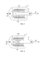
Figure 1 is a cross-sectional view of an embodiment of a safety connector in an engaged configuration; -
Figure 2 is an enlarged view of a portion of the safety connector; -
Figure 3 is a cross-sectional view of the safety connector following an impact, wherein the safety connector is in an engaged configuration and is shown prior to a maximum displacement of the safety connector from its initial position; -
Figure 4 is a cross-sectional view of the safety connector after the maximum displacement of the safety connector from its initial position; and -
Figure 5 is a cross-sectional view of the safety connector where the amplitude of the impact has decayed below a threshold force such that the safety connector is again in the engaged configuration. - With reference to
Figure 1 , a safety connector 2 according to an embodiment of the invention comprises afirst member 4 and asecond member 6 which are movably coupled to one another. - The
first member 4 comprises a generally cuboid-shaped body portion 7. Thebody portion 7 has anopening 8 at a first end 9a which passes through thebody portion 7 and into acavity 10 inside thefirst member 4. Aninner wall 11 of thecavity 10 provides adisplacement stop 12a at the first end 9a and a displacement stop 12b at asecond end 9b of thecavity 10. - A retention mechanism is provided within the
cavity 10. The retention mechanism comprises a firstelongate retaining portion 14a and a secondelongate retaining portion 14b. Each of the first and second retainingportions displacement stop 12a towards thedisplacement stop 12b at thesecond end 9b of thecavity 10. The first and second retainingportions - Each of the first and second retaining
portions body portion 7 by a plurality ofbeam springs 16. Thebeam springs 16 are flat strips of resilient material, which connect at one end to thebody portion 7 and at the other end to the first or second retainingportion portions body portion 7. The beam springs 16 are configured so that, at rest (i.e. with no applied force), the beam springs are inclined towards a direction substantially perpendicular to the first andsecond retaining portions body portion 7. That is to say the first and second retaining portions are displaced away from theopening 8 so that the beam springs 16 are angled towards thedisplacement stop 12b at thesecond end 9b of thecavity 10. For example, the beam springs will lie at an angle of substantially about 30 to 45 degrees to a direction perpendicular to the first andsecond retaining portions body portion 7. The beam springs 16 bias the first andsecond retaining portions second retaining portions opening 8 of thebody portion 7 and a component that acts to force the first andsecond retaining portions - As shown particularly in
Figure 2 , each of the first andsecond retaining portions surface 18 which opposes the other of the first andsecond retaining portions indentations 20 spaced along the inward facingsurface 18. Theindentations 20 are separated from one another byplanar regions 22. Each of theindentations 20 is defined by aforward facing surface 24 which is angled towards theopening 8 at the first end 9a of thebody portion 7 and a rearward facingsurface 26 which is angled towards thedisplacement stop 12b at thesecond end 9b of thebody portion 7. - The
second member 6 is an elongate member which comprises arod portion 28 and ahead portion 30 coupled to an end of therod portion 28. Thehead portion 30 is slightly wider than therod portion 28 and has a pair ofshoulders 32 where thehead portion 30 joins therod portion 28. Thehead portion 30 has anend surface 38 at an opposite end to therod portion 28. Thehead portion 30 comprises a first outward facing surface 34a and a second outward facing surface 34b. The first and second outward facing surfaces 34a, 34b each comprise a plurality ofprotrusions 36 which are spaced along the outward facing surfaces 34a, 34b and which form a saw-tooth arrangement. Each of theprotrusions 36 is defined by aforward facing surface 40 which is angled towards a free end of thehead portion 30 and a rearward facingsurface 42 which is angled towards therod portion 28 of thesecond member 6. - The
first member 4 is provided with a through bore comprising anattachment point 44a and thesecond member 6 is provided with a through bore comprising an attachment point 44b. In use, theattachment point 44a of thefirst member 4 is connected to a piece of ancillary equipment (not shown), for example by means of a bolt, and the attachment point 44b of thesecond member 6 is connected to a fan case of a gas turbine engine (also not shown), for example by means of a bolt, or vice versa. The safety connector 2 therefore connects the ancillary equipment to the fan case. - In an assembled condition of the safety connector 2, the
head portion 30 of thesecond member 6 is received into thecavity 10 of thefirst member 4 with therod portion 28 extending through theopening 8. Thehead portion 30 is disposed between the first andsecond retaining portions second retaining portions head portion 30. - As described previously, the first and
second retaining portions head portion 30 between the first andsecond retaining portions second retaining portions - The
protrusions 36 of thehead portion 30 are complementary to theindentations 20 of the first andsecond retaining portions protrusions 36 interlock with theindentations 20, with the forward facing surfaces 40 of theprotrusions 36 contacting the rearward facingsurfaces 26 of theindentations 20 and the rearward facingsurfaces 42 of theprotrusions 30 contacting the forward facing surfaces 24 of theindentations 20. - The beam springs 16 force the first and
second retaining portions protrusions 36 of thehead portion 30 being withdrawn from theindentations 20. In order to overcome the biasing force applied by the beam springs 16 it is necessary to exert a force between thefirst member 4 and thesecond member 6 which exceeds a predetermined threshold force. This force may act to push thehead portion 30 inwards (i.e. towards thedisplacement stop 12b) or to pull thehead portion 30 outwards (i.e. towards thedisplacement stop 12a), as shown byarrows second retaining portions - Where the
head portion 30 is forced inwards, the forward facing surfaces 24 of theindentations 20 ride up the rearward facingsurfaces 42 of theprotrusions 36. Alternatively, where thehead portion 30 is forced outwards, the rearward facingsurfaces 26 of theindentations 20 ride up the forward facing surfaces 40 of theprotrusions 36. The angles of theprotrusions 36 andindentations 20 are configured so as to provide substantially identical threshold forces for overcoming the biasing force in both the inward andoutward directions - Once the
protrusions 36 have been withdrawn from theindentations 20 they ride along theplanar regions 22 of the inward facing surfaces 18 allowing relative movement between the first andsecond members protrusions 36 may rest on theplanar regions 22 without exerting any force between thefirst member 4 and thesecond member 6. Furthermore, theprotrusions 36 may move over theplanar regions 22 even if the exerted force is below the predetermined threshold force. - The
second member 6 may be displaced so that eachprotrusion 36 moves to thenext indentation 20 along the length of the inward facing surfaces 18. If the force is below the predetermined threshold force, the beam springs force the first andsecond retaining portions protrusions 36 into theindentations 20. However, if the force is above the predetermined threshold force the retainingportions protrusions 36 to continue to the nextplanar regions 22. This may continue until theshoulders 32 of the head portion contact thedisplacement stop 12a or theend surface 38 contacts thedisplacement stop 12b. - Accordingly, the safety connector 2 may be used to isolate the ancillary equipment from movement of the fan case, and vice versa.
- As described previously, a blade-off event can create a travelling wave to form around the fan case periphery which can cause damage to any ancillary equipment connected to it. As shown in
Figure 3 , the travelling wave initially causes the fan case to move outwards, as indicated by thearrow 46. The inertia of the ancillary equipment provides resistance to this force, as indicated byarrow 50, and therefore a force is exerted between thefirst member 4 and thesecond member 6. When this force exceeds the predetermined threshold force and therefore thefirst member 4 andsecond member 6 are displaced relative to one another, thehead portion 30 moves further within thecavity 10 towards thedisplacement stop 12b. The displacement of thesecond member 6 requires work to be done in order to overcome the biasing force of the beam springs 16. Accordingly, the energy of the travelling wave is dissipated by the damping action of the safety connector 2. Preferably, the travelling wave reaches its maximum amplitude before theend surface 38 of thehead portion 30 contacts thedisplacement stop 12b, as shown inFigure 3 . - After the travelling wave has reached its maximum amplitude, the fan case moves back towards its initial position, as indicated by
arrow 48 inFigure 3 . Again, the inertia of the ancillary equipment provides resistance to this force, as indicated byarrow 52, and therefore a force is exerted between thefirst member 4 and thesecond member 6 which exceeds the predetermined threshold force. Consequently, thefirst member 4 andsecond member 6 are displaced relative to one another so that thehead portion 30 is withdrawn from thecavity 10 towards thedisplacement stop 12a. - This cycle is repeated until the travelling wave has decayed sufficiently so that the force between the first and
second members Figure 4 , when the force is below this force theprotrusions 36 engage with theindentations 20 so as to lock the first andsecond members second members - Although the embodiment described above employs beam springs 16 to bias the first and
second retaining portions second retaining portions second retaining portions body portion 7. Further still, an elastomeric or hydraulic element or other resilient member may be located between each of the first andsecond retaining portions body portion 7, or the first andsecond training portions first member 4 when the predetermined threshold force is exceeded. - The first and
second members points 44a, 44b. - Although the safety connector 2 described above allowed linear movement between the first and
second members second member 6 about thefirst member 4 in both clockwise and anticlockwise directions. - The
indentations 20 of the first andsecond retaining portions head portion 30 may comprise asingle protrusion 36 to be received in theindentations 20. - Furthermore, the angles of the forward and rearward facing
surfaces indentations 20 and the forward and rearward facingsurfaces protrusions 36 may be selected so as to define the threshold force required to overcome the biasing force. - Although the safety connector 2 has been described as connecting ancillary equipment to a fan case, it could be used for various other applications. For example, the safety connector 2 may be used to connect other elements of a gas turbine engine to one another where it is desired to isolate each component from movement of the other component.
- Furthermore, the invention may be used to provide a resettable crumple zone for an automobile. For example, a plurality of safety connectors 2 may be used to connect a bumper of an automobile to its chassis. In the event of a collision, the first and
second members second members - The invention may also be employed as a lifting failsafe device. Here, the safety connector 2 is incorporated into a lift system by being placed between the hook and the hoist. The predetermined threshold force for the safety connector 2 may be designed to be equal to the Safe working Load (SWL) of the lifting system. Accordingly, should the SWL of the lifting system be exceeded then the first and
second members end surface 38 or theshoulders 32 of thehead portion 30.
Claims (15)
- A safety connector comprising:a first member and a second member movably coupled to one another;wherein the first and/or second members comprise a retention mechanism;wherein the retention mechanism has a first configuration which prevents relative movement between the first and second members and a second configuration which allows relative movement between the first and second members; andwherein the retention mechanism changes from the first configuration to the second configuration when a force between the first and second members exceeds a predetermined threshold force.
- A safety connector as claimed in claim 1, wherein the first and second members are translatably coupled to one another.
- A safety connector as claimed in claim 1, wherein the first and second members are rotatably coupled to another.
- A safety connector as claimed in claim 2 or 3, wherein the first and second members are coupled so as to allow movement in two directions.
- A safety connector as claimed in any of the preceding claims, wherein the first member comprises a body portion having a cavity therein for receiving the second member.
- A safety connector as claimed in any of the preceding claims, wherein the retention mechanism is operable to dampen movement between the first and second members.
- A safety connector as claimed in any of the preceding claims, wherein the retention mechanism comprises a biasing arrangement which biases a part of the retention mechanism towards the first configuration.
- A safety connector as claimed in claim 7, wherein the biasing arrangement comprises a plurality of beam-springs.
- A safety connector as claimed in any of the preceding claims, wherein the first and second members comprise complementary features which interlock in the first configuration.
- A safety connector as claimed in claim 9, wherein the first member comprises an indentation and the second member comprises a protrusion which interlocks with one another in the first configuration.
- A safety connector as claimed in claim 10, wherein the first member comprises a plurality of indentations and the second member comprises a plurality of protrusions which interlock with one another.
- A safety connector as claimed in claim 10 or 11, wherein the or each indentation and protrusion has a pair of surfaces which define the indentation or protrusion, and wherein the angle of these surfaces is selected to determine the predetermined threshold force
- A safety connector as claimed in any of the preceding claims, wherein the first and/or second members comprise one or more displacement stops which limit the range of movement of the first and second members.
- A safety connector as claimed in any of the preceding claims, wherein the first and second members are connected to or integrally formed with first and second components respectively, and the safety connector isolates the first component from movement of the second component and vice versa.
- A safety connector as claimed in claim 14, wherein the first component is a fan-case of a gas turbine engine and the second component is an ancillary component of the engine which is attached to the fan case.
Applications Claiming Priority (1)
| Application Number | Priority Date | Filing Date | Title |
|---|---|---|---|
| GB1103518.5A GB2488975B (en) | 2011-03-02 | 2011-03-02 | A safety connector |
Publications (3)
| Publication Number | Publication Date |
|---|---|
| EP2495452A2 true EP2495452A2 (en) | 2012-09-05 |
| EP2495452A3 EP2495452A3 (en) | 2013-08-28 |
| EP2495452B1 EP2495452B1 (en) | 2014-07-16 |
Family
ID=43904400
Family Applications (1)
| Application Number | Title | Priority Date | Filing Date |
|---|---|---|---|
| EP12153698.1A Not-in-force EP2495452B1 (en) | 2011-03-02 | 2012-02-02 | A safety connector |
Country Status (3)
| Country | Link |
|---|---|
| US (1) | US8943656B2 (en) |
| EP (1) | EP2495452B1 (en) |
| GB (1) | GB2488975B (en) |
Families Citing this family (1)
| Publication number | Priority date | Publication date | Assignee | Title |
|---|---|---|---|---|
| DE102015225107A1 (en) | 2015-12-14 | 2017-06-14 | Rolls-Royce Deutschland Ltd & Co Kg | Gas turbine combustion chamber with shingle fastening by means of locking elements |
Family Cites Families (5)
| Publication number | Priority date | Publication date | Assignee | Title |
|---|---|---|---|---|
| US2495667A (en) * | 1947-02-07 | 1950-01-24 | Ornstein & Sons Corp D | Adjustable clasp |
| US3741514A (en) * | 1972-04-17 | 1973-06-26 | G Snurr | Quick adjustable height support |
| US6345946B1 (en) * | 2000-08-03 | 2002-02-12 | Radio Systems Corporation | Fastener |
| FR2817925B1 (en) | 2000-12-11 | 2003-09-19 | Renault | ATTACHMENT OF ONE PART TO ANOTHER, WITH POSITIONING IN THE THREE AXES, IN PARTICULAR FOR A VEHICLE COVERING PART |
| EP1590573A2 (en) * | 2003-01-30 | 2005-11-02 | Fraunhofer-Gesellschaft Zur Förderung Der Angewandten Forschung E.V. | Connection element and method for the production of composite constructions from metallic support structures and plastic plankings, comprising tolerance compensation on two planes |
-
2011
- 2011-03-02 GB GB1103518.5A patent/GB2488975B/en not_active Expired - Fee Related
-
2012
- 2012-02-02 EP EP12153698.1A patent/EP2495452B1/en not_active Not-in-force
- 2012-02-02 US US13/364,690 patent/US8943656B2/en active Active
Non-Patent Citations (1)
| Title |
|---|
| None |
Also Published As
| Publication number | Publication date |
|---|---|
| US8943656B2 (en) | 2015-02-03 |
| US20120222274A1 (en) | 2012-09-06 |
| GB2488975A (en) | 2012-09-19 |
| GB201103518D0 (en) | 2011-04-13 |
| GB2488975B (en) | 2014-02-26 |
| EP2495452A3 (en) | 2013-08-28 |
| EP2495452B1 (en) | 2014-07-16 |
Similar Documents
| Publication | Publication Date | Title |
|---|---|---|
| EP3856631B1 (en) | Uav with protective outer cage | |
| EP2325522A1 (en) | Shock-isolation structure | |
| US20180274618A1 (en) | Bi-linear energy dissipating and shock absorbing device for cable subjected to tension | |
| DE102011078376A1 (en) | Handle device, in particular for hand tools | |
| DE102013014333A1 (en) | Mechanical stopper device with an elastically deformable body with slit and multi-jointed robot with the stopper device | |
| DE102012104601A1 (en) | Microelectromechanical system acceleration sensor e.g. linear acceleration sensor, has stoppers, where distance of contact region from x-axis is different from distance of another region such that torque acts on sensor mass | |
| EP2221501A2 (en) | Shock damper | |
| US8943656B2 (en) | Safety connector | |
| JP4881958B2 (en) | Container locking device | |
| DE102016106689A1 (en) | attenuator | |
| US11261945B1 (en) | Coupling system for reducing fatigue and dynamic amplification of loads in objects | |
| JP5925514B2 (en) | Laminated rubber structure | |
| US8272598B2 (en) | Load disconnection lock | |
| US20160258199A1 (en) | Spring and/or damping element | |
| CA2674517C (en) | Load disconnection lock | |
| US11286021B2 (en) | Sensor fastener arrangement | |
| JP6411297B2 (en) | Damping damper | |
| US10358060B1 (en) | Torsionally deforming energy attenuator | |
| EP3631781A1 (en) | Device for making the electrical movements of moving platforms for simulators safer | |
| US20130015613A1 (en) | Energy absorbing elements | |
| EP4464186A1 (en) | Helmet with combiner | |
| EP2874871B1 (en) | Device for mounting a marine engine on an engine pedestal | |
| Smith | 62047 Mitigation of Bolted Single Mass Secondary Projectiles Induced by Direct Surface Impact (Miscellaneous Applications) | |
| DE102017105519B4 (en) | Missile approach warning system | |
| KR101341410B1 (en) | Device for reducing head injury criterion during collision of human body |
Legal Events
| Date | Code | Title | Description |
|---|---|---|---|
| PUAI | Public reference made under article 153(3) epc to a published international application that has entered the european phase |
Free format text: ORIGINAL CODE: 0009012 |
|
| AK | Designated contracting states |
Kind code of ref document: A2 Designated state(s): AL AT BE BG CH CY CZ DE DK EE ES FI FR GB GR HR HU IE IS IT LI LT LU LV MC MK MT NL NO PL PT RO RS SE SI SK SM TR |
|
| AX | Request for extension of the european patent |
Extension state: BA ME |
|
| PUAL | Search report despatched |
Free format text: ORIGINAL CODE: 0009013 |
|
| AK | Designated contracting states |
Kind code of ref document: A3 Designated state(s): AL AT BE BG CH CY CZ DE DK EE ES FI FR GB GR HR HU IE IS IT LI LT LU LV MC MK MT NL NO PL PT RO RS SE SI SK SM TR |
|
| AX | Request for extension of the european patent |
Extension state: BA ME |
|
| RIC1 | Information provided on ipc code assigned before grant |
Ipc: F16B 2/18 20060101AFI20130723BHEP |
|
| 17P | Request for examination filed |
Effective date: 20140218 |
|
| RBV | Designated contracting states (corrected) |
Designated state(s): AL AT BE BG CH CY CZ DE DK EE ES FI FR GB GR HR HU IE IS IT LI LT LU LV MC MK MT NL NO PL PT RO RS SE SI SK SM TR |
|
| GRAP | Despatch of communication of intention to grant a patent |
Free format text: ORIGINAL CODE: EPIDOSNIGR1 |
|
| GRAS | Grant fee paid |
Free format text: ORIGINAL CODE: EPIDOSNIGR3 |
|
| INTG | Intention to grant announced |
Effective date: 20140516 |
|
| GRAA | (expected) grant |
Free format text: ORIGINAL CODE: 0009210 |
|
| AK | Designated contracting states |
Kind code of ref document: B1 Designated state(s): AL AT BE BG CH CY CZ DE DK EE ES FI FR GB GR HR HU IE IS IT LI LT LU LV MC MK MT NL NO PL PT RO RS SE SI SK SM TR |
|
| REG | Reference to a national code |
Ref country code: GB Ref legal event code: FG4D |
|
| REG | Reference to a national code |
Ref country code: CH Ref legal event code: EP |
|
| REG | Reference to a national code |
Ref country code: IE Ref legal event code: FG4D |
|
| REG | Reference to a national code |
Ref country code: AT Ref legal event code: REF Ref document number: 677839 Country of ref document: AT Kind code of ref document: T Effective date: 20140815 |
|
| REG | Reference to a national code |
Ref country code: DE Ref legal event code: R096 Ref document number: 602012002384 Country of ref document: DE Effective date: 20140828 |
|
| REG | Reference to a national code |
Ref country code: NL Ref legal event code: VDEP Effective date: 20140716 |
|
| REG | Reference to a national code |
Ref country code: AT Ref legal event code: MK05 Ref document number: 677839 Country of ref document: AT Kind code of ref document: T Effective date: 20140716 |
|
| REG | Reference to a national code |
Ref country code: LT Ref legal event code: MG4D |
|
| PG25 | Lapsed in a contracting state [announced via postgrant information from national office to epo] |
Ref country code: NO Free format text: LAPSE BECAUSE OF FAILURE TO SUBMIT A TRANSLATION OF THE DESCRIPTION OR TO PAY THE FEE WITHIN THE PRESCRIBED TIME-LIMIT Effective date: 20141016 Ref country code: GR Free format text: LAPSE BECAUSE OF FAILURE TO SUBMIT A TRANSLATION OF THE DESCRIPTION OR TO PAY THE FEE WITHIN THE PRESCRIBED TIME-LIMIT Effective date: 20141017 Ref country code: ES Free format text: LAPSE BECAUSE OF FAILURE TO SUBMIT A TRANSLATION OF THE DESCRIPTION OR TO PAY THE FEE WITHIN THE PRESCRIBED TIME-LIMIT Effective date: 20140716 Ref country code: BG Free format text: LAPSE BECAUSE OF FAILURE TO SUBMIT A TRANSLATION OF THE DESCRIPTION OR TO PAY THE FEE WITHIN THE PRESCRIBED TIME-LIMIT Effective date: 20141016 Ref country code: SE Free format text: LAPSE BECAUSE OF FAILURE TO SUBMIT A TRANSLATION OF THE DESCRIPTION OR TO PAY THE FEE WITHIN THE PRESCRIBED TIME-LIMIT Effective date: 20140716 Ref country code: LT Free format text: LAPSE BECAUSE OF FAILURE TO SUBMIT A TRANSLATION OF THE DESCRIPTION OR TO PAY THE FEE WITHIN THE PRESCRIBED TIME-LIMIT Effective date: 20140716 Ref country code: PT Free format text: LAPSE BECAUSE OF FAILURE TO SUBMIT A TRANSLATION OF THE DESCRIPTION OR TO PAY THE FEE WITHIN THE PRESCRIBED TIME-LIMIT Effective date: 20141117 Ref country code: FI Free format text: LAPSE BECAUSE OF FAILURE TO SUBMIT A TRANSLATION OF THE DESCRIPTION OR TO PAY THE FEE WITHIN THE PRESCRIBED TIME-LIMIT Effective date: 20140716 |
|
| PG25 | Lapsed in a contracting state [announced via postgrant information from national office to epo] |
Ref country code: LV Free format text: LAPSE BECAUSE OF FAILURE TO SUBMIT A TRANSLATION OF THE DESCRIPTION OR TO PAY THE FEE WITHIN THE PRESCRIBED TIME-LIMIT Effective date: 20140716 Ref country code: PL Free format text: LAPSE BECAUSE OF FAILURE TO SUBMIT A TRANSLATION OF THE DESCRIPTION OR TO PAY THE FEE WITHIN THE PRESCRIBED TIME-LIMIT Effective date: 20140716 Ref country code: NL Free format text: LAPSE BECAUSE OF FAILURE TO SUBMIT A TRANSLATION OF THE DESCRIPTION OR TO PAY THE FEE WITHIN THE PRESCRIBED TIME-LIMIT Effective date: 20140716 Ref country code: CY Free format text: LAPSE BECAUSE OF FAILURE TO SUBMIT A TRANSLATION OF THE DESCRIPTION OR TO PAY THE FEE WITHIN THE PRESCRIBED TIME-LIMIT Effective date: 20140716 Ref country code: RS Free format text: LAPSE BECAUSE OF FAILURE TO SUBMIT A TRANSLATION OF THE DESCRIPTION OR TO PAY THE FEE WITHIN THE PRESCRIBED TIME-LIMIT Effective date: 20140716 Ref country code: AT Free format text: LAPSE BECAUSE OF FAILURE TO SUBMIT A TRANSLATION OF THE DESCRIPTION OR TO PAY THE FEE WITHIN THE PRESCRIBED TIME-LIMIT Effective date: 20140716 Ref country code: IS Free format text: LAPSE BECAUSE OF FAILURE TO SUBMIT A TRANSLATION OF THE DESCRIPTION OR TO PAY THE FEE WITHIN THE PRESCRIBED TIME-LIMIT Effective date: 20141116 |
|
| REG | Reference to a national code |
Ref country code: DE Ref legal event code: R097 Ref document number: 602012002384 Country of ref document: DE |
|
| PG25 | Lapsed in a contracting state [announced via postgrant information from national office to epo] |
Ref country code: RO Free format text: LAPSE BECAUSE OF FAILURE TO SUBMIT A TRANSLATION OF THE DESCRIPTION OR TO PAY THE FEE WITHIN THE PRESCRIBED TIME-LIMIT Effective date: 20140716 Ref country code: CZ Free format text: LAPSE BECAUSE OF FAILURE TO SUBMIT A TRANSLATION OF THE DESCRIPTION OR TO PAY THE FEE WITHIN THE PRESCRIBED TIME-LIMIT Effective date: 20140716 Ref country code: DK Free format text: LAPSE BECAUSE OF FAILURE TO SUBMIT A TRANSLATION OF THE DESCRIPTION OR TO PAY THE FEE WITHIN THE PRESCRIBED TIME-LIMIT Effective date: 20140716 Ref country code: IT Free format text: LAPSE BECAUSE OF FAILURE TO SUBMIT A TRANSLATION OF THE DESCRIPTION OR TO PAY THE FEE WITHIN THE PRESCRIBED TIME-LIMIT Effective date: 20140716 Ref country code: SK Free format text: LAPSE BECAUSE OF FAILURE TO SUBMIT A TRANSLATION OF THE DESCRIPTION OR TO PAY THE FEE WITHIN THE PRESCRIBED TIME-LIMIT Effective date: 20140716 Ref country code: EE Free format text: LAPSE BECAUSE OF FAILURE TO SUBMIT A TRANSLATION OF THE DESCRIPTION OR TO PAY THE FEE WITHIN THE PRESCRIBED TIME-LIMIT Effective date: 20140716 |
|
| PLBE | No opposition filed within time limit |
Free format text: ORIGINAL CODE: 0009261 |
|
| STAA | Information on the status of an ep patent application or granted ep patent |
Free format text: STATUS: NO OPPOSITION FILED WITHIN TIME LIMIT |
|
| 26N | No opposition filed |
Effective date: 20150417 |
|
| PG25 | Lapsed in a contracting state [announced via postgrant information from national office to epo] |
Ref country code: BE Free format text: LAPSE BECAUSE OF NON-PAYMENT OF DUE FEES Effective date: 20150228 |
|
| PG25 | Lapsed in a contracting state [announced via postgrant information from national office to epo] |
Ref country code: LU Free format text: LAPSE BECAUSE OF FAILURE TO SUBMIT A TRANSLATION OF THE DESCRIPTION OR TO PAY THE FEE WITHIN THE PRESCRIBED TIME-LIMIT Effective date: 20150202 |
|
| REG | Reference to a national code |
Ref country code: CH Ref legal event code: PL |
|
| PG25 | Lapsed in a contracting state [announced via postgrant information from national office to epo] |
Ref country code: MC Free format text: LAPSE BECAUSE OF FAILURE TO SUBMIT A TRANSLATION OF THE DESCRIPTION OR TO PAY THE FEE WITHIN THE PRESCRIBED TIME-LIMIT Effective date: 20140716 Ref country code: LI Free format text: LAPSE BECAUSE OF NON-PAYMENT OF DUE FEES Effective date: 20150228 Ref country code: CH Free format text: LAPSE BECAUSE OF NON-PAYMENT OF DUE FEES Effective date: 20150228 |
|
| REG | Reference to a national code |
Ref country code: IE Ref legal event code: MM4A |
|
| PG25 | Lapsed in a contracting state [announced via postgrant information from national office to epo] |
Ref country code: SI Free format text: LAPSE BECAUSE OF FAILURE TO SUBMIT A TRANSLATION OF THE DESCRIPTION OR TO PAY THE FEE WITHIN THE PRESCRIBED TIME-LIMIT Effective date: 20140716 |
|
| PG25 | Lapsed in a contracting state [announced via postgrant information from national office to epo] |
Ref country code: IE Free format text: LAPSE BECAUSE OF NON-PAYMENT OF DUE FEES Effective date: 20150202 |
|
| REG | Reference to a national code |
Ref country code: FR Ref legal event code: PLFP Year of fee payment: 5 |
|
| PG25 | Lapsed in a contracting state [announced via postgrant information from national office to epo] |
Ref country code: BE Free format text: LAPSE BECAUSE OF FAILURE TO SUBMIT A TRANSLATION OF THE DESCRIPTION OR TO PAY THE FEE WITHIN THE PRESCRIBED TIME-LIMIT Effective date: 20140716 |
|
| PG25 | Lapsed in a contracting state [announced via postgrant information from national office to epo] |
Ref country code: MT Free format text: LAPSE BECAUSE OF FAILURE TO SUBMIT A TRANSLATION OF THE DESCRIPTION OR TO PAY THE FEE WITHIN THE PRESCRIBED TIME-LIMIT Effective date: 20140716 |
|
| REG | Reference to a national code |
Ref country code: FR Ref legal event code: PLFP Year of fee payment: 6 |
|
| PG25 | Lapsed in a contracting state [announced via postgrant information from national office to epo] |
Ref country code: SM Free format text: LAPSE BECAUSE OF FAILURE TO SUBMIT A TRANSLATION OF THE DESCRIPTION OR TO PAY THE FEE WITHIN THE PRESCRIBED TIME-LIMIT Effective date: 20140716 Ref country code: HU Free format text: LAPSE BECAUSE OF FAILURE TO SUBMIT A TRANSLATION OF THE DESCRIPTION OR TO PAY THE FEE WITHIN THE PRESCRIBED TIME-LIMIT; INVALID AB INITIO Effective date: 20120202 |
|
| PG25 | Lapsed in a contracting state [announced via postgrant information from national office to epo] |
Ref country code: HR Free format text: LAPSE BECAUSE OF FAILURE TO SUBMIT A TRANSLATION OF THE DESCRIPTION OR TO PAY THE FEE WITHIN THE PRESCRIBED TIME-LIMIT Effective date: 20140716 |
|
| PG25 | Lapsed in a contracting state [announced via postgrant information from national office to epo] |
Ref country code: TR Free format text: LAPSE BECAUSE OF FAILURE TO SUBMIT A TRANSLATION OF THE DESCRIPTION OR TO PAY THE FEE WITHIN THE PRESCRIBED TIME-LIMIT Effective date: 20140716 |
|
| REG | Reference to a national code |
Ref country code: FR Ref legal event code: PLFP Year of fee payment: 7 |
|
| PG25 | Lapsed in a contracting state [announced via postgrant information from national office to epo] |
Ref country code: MK Free format text: LAPSE BECAUSE OF FAILURE TO SUBMIT A TRANSLATION OF THE DESCRIPTION OR TO PAY THE FEE WITHIN THE PRESCRIBED TIME-LIMIT Effective date: 20140716 |
|
| PG25 | Lapsed in a contracting state [announced via postgrant information from national office to epo] |
Ref country code: AL Free format text: LAPSE BECAUSE OF FAILURE TO SUBMIT A TRANSLATION OF THE DESCRIPTION OR TO PAY THE FEE WITHIN THE PRESCRIBED TIME-LIMIT Effective date: 20140716 |
|
| PGFP | Annual fee paid to national office [announced via postgrant information from national office to epo] |
Ref country code: FR Payment date: 20230223 Year of fee payment: 12 |
|
| PGFP | Annual fee paid to national office [announced via postgrant information from national office to epo] |
Ref country code: GB Payment date: 20230214 Year of fee payment: 12 Ref country code: DE Payment date: 20230227 Year of fee payment: 12 |
|
| P01 | Opt-out of the competence of the unified patent court (upc) registered |
Effective date: 20230528 |
|
| REG | Reference to a national code |
Ref country code: DE Ref legal event code: R119 Ref document number: 602012002384 Country of ref document: DE |
|
| GBPC | Gb: european patent ceased through non-payment of renewal fee |
Effective date: 20240202 |
|
| PG25 | Lapsed in a contracting state [announced via postgrant information from national office to epo] |
Ref country code: DE Free format text: LAPSE BECAUSE OF NON-PAYMENT OF DUE FEES Effective date: 20240903 |
|
| PG25 | Lapsed in a contracting state [announced via postgrant information from national office to epo] |
Ref country code: GB Free format text: LAPSE BECAUSE OF NON-PAYMENT OF DUE FEES Effective date: 20240202 |
|
| PG25 | Lapsed in a contracting state [announced via postgrant information from national office to epo] |
Ref country code: FR Free format text: LAPSE BECAUSE OF NON-PAYMENT OF DUE FEES Effective date: 20240229 |
|
| PG25 | Lapsed in a contracting state [announced via postgrant information from national office to epo] |
Ref country code: GB Free format text: LAPSE BECAUSE OF NON-PAYMENT OF DUE FEES Effective date: 20240202 Ref country code: FR Free format text: LAPSE BECAUSE OF NON-PAYMENT OF DUE FEES Effective date: 20240229 Ref country code: DE Free format text: LAPSE BECAUSE OF NON-PAYMENT OF DUE FEES Effective date: 20240903 |