EP2495424A1 - Noise reduction device with chamber - Google Patents
Noise reduction device with chamber Download PDFInfo
- Publication number
- EP2495424A1 EP2495424A1 EP10826774A EP10826774A EP2495424A1 EP 2495424 A1 EP2495424 A1 EP 2495424A1 EP 10826774 A EP10826774 A EP 10826774A EP 10826774 A EP10826774 A EP 10826774A EP 2495424 A1 EP2495424 A1 EP 2495424A1
- Authority
- EP
- European Patent Office
- Prior art keywords
- chamber
- microjet
- flow
- peripheral wall
- pipe
- Prior art date
- Legal status (The legal status is an assumption and is not a legal conclusion. Google has not performed a legal analysis and makes no representation as to the accuracy of the status listed.)
- Granted
Links
Images




Classifications
-
- F—MECHANICAL ENGINEERING; LIGHTING; HEATING; WEAPONS; BLASTING
- F02—COMBUSTION ENGINES; HOT-GAS OR COMBUSTION-PRODUCT ENGINE PLANTS
- F02K—JET-PROPULSION PLANTS
- F02K1/00—Plants characterised by the form or arrangement of the jet pipe or nozzle; Jet pipes or nozzles peculiar thereto
- F02K1/28—Plants characterised by the form or arrangement of the jet pipe or nozzle; Jet pipes or nozzles peculiar thereto using fluid jets to influence the jet flow
- F02K1/34—Plants characterised by the form or arrangement of the jet pipe or nozzle; Jet pipes or nozzles peculiar thereto using fluid jets to influence the jet flow for attenuating noise
-
- F—MECHANICAL ENGINEERING; LIGHTING; HEATING; WEAPONS; BLASTING
- F02—COMBUSTION ENGINES; HOT-GAS OR COMBUSTION-PRODUCT ENGINE PLANTS
- F02C—GAS-TURBINE PLANTS; AIR INTAKES FOR JET-PROPULSION PLANTS; CONTROLLING FUEL SUPPLY IN AIR-BREATHING JET-PROPULSION PLANTS
- F02C6/00—Plural gas-turbine plants; Combinations of gas-turbine plants with other apparatus; Adaptations of gas-turbine plants for special use
- F02C6/04—Gas-turbine plants providing heated or pressurised working fluid for other apparatus, e.g. without mechanical power output
- F02C6/06—Gas-turbine plants providing heated or pressurised working fluid for other apparatus, e.g. without mechanical power output providing compressed gas
- F02C6/08—Gas-turbine plants providing heated or pressurised working fluid for other apparatus, e.g. without mechanical power output providing compressed gas the gas being bled from the gas-turbine compressor
-
- F—MECHANICAL ENGINEERING; LIGHTING; HEATING; WEAPONS; BLASTING
- F02—COMBUSTION ENGINES; HOT-GAS OR COMBUSTION-PRODUCT ENGINE PLANTS
- F02K—JET-PROPULSION PLANTS
- F02K1/00—Plants characterised by the form or arrangement of the jet pipe or nozzle; Jet pipes or nozzles peculiar thereto
- F02K1/38—Introducing air inside the jet
-
- F—MECHANICAL ENGINEERING; LIGHTING; HEATING; WEAPONS; BLASTING
- F02—COMBUSTION ENGINES; HOT-GAS OR COMBUSTION-PRODUCT ENGINE PLANTS
- F02K—JET-PROPULSION PLANTS
- F02K1/00—Plants characterised by the form or arrangement of the jet pipe or nozzle; Jet pipes or nozzles peculiar thereto
- F02K1/44—Nozzles having means, e.g. a shield, reducing sound radiation in a specified direction
-
- F—MECHANICAL ENGINEERING; LIGHTING; HEATING; WEAPONS; BLASTING
- F02—COMBUSTION ENGINES; HOT-GAS OR COMBUSTION-PRODUCT ENGINE PLANTS
- F02K—JET-PROPULSION PLANTS
- F02K1/00—Plants characterised by the form or arrangement of the jet pipe or nozzle; Jet pipes or nozzles peculiar thereto
- F02K1/46—Nozzles having means for adding air to the jet or for augmenting the mixing region between the jet and the ambient air, e.g. for silencing
-
- F—MECHANICAL ENGINEERING; LIGHTING; HEATING; WEAPONS; BLASTING
- F02—COMBUSTION ENGINES; HOT-GAS OR COMBUSTION-PRODUCT ENGINE PLANTS
- F02K—JET-PROPULSION PLANTS
- F02K1/00—Plants characterised by the form or arrangement of the jet pipe or nozzle; Jet pipes or nozzles peculiar thereto
- F02K1/52—Nozzles specially constructed for positioning adjacent to another nozzle or to a fixed member, e.g. fairing
-
- F—MECHANICAL ENGINEERING; LIGHTING; HEATING; WEAPONS; BLASTING
- F05—INDEXING SCHEMES RELATING TO ENGINES OR PUMPS IN VARIOUS SUBCLASSES OF CLASSES F01-F04
- F05D—INDEXING SCHEME FOR ASPECTS RELATING TO NON-POSITIVE-DISPLACEMENT MACHINES OR ENGINES, GAS-TURBINES OR JET-PROPULSION PLANTS
- F05D2220/00—Application
- F05D2220/30—Application in turbines
- F05D2220/32—Application in turbines in gas turbines
- F05D2220/323—Application in turbines in gas turbines for aircraft propulsion, e.g. jet engines
-
- F—MECHANICAL ENGINEERING; LIGHTING; HEATING; WEAPONS; BLASTING
- F05—INDEXING SCHEMES RELATING TO ENGINES OR PUMPS IN VARIOUS SUBCLASSES OF CLASSES F01-F04
- F05D—INDEXING SCHEME FOR ASPECTS RELATING TO NON-POSITIVE-DISPLACEMENT MACHINES OR ENGINES, GAS-TURBINES OR JET-PROPULSION PLANTS
- F05D2260/00—Function
- F05D2260/96—Preventing, counteracting or reducing vibration or noise
Definitions
- the present invention relates to a noise reduction system used for a jet engine of an aircraft.
- Priority is claimed on Japanese Patent Application No. 2009-247780, filed on October 28, 2009 , the contents of which are incorporated herein by reference.
- a jet engine of an aircraft includes a fan to take air therein, a compressor to take in and compress part of the air taken by the fan, a combustor to mix compressed air generated by the compressor with fuel and to combust the mixture, and a turbine to drive the fan and the compressor by using combustion gas from the combustor, which are all arranged in sequence.
- the compressor, combustor and turbine are installed in a main nozzle as a cylindrical partition, and the fan is placed in the upstream side of the main nozzle.
- Most of the air taken by the fan flows through a bypass flow path which is provided between the main nozzle and a casing (an engine nacelle) covering the outer periphery of the main nozzle.
- the air (a bypass flow) which has flowed through the bypass flow path is exhausted so as to surround the outside of a core flow (a jet flow) of the turbine, and thus joins to the jet flow.
- a microjet nozzle is provided at an exhaust side peripheral edge of the main nozzle, and a microjet is injected from the microjet nozzle to the confluence of the jet flow and the bypass flow (e.g., refer to Non-Patent Document 1).
- the microjet nozzle communicates with a fan section or the compressor in the jet engine via pipes which are installed in the periphery of the main nozzle. Part of the compressed air generated by the fan or the compressor is guided through the pipes to the microjet nozzle, and then the compressed air is microjet-injected from the microjet nozzle.
- the microjet properly mixes the jet flow and the bypass flow, and the noise can be reduced.
- Patent Document 1 a system and a method are disclosed to reduce exhaust noise of a jet engine nozzle having projections (Chevron).
- the method disclosed in Patent Document 1 includes the steps of generating a first flow of gas by a jet engine, delivering the first flow through a nozzle having a trailing edge perimeter that includes multiple projections extending in the aft direction, and injecting a second flow of a pressurized fluid into the first flow proximate to the projections.
- Patent Document 2 a device is disclosed to reduce exhaust noise of a jet engine by using an oscillating jet.
- a channel which guides an oscillating flow so as to flow out toward engine exhaust gas is configured as a thin pipe. Accordingly, a pressure loss in the thin channel becomes large, and it is practically difficult to supply sufficient oscillating flow to effectively reduce engine exhaust noise.
- additional devices, a flow control valve, a flow stabilizer and the like have to be attached to the channel which guides the oscillating flow. Accordingly, the number of components which compose a system increases, the structure of the system becomes complicated, and assembling workability deteriorates.
- the present invention was conceived in view of the above-described circumstances, and provides a noise reduction system that can efficiently inject a microjet, avoid damage of a pipe, and prevent displacement of a placement position thereof.
- the invention provides a noise reduction system that makes it possible to prevent additional noise in connection with vibration of a pipe, and to improve assembling workability.
- a noise reduction system with a chamber of the first aspect of the present invention is characterized by including a chamber which is provided at a portion of a supply path connecting a flow path in an upstream side of a combustor in a jet engine to a plurality of microjet nozzles which is provided at an exhaust side peripheral edge of a main nozzle of the jet engine, wherein the supply path is configured to supply part of compressed air in the flow path into the chamber, and the chamber is configured to inject the compressed air through the plurality of the microjet nozzles to a jet flow exhausted from the main nozzle.
- a space from the flow path in the upstream side of the combustor to the microjet nozzle can be set large. Accordingly, the pressure loss by using a conventional pipe can be reduced, the microjet can be injected uniformly in the circumferential direction thereof by uniformly pressurizing the chamber, and it is possible to efficiently reduce noise.
- the chamber is installed instead of the pipe, in response to removal of the pipe, damage to the pipe by heat of the jet engine can be avoided, and the displacement of the placement position thereof can be prevented.
- the structure of the chamber is simple, the chamber can be more easily installed than installing operations of the pipe. Therefore, assembling workability thereof can be improved.
- a noise reduction system with a chamber of the second aspect of the present invention is characterized in that the chamber is provided on an outer peripheral surface of the main nozzle in the vicinity of the microjet nozzles.
- the exposure of the pipe can be reduced at the outer peripheral surface of the main nozzle. Accordingly, a cavity flow can be suppressed in response to removal of the pipe, and additional noise in connection with vibration of the pipe can be avoided.
- the nacelle resistance can be reduced, and thereby it is possible to improve the aerodynamic performance of the jet engine.
- the distance from the chamber to the tip of the microjet nozzle can be set short, and thereby the pressure loss of the compressed air can be more reliably reduced in response to shortening of the distance. Therefore, it is possible to more efficiently inject the microjet.
- a noise reduction system with a chamber of the third aspect of the present invention is characterized in that the chamber includes: an inner peripheral wall which is configured as a portion of an inner periphery of the main nozzle; and an outer peripheral wall which is configured as a portion of an outer periphery of the main nozzle, and is formed so as to cover the inner peripheral wall, and the inner and outer peripheral walls are configured so that the compressed air is taken in a space formed between the inner and outer peripheral walls.
- the outer surface of the main nozzle can be smoothly formed, the cavity flow can be more reliably avoided, and the nacelle resistance can be more reliably reduced. Accordingly, the occurrence of additional noise can be more reliably suppressed.
- the structure of the chamber can be further simplified, and an increase in the size of the main nozzle can be avoided.
- the assembling workability thereof can be further improved.
- a space from the flow path in the upstream side of the combustor to the microjet nozzle can be set large. Accordingly, the pressure loss by using a conventional pipe can be reduced, the microjet can be injected uniformly in the circumferential direction by uniformly pressurizing the chamber, and it is possible for noise to be efficiently reduced.
- the chamber is installed instead of the pipe, in response to removal of the pipe, damage to the pipe by heat of the jet engine can be avoided, and the displacement of the placement position thereof can be prevented.
- the structure of the chamber is simple, the chamber can be more easily installed than installing operations of the pipe. Therefore, the assembling workability thereof can be improved.
- the exposure of the pipe can be reduced at the outer peripheral surface of the main nozzle. Accordingly, the cavity flow can be suppressed in response to removal of the pipe, and the additional noise in connection with vibration of the pipe can be avoided.
- the nacelle resistance can be reduced, and thereby the aerodynamic performance of the jet engine can be improved.
- the distance from the chamber to the tip of the microjet nozzle can be set short, and thus the pressure loss of the compressed air can be more reliably reduced in response to shortening of the distance. Therefore, it is possible to inject the microjet more efficiently.
- FIG. 1 is a schematic cross-sectional drawing showing the outline structure of a jet engine 100 to which a noise reduction system 1 of the present invention is applied.
- the jet engine 100 includes a cylindrical casing 2, a cylindrical partition 3 which is inserted in the casing 2 so that a portion of the cylindrical partition 3 protrudes from an exhaust side peripheral edge (a trailing edge) 2a of the casing 2, a fan 11a, a compressor 4, a combustor 12, and a turbine 13.
- the fan 11a, the compressor 4, the combustor 12, and the turbine 13 are arranged inside the casing 2 in sequence from an upstream side to a downstream side along a central axis C1.
- the noise reduction system 1 is provided in the exhaust side (the right side in FIG. 1 ) of the cylindrical partition 3 in the jet engine 100.
- the inside of the cylindrical partition 3 is configured as a flow path 5 through which a high velocity jet flow X flows.
- a space between the cylindrical partition 3 and the casing 2 is configured as a flow path 6 through which a low velocity bypass flow Y flows.
- the casing 2 and the cylindrical partition 3 in the jet engine 100 have the functions as an engine nacelle forming the external shape of the jet engine 100.
- the casing 2 covers a portion of the outer periphery of the cylindrical partition 3.
- An opening of the casing 2 in the upstream side functions as an air inlet 2A to take air A therein.
- an opening of the casing 2 in the downstream side functions as a bypass flow outlet 2B to exhaust the bypass flow Y.
- the bypass flow Y is air which was not taken in the compressor 4 among the air A taken in from the air inlet 2A, and is a low velocity fluid which flows between the cylindrical partition 3 and the casing 2.
- the jet flow X is a fluid which is exhausted from the turbine 13 and flows inside the cylindrical partition 3.
- the jet flow X is a higher velocity fluid than the bypass flow Y.
- an external air flow Z flows along an outer peripheral surface of the casing 2. In other words, the external air flow Z is a low velocity fluid which flows in the outside of the bypass flow Y.
- the cylindrical partition 3 is placed so as to be slightly displaced toward the downstream side relative to the casing 2 along the central axis C1.
- the cylindrical partition 3 separates the flow path 5 through which the jet flow X flows, from the flow path 6 through which the bypass flow Y flows.
- the fan 11a is installed in the vicinity of the upstream side edge inside the casing 2 and in the upstream side of the cylindrical partition 3.
- the fan 11 a takes the air A therein from the outside.
- the compressor 4 is installed in the downstream side of the fan 11a inside the cylindrical partition 3.
- the compressor 4 takes in and compresses part of the air A taken by the fan 11a.
- the combustor 12 is installed in the downstream side of the compressor 4 inside the cylindrical partition 3.
- the combustor 12 mixes fuel into the air A compressed by the compressor 4, combusts the mixture, and exhausts combustion gas.
- the turbine 13 is installed in the downstream side of the combustor 12 inside the cylindrical partition 3. The turbine 13 drives the fan 11a and the compressor 4 by using the combustion gas exhausted from the combustor 12.
- the casing 2 and the cylindrical partition 3 of the jet engine 100 configured like this are suspended from a wing of an aircraft (not shown), by using a pylon 8 extending toward the downstream side of the jet flow X and the bypass flow Y.
- the pylon 8 includes a projecting portion 8A extending toward the downstream side of the casing 2, and the projecting portion 8A extends in the orthogonal direction to the central axis C1 of the casing 2 and the cylindrical partition 3.
- the cylindrical partition 3 functions as a main nozzle to exhaust the jet flow X, and the noise reduction system 1 is provided on the outer periphery of the cylindrical partition 3.
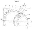
- FIG. 2 is a perspective drawing of the noise reduction system 1.
- FIG. 3 is a cross-sectional drawing along A-A line of FIG. 2 .
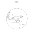
- FIG. 4 is an enlarged drawing in B part of FIG. 3 .
- the noise reduction system 1 includes a chamber 17 which is provided on the outer periphery of the cylindrical partition 3, and a plurality of microjet nozzles 63 which is provided in the downstream side (the right side in FIGS. 1 , 2 ) of the chamber 17 along an exhaust side peripheral edge 3A of the cylindrical partition 3.
- each of the microjet nozzles 63 have the same shape, in FIG. 2 , only one of the microjet nozzles 63 is illustrated and the illustration of the other microjet nozzles 63 is omitted.
- the chamber 17 is formed of stainless steel (e.g., SUS321), inconel alloy or the like, and includes a cylindrical inner peripheral wall 18 which is configured as a portion of the inner periphery of the cylindrical partition 3.
- the inner peripheral wall 18 is formed in a substantially truncated cone shape when viewed from the side thereof, which is gradually reduced in diameter toward the exhaust side (the downstream side).
- the inner diameter of the downstream side edge of the inner peripheral wall 18 is the same as the outer diameter of the upstream side edge in the inner peripheral surface of the cylindrical partition 3.
- An outer flange 18a is integrally formed at the upstream side peripheral edge of the inner peripheral wall 18.
- the outer flange 18a is configured to fix the inner peripheral wall 18 to the cylindrical partition 3, in which a plurality of bolt-holes (not shown) is formed so as to be placed in the circumferential direction thereof at regular intervals.
- a plurality of bolt-holes (not shown) is formed so as to be placed in the circumferential direction thereof at regular intervals.
- female screws are formed at the cylindrical partition 3 at positions corresponding to the bolt-holes. Bolts (not shown) are threaded into the female screws from the inner peripheral wall 18 side, and thereby the inner peripheral wall 18 can be fastened to the cylindrical partition 3.
- a plurality of air inlets 19 is formed at the outer flange 18a at different positions from the bolt-holes (not shown) so as to be placed in the circumferential direction at regular intervals.
- the air inlets 19 are connected to the flow path 5 in the upstream side of the combustor 12 via supply paths 20 which are provided in the cylindrical partition 3.
- One end of the supply path 20 is connected to the air inlet 19 of the outer flange 18a by using a joint (not shown). Accordingly, part of the air A compressed by a fan section 11 or the compressor 4 is taken in the chamber 17.
- a valve 21 is provided on a portion of the supply path 20.
- a Teflon (a registered trademark) tube or the like is used for the supply path 20. By using the Teflon (a registered trademark) tube, it is possible to avoid damage to a pipe caused by expansion thereof by heat of the engine, to reduce a pipe friction loss, and to efficiently inject a microjet.
- An outer flange 62 is integrally formed at the downstream side peripheral edge of the inner peripheral wall 18.
- a plurality of through-holes 65 is formed at the outer flange 62 in the circumferential direction at regular intervals, and each of the microjet nozzles 63 is inserted into each of the through-holes 65.
- a cylindrical outer peripheral wall 22 is provided in the outside of the inner peripheral wall 18, and is formed so as to cover the inner peripheral wall 18 in the range from the outer flange 18a to the outer flange 62.
- the outer peripheral wall 22 is formed in a substantially truncated cone shape when viewed from the side thereof, along the extending direction of the inner peripheral wall 18.
- the outer peripheral wall 22 is configured as a portion of the outer periphery of the cylindrical partition 3. In other words, the outer diameter of the upstream side edge in the outer peripheral surface of the outer peripheral wall 22 is the same as the outer diameter of the downstream side edge in the outer peripheral surface of the cylindrical partition 3 (refer to FIG. 1 ).
- the upstream side peripheral edge of the outer peripheral wall 22 is fixed to the outer flange 18a of the inner peripheral wall 18 by means of welding or the like.
- the downstream side peripheral edge of the outer peripheral wall 22 is fixed to the outer flange 62 of the inner peripheral wall 18 by means of welding or the like.
- Part of the air A compressed by the fan 11a or the compressor 4 is taken in a space K that is surrounded by the outer peripheral wall 22 and the inner peripheral wall 18 which are fixed to each other.
- the microjet nozzle 63 attached to the outer flange 62 of the inner peripheral wall 18 is formed by piping.
- the microjet nozzle 63 is formed of a first pipe 63a and a second pipe 63b.
- the first pipe 63a is extended along the outer peripheral surface of the cylindrical partition 3 and along the axial direction.
- the second pipe 63b is extended from the end of the first pipe 63a along the exhaust side peripheral edge 3A of the cylindrical partition 3, and is inclined toward the central axis C1.
- the inclination angle ⁇ of the second pipe 63b is set to be 30-45 degrees relative to the central axis C1, and the air A taken in the chamber 17 can be reliably injected to the jet flow X exhausted from a jet flow outlet 16A.
- the exhaust side peripheral edge 3A of the cylindrical partition 3 is configured so that the second pipe 63b can be disposed at a desired angle, and is formed so as to be gradually reduced in thickness toward the downstream side.
- the cylindrical partition 3 is gradually reduced in diameter toward the downstream side.
- the microjet nozzle 63 is provided at the tip of the cylindrical partition 3, that is, so that the end of the second pipe 63b is placed along the exhaust side peripheral edge 3A of the cylindrical partition 3. Therefore, an injection outlet of the microjet nozzle 63 becomes disposed at a throat SP of the cylindrical partition 3.
- the jet flow X flows through the flow path 5 inside the cylindrical partition 3, and is exhausted from the jet flow outlet 16A.
- the bypass flow Y flows through the flow path 6 between the cylindrical partition 3 and the casing 2, and is exhausted from the bypass flow outlet 2B.
- the valve 21 is opened, and part of the air A which was compressed by the fan 11a or the compressor 4 is taken in the chamber 17.
- the air A in the chamber 17 is increased to a predetermined pressure, and then the air A is microjet-injected to the jet flow X through the microjet nozzle 63.
- FIG. 5 is an explanatory drawing showing the jet flow X and the flow of the air A when microjet-injection is performed.
- the area in the upstream side of the throat SP has high pressure.
- the area in the downstream side of the throat SP has lower pressure than the upstream side. Therefore, the microjet-injection is injected to the low pressure area, and thereby a sufficient flow volume can be secured without excessively increasing the pressure in the chamber 17.
- the microjet-injection is performed from just behind the throat SP toward the downstream side, that is, so that an acute angle is formed between the injection direction from the throat SP and the axial direction.
- a path in which a pressure loss occurs can be mostly limited to the microjet nozzle 63.
- the microjet nozzle 63 can be formed so that the length thereof in the axial direction is as short as possible. Accordingly, the length of the microjet nozzle 63 in which a pressure loss occurs can be set as short as possible, and it is possible to suppress the pressure loss to the minimum.
- FIG. 6 shows a result of verification of a pressure loss reduction effect by installing the chamber 17 in the upstream side of the microjet nozzle 63.
- a part is clipped from the flow path 5 in the upstream side of the combustor 12 through the chamber 17 to the microjet nozzle 63, and the total pressure loss coefficient (%) in the axial position thereof is illustrated.
- the horizontal axis shows the axial position
- the vertical axis shows the total pressure loss coefficient (%).
- the verification shown in FIG. 6 in which the following conditions were used was conducted by numerical analysis of the total pressure loss coefficient in each axial position thereof.
- the inner diameter of the flow path 5 ⁇ 5mm, 32 pipes
- the total pressure loss coefficient sharply increases at the connecting position between the chamber 17 and the microjet nozzle 63, that is, the position where the axial position is 0.1 (m). This is thought to be caused by the increase of the total pressure loss because the microjet nozzle 63 is smaller in cross-section than the chamber 17 having a large cross-section. However, because the microjet nozzle 63 is small in cross-section, even if the total pressure loss sharply increases as shown in FIG. 6 , the increase of the total pressure loss at the microjet nozzle 63 is maintained from about 10% to about 20%. If the chamber 17 is not installed as shown by using a broken line in FIG.
- the total pressure loss sharply increases from the position where the axial position is 0.18 (m) as the connecting position between the flow path 5 and the chamber 17, in the same manner as the increase of the total pressure loss at the position where the axial position is 0.1 (m) shown in FIG. 6 .
- the total pressure loss increases from the position where the axial position is 0.18 (m) in the same manner as the position where the axial position is 0.1 (m)
- the total pressure loss at the outlet of the microjet nozzle 63 will be more than 50 (%).
- the chamber 17 is an essential component to practically perform microjet-injection in an engine for an aircraft.
- the reason for this is because the total pressure loss can be suppressed in response to the chamber cubic content by installing the chamber 17.
- the loss of an extraction pressure from the engine, the extraction pressure to inject the microjet is greatly reduced, and thus a large extraction from the compressor is unnecessary.
- the chamber 17 is configured to be the space formed by the inner peripheral wall 18 and the outer peripheral wall 22, unlike conventional pipes, damage to the path can be avoided even if heat expansion thereof occurs. Therefore, microjet-injection can be stably performed.
- the air A which was microjet-injected comes to the area where the jet flow X and the bypass flow Y which were exhausted are joined to each other, and thus properly mixes both. Accordingly, the noise generated by the confluence of the jet flow X and the bypass flow Y can be reduced.
- the chamber 17 is provided between the microjet nozzle 63 and the compressor 4, the air A compressed by the fan 11a or the compressor 4, that is, the compressed air in the flow path 5 in the upstream side of the combustor 12, is supplied into the chamber 17, and the microjet-injection is performed from the chamber 17 through the microjet nozzle 63. Accordingly, the pressure loss by the pipe which has previously occurred can be reduced. Therefore, the microjet can be efficiently injected.
- the chamber 17 is installed instead of the pipe, and thus a part of pipes used from the fan section 11 or the compressor 4 to the microjet nozzle 63 can be removed.
- the microjet nozzle 63 or the chamber 17 can suppress the risk of damage thereof due to heat expansion to a lower level than a conventional pipe, and thereby the pressure leak due to pipe damage can be avoided. Moreover, by using the chamber 17, there is no possibility that the path position of the air A is displaced, and thus the microjet-injection can be stably performed.
- the chamber 17 is formed by the cylindrical inner peripheral wall 18 which is configured as a portion of the inner periphery of the cylindrical partition 3, and the outer peripheral wall 22 which is formed so as to cover the inner peripheral wall 18.
- Part of the air A which was compressed by the fan 11a or the compressor 4 is taken in the space K which is surrounded by the inner and outer peripheral walls 18, 22.
- the structure of the chamber 17 can be simplified, and an increase in size of the cylindrical partition 3 can be avoided.
- the assembling operations thereof can be finished. Therefore, the assembling workability can be further improved compared with installation operations of conventional pipes.
- the outer peripheral wall 22 of the chamber 17 becomes configured as the periphery of the cylindrical partition 3, pipes and the like are not exposed to the outside, the cavity flow can be avoided, and additional noise in connection with the cavity flow can be prevented. Further, nacelle resistance of the jet engine 100 can be reduced, and the aerodynamic performance thereof can be improved.
- a noise reduction system with a chamber of the present invention can efficiently inject a microjet, avoid damage of a pipe, and prevent displacement of a placement position thereof.
- a noise reduction system with a chamber of the present invention makes it possible to avoid additional noise in connection with vibration of a pipe, and to improve assembling workability.
Landscapes
- Engineering & Computer Science (AREA)
- Chemical & Material Sciences (AREA)
- Combustion & Propulsion (AREA)
- Mechanical Engineering (AREA)
- General Engineering & Computer Science (AREA)
- Jet Pumps And Other Pumps (AREA)
- Structures Of Non-Positive Displacement Pumps (AREA)
Abstract
Description
- The present invention relates to a noise reduction system used for a jet engine of an aircraft.
Priority is claimed on Japanese Patent Application No.2009-247780, filed on October 28, 2009 - A jet engine of an aircraft includes a fan to take air therein, a compressor to take in and compress part of the air taken by the fan, a combustor to mix compressed air generated by the compressor with fuel and to combust the mixture, and a turbine to drive the fan and the compressor by using combustion gas from the combustor, which are all arranged in sequence.
The compressor, combustor and turbine are installed in a main nozzle as a cylindrical partition, and the fan is placed in the upstream side of the main nozzle. Most of the air taken by the fan flows through a bypass flow path which is provided between the main nozzle and a casing (an engine nacelle) covering the outer periphery of the main nozzle. The air (a bypass flow) which has flowed through the bypass flow path is exhausted so as to surround the outside of a core flow (a jet flow) of the turbine, and thus joins to the jet flow. - The area where the jet flow and the bypass flow join to each other becomes a noise source, and thus noise occurs. Various arts are disclosed to reduce such noise.
For example, an art is disclosed in which a microjet nozzle is provided at an exhaust side peripheral edge of the main nozzle, and a microjet is injected from the microjet nozzle to the confluence of the jet flow and the bypass flow (e.g., refer to Non-Patent Document 1). - The microjet nozzle communicates with a fan section or the compressor in the jet engine via pipes which are installed in the periphery of the main nozzle. Part of the compressed air generated by the fan or the compressor is guided through the pipes to the microjet nozzle, and then the compressed air is microjet-injected from the microjet nozzle. By this configuration, the microjet properly mixes the jet flow and the bypass flow, and the noise can be reduced.
- In
Patent Document 1, a system and a method are disclosed to reduce exhaust noise of a jet engine nozzle having projections (Chevron). The method disclosed inPatent Document 1 includes the steps of generating a first flow of gas by a jet engine, delivering the first flow through a nozzle having a trailing edge perimeter that includes multiple projections extending in the aft direction, and injecting a second flow of a pressurized fluid into the first flow proximate to the projections. - In
Patent Document 2, a device is disclosed to reduce exhaust noise of a jet engine by using an oscillating jet. -
- [Patent Document 1] Published Japanese Translation No.
2010-518323 of the PCT - [Patent Document 2] Japanese Patent Application, First Publication No.
2005-195019 -
- [Non-Patent Document 1] Brenton Greska, other four people, The Effects of Microjet Injection On an F404 Jet Engine, AIAA2005-3047, 11th AIAA/CEAS Aeroacoustics Conference (26th AIAA Aeroacoustics Conference), 23-25 May 2005
- However, in the above conventional arts, because the compressed air is guided from the fan section or the compressor to the microjet nozzle through the pipes, it is difficult to perform the microjet-injection due to a pressure loss in each of the pipes. For example, in the
above Patent Document 1, a pressure loss occurs because a velocity difference is caused by a Chevron Nozzle, and thereby it is difficult to perform the microjet-injection efficiently. - In addition, there is a possibility that the pipe guiding the compressed air expands by heat of the jet engine, the pipe is damaged, and the injection position thereof is displaced.
Further, fluid noise occurs in response to a cavity flow around the pipe, or additional noise occurs in connection with vibration of the pipe.
Operations to install the pipes are complicated, and man-hours for assembling are increased.
Moreover, there is also a possibility that a proper noise reduction effect of the microjet is not obtained by dispersion of accuracy when the pipes are installed. - In
Patent Document 2, a channel which guides an oscillating flow so as to flow out toward engine exhaust gas is configured as a thin pipe. Accordingly, a pressure loss in the thin channel becomes large, and it is practically difficult to supply sufficient oscillating flow to effectively reduce engine exhaust noise. In addition, additional devices, a flow control valve, a flow stabilizer and the like, have to be attached to the channel which guides the oscillating flow. Accordingly, the number of components which compose a system increases, the structure of the system becomes complicated, and assembling workability deteriorates. - The present invention was conceived in view of the above-described circumstances, and provides a noise reduction system that can efficiently inject a microjet, avoid damage of a pipe, and prevent displacement of a placement position thereof.
In addition, the invention provides a noise reduction system that makes it possible to prevent additional noise in connection with vibration of a pipe, and to improve assembling workability. - A noise reduction system with a chamber of the first aspect of the present invention is characterized by including a chamber which is provided at a portion of a supply path connecting a flow path in an upstream side of a combustor in a jet engine to a plurality of microjet nozzles which is provided at an exhaust side peripheral edge of a main nozzle of the jet engine, wherein the supply path is configured to supply part of compressed air in the flow path into the chamber, and the chamber is configured to inject the compressed air through the plurality of the microjet nozzles to a jet flow exhausted from the main nozzle.
- By configuring like this, a space from the flow path in the upstream side of the combustor to the microjet nozzle can be set large. Accordingly, the pressure loss by using a conventional pipe can be reduced, the microjet can be injected uniformly in the circumferential direction thereof by uniformly pressurizing the chamber, and it is possible to efficiently reduce noise.
In addition, because the chamber is installed instead of the pipe, in response to removal of the pipe, damage to the pipe by heat of the jet engine can be avoided, and the displacement of the placement position thereof can be prevented.
Further, because the structure of the chamber is simple, the chamber can be more easily installed than installing operations of the pipe. Therefore, assembling workability thereof can be improved. - A noise reduction system with a chamber of the second aspect of the present invention is characterized in that the chamber is provided on an outer peripheral surface of the main nozzle in the vicinity of the microjet nozzles.
- By configuring like this, the exposure of the pipe can be reduced at the outer peripheral surface of the main nozzle. Accordingly, a cavity flow can be suppressed in response to removal of the pipe, and additional noise in connection with vibration of the pipe can be avoided. The nacelle resistance can be reduced, and thereby it is possible to improve the aerodynamic performance of the jet engine.
In addition, the distance from the chamber to the tip of the microjet nozzle can be set short, and thereby the pressure loss of the compressed air can be more reliably reduced in response to shortening of the distance. Therefore, it is possible to more efficiently inject the microjet. - A noise reduction system with a chamber of the third aspect of the present invention is characterized in that the chamber includes: an inner peripheral wall which is configured as a portion of an inner periphery of the main nozzle; and an outer peripheral wall which is configured as a portion of an outer periphery of the main nozzle, and is formed so as to cover the inner peripheral wall, and the inner and outer peripheral walls are configured so that the compressed air is taken in a space formed between the inner and outer peripheral walls.
- By configuring like this, the outer surface of the main nozzle can be smoothly formed, the cavity flow can be more reliably avoided, and the nacelle resistance can be more reliably reduced. Accordingly, the occurrence of additional noise can be more reliably suppressed.
In addition, the structure of the chamber can be further simplified, and an increase in the size of the main nozzle can be avoided. Moreover, the assembling workability thereof can be further improved. - According to the present invention, a space from the flow path in the upstream side of the combustor to the microjet nozzle can be set large. Accordingly, the pressure loss by using a conventional pipe can be reduced, the microjet can be injected uniformly in the circumferential direction by uniformly pressurizing the chamber, and it is possible for noise to be efficiently reduced.
In addition, because the chamber is installed instead of the pipe, in response to removal of the pipe, damage to the pipe by heat of the jet engine can be avoided, and the displacement of the placement position thereof can be prevented.
Further, because the structure of the chamber is simple, the chamber can be more easily installed than installing operations of the pipe. Therefore, the assembling workability thereof can be improved. - In addition, the exposure of the pipe can be reduced at the outer peripheral surface of the main nozzle. Accordingly, the cavity flow can be suppressed in response to removal of the pipe, and the additional noise in connection with vibration of the pipe can be avoided. The nacelle resistance can be reduced, and thereby the aerodynamic performance of the jet engine can be improved.
Further, the distance from the chamber to the tip of the microjet nozzle can be set short, and thus the pressure loss of the compressed air can be more reliably reduced in response to shortening of the distance. Therefore, it is possible to inject the microjet more efficiently. -
- [
FIG. 1] FIG. 1 is a schematic cross-sectional drawing showing the outline structure of a jet engine in an embodiment of the present invention. - [
FIG. 2] FIG. 2 is a perspective drawing of a noise reduction system in the embodiment of the present invention. - [
FIG. 3] FIG. 3 is a cross-sectional drawing along A-A line ofFIG. 2 . - [
FIG. 4] FIG. 4 is an enlarged drawing in B part ofFIG. 3 . - [
FIG. 5] FIG. 5 is an explanatory drawing showing a jet flow and a flow of air in the embodiment of the present invention. - [
FIG. 6] FIG. 6 is a drawing showing a result of verification of a pressure loss reduction effect by a chamber which is provided in the noise reduction system of the present invention. - An embodiment of the present invention is explained based on
FIGS. 1-5 as follows.
FIG. 1 is a schematic cross-sectional drawing showing the outline structure of ajet engine 100 to which anoise reduction system 1 of the present invention is applied.
As shown inFIG. 1 , thejet engine 100 includes acylindrical casing 2, acylindrical partition 3 which is inserted in thecasing 2 so that a portion of thecylindrical partition 3 protrudes from an exhaust side peripheral edge (a trailing edge) 2a of thecasing 2, afan 11a, acompressor 4, acombustor 12, and aturbine 13. Thefan 11a, thecompressor 4, thecombustor 12, and theturbine 13 are arranged inside thecasing 2 in sequence from an upstream side to a downstream side along a central axis C1. In addition, thenoise reduction system 1 is provided in the exhaust side (the right side inFIG. 1 ) of thecylindrical partition 3 in thejet engine 100.
The inside of thecylindrical partition 3 is configured as aflow path 5 through which a high velocity jet flow X flows. A space between thecylindrical partition 3 and thecasing 2 is configured as aflow path 6 through which a low velocity bypass flow Y flows. - The
casing 2 and thecylindrical partition 3 in thejet engine 100 have the functions as an engine nacelle forming the external shape of thejet engine 100. Thecasing 2 covers a portion of the outer periphery of thecylindrical partition 3.
An opening of thecasing 2 in the upstream side functions as anair inlet 2A to take air A therein. On the other hand, an opening of thecasing 2 in the downstream side functions as abypass flow outlet 2B to exhaust the bypass flow Y. - The bypass flow Y is air which was not taken in the
compressor 4 among the air A taken in from theair inlet 2A, and is a low velocity fluid which flows between thecylindrical partition 3 and thecasing 2. The jet flow X is a fluid which is exhausted from theturbine 13 and flows inside thecylindrical partition 3. The jet flow X is a higher velocity fluid than the bypass flow Y. In the outside of thecasing 2, an external air flow Z flows along an outer peripheral surface of thecasing 2. In other words, the external air flow Z is a low velocity fluid which flows in the outside of the bypass flow Y. - The
cylindrical partition 3 is placed so as to be slightly displaced toward the downstream side relative to thecasing 2 along the central axis C1. Thecylindrical partition 3 separates theflow path 5 through which the jet flow X flows, from theflow path 6 through which the bypass flow Y flows.
Thefan 11a is installed in the vicinity of the upstream side edge inside thecasing 2 and in the upstream side of thecylindrical partition 3. Thefan 11 a takes the air A therein from the outside.
Thecompressor 4 is installed in the downstream side of thefan 11a inside thecylindrical partition 3. Thecompressor 4 takes in and compresses part of the air A taken by thefan 11a. - The
combustor 12 is installed in the downstream side of thecompressor 4 inside thecylindrical partition 3. Thecombustor 12 mixes fuel into the air A compressed by thecompressor 4, combusts the mixture, and exhausts combustion gas.
Theturbine 13 is installed in the downstream side of thecombustor 12 inside thecylindrical partition 3. Theturbine 13 drives thefan 11a and thecompressor 4 by using the combustion gas exhausted from thecombustor 12. - The
casing 2 and thecylindrical partition 3 of thejet engine 100 configured like this are suspended from a wing of an aircraft (not shown), by using apylon 8 extending toward the downstream side of the jet flow X and the bypass flow Y.
Thepylon 8 includes a projectingportion 8A extending toward the downstream side of thecasing 2, and the projectingportion 8A extends in the orthogonal direction to the central axis C1 of thecasing 2 and thecylindrical partition 3.
Thecylindrical partition 3 functions as a main nozzle to exhaust the jet flow X, and thenoise reduction system 1 is provided on the outer periphery of thecylindrical partition 3. -
FIG. 2 is a perspective drawing of thenoise reduction system 1.FIG. 3 is a cross-sectional drawing along A-A line ofFIG. 2 .FIG. 4 is an enlarged drawing in B part ofFIG. 3 .
As shown inFIGS. 1-4 , thenoise reduction system 1 includes achamber 17 which is provided on the outer periphery of thecylindrical partition 3, and a plurality ofmicrojet nozzles 63 which is provided in the downstream side (the right side inFIGS. 1 ,2 ) of thechamber 17 along an exhaust sideperipheral edge 3A of thecylindrical partition 3. In addition, because each of themicrojet nozzles 63 have the same shape, inFIG. 2 , only one of themicrojet nozzles 63 is illustrated and the illustration of theother microjet nozzles 63 is omitted. - The
chamber 17 is formed of stainless steel (e.g., SUS321), inconel alloy or the like, and includes a cylindrical innerperipheral wall 18 which is configured as a portion of the inner periphery of thecylindrical partition 3.
In other words, the innerperipheral wall 18 is formed in a substantially truncated cone shape when viewed from the side thereof, which is gradually reduced in diameter toward the exhaust side (the downstream side). The inner diameter of the downstream side edge of the innerperipheral wall 18 is the same as the outer diameter of the upstream side edge in the inner peripheral surface of thecylindrical partition 3.
Anouter flange 18a is integrally formed at the upstream side peripheral edge of the innerperipheral wall 18. Theouter flange 18a is configured to fix the innerperipheral wall 18 to thecylindrical partition 3, in which a plurality of bolt-holes (not shown) is formed so as to be placed in the circumferential direction thereof at regular intervals. On the other hand, female screws are formed at thecylindrical partition 3 at positions corresponding to the bolt-holes. Bolts (not shown) are threaded into the female screws from the innerperipheral wall 18 side, and thereby the innerperipheral wall 18 can be fastened to thecylindrical partition 3. - A plurality of
air inlets 19 is formed at theouter flange 18a at different positions from the bolt-holes (not shown) so as to be placed in the circumferential direction at regular intervals.
The air inlets 19 are connected to theflow path 5 in the upstream side of thecombustor 12 viasupply paths 20 which are provided in thecylindrical partition 3. One end of thesupply path 20 is connected to theair inlet 19 of theouter flange 18a by using a joint (not shown). Accordingly, part of the air A compressed by afan section 11 or thecompressor 4 is taken in thechamber 17. In addition, avalve 21 is provided on a portion of thesupply path 20.
Further, for example, a Teflon (a registered trademark) tube or the like is used for thesupply path 20.
By using the Teflon (a registered trademark) tube, it is possible to avoid damage to a pipe caused by expansion thereof by heat of the engine, to reduce a pipe friction loss, and to efficiently inject a microjet. - An
outer flange 62 is integrally formed at the downstream side peripheral edge of the innerperipheral wall 18. A plurality of through-holes 65 is formed at theouter flange 62 in the circumferential direction at regular intervals, and each of themicrojet nozzles 63 is inserted into each of the through-holes 65. - A cylindrical outer
peripheral wall 22 is provided in the outside of the innerperipheral wall 18, and is formed so as to cover the innerperipheral wall 18 in the range from theouter flange 18a to theouter flange 62. The outerperipheral wall 22 is formed in a substantially truncated cone shape when viewed from the side thereof, along the extending direction of the innerperipheral wall 18. The outerperipheral wall 22 is configured as a portion of the outer periphery of thecylindrical partition 3. In other words, the outer diameter of the upstream side edge in the outer peripheral surface of the outerperipheral wall 22 is the same as the outer diameter of the downstream side edge in the outer peripheral surface of the cylindrical partition 3 (refer toFIG. 1 ).
The upstream side peripheral edge of the outerperipheral wall 22 is fixed to theouter flange 18a of the innerperipheral wall 18 by means of welding or the like. The downstream side peripheral edge of the outerperipheral wall 22 is fixed to theouter flange 62 of the innerperipheral wall 18 by means of welding or the like. Part of the air A compressed by thefan 11a or thecompressor 4 is taken in a space K that is surrounded by the outerperipheral wall 22 and the innerperipheral wall 18 which are fixed to each other. - The
microjet nozzle 63 attached to theouter flange 62 of the innerperipheral wall 18 is formed by piping. Themicrojet nozzle 63 is formed of afirst pipe 63a and asecond pipe 63b. Thefirst pipe 63a is extended along the outer peripheral surface of thecylindrical partition 3 and along the axial direction. Thesecond pipe 63b is extended from the end of thefirst pipe 63a along the exhaust sideperipheral edge 3A of thecylindrical partition 3, and is inclined toward the central axis C1. - Sealing properties are secured at the connecting portion between the
first pipe 63a and theouter flange 62 of thechamber 17 by means of welding or the like.
The inclination angle θ of thesecond pipe 63b is set to be 30-45 degrees relative to the central axis C1, and the air A taken in thechamber 17 can be reliably injected to the jet flow X exhausted from ajet flow outlet 16A. The exhaust sideperipheral edge 3A of thecylindrical partition 3 is configured so that thesecond pipe 63b can be disposed at a desired angle, and is formed so as to be gradually reduced in thickness toward the downstream side. - As minutely shown in
FIG. 4 , thecylindrical partition 3 is gradually reduced in diameter toward the downstream side. Themicrojet nozzle 63 is provided at the tip of thecylindrical partition 3, that is, so that the end of thesecond pipe 63b is placed along the exhaust sideperipheral edge 3A of thecylindrical partition 3. Therefore, an injection outlet of themicrojet nozzle 63 becomes disposed at a throat SP of thecylindrical partition 3. - Functions of the
jet engine 100 and thenoise reduction system 1 are explained as follows.
As shown inFIG. 1 , when an aircraft takes off, at first, thefan 11a is rotated and thereby the air A is taken in from theair inlet 2A. Part of the air A is compressed by thecompressor 4, mixed with fuel at thecombustor 12, and combusted therein.
In theturbine 13, a driving force is generated to drive thefan 11a and thecompressor 4 by using the combustion gas which was exhausted from thecombustor 12. Thereafter, thefan 11a is rotated by the driving force generated by theturbine 13, and thereby the air A is taken in. - According to motions like this, the jet flow X flows through the
flow path 5 inside thecylindrical partition 3, and is exhausted from thejet flow outlet 16A. In addition, the bypass flow Y flows through theflow path 6 between thecylindrical partition 3 and thecasing 2, and is exhausted from thebypass flow outlet 2B. As a result, thrust is obtained and thus the aircraft takes off.
At this time, thevalve 21 is opened, and part of the air A which was compressed by thefan 11a or thecompressor 4 is taken in thechamber 17. The air A in thechamber 17 is increased to a predetermined pressure, and then the air A is microjet-injected to the jet flow X through themicrojet nozzle 63. -
FIG. 5 is an explanatory drawing showing the jet flow X and the flow of the air A when microjet-injection is performed.
InFIG. 5 , with respect to the jet flow X, the area in the upstream side of the throat SP has high pressure. On the other hand, the area in the downstream side of the throat SP has lower pressure than the upstream side. Therefore, the microjet-injection is injected to the low pressure area, and thereby a sufficient flow volume can be secured without excessively increasing the pressure in thechamber 17. The microjet-injection is performed from just behind the throat SP toward the downstream side, that is, so that an acute angle is formed between the injection direction from the throat SP and the axial direction. - Because the pressure in the
chamber 17 is not excessively increased, the Mach number in the path is not too high, and the pressure loss of the air A in thesupply path 20 can be reduced. Further, a path in which a pressure loss occurs can be mostly limited to themicrojet nozzle 63. - In addition, because the
chamber 17 is disposed adjacent to the upstream side of themicrojet nozzle 63, themicrojet nozzle 63 can be formed so that the length thereof in the axial direction is as short as possible. Accordingly, the length of themicrojet nozzle 63 in which a pressure loss occurs can be set as short as possible, and it is possible to suppress the pressure loss to the minimum. - With respect to the
noise reduction system 1 of the embodiment,FIG. 6 shows a result of verification of a pressure loss reduction effect by installing thechamber 17 in the upstream side of themicrojet nozzle 63. In the verification result shown inFIG. 6 , a part is clipped from theflow path 5 in the upstream side of thecombustor 12 through thechamber 17 to themicrojet nozzle 63, and the total pressure loss coefficient (%) in the axial position thereof is illustrated. InFIG. 6 , the horizontal axis shows the axial position, and the vertical axis shows the total pressure loss coefficient (%).
The verification shown inFIG. 6 in which the following conditions were used was conducted by numerical analysis of the total pressure loss coefficient in each axial position thereof.
The inner diameter of the flow path 5: Φ5mm, 32 pipes
The area of the microjet outlet: the inner diameter of the injection pipeΦ3.15 (mm) * sqrt (32 pipes /20 inlets) = Φ3.52.mm - As shown in
FIG. 6 , the total pressure loss coefficient sharply increases at the connecting position between thechamber 17 and themicrojet nozzle 63, that is, the position where the axial position is 0.1 (m). This is thought to be caused by the increase of the total pressure loss because themicrojet nozzle 63 is smaller in cross-section than thechamber 17 having a large cross-section. However, because themicrojet nozzle 63 is small in cross-section, even if the total pressure loss sharply increases as shown inFIG. 6 , the increase of the total pressure loss at themicrojet nozzle 63 is maintained from about 10% to about 20%.
If thechamber 17 is not installed as shown by using a broken line inFIG. 6 , the total pressure loss sharply increases from the position where the axial position is 0.18 (m) as the connecting position between theflow path 5 and thechamber 17, in the same manner as the increase of the total pressure loss at the position where the axial position is 0.1 (m) shown inFIG. 6 . When the total pressure loss increases from the position where the axial position is 0.18 (m) in the same manner as the position where the axial position is 0.1 (m), it is evident that the total pressure loss at the outlet of themicrojet nozzle 63 will be more than 50 (%). - As is evident from the result shown in
FIG. 6 , thechamber 17 is an essential component to practically perform microjet-injection in an engine for an aircraft. The reason for this is because the total pressure loss can be suppressed in response to the chamber cubic content by installing thechamber 17.
In the noise reduction system according to the embodiment, by installing thechamber 17, the loss of an extraction pressure from the engine, the extraction pressure to inject the microjet, is greatly reduced, and thus a large extraction from the compressor is unnecessary. - Further, when the temperature of each part of the
jet engine 100 increases by the driving thereof, because thechamber 17 is configured to be the space formed by the innerperipheral wall 18 and the outerperipheral wall 22, unlike conventional pipes, damage to the path can be avoided even if heat expansion thereof occurs. Therefore, microjet-injection can be stably performed.
The air A which was microjet-injected comes to the area where the jet flow X and the bypass flow Y which were exhausted are joined to each other, and thus properly mixes both. Accordingly, the noise generated by the confluence of the jet flow X and the bypass flow Y can be reduced. - According to the above embodiment, the
chamber 17 is provided between themicrojet nozzle 63 and thecompressor 4, the air A compressed by thefan 11a or thecompressor 4, that is, the compressed air in theflow path 5 in the upstream side of thecombustor 12, is supplied into thechamber 17, and the microjet-injection is performed from thechamber 17 through themicrojet nozzle 63. Accordingly, the pressure loss by the pipe which has previously occurred can be reduced. Therefore, the microjet can be efficiently injected.
In addition, thechamber 17 is installed instead of the pipe, and thus a part of pipes used from thefan section 11 or thecompressor 4 to themicrojet nozzle 63 can be removed. Themicrojet nozzle 63 or thechamber 17 can suppress the risk of damage thereof due to heat expansion to a lower level than a conventional pipe, and thereby the pressure leak due to pipe damage can be avoided. Moreover, by using thechamber 17, there is no possibility that the path position of the air A is displaced, and thus the microjet-injection can be stably performed. - Further, the
chamber 17 is formed by the cylindrical innerperipheral wall 18 which is configured as a portion of the inner periphery of thecylindrical partition 3, and the outerperipheral wall 22 which is formed so as to cover the innerperipheral wall 18. Part of the air A which was compressed by thefan 11a or thecompressor 4 is taken in the space K which is surrounded by the inner and outerperipheral walls chamber 17 can be simplified, and an increase in size of thecylindrical partition 3 can be avoided.
Moreover, by only fastening theouter flange 18a of the innerperipheral wall 18 to thecylindrical partition 3 by using bolts (not shown), the assembling operations thereof can be finished. Therefore, the assembling workability can be further improved compared with installation operations of conventional pipes. - In addition, because the outer
peripheral wall 22 of thechamber 17 becomes configured as the periphery of thecylindrical partition 3, pipes and the like are not exposed to the outside, the cavity flow can be avoided, and additional noise in connection with the cavity flow can be prevented. Further, nacelle resistance of thejet engine 100 can be reduced, and the aerodynamic performance thereof can be improved. - A noise reduction system with a chamber of the present invention can efficiently inject a microjet, avoid damage of a pipe, and prevent displacement of a placement position thereof.
In addition, a noise reduction system with a chamber of the present invention makes it possible to avoid additional noise in connection with vibration of a pipe, and to improve assembling workability. -
- 1
- Noise reduction system
- 2
- Casing
- 3
- Cylindrical partition (main nozzle)
- 4
- Compressor
- 5
- Flow path
- 12
- Combustor
- 17
- Chamber
- 18
- Inner peripheral wall
- 18a, 62
- Outer flange
- 20
- Supply path
- 22
- Outer peripheral wall
- 63
- Microjet nozzle
- 63a
- First pipe
- 63b
- Second pipe
- 100
- Jet engine
- A
- Air
- K
- Space
- X
- Jet flow
Claims (3)
- A noise reduction system with a chamber comprising:a chamber which is provided at a portion of a supply path connecting a flow path in an upstream side of a combustor in a jet engine to a plurality of microjet nozzles which is provided at an exhaust side peripheral edge of a main nozzle of the jet engine, whereinthe supply path is configured to supply part of compressed air in the flow path into the chamber, andthe chamber is configured to inject the compressed air through the plurality of the microjet nozzles to a jet flow exhausted from the main nozzle.
- The noise reduction system with a chamber according to Claim 1, wherein
the chamber is provided on an outer peripheral surface of the main nozzle in the vicinity of the microjet nozzles. - The noise reduction system with a chamber according to Claim 2, wherein
the chamber includes:an inner peripheral wall which is configured as a portion of an inner periphery of the main nozzle; andan outer peripheral wall which is configured as a portion of an outer periphery of the main nozzle, and is formed so as to cover the inner peripheral wall, andthe inner and outer peripheral walls are configured so that the compressed air is taken in a space formed between the inner and outer peripheral walls.
Applications Claiming Priority (2)
| Application Number | Priority Date | Filing Date | Title |
|---|---|---|---|
| JP2009247780 | 2009-10-28 | ||
| PCT/JP2010/069079 WO2011052642A1 (en) | 2009-10-28 | 2010-10-27 | Noise reduction device with chamber |
Publications (3)
| Publication Number | Publication Date |
|---|---|
| EP2495424A1 true EP2495424A1 (en) | 2012-09-05 |
| EP2495424A4 EP2495424A4 (en) | 2015-04-22 |
| EP2495424B1 EP2495424B1 (en) | 2019-03-13 |
Family
ID=43922067
Family Applications (1)
| Application Number | Title | Priority Date | Filing Date |
|---|---|---|---|
| EP10826774.1A Active EP2495424B1 (en) | 2009-10-28 | 2010-10-27 | Jet engine comprising a noise reduction device with chamber |
Country Status (6)
| Country | Link |
|---|---|
| US (2) | US9528468B2 (en) |
| EP (1) | EP2495424B1 (en) |
| JP (1) | JP5472313B2 (en) |
| CN (1) | CN102575616B (en) |
| CA (1) | CA2779149C (en) |
| WO (1) | WO2011052642A1 (en) |
Cited By (2)
| Publication number | Priority date | Publication date | Assignee | Title |
|---|---|---|---|---|
| FR3009027A1 (en) * | 2013-07-26 | 2015-01-30 | Airbus Operations Sas | AIRCRAFT TURBOMACHINE ASSEMBLY WITH ATTENUATED JET NOISE. |
| EP3358173A1 (en) * | 2017-02-02 | 2018-08-08 | Rolls-Royce plc | Core cowl after-body |
Families Citing this family (15)
| Publication number | Priority date | Publication date | Assignee | Title |
|---|---|---|---|---|
| US9528468B2 (en) * | 2009-10-28 | 2016-12-27 | Ihi Corporation | Noise reduction system |
| FR3028294B1 (en) * | 2014-11-06 | 2020-06-12 | Safran Aircraft Engines | FAIRING FOR DOUBLE-FLOW TURBOMACHINE NOZZLE MIXER |
| RU2731780C2 (en) * | 2015-03-26 | 2020-09-08 | Сафран Эркрафт Энджинз | Device with grids for ejection of microjets to reduce noise of jet stream of gas turbine engine |
| US10267160B2 (en) | 2015-08-27 | 2019-04-23 | Rolls-Royce North American Technologies Inc. | Methods of creating fluidic barriers in turbine engines |
| US10233869B2 (en) | 2015-08-27 | 2019-03-19 | Rolls Royce North American Technologies Inc. | System and method for creating a fluidic barrier from the leading edge of a fan blade |
| US10718221B2 (en) | 2015-08-27 | 2020-07-21 | Rolls Royce North American Technologies Inc. | Morphing vane |
| US9976514B2 (en) | 2015-08-27 | 2018-05-22 | Rolls-Royce North American Technologies, Inc. | Propulsive force vectoring |
| US10125622B2 (en) | 2015-08-27 | 2018-11-13 | Rolls-Royce North American Technologies Inc. | Splayed inlet guide vanes |
| US9915149B2 (en) | 2015-08-27 | 2018-03-13 | Rolls-Royce North American Technologies Inc. | System and method for a fluidic barrier on the low pressure side of a fan blade |
| US10280872B2 (en) | 2015-08-27 | 2019-05-07 | Rolls-Royce North American Technologies Inc. | System and method for a fluidic barrier from the upstream splitter |
| US10267159B2 (en) | 2015-08-27 | 2019-04-23 | Rolls-Royce North America Technologies Inc. | System and method for creating a fluidic barrier with vortices from the upstream splitter |
| US20170057649A1 (en) | 2015-08-27 | 2017-03-02 | Edward C. Rice | Integrated aircraft propulsion system |
| US11365704B2 (en) * | 2018-02-27 | 2022-06-21 | New York University In Abu Dhabi Corportion | Directionally targeted jet noise reduction system and method |
| CN113309585B (en) * | 2021-05-27 | 2022-08-26 | 中国航发南方工业有限公司 | Exhaust structure and engine |
| WO2025019669A1 (en) * | 2023-07-19 | 2025-01-23 | University Of Cincinnati | Nozzle with sweeping jet actuator and associated methods |
Family Cites Families (29)
| Publication number | Priority date | Publication date | Assignee | Title |
|---|---|---|---|---|
| US3216653A (en) * | 1962-07-09 | 1965-11-09 | Bertin & Cie | Ejectors and piping systems operating with a divergent fluid wall |
| US2826895A (en) * | 1953-09-03 | 1958-03-18 | Fairchild Engine & Airplane | Bearing cooling system |
| US2990905A (en) | 1957-05-13 | 1961-07-04 | Lilley Geoffrey Michael | Jet noise suppression means |
| US2998700A (en) * | 1959-04-29 | 1961-09-05 | Jr Harvey R Chaplin | Jet diffuser for shrouded propellers |
| FR1515198A (en) | 1967-01-18 | 1968-03-01 | Snecma | Fluid jet silencers for ejection systems |
| JPS4723605B1 (en) * | 1967-04-27 | 1972-07-01 | ||
| US6457654B1 (en) * | 1995-06-12 | 2002-10-01 | Georgia Tech Research Corporation | Micromachined synthetic jet actuators and applications thereof |
| US7159383B2 (en) * | 2000-10-02 | 2007-01-09 | Rohr, Inc. | Apparatus, method and system for gas turbine engine noise reduction |
| DE60329905D1 (en) * | 2002-02-22 | 2009-12-17 | Nordam Group Inc | DOUBLE MIXER exhaust nozzle |
| US7293401B2 (en) * | 2002-03-20 | 2007-11-13 | The Regents Of The University Of California | Jet engine noise suppressor |
| US7234304B2 (en) * | 2002-10-23 | 2007-06-26 | Pratt & Whitney Canada Corp | Aerodynamic trip to improve acoustic transmission loss and reduce noise level for gas turbine engine |
| GB0226228D0 (en) * | 2002-11-09 | 2002-12-18 | Rolls Royce Plc | Suppression of part of the noise from a gas turbine engine |
| US7308966B2 (en) | 2003-12-30 | 2007-12-18 | General Electric Company | Device for reducing jet engine exhaust noise using oscillating jets |
| US7412832B2 (en) * | 2004-03-26 | 2008-08-19 | General Electric Company | Method and apparatus for operating gas turbine engines |
| US7246481B2 (en) | 2004-03-26 | 2007-07-24 | General Electric Company | Methods and apparatus for operating gas turbine engines |
| GB0505246D0 (en) * | 2005-03-15 | 2005-04-20 | Rolls Royce Plc | Engine noise |
| FR2904663B1 (en) * | 2006-08-01 | 2012-02-03 | Snecma | DOUBLE FLOW TURBOMACHINE WITH ARTIFICIAL VARIATION OF ITS COLLEGE SECTION |
| US8015819B2 (en) * | 2006-09-29 | 2011-09-13 | The United States Of America As Represented By The Administrator Of The National Aeronautics And Space Administration | Wet active chevron nozzle for controllable jet noise reduction |
| US7966826B2 (en) | 2007-02-14 | 2011-06-28 | The Boeing Company | Systems and methods for reducing noise from jet engine exhaust |
| US8904795B2 (en) * | 2008-02-25 | 2014-12-09 | Ihi Corporation | Noise reducing device and jet propulsion system |
| FR2929335B1 (en) * | 2008-03-31 | 2012-06-01 | Airbus France | NOISE REDUCTION DEVICE GENERATED BY AN AIRCRAFT REACTOR WITH FLUID JETS OF THE SAME ORIENTATION |
| FR2929337B1 (en) * | 2008-03-31 | 2012-06-01 | Airbus France | SECONDARY JET DEVICE FOR REDUCING NOISE GENERATED BY AN AIRCRAFT REACTOR |
| FR2929336B1 (en) * | 2008-03-31 | 2012-06-01 | Airbus France | JET DEVICE NOISE REDUCTION PLATES GENERATED BY AN AIRCRAFT REACTOR |
| FR2929334B1 (en) * | 2008-03-31 | 2012-06-01 | Airbus France | DEVICE FOR REDUCING NOISE GENERATION BY AIRCRAFT REACTOR WITH BLEED FLUID CONDUITS |
| JP2009247780A (en) | 2008-04-10 | 2009-10-29 | Sammy Corp | Pinball game machine |
| US9528468B2 (en) * | 2009-10-28 | 2016-12-27 | Ihi Corporation | Noise reduction system |
| JP5446749B2 (en) * | 2009-11-09 | 2014-03-19 | 株式会社Ihi | Engine exhaust nozzle and aircraft engine |
| JP5446783B2 (en) * | 2009-11-27 | 2014-03-19 | 株式会社Ihi | Engine exhaust nozzle and aircraft engine |
| FR2970744A1 (en) * | 2011-01-24 | 2012-07-27 | Airbus Operations Sas | AIRCRAFT REACTOR COMPRISING A NOISE REDUCTION SYSTEM GENERATED BY GAS EJECTION |
-
2010
- 2010-10-26 US US13/504,195 patent/US9528468B2/en active Active
- 2010-10-27 WO PCT/JP2010/069079 patent/WO2011052642A1/en not_active Ceased
- 2010-10-27 EP EP10826774.1A patent/EP2495424B1/en active Active
- 2010-10-27 CN CN201080048438.7A patent/CN102575616B/en not_active Expired - Fee Related
- 2010-10-27 JP JP2011538456A patent/JP5472313B2/en active Active
- 2010-10-27 US US13/504,200 patent/US8813907B2/en active Active
- 2010-10-27 CA CA2779149A patent/CA2779149C/en active Active
Cited By (2)
| Publication number | Priority date | Publication date | Assignee | Title |
|---|---|---|---|---|
| FR3009027A1 (en) * | 2013-07-26 | 2015-01-30 | Airbus Operations Sas | AIRCRAFT TURBOMACHINE ASSEMBLY WITH ATTENUATED JET NOISE. |
| EP3358173A1 (en) * | 2017-02-02 | 2018-08-08 | Rolls-Royce plc | Core cowl after-body |
Also Published As
| Publication number | Publication date |
|---|---|
| CA2779149A1 (en) | 2011-05-05 |
| US9528468B2 (en) | 2016-12-27 |
| EP2495424A4 (en) | 2015-04-22 |
| WO2011052642A1 (en) | 2011-05-05 |
| CN102575616B (en) | 2015-02-25 |
| JP5472313B2 (en) | 2014-04-16 |
| CN102575616A (en) | 2012-07-11 |
| US20120240587A1 (en) | 2012-09-27 |
| US20120228054A1 (en) | 2012-09-13 |
| CA2779149C (en) | 2014-11-18 |
| EP2495424B1 (en) | 2019-03-13 |
| JPWO2011052642A1 (en) | 2013-03-21 |
| US8813907B2 (en) | 2014-08-26 |
Similar Documents
| Publication | Publication Date | Title |
|---|---|---|
| EP2495424B1 (en) | Jet engine comprising a noise reduction device with chamber | |
| US7950218B2 (en) | Bypass turbomachine with artificial variation of its throat section | |
| CN109028142B (en) | Propulsion system and method of operating the same | |
| CN101368513B (en) | Turbomachine with diffuser | |
| EP2123863B1 (en) | Pre-diffuser for centrifugal compressor | |
| US9194330B2 (en) | Retrofitable auxiliary inlet scoop | |
| JP4862961B2 (en) | Noise reduction device and jet propulsion system | |
| CN106065793A (en) | Cover assembly and guard shield for gas-turbine unit | |
| EP2927433B1 (en) | Active clearance control for gas turbine engine | |
| JP2008298068A (en) | Gas turbine engine and nacelle | |
| RU2667849C2 (en) | Turbomachine combustion chamber provided with air deflection means for reducing wake created by ignition plug | |
| US9976431B2 (en) | Mid-turbine frame and gas turbine engine including same | |
| EP2495423B1 (en) | Noise reduction device | |
| US20150219013A1 (en) | Aircraft turbomachine assembly with reduced jet noise | |
| EP2933439A1 (en) | Seal plate with fluid bypass control | |
| EP3121430B1 (en) | A nacelle assembly | |
| CN120889641A (en) | A sharply curved, irregularly shaped exhaust diffuser with a slanted outlet |
Legal Events
| Date | Code | Title | Description |
|---|---|---|---|
| PUAI | Public reference made under article 153(3) epc to a published international application that has entered the european phase |
Free format text: ORIGINAL CODE: 0009012 |
|
| 17P | Request for examination filed |
Effective date: 20120430 |
|
| AK | Designated contracting states |
Kind code of ref document: A1 Designated state(s): AL AT BE BG CH CY CZ DE DK EE ES FI FR GB GR HR HU IE IS IT LI LT LU LV MC MK MT NL NO PL PT RO RS SE SI SK SM TR |
|
| DAX | Request for extension of the european patent (deleted) | ||
| RA4 | Supplementary search report drawn up and despatched (corrected) |
Effective date: 20150319 |
|
| RIC1 | Information provided on ipc code assigned before grant |
Ipc: F02K 1/46 20060101ALI20150313BHEP Ipc: F02K 1/44 20060101ALI20150313BHEP Ipc: F02K 1/52 20060101ALI20150313BHEP Ipc: F02K 1/38 20060101ALI20150313BHEP Ipc: F02C 6/08 20060101ALI20150313BHEP Ipc: F02K 1/34 20060101AFI20150313BHEP |
|
| 17Q | First examination report despatched |
Effective date: 20160829 |
|
| STAA | Information on the status of an ep patent application or granted ep patent |
Free format text: STATUS: EXAMINATION IS IN PROGRESS |
|
| GRAP | Despatch of communication of intention to grant a patent |
Free format text: ORIGINAL CODE: EPIDOSNIGR1 |
|
| STAA | Information on the status of an ep patent application or granted ep patent |
Free format text: STATUS: GRANT OF PATENT IS INTENDED |
|
| INTG | Intention to grant announced |
Effective date: 20181012 |
|
| GRAS | Grant fee paid |
Free format text: ORIGINAL CODE: EPIDOSNIGR3 |
|
| GRAA | (expected) grant |
Free format text: ORIGINAL CODE: 0009210 |
|
| STAA | Information on the status of an ep patent application or granted ep patent |
Free format text: STATUS: THE PATENT HAS BEEN GRANTED |
|
| AK | Designated contracting states |
Kind code of ref document: B1 Designated state(s): AL AT BE BG CH CY CZ DE DK EE ES FI FR GB GR HR HU IE IS IT LI LT LU LV MC MK MT NL NO PL PT RO RS SE SI SK SM TR |
|
| REG | Reference to a national code |
Ref country code: GB Ref legal event code: FG4D |
|
| REG | Reference to a national code |
Ref country code: CH Ref legal event code: EP Ref country code: AT Ref legal event code: REF Ref document number: 1108018 Country of ref document: AT Kind code of ref document: T Effective date: 20190315 |
|
| REG | Reference to a national code |
Ref country code: DE Ref legal event code: R096 Ref document number: 602010057603 Country of ref document: DE |
|
| REG | Reference to a national code |
Ref country code: IE Ref legal event code: FG4D |
|
| REG | Reference to a national code |
Ref country code: NL Ref legal event code: MP Effective date: 20190313 |
|
| REG | Reference to a national code |
Ref country code: LT Ref legal event code: MG4D |
|
| PG25 | Lapsed in a contracting state [announced via postgrant information from national office to epo] |
Ref country code: SE Free format text: LAPSE BECAUSE OF FAILURE TO SUBMIT A TRANSLATION OF THE DESCRIPTION OR TO PAY THE FEE WITHIN THE PRESCRIBED TIME-LIMIT Effective date: 20190313 Ref country code: FI Free format text: LAPSE BECAUSE OF FAILURE TO SUBMIT A TRANSLATION OF THE DESCRIPTION OR TO PAY THE FEE WITHIN THE PRESCRIBED TIME-LIMIT Effective date: 20190313 Ref country code: LT Free format text: LAPSE BECAUSE OF FAILURE TO SUBMIT A TRANSLATION OF THE DESCRIPTION OR TO PAY THE FEE WITHIN THE PRESCRIBED TIME-LIMIT Effective date: 20190313 Ref country code: NO Free format text: LAPSE BECAUSE OF FAILURE TO SUBMIT A TRANSLATION OF THE DESCRIPTION OR TO PAY THE FEE WITHIN THE PRESCRIBED TIME-LIMIT Effective date: 20190613 |
|
| PG25 | Lapsed in a contracting state [announced via postgrant information from national office to epo] |
Ref country code: BG Free format text: LAPSE BECAUSE OF FAILURE TO SUBMIT A TRANSLATION OF THE DESCRIPTION OR TO PAY THE FEE WITHIN THE PRESCRIBED TIME-LIMIT Effective date: 20190613 Ref country code: HR Free format text: LAPSE BECAUSE OF FAILURE TO SUBMIT A TRANSLATION OF THE DESCRIPTION OR TO PAY THE FEE WITHIN THE PRESCRIBED TIME-LIMIT Effective date: 20190313 Ref country code: GR Free format text: LAPSE BECAUSE OF FAILURE TO SUBMIT A TRANSLATION OF THE DESCRIPTION OR TO PAY THE FEE WITHIN THE PRESCRIBED TIME-LIMIT Effective date: 20190614 Ref country code: NL Free format text: LAPSE BECAUSE OF FAILURE TO SUBMIT A TRANSLATION OF THE DESCRIPTION OR TO PAY THE FEE WITHIN THE PRESCRIBED TIME-LIMIT Effective date: 20190313 Ref country code: LV Free format text: LAPSE BECAUSE OF FAILURE TO SUBMIT A TRANSLATION OF THE DESCRIPTION OR TO PAY THE FEE WITHIN THE PRESCRIBED TIME-LIMIT Effective date: 20190313 Ref country code: RS Free format text: LAPSE BECAUSE OF FAILURE TO SUBMIT A TRANSLATION OF THE DESCRIPTION OR TO PAY THE FEE WITHIN THE PRESCRIBED TIME-LIMIT Effective date: 20190313 |
|
| REG | Reference to a national code |
Ref country code: AT Ref legal event code: MK05 Ref document number: 1108018 Country of ref document: AT Kind code of ref document: T Effective date: 20190313 |
|
| PG25 | Lapsed in a contracting state [announced via postgrant information from national office to epo] |
Ref country code: IT Free format text: LAPSE BECAUSE OF FAILURE TO SUBMIT A TRANSLATION OF THE DESCRIPTION OR TO PAY THE FEE WITHIN THE PRESCRIBED TIME-LIMIT Effective date: 20190313 Ref country code: ES Free format text: LAPSE BECAUSE OF FAILURE TO SUBMIT A TRANSLATION OF THE DESCRIPTION OR TO PAY THE FEE WITHIN THE PRESCRIBED TIME-LIMIT Effective date: 20190313 Ref country code: RO Free format text: LAPSE BECAUSE OF FAILURE TO SUBMIT A TRANSLATION OF THE DESCRIPTION OR TO PAY THE FEE WITHIN THE PRESCRIBED TIME-LIMIT Effective date: 20190313 Ref country code: CZ Free format text: LAPSE BECAUSE OF FAILURE TO SUBMIT A TRANSLATION OF THE DESCRIPTION OR TO PAY THE FEE WITHIN THE PRESCRIBED TIME-LIMIT Effective date: 20190313 Ref country code: EE Free format text: LAPSE BECAUSE OF FAILURE TO SUBMIT A TRANSLATION OF THE DESCRIPTION OR TO PAY THE FEE WITHIN THE PRESCRIBED TIME-LIMIT Effective date: 20190313 Ref country code: PT Free format text: LAPSE BECAUSE OF FAILURE TO SUBMIT A TRANSLATION OF THE DESCRIPTION OR TO PAY THE FEE WITHIN THE PRESCRIBED TIME-LIMIT Effective date: 20190713 Ref country code: SK Free format text: LAPSE BECAUSE OF FAILURE TO SUBMIT A TRANSLATION OF THE DESCRIPTION OR TO PAY THE FEE WITHIN THE PRESCRIBED TIME-LIMIT Effective date: 20190313 Ref country code: AL Free format text: LAPSE BECAUSE OF FAILURE TO SUBMIT A TRANSLATION OF THE DESCRIPTION OR TO PAY THE FEE WITHIN THE PRESCRIBED TIME-LIMIT Effective date: 20190313 |
|
| PG25 | Lapsed in a contracting state [announced via postgrant information from national office to epo] |
Ref country code: PL Free format text: LAPSE BECAUSE OF FAILURE TO SUBMIT A TRANSLATION OF THE DESCRIPTION OR TO PAY THE FEE WITHIN THE PRESCRIBED TIME-LIMIT Effective date: 20190313 Ref country code: SM Free format text: LAPSE BECAUSE OF FAILURE TO SUBMIT A TRANSLATION OF THE DESCRIPTION OR TO PAY THE FEE WITHIN THE PRESCRIBED TIME-LIMIT Effective date: 20190313 |
|
| REG | Reference to a national code |
Ref country code: DE Ref legal event code: R097 Ref document number: 602010057603 Country of ref document: DE |
|
| PG25 | Lapsed in a contracting state [announced via postgrant information from national office to epo] |
Ref country code: IS Free format text: LAPSE BECAUSE OF FAILURE TO SUBMIT A TRANSLATION OF THE DESCRIPTION OR TO PAY THE FEE WITHIN THE PRESCRIBED TIME-LIMIT Effective date: 20190713 Ref country code: AT Free format text: LAPSE BECAUSE OF FAILURE TO SUBMIT A TRANSLATION OF THE DESCRIPTION OR TO PAY THE FEE WITHIN THE PRESCRIBED TIME-LIMIT Effective date: 20190313 |
|
| PLBE | No opposition filed within time limit |
Free format text: ORIGINAL CODE: 0009261 |
|
| STAA | Information on the status of an ep patent application or granted ep patent |
Free format text: STATUS: NO OPPOSITION FILED WITHIN TIME LIMIT |
|
| PG25 | Lapsed in a contracting state [announced via postgrant information from national office to epo] |
Ref country code: DK Free format text: LAPSE BECAUSE OF FAILURE TO SUBMIT A TRANSLATION OF THE DESCRIPTION OR TO PAY THE FEE WITHIN THE PRESCRIBED TIME-LIMIT Effective date: 20190313 |
|
| 26N | No opposition filed |
Effective date: 20191216 |
|
| PG25 | Lapsed in a contracting state [announced via postgrant information from national office to epo] |
Ref country code: SI Free format text: LAPSE BECAUSE OF FAILURE TO SUBMIT A TRANSLATION OF THE DESCRIPTION OR TO PAY THE FEE WITHIN THE PRESCRIBED TIME-LIMIT Effective date: 20190313 |
|
| PG25 | Lapsed in a contracting state [announced via postgrant information from national office to epo] |
Ref country code: TR Free format text: LAPSE BECAUSE OF FAILURE TO SUBMIT A TRANSLATION OF THE DESCRIPTION OR TO PAY THE FEE WITHIN THE PRESCRIBED TIME-LIMIT Effective date: 20190313 |
|
| PG25 | Lapsed in a contracting state [announced via postgrant information from national office to epo] |
Ref country code: MC Free format text: LAPSE BECAUSE OF FAILURE TO SUBMIT A TRANSLATION OF THE DESCRIPTION OR TO PAY THE FEE WITHIN THE PRESCRIBED TIME-LIMIT Effective date: 20190313 |
|
| REG | Reference to a national code |
Ref country code: CH Ref legal event code: PL |
|
| PG25 | Lapsed in a contracting state [announced via postgrant information from national office to epo] |
Ref country code: LU Free format text: LAPSE BECAUSE OF NON-PAYMENT OF DUE FEES Effective date: 20191027 Ref country code: CH Free format text: LAPSE BECAUSE OF NON-PAYMENT OF DUE FEES Effective date: 20191031 Ref country code: LI Free format text: LAPSE BECAUSE OF NON-PAYMENT OF DUE FEES Effective date: 20191031 |
|
| REG | Reference to a national code |
Ref country code: BE Ref legal event code: MM Effective date: 20191031 |
|
| PG25 | Lapsed in a contracting state [announced via postgrant information from national office to epo] |
Ref country code: BE Free format text: LAPSE BECAUSE OF NON-PAYMENT OF DUE FEES Effective date: 20191031 |
|
| PG25 | Lapsed in a contracting state [announced via postgrant information from national office to epo] |
Ref country code: IE Free format text: LAPSE BECAUSE OF NON-PAYMENT OF DUE FEES Effective date: 20191027 |
|
| PG25 | Lapsed in a contracting state [announced via postgrant information from national office to epo] |
Ref country code: CY Free format text: LAPSE BECAUSE OF FAILURE TO SUBMIT A TRANSLATION OF THE DESCRIPTION OR TO PAY THE FEE WITHIN THE PRESCRIBED TIME-LIMIT Effective date: 20190313 |
|
| PG25 | Lapsed in a contracting state [announced via postgrant information from national office to epo] |
Ref country code: HU Free format text: LAPSE BECAUSE OF FAILURE TO SUBMIT A TRANSLATION OF THE DESCRIPTION OR TO PAY THE FEE WITHIN THE PRESCRIBED TIME-LIMIT; INVALID AB INITIO Effective date: 20101027 Ref country code: MT Free format text: LAPSE BECAUSE OF FAILURE TO SUBMIT A TRANSLATION OF THE DESCRIPTION OR TO PAY THE FEE WITHIN THE PRESCRIBED TIME-LIMIT Effective date: 20190313 |
|
| PG25 | Lapsed in a contracting state [announced via postgrant information from national office to epo] |
Ref country code: MK Free format text: LAPSE BECAUSE OF FAILURE TO SUBMIT A TRANSLATION OF THE DESCRIPTION OR TO PAY THE FEE WITHIN THE PRESCRIBED TIME-LIMIT Effective date: 20190313 |
|
| PGFP | Annual fee paid to national office [announced via postgrant information from national office to epo] |
Ref country code: GB Payment date: 20220922 Year of fee payment: 13 |
|
| PGFP | Annual fee paid to national office [announced via postgrant information from national office to epo] |
Ref country code: DE Payment date: 20220920 Year of fee payment: 13 |
|
| REG | Reference to a national code |
Ref country code: DE Ref legal event code: R119 Ref document number: 602010057603 Country of ref document: DE |
|
| GBPC | Gb: european patent ceased through non-payment of renewal fee |
Effective date: 20231027 |
|
| PG25 | Lapsed in a contracting state [announced via postgrant information from national office to epo] |
Ref country code: GB Free format text: LAPSE BECAUSE OF NON-PAYMENT OF DUE FEES Effective date: 20231027 |
|
| PG25 | Lapsed in a contracting state [announced via postgrant information from national office to epo] |
Ref country code: GB Free format text: LAPSE BECAUSE OF NON-PAYMENT OF DUE FEES Effective date: 20231027 Ref country code: DE Free format text: LAPSE BECAUSE OF NON-PAYMENT OF DUE FEES Effective date: 20240501 |
|
| PGFP | Annual fee paid to national office [announced via postgrant information from national office to epo] |
Ref country code: FR Payment date: 20250924 Year of fee payment: 16 |