EP2495402A2 - Fan casing for a turbofan engine - Google Patents
Fan casing for a turbofan engine Download PDFInfo
- Publication number
- EP2495402A2 EP2495402A2 EP12153809A EP12153809A EP2495402A2 EP 2495402 A2 EP2495402 A2 EP 2495402A2 EP 12153809 A EP12153809 A EP 12153809A EP 12153809 A EP12153809 A EP 12153809A EP 2495402 A2 EP2495402 A2 EP 2495402A2
- Authority
- EP
- European Patent Office
- Prior art keywords
- fan casing
- metallic ring
- stepped region
- casing
- stiffening
- Prior art date
- Legal status (The legal status is an assumption and is not a legal conclusion. Google has not performed a legal analysis and makes no representation as to the accuracy of the status listed.)
- Granted
Links
- 239000002131 composite material Substances 0.000 claims abstract description 14
- 239000000835 fiber Substances 0.000 claims description 4
- OKTJSMMVPCPJKN-UHFFFAOYSA-N Carbon Chemical compound [C] OKTJSMMVPCPJKN-UHFFFAOYSA-N 0.000 claims description 3
- 229910052799 carbon Inorganic materials 0.000 claims description 3
- 210000000746 body region Anatomy 0.000 description 6
- 239000003351 stiffener Substances 0.000 description 3
- 238000006073 displacement reaction Methods 0.000 description 2
- 230000000694 effects Effects 0.000 description 1
- 230000014759 maintenance of location Effects 0.000 description 1
- 230000002093 peripheral effect Effects 0.000 description 1
Images

Classifications
-
- F—MECHANICAL ENGINEERING; LIGHTING; HEATING; WEAPONS; BLASTING
- F01—MACHINES OR ENGINES IN GENERAL; ENGINE PLANTS IN GENERAL; STEAM ENGINES
- F01D—NON-POSITIVE DISPLACEMENT MACHINES OR ENGINES, e.g. STEAM TURBINES
- F01D25/00—Component parts, details, or accessories, not provided for in, or of interest apart from, other groups
- F01D25/24—Casings; Casing parts, e.g. diaphragms, casing fastenings
- F01D25/243—Flange connections; Bolting arrangements
-
- F—MECHANICAL ENGINEERING; LIGHTING; HEATING; WEAPONS; BLASTING
- F02—COMBUSTION ENGINES; HOT-GAS OR COMBUSTION-PRODUCT ENGINE PLANTS
- F02K—JET-PROPULSION PLANTS
- F02K3/00—Plants including a gas turbine driving a compressor or a ducted fan
- F02K3/02—Plants including a gas turbine driving a compressor or a ducted fan in which part of the working fluid by-passes the turbine and combustion chamber
- F02K3/04—Plants including a gas turbine driving a compressor or a ducted fan in which part of the working fluid by-passes the turbine and combustion chamber the plant including ducted fans, i.e. fans with high volume, low pressure outputs, for augmenting the jet thrust, e.g. of double-flow type
- F02K3/06—Plants including a gas turbine driving a compressor or a ducted fan in which part of the working fluid by-passes the turbine and combustion chamber the plant including ducted fans, i.e. fans with high volume, low pressure outputs, for augmenting the jet thrust, e.g. of double-flow type with front fan
-
- F—MECHANICAL ENGINEERING; LIGHTING; HEATING; WEAPONS; BLASTING
- F05—INDEXING SCHEMES RELATING TO ENGINES OR PUMPS IN VARIOUS SUBCLASSES OF CLASSES F01-F04
- F05D—INDEXING SCHEME FOR ASPECTS RELATING TO NON-POSITIVE-DISPLACEMENT MACHINES OR ENGINES, GAS-TURBINES OR JET-PROPULSION PLANTS
- F05D2300/00—Materials; Properties thereof
- F05D2300/60—Properties or characteristics given to material by treatment or manufacturing
- F05D2300/603—Composites; e.g. fibre-reinforced
-
- F—MECHANICAL ENGINEERING; LIGHTING; HEATING; WEAPONS; BLASTING
- F05—INDEXING SCHEMES RELATING TO ENGINES OR PUMPS IN VARIOUS SUBCLASSES OF CLASSES F01-F04
- F05D—INDEXING SCHEME FOR ASPECTS RELATING TO NON-POSITIVE-DISPLACEMENT MACHINES OR ENGINES, GAS-TURBINES OR JET-PROPULSION PLANTS
- F05D2300/00—Materials; Properties thereof
- F05D2300/70—Treatment or modification of materials
- F05D2300/702—Reinforcement
-
- Y—GENERAL TAGGING OF NEW TECHNOLOGICAL DEVELOPMENTS; GENERAL TAGGING OF CROSS-SECTIONAL TECHNOLOGIES SPANNING OVER SEVERAL SECTIONS OF THE IPC; TECHNICAL SUBJECTS COVERED BY FORMER USPC CROSS-REFERENCE ART COLLECTIONS [XRACs] AND DIGESTS
- Y02—TECHNOLOGIES OR APPLICATIONS FOR MITIGATION OR ADAPTATION AGAINST CLIMATE CHANGE
- Y02T—CLIMATE CHANGE MITIGATION TECHNOLOGIES RELATED TO TRANSPORTATION
- Y02T50/00—Aeronautics or air transport
- Y02T50/60—Efficient propulsion technologies, e.g. for aircraft
Definitions
- This invention relates to a fan casing for a turbofan engine.
- a turbofan engine comprises an engine core about which is disposed a fan casing.
- the fan casing is coaxial with the engine core and is supported on the core by a main support structure extending between the fan casing and the core.
- the rear of the fan casing may be secured to the engine by struts which extend between the engine core and the rear of the fan casing.
- the struts resist relative motion between the engine core and the rear of the fan casing.
- the arrangement of the struts, fan casing and fasteners securing the struts to the fan casing must be able to withstand extreme loads such as those generated during a fan-blade-off event (i.e. shedding of a fan blade), for example following a bird strike.
- the fan casing may also be attached to other functional elements such as thrust reverser units.
- the fan casing In order to improve rigidity of the fan casing it is known to provide the fan casing with a stiffener flange which extends radially outwardly from the fan casing.
- the stiffener flange is aligned with the struts in a common radial plane so that the forces acting at the root of the flange are transmitted directly through the struts.
- the fan casing is provided with hollow dowels which extend through bores in the casing.
- the dowels resist transverse loading of the fan casing (i.e. rotational and axial loading of the casing).
- fasteners extend through the dowels and secure the casing to the struts in the radial direction. The fasteners resist radial loading of the fan casing.
- the fasteners and dowels are arranged on opposing sides of the stiffening flange. This ensures an even distribution of load about the stiffener flange.
- the bores in the casing have to be machined with precise diametral tolerance. With composites there has been found to be fibre relaxation which makes it very difficult to achieve the required diametral tolerance to receive the dowels. Composite fibres also reduce in strength significantly when exposed to high temperatures and are liable to deform and tear in the event of an engine fire local to the strut interface under engine loading.
- a fan casing for a turbofan engine comprising an annular casing component of composite material comprising a body portion having an outwardly directed stiffening flange at one end, the stiffening flange being connected to the body portion by a radially outwardly stepped region, the fan casing also comprising a metallic ring which is coaxial with the annular casing component, the metallic ring being situated at least partially within the stepped region and being secured to the annular casing component.
- the metallic ring may provide an attachment location for the aft struts and the TRU.
- the body portion may have an inner diameter which is substantially equal to the inner diameter of the metallic ring.
- the stepped region may comprise a joggle having a first portion which extends radially outwardly from the main body of the body portion, and a second portion which extends axially from the radially outer edge of the first portion, the stiffening flange extending outwardly from the end of the second portion situated away from the first portion.
- the metallic ring may be fastened to the first portion of the joggle.
- the metallic ring may project axially outwardly from the stepped region.
- the metallic ring may be provided with fastening features disposed axially to both sides of the stiffening flange.
- the second portion of the joggle may be apertured to provide access to the fastening features disposed to the side of the stiffening flange within the stepped region.
- the fan casing may be secured to at least one inwardly extending strut by way of fasteners which cooperate with the fastening features.
- the fastening features may comprise bores.
- the metallic ring may be provided with a stiffening element.
- the stiffening element may comprise a radially extending rib which is disposed within the stepped region.
- the stiffening element may be substantially radially aligned with the stiffening flange.
- the composite material may be a carbon fibre reinforced composite.
- a turbofan engine comprising an engine core, and a fan casing in accordance with the first aspect of the invention, wherein the fan casing is disposed coaxially with the engine core and is supported on the engine core by a plurality of struts extending between the core and the metallic ring.
- the struts may be connected to the metallic ring by fasteners extending through hollow dowels received in the bores.
- Figure 1 shows a fan casing 2 comprising an annular component 4 of composite material and a metallic ring 6.
- the fan casing 2 is shown in elevational section, with only the upper portion of the fan casing 2 visible.
- the annular component 4 and the metallic ring 6 are coaxial, the inner diameter of the annular component 4 being substantially equal to the inner diameter of the metallic ring 6.
- the annular component 4 comprises a body portion 8 having a main body region 10 and a stepped region 12.
- a stiffening flange 14 extends radially outwardly from the circumferential edge of the stepped region 12.
- the stiffening flange 14 extends about the entire circumferential edge of the stepped region 12 and is formed integrally with the annular component 4.
- the annular component 4 is a monolithic structure comprising a composite material such as a carbon fibre reinforced composite.
- the stepped region 12 comprises a joggle 15.
- the joggle 15 has a first portion 16 which extends radially outwardly from the main body region 10, and a second portion 18 which extends from the radially outer edge of the first portion 16 to the stiffening flange 14.
- the second portion 18 extends substantially coaxially with the main body region 10.
- Circumferentially spaced openings 20 are provided in the first portion 16. It will be appreciated that the radially extending first portion 16 will add stiffness to the annular component 4 which adds to the stiffness provided by the stiffening flange 14.
- a reduced stiffness stiffening flange 14 can therefore be used, for example a stiffening flange 14 of reduced thickness.
- a second flange 22 extends radially outwardly from the circumferential edge of the main body region 10 opposite the joggle 15. Circumferentially spaced openings (not shown) are provided in flange 22 to allow attachment to a forward casing portion.
- the main body region 10 may be thickened from its centre towards the stepped region 12 and the second flange 22 to provide additional strength and stiffness.
- the metallic ring 6 comprises a body portion 24 having a flange 26 which extends radially outwardly from a circumferential edge of the body portion 24.
- the metallic ring 6 is arranged so that a portion of the metallic ring 6 is within the stepped region 12, and the remainder projects axially (to the right, as seen in the Figures) from the annular component 4, i.e. beyond the stiffening flange 14.
- the flange 26 abuts the first portion 16 of the joggle 15.
- the diameter of the outer edge of the flange 26 is less than the inner diameter of the second portion 18 of the joggle 15.
- the metallic ring 6 thus fits within the stepped region 12 with the radially inner surface of the metallic ring 6 aligned in the same circumferential plane as the radially inner surface of the main body region 10.
- the flange 26 is provided with circumferentially spaced openings 28 which correspond to the openings 20 in the first portion 16 of the joggle 15.
- Fasteners 30, such as nut and bolt arrangements extend through the openings 20, 28 in the first portion 16 of the joggle 15 and the flange 26 to secure the metallic ring 6 to the annular component 4.
- the metallic ring 6 has a stiffening element 32 comprising a radially outwardly extending flange.
- the stiffening element 32 extends circumferentially about the metallic ring 6.
- the stiffening element 32 may be aligned with the stiffening flange 14 with respect to the longitudinal axis of the fan casing 2 and so complements the stiffening action of the stiffening flange 14.
- the stiffening element 32 may comprise a plain radially extending web as shown in Figure 1 , but in other embodiments the stiffening element 32 may have a peripheral flange at its radially outer end, so as to have, for example, an L-shaped or T-shaped cross-section.
- the stiffening element 32 extends about the entire circumferential extent of the metallic ring 6.
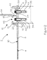
- Figure 2 shows a second cross-section of the fan casing 2 through the region in which the metallic ring 6 is secured to one of a plurality of struts 34 which extend between the metallic ring 6 and an engine core (not shown) of a turbofan engine.
- the struts 34 support the fan casing 2 on the engine core and may comprise a pair of struts 34 disposed on opposite sides of the engine core.
- Each strut comprises two limbs which converge in the radially outward direction and meet at a connecting point 35 which lies against the body portion 24 of the ring 6.
- the metallic ring 6 comprises fastening features in the form of first bores 36 and second bores 38 which extend radially through the metallic ring 6.
- the bores 36, 38 are disposed on opposite sides of the stiffening element 32 such that the first bores 36 are disposed within the stepped region 12, and the second bores 38 are disposed outside the stepped region 12.
- the first and second bores 36, 38 are disposed axially to both sides of the stiffening flange 14 and the stiffening element 32.
- Radially extending bores 40 are provided in the ends of the struts 34. These bores 40 align with the bores 36, 38 in the metallic ring 6.
- Hollow dowels 42 extend through the bores 36, 38 in the metallic ring 6 and into the bores 40 in the ends of the struts 34.
- the hollow dowels 42 are a snug fit within the bores 36, 38, 40 so as to prevent axial or circumferential displacement of the metallic ring 6, and hence the fan casing 2, with respect to the struts 34.
- Fasteners 44 extend through the hollow dowels 42 and engage with threaded portions of the bores 40 in the ends of the struts 34. The fasteners 44 prevent radial displacement of the metallic ring 6, and hence the fan casing 2, with respect to the struts 34.
- threaded inserts may be fitted within the bores 40 to engage the fasteners 44.
- the second portion 18 of the joggle 15 has access apertures 46 which are aligned with the fasteners 44.
- the access apertures 46 provide access to the fasteners 44 and enable the fasteners 44 disposed within the stepped region 12 to be inserted and removed though the body portion 8.
- the stepped portion 12 enables the stiffening flange 14 to be positioned between axially spaced apart fasteners 44 thus ensuring that the loads acting through the stiffening flange 14, act equally on the fasteners 44.
- the stiffening element 32 extends only over the portions of the metallic ring 6 which are adjacent the struts 34.
Landscapes
- Engineering & Computer Science (AREA)
- Mechanical Engineering (AREA)
- General Engineering & Computer Science (AREA)
- Chemical & Material Sciences (AREA)
- Combustion & Propulsion (AREA)
- Structures Of Non-Positive Displacement Pumps (AREA)
Abstract
Description
- This invention relates to a fan casing for a turbofan engine.
- A turbofan engine comprises an engine core about which is disposed a fan casing. Generally, the fan casing is coaxial with the engine core and is supported on the core by a main support structure extending between the fan casing and the core. In addition to the main structure, the rear of the fan casing may be secured to the engine by struts which extend between the engine core and the rear of the fan casing. The struts resist relative motion between the engine core and the rear of the fan casing. The arrangement of the struts, fan casing and fasteners securing the struts to the fan casing must be able to withstand extreme loads such as those generated during a fan-blade-off event (i.e. shedding of a fan blade), for example following a bird strike.
- The fan casing may also be attached to other functional elements such as thrust reverser units.
- In order to improve rigidity of the fan casing it is known to provide the fan casing with a stiffener flange which extends radially outwardly from the fan casing. The stiffener flange is aligned with the struts in a common radial plane so that the forces acting at the root of the flange are transmitted directly through the struts. Typically, the fan casing is provided with hollow dowels which extend through bores in the casing. The dowels resist transverse loading of the fan casing (i.e. rotational and axial loading of the casing). In addition, fasteners extend through the dowels and secure the casing to the struts in the radial direction. The fasteners resist radial loading of the fan casing. The fasteners and dowels are arranged on opposing sides of the stiffening flange. This ensures an even distribution of load about the stiffener flange. The bores in the casing have to be machined with precise diametral tolerance. With composites there has been found to be fibre relaxation which makes it very difficult to achieve the required diametral tolerance to receive the dowels. Composite fibres also reduce in strength significantly when exposed to high temperatures and are liable to deform and tear in the event of an engine fire local to the strut interface under engine loading.
- According to the present invention there is provided a fan casing for a turbofan engine comprising an annular casing component of composite material comprising a body portion having an outwardly directed stiffening flange at one end, the stiffening flange being connected to the body portion by a radially outwardly stepped region, the fan casing also comprising a metallic ring which is coaxial with the annular casing component, the metallic ring being situated at least partially within the stepped region and being secured to the annular casing component.
- The metallic ring may provide an attachment location for the aft struts and the TRU.
- The body portion may have an inner diameter which is substantially equal to the inner diameter of the metallic ring.
- The stepped region may comprise a joggle having a first portion which extends radially outwardly from the main body of the body portion, and a second portion which extends axially from the radially outer edge of the first portion, the stiffening flange extending outwardly from the end of the second portion situated away from the first portion.
- The metallic ring may be fastened to the first portion of the joggle.
- The metallic ring may project axially outwardly from the stepped region.
- The metallic ring may be provided with fastening features disposed axially to both sides of the stiffening flange. The second portion of the joggle may be apertured to provide access to the fastening features disposed to the side of the stiffening flange within the stepped region. The fan casing may be secured to at least one inwardly extending strut by way of fasteners which cooperate with the fastening features.
- The fastening features may comprise bores.
- The metallic ring may be provided with a stiffening element. The stiffening element may comprise a radially extending rib which is disposed within the stepped region. The stiffening element may be substantially radially aligned with the stiffening flange.
- The composite material may be a carbon fibre reinforced composite.
- According to a second aspect of the invention there is provided a turbofan engine comprising an engine core, and a fan casing in accordance with the first aspect of the invention, wherein the fan casing is disposed coaxially with the engine core and is supported on the engine core by a plurality of struts extending between the core and the metallic ring. The struts may be connected to the metallic ring by fasteners extending through hollow dowels received in the bores.
- For a better understanding of the present invention, and to show more clearly how it may be carried into effect, reference will now be made, by way of example, to the accompanying drawings, in which:-
-
Figure 1 is a partial sectional view of a fan casing; and -
Figure 2 is a partial section view of a fan casing connected to a strut. -
Figure 1 shows afan casing 2 comprising anannular component 4 of composite material and a metallic ring 6. Thefan casing 2 is shown in elevational section, with only the upper portion of thefan casing 2 visible. Theannular component 4 and the metallic ring 6 are coaxial, the inner diameter of theannular component 4 being substantially equal to the inner diameter of the metallic ring 6. - The
annular component 4 comprises abody portion 8 having amain body region 10 and astepped region 12. Astiffening flange 14 extends radially outwardly from the circumferential edge of thestepped region 12. Thestiffening flange 14 extends about the entire circumferential edge of thestepped region 12 and is formed integrally with theannular component 4. Theannular component 4 is a monolithic structure comprising a composite material such as a carbon fibre reinforced composite. - The
stepped region 12 comprises ajoggle 15. Thejoggle 15 has afirst portion 16 which extends radially outwardly from themain body region 10, and asecond portion 18 which extends from the radially outer edge of thefirst portion 16 to thestiffening flange 14. Thesecond portion 18 extends substantially coaxially with themain body region 10. Circumferentially spacedopenings 20 are provided in thefirst portion 16. It will be appreciated that the radially extendingfirst portion 16 will add stiffness to theannular component 4 which adds to the stiffness provided by thestiffening flange 14. A reducedstiffness stiffening flange 14 can therefore be used, for example astiffening flange 14 of reduced thickness. - A
second flange 22 extends radially outwardly from the circumferential edge of themain body region 10 opposite thejoggle 15. Circumferentially spaced openings (not shown) are provided inflange 22 to allow attachment to a forward casing portion. Themain body region 10 may be thickened from its centre towards thestepped region 12 and thesecond flange 22 to provide additional strength and stiffness. - The metallic ring 6 comprises a
body portion 24 having aflange 26 which extends radially outwardly from a circumferential edge of thebody portion 24. The metallic ring 6 is arranged so that a portion of the metallic ring 6 is within thestepped region 12, and the remainder projects axially (to the right, as seen in the Figures) from theannular component 4, i.e. beyond thestiffening flange 14. Theflange 26 abuts thefirst portion 16 of thejoggle 15. The diameter of the outer edge of theflange 26 is less than the inner diameter of thesecond portion 18 of thejoggle 15. The metallic ring 6 thus fits within thestepped region 12 with the radially inner surface of the metallic ring 6 aligned in the same circumferential plane as the radially inner surface of themain body region 10. Theflange 26 is provided with circumferentially spacedopenings 28 which correspond to theopenings 20 in thefirst portion 16 of thejoggle 15.Fasteners 30, such as nut and bolt arrangements extend through theopenings first portion 16 of thejoggle 15 and theflange 26 to secure the metallic ring 6 to theannular component 4. - The metallic ring 6 has a
stiffening element 32 comprising a radially outwardly extending flange. Thestiffening element 32 extends circumferentially about the metallic ring 6. Thestiffening element 32 may be aligned with thestiffening flange 14 with respect to the longitudinal axis of thefan casing 2 and so complements the stiffening action of thestiffening flange 14. Thestiffening element 32 may comprise a plain radially extending web as shown inFigure 1 , but in other embodiments thestiffening element 32 may have a peripheral flange at its radially outer end, so as to have, for example, an L-shaped or T-shaped cross-section. Thestiffening element 32 extends about the entire circumferential extent of the metallic ring 6. -
Figure 2 shows a second cross-section of thefan casing 2 through the region in which the metallic ring 6 is secured to one of a plurality ofstruts 34 which extend between the metallic ring 6 and an engine core (not shown) of a turbofan engine. Thestruts 34 support thefan casing 2 on the engine core and may comprise a pair ofstruts 34 disposed on opposite sides of the engine core. Each strut comprises two limbs which converge in the radially outward direction and meet at a connectingpoint 35 which lies against thebody portion 24 of the ring 6. - The metallic ring 6 comprises fastening features in the form of
first bores 36 andsecond bores 38 which extend radially through the metallic ring 6. Thebores element 32 such that the first bores 36 are disposed within the steppedregion 12, and the second bores 38 are disposed outside the steppedregion 12. The first andsecond bores flange 14 and thestiffening element 32.Radially extending bores 40 are provided in the ends of thestruts 34. These bores 40 align with thebores Hollow dowels 42 extend through thebores bores 40 in the ends of thestruts 34. The hollow dowels 42 are a snug fit within thebores fan casing 2, with respect to thestruts 34.Fasteners 44 extend through thehollow dowels 42 and engage with threaded portions of thebores 40 in the ends of thestruts 34. Thefasteners 44 prevent radial displacement of the metallic ring 6, and hence thefan casing 2, with respect to thestruts 34. In an alternative embodiment, for example if thestruts 34, or at least the connectingportion 35, are made from a composite material, threaded inserts may be fitted within thebores 40 to engage thefasteners 44. - The
second portion 18 of thejoggle 15 hasaccess apertures 46 which are aligned with thefasteners 44. The access apertures 46 provide access to thefasteners 44 and enable thefasteners 44 disposed within the steppedregion 12 to be inserted and removed though thebody portion 8. - By securing the
fan casing 2 to thestruts 34 via the metallic ring 6, retention of thefan casing 2 is by fasteners acting directly through the metallic ring 6 and thestruts 34. Concentrated loads acting at thestruts 34 are therefore exerted through the metallic ring 6 rather than the compositeannular component 4. These loads are transferred to theannular component 4 by thefasteners 30, which enable the loads to be spread around the circumference of theannular component 4. Tearing of thefan casing 2 at thestruts 34 during a fan-blade-off event or following an engine fire is therefore less likely to occur. - The stepped
portion 12 enables the stiffeningflange 14 to be positioned between axially spaced apartfasteners 44 thus ensuring that the loads acting through the stiffeningflange 14, act equally on thefasteners 44. - In a variant of the embodiment described above, the stiffening
element 32 extends only over the portions of the metallic ring 6 which are adjacent thestruts 34.
Claims (15)
- A fan casing for a turbofan engine comprising an annular casing component of composite material comprising a body portion having an outwardly directed stiffening flange at one end, the stiffening flange being connected to the body portion by a radially outwardly stepped region, the fan casing also comprising a metallic ring which is coaxial with the annular casing component, the metallic ring being situated at least partially within the stepped region and being secured to the annular casing component.
- A fan casing as claimed in claim 1, wherein the body portion has an inner diameter which is substantially equal to the inner diameter of the metallic ring.
- A fan casing as claimed in claim 2, wherein the stepped region comprises a joggle having a first portion which extends radially outwardly from the main body of the body portion, and a second portion which extends axially from the radially outer edge of the first portion, the stiffening flange extending outwardly from the end of the second portion situated away from the first portion.
- A fan casing as claimed in claim 3, wherein the metallic ring is fastened to the first portion of the joggle.
- A fan casing as claimed in any one of the preceding claims, wherein the metallic ring projects axially outwardly from the stepped region.
- A fan casing as claimed in claim 5, wherein the metallic ring is provided with fastening features disposed axially to both sides of the stiffening flange.
- A fan casing as claimed in claim 6 when appendant to claim 3, wherein the second portion of the joggle is apertured to provide access to the fastening features disposed to the side of the stiffening flange within the stepped region.
- A fan casing as claimed in claim 6 or 7, which is secured to at least one inwardly extending strut by way of fasteners which cooperate with the fastening features.
- A fan casing as claimed in any one of claims 6 to 8, wherein the fastening features comprise bores.
- A fan casing as claimed in any one of the preceding claims, wherein the metallic ring is provided with a stiffening element.
- A fan casing as claimed in claim 10, wherein the stiffening element comprises a radially extending rib which is disposed within the stepped region.
- A fan casing as claimed in claim 11, wherein the stiffening element is substantially radially aligned with the stiffening flange.
- A fan casing as claimed in any one of the preceding claims, wherein the composite material is a carbon fibre reinforced composite.
- A turbofan engine comprising:an engine core, anda fan casing as claimed in any one of the preceding claims, wherein the fan casing is disposed coaxially with the engine core and is supported on the engine core by a plurality of struts extending between the core and the metallic ring.
- A turbofan engine as claimed in claim 14 when appendant to claim 9, wherein the struts are connected to the metallic ring by fasteners extending through hollow dowels received in the bores.
Applications Claiming Priority (1)
| Application Number | Priority Date | Filing Date | Title |
|---|---|---|---|
| GBGB1103583.9A GB201103583D0 (en) | 2011-03-03 | 2011-03-03 | Fan casing for a turbofan engine |
Publications (3)
| Publication Number | Publication Date |
|---|---|
| EP2495402A2 true EP2495402A2 (en) | 2012-09-05 |
| EP2495402A3 EP2495402A3 (en) | 2015-02-25 |
| EP2495402B1 EP2495402B1 (en) | 2016-02-03 |
Family
ID=43904459
Family Applications (1)
| Application Number | Title | Priority Date | Filing Date |
|---|---|---|---|
| EP12153809.4A Not-in-force EP2495402B1 (en) | 2011-03-03 | 2012-02-03 | Fan casing for a turbofan engine |
Country Status (3)
| Country | Link |
|---|---|
| US (1) | US8926277B2 (en) |
| EP (1) | EP2495402B1 (en) |
| GB (1) | GB201103583D0 (en) |
Cited By (1)
| Publication number | Priority date | Publication date | Assignee | Title |
|---|---|---|---|---|
| EP3059400A1 (en) * | 2014-12-31 | 2016-08-24 | General Electric Company | Casing ring assembly with flowpath conduction cut |
Families Citing this family (6)
| Publication number | Priority date | Publication date | Assignee | Title |
|---|---|---|---|---|
| US9498850B2 (en) | 2012-03-27 | 2016-11-22 | Pratt & Whitney Canada Corp. | Structural case for aircraft gas turbine engine |
| WO2014200571A2 (en) * | 2013-02-19 | 2014-12-18 | United Technologies Corporation | Composite attachment structure with 3d weave |
| EP3106289B1 (en) | 2015-06-17 | 2023-10-18 | Raytheon Technologies Corporation | Co-molded metallic fan case containment ring |
| US10830136B2 (en) | 2015-11-19 | 2020-11-10 | General Electric Company | Fan case for use in a turbofan engine, and method of assembling a turbofan engine |
| US10550718B2 (en) | 2017-03-31 | 2020-02-04 | The Boeing Company | Gas turbine engine fan blade containment systems |
| US10487684B2 (en) | 2017-03-31 | 2019-11-26 | The Boeing Company | Gas turbine engine fan blade containment systems |
Family Cites Families (12)
| Publication number | Priority date | Publication date | Assignee | Title |
|---|---|---|---|---|
| GB2010434B (en) * | 1977-12-16 | 1982-06-30 | Rolls Royce | Flanged joint structure for composite materials |
| US5431532A (en) * | 1994-05-20 | 1995-07-11 | General Electric Company | Blade containment system |
| DE60231219D1 (en) | 2002-12-03 | 2009-04-02 | Techspace Aero Sa | Inner shroud of an axial compressor and its use |
| GB2398353B (en) * | 2003-02-14 | 2006-02-15 | Rolls Royce Plc | A gas turbine engine nose cone |
| GB0408825D0 (en) | 2004-04-20 | 2004-05-26 | Rolls Royce Plc | A rotor blade containment assembly for a gas turbine engine |
| US8191254B2 (en) * | 2004-09-23 | 2012-06-05 | Carlton Forge Works | Method and apparatus for improving fan case containment and heat resistance in a gas turbine jet engine |
| DE602006005693D1 (en) | 2006-12-22 | 2009-04-23 | Techspace Aero Milmort | Turbomachinery compressor |
| EP1939459B1 (en) | 2006-12-27 | 2018-04-25 | Safran Aero Boosters SA | System with jaws for connecting two flanges, in particular for a compressor shroud |
| FR2913053B1 (en) * | 2007-02-23 | 2009-05-22 | Snecma Sa | PROCESS FOR MANUFACTURING A GAS TURBINE CASE OF COMPOSITE MATERIAL AND CARTER THUS OBTAINED |
| US8613593B2 (en) * | 2008-12-30 | 2013-12-24 | Rolls-Royce North American Technologies Inc. | Engine case system for a gas turbine engine |
| GB0914679D0 (en) * | 2009-08-24 | 2009-09-30 | Rolls Royce Plc | Adjustable fan case liner and mounting method |
| US8753075B2 (en) * | 2010-07-20 | 2014-06-17 | Rolls-Royce Corporation | Fan case assembly and method |
-
2011
- 2011-03-03 GB GBGB1103583.9A patent/GB201103583D0/en not_active Ceased
-
2012
- 2012-02-03 EP EP12153809.4A patent/EP2495402B1/en not_active Not-in-force
- 2012-02-03 US US13/365,851 patent/US8926277B2/en active Active
Cited By (2)
| Publication number | Priority date | Publication date | Assignee | Title |
|---|---|---|---|---|
| EP3059400A1 (en) * | 2014-12-31 | 2016-08-24 | General Electric Company | Casing ring assembly with flowpath conduction cut |
| US10337353B2 (en) | 2014-12-31 | 2019-07-02 | General Electric Company | Casing ring assembly with flowpath conduction cut |
Also Published As
| Publication number | Publication date |
|---|---|
| US8926277B2 (en) | 2015-01-06 |
| GB201103583D0 (en) | 2011-04-13 |
| EP2495402A3 (en) | 2015-02-25 |
| EP2495402B1 (en) | 2016-02-03 |
| US20120263583A1 (en) | 2012-10-18 |
Similar Documents
| Publication | Publication Date | Title |
|---|---|---|
| US8926277B2 (en) | Fan casing for a turbofan engine | |
| EP2837772B1 (en) | Annulus filler and corresponding stage and gas turbine engine | |
| EP2837774B1 (en) | Annulus filler and corresponding stage and gas turbine engine | |
| EP2940251B1 (en) | Fan containment case | |
| EP1473441B1 (en) | Apparatus for mounting a gas turbine engine | |
| US8672609B2 (en) | Composite fan containment case assembly | |
| EP3093450B1 (en) | Steel soft wall fan case | |
| EP2893172B1 (en) | Assembly for mounting a turbine engine to a pylon | |
| EP2815119B1 (en) | Composite fan containment case assembly | |
| US9200595B2 (en) | Nose cone assembly | |
| JP2017503950A (en) | Composite fan inlet blade containment structure | |
| US7419121B2 (en) | Integrated mount duct for use with airborne auxiliary power units and other turbomachines | |
| CN108691805A (en) | I-beam bucket platform | |
| EP2623729B1 (en) | Gas turbine engine with a fan and booster joint and corresponding method | |
| US20150021455A1 (en) | Turbine engine support part of hybrid structure | |
| US12351294B2 (en) | Propeller for an aircraft turbomachine | |
| EP3144499A1 (en) | Cylindrical case | |
| US8801376B2 (en) | Fabricated intermediate case with engine mounts | |
| EP4675093A2 (en) | Segmented nacelle inlet attachment structure | |
| US10465560B2 (en) | Housing element for an intermediate turbine housing |
Legal Events
| Date | Code | Title | Description |
|---|---|---|---|
| PUAI | Public reference made under article 153(3) epc to a published international application that has entered the european phase |
Free format text: ORIGINAL CODE: 0009012 |
|
| AK | Designated contracting states |
Kind code of ref document: A2 Designated state(s): AL AT BE BG CH CY CZ DE DK EE ES FI FR GB GR HR HU IE IS IT LI LT LU LV MC MK MT NL NO PL PT RO RS SE SI SK SM TR |
|
| AX | Request for extension of the european patent |
Extension state: BA ME |
|
| PUAL | Search report despatched |
Free format text: ORIGINAL CODE: 0009013 |
|
| AK | Designated contracting states |
Kind code of ref document: A3 Designated state(s): AL AT BE BG CH CY CZ DE DK EE ES FI FR GB GR HR HU IE IS IT LI LT LU LV MC MK MT NL NO PL PT RO RS SE SI SK SM TR |
|
| AX | Request for extension of the european patent |
Extension state: BA ME |
|
| RIC1 | Information provided on ipc code assigned before grant |
Ipc: B64D 29/06 20060101ALI20150122BHEP Ipc: F01D 25/24 20060101ALI20150122BHEP Ipc: F02K 3/06 20060101ALI20150122BHEP Ipc: F01D 21/04 20060101AFI20150122BHEP |
|
| RAP1 | Party data changed (applicant data changed or rights of an application transferred) |
Owner name: ROLLS-ROYCE PLC |
|
| 17P | Request for examination filed |
Effective date: 20150813 |
|
| RBV | Designated contracting states (corrected) |
Designated state(s): AL AT BE BG CH CY CZ DE DK EE ES FI FR GB GR HR HU IE IS IT LI LT LU LV MC MK MT NL NO PL PT RO RS SE SI SK SM TR |
|
| GRAP | Despatch of communication of intention to grant a patent |
Free format text: ORIGINAL CODE: EPIDOSNIGR1 |
|
| INTG | Intention to grant announced |
Effective date: 20151027 |
|
| GRAS | Grant fee paid |
Free format text: ORIGINAL CODE: EPIDOSNIGR3 |
|
| GRAA | (expected) grant |
Free format text: ORIGINAL CODE: 0009210 |
|
| AK | Designated contracting states |
Kind code of ref document: B1 Designated state(s): AL AT BE BG CH CY CZ DE DK EE ES FI FR GB GR HR HU IE IS IT LI LT LU LV MC MK MT NL NO PL PT RO RS SE SI SK SM TR |
|
| REG | Reference to a national code |
Ref country code: GB Ref legal event code: FG4D |
|
| REG | Reference to a national code |
Ref country code: AT Ref legal event code: REF Ref document number: 773817 Country of ref document: AT Kind code of ref document: T Effective date: 20160215 Ref country code: CH Ref legal event code: EP |
|
| REG | Reference to a national code |
Ref country code: IE Ref legal event code: FG4D |
|
| REG | Reference to a national code |
Ref country code: DE Ref legal event code: R096 Ref document number: 602012014269 Country of ref document: DE |
|
| REG | Reference to a national code |
Ref country code: DE Ref legal event code: R082 Ref document number: 602012014269 Country of ref document: DE Representative=s name: HERNANDEZ, YORCK, DIPL.-ING., DE |
|
| REG | Reference to a national code |
Ref country code: LT Ref legal event code: MG4D Ref country code: NL Ref legal event code: MP Effective date: 20160203 |
|
| REG | Reference to a national code |
Ref country code: AT Ref legal event code: MK05 Ref document number: 773817 Country of ref document: AT Kind code of ref document: T Effective date: 20160203 |
|
| REG | Reference to a national code |
Ref country code: FR Ref legal event code: PLFP Year of fee payment: 5 |
|
| PG25 | Lapsed in a contracting state [announced via postgrant information from national office to epo] |
Ref country code: ES Free format text: LAPSE BECAUSE OF FAILURE TO SUBMIT A TRANSLATION OF THE DESCRIPTION OR TO PAY THE FEE WITHIN THE PRESCRIBED TIME-LIMIT Effective date: 20160203 Ref country code: FI Free format text: LAPSE BECAUSE OF FAILURE TO SUBMIT A TRANSLATION OF THE DESCRIPTION OR TO PAY THE FEE WITHIN THE PRESCRIBED TIME-LIMIT Effective date: 20160203 Ref country code: HR Free format text: LAPSE BECAUSE OF FAILURE TO SUBMIT A TRANSLATION OF THE DESCRIPTION OR TO PAY THE FEE WITHIN THE PRESCRIBED TIME-LIMIT Effective date: 20160203 Ref country code: GR Free format text: LAPSE BECAUSE OF FAILURE TO SUBMIT A TRANSLATION OF THE DESCRIPTION OR TO PAY THE FEE WITHIN THE PRESCRIBED TIME-LIMIT Effective date: 20160504 Ref country code: IT Free format text: LAPSE BECAUSE OF FAILURE TO SUBMIT A TRANSLATION OF THE DESCRIPTION OR TO PAY THE FEE WITHIN THE PRESCRIBED TIME-LIMIT Effective date: 20160203 Ref country code: NO Free format text: LAPSE BECAUSE OF FAILURE TO SUBMIT A TRANSLATION OF THE DESCRIPTION OR TO PAY THE FEE WITHIN THE PRESCRIBED TIME-LIMIT Effective date: 20160503 |
|
| PG25 | Lapsed in a contracting state [announced via postgrant information from national office to epo] |
Ref country code: IS Free format text: LAPSE BECAUSE OF FAILURE TO SUBMIT A TRANSLATION OF THE DESCRIPTION OR TO PAY THE FEE WITHIN THE PRESCRIBED TIME-LIMIT Effective date: 20160603 Ref country code: AT Free format text: LAPSE BECAUSE OF FAILURE TO SUBMIT A TRANSLATION OF THE DESCRIPTION OR TO PAY THE FEE WITHIN THE PRESCRIBED TIME-LIMIT Effective date: 20160203 Ref country code: BE Free format text: LAPSE BECAUSE OF NON-PAYMENT OF DUE FEES Effective date: 20160229 Ref country code: NL Free format text: LAPSE BECAUSE OF FAILURE TO SUBMIT A TRANSLATION OF THE DESCRIPTION OR TO PAY THE FEE WITHIN THE PRESCRIBED TIME-LIMIT Effective date: 20160203 Ref country code: LV Free format text: LAPSE BECAUSE OF FAILURE TO SUBMIT A TRANSLATION OF THE DESCRIPTION OR TO PAY THE FEE WITHIN THE PRESCRIBED TIME-LIMIT Effective date: 20160203 Ref country code: SE Free format text: LAPSE BECAUSE OF FAILURE TO SUBMIT A TRANSLATION OF THE DESCRIPTION OR TO PAY THE FEE WITHIN THE PRESCRIBED TIME-LIMIT Effective date: 20160203 Ref country code: RS Free format text: LAPSE BECAUSE OF FAILURE TO SUBMIT A TRANSLATION OF THE DESCRIPTION OR TO PAY THE FEE WITHIN THE PRESCRIBED TIME-LIMIT Effective date: 20160203 Ref country code: PL Free format text: LAPSE BECAUSE OF FAILURE TO SUBMIT A TRANSLATION OF THE DESCRIPTION OR TO PAY THE FEE WITHIN THE PRESCRIBED TIME-LIMIT Effective date: 20160203 Ref country code: PT Free format text: LAPSE BECAUSE OF FAILURE TO SUBMIT A TRANSLATION OF THE DESCRIPTION OR TO PAY THE FEE WITHIN THE PRESCRIBED TIME-LIMIT Effective date: 20160603 Ref country code: LT Free format text: LAPSE BECAUSE OF FAILURE TO SUBMIT A TRANSLATION OF THE DESCRIPTION OR TO PAY THE FEE WITHIN THE PRESCRIBED TIME-LIMIT Effective date: 20160203 |
|
| REG | Reference to a national code |
Ref country code: CH Ref legal event code: PL |
|
| PG25 | Lapsed in a contracting state [announced via postgrant information from national office to epo] |
Ref country code: EE Free format text: LAPSE BECAUSE OF FAILURE TO SUBMIT A TRANSLATION OF THE DESCRIPTION OR TO PAY THE FEE WITHIN THE PRESCRIBED TIME-LIMIT Effective date: 20160203 Ref country code: LI Free format text: LAPSE BECAUSE OF NON-PAYMENT OF DUE FEES Effective date: 20160229 Ref country code: DK Free format text: LAPSE BECAUSE OF FAILURE TO SUBMIT A TRANSLATION OF THE DESCRIPTION OR TO PAY THE FEE WITHIN THE PRESCRIBED TIME-LIMIT Effective date: 20160203 Ref country code: CH Free format text: LAPSE BECAUSE OF NON-PAYMENT OF DUE FEES Effective date: 20160229 |
|
| REG | Reference to a national code |
Ref country code: DE Ref legal event code: R097 Ref document number: 602012014269 Country of ref document: DE |
|
| PG25 | Lapsed in a contracting state [announced via postgrant information from national office to epo] |
Ref country code: CZ Free format text: LAPSE BECAUSE OF FAILURE TO SUBMIT A TRANSLATION OF THE DESCRIPTION OR TO PAY THE FEE WITHIN THE PRESCRIBED TIME-LIMIT Effective date: 20160203 Ref country code: SM Free format text: LAPSE BECAUSE OF FAILURE TO SUBMIT A TRANSLATION OF THE DESCRIPTION OR TO PAY THE FEE WITHIN THE PRESCRIBED TIME-LIMIT Effective date: 20160203 Ref country code: RO Free format text: LAPSE BECAUSE OF FAILURE TO SUBMIT A TRANSLATION OF THE DESCRIPTION OR TO PAY THE FEE WITHIN THE PRESCRIBED TIME-LIMIT Effective date: 20160203 Ref country code: SK Free format text: LAPSE BECAUSE OF FAILURE TO SUBMIT A TRANSLATION OF THE DESCRIPTION OR TO PAY THE FEE WITHIN THE PRESCRIBED TIME-LIMIT Effective date: 20160203 |
|
| REG | Reference to a national code |
Ref country code: IE Ref legal event code: MM4A |
|
| PLBE | No opposition filed within time limit |
Free format text: ORIGINAL CODE: 0009261 |
|
| STAA | Information on the status of an ep patent application or granted ep patent |
Free format text: STATUS: NO OPPOSITION FILED WITHIN TIME LIMIT |
|
| PG25 | Lapsed in a contracting state [announced via postgrant information from national office to epo] |
Ref country code: BE Free format text: LAPSE BECAUSE OF FAILURE TO SUBMIT A TRANSLATION OF THE DESCRIPTION OR TO PAY THE FEE WITHIN THE PRESCRIBED TIME-LIMIT Effective date: 20160203 |
|
| 26N | No opposition filed |
Effective date: 20161104 |
|
| PG25 | Lapsed in a contracting state [announced via postgrant information from national office to epo] |
Ref country code: IE Free format text: LAPSE BECAUSE OF NON-PAYMENT OF DUE FEES Effective date: 20160203 |
|
| REG | Reference to a national code |
Ref country code: FR Ref legal event code: PLFP Year of fee payment: 6 |
|
| PG25 | Lapsed in a contracting state [announced via postgrant information from national office to epo] |
Ref country code: BG Free format text: LAPSE BECAUSE OF FAILURE TO SUBMIT A TRANSLATION OF THE DESCRIPTION OR TO PAY THE FEE WITHIN THE PRESCRIBED TIME-LIMIT Effective date: 20160503 Ref country code: SI Free format text: LAPSE BECAUSE OF FAILURE TO SUBMIT A TRANSLATION OF THE DESCRIPTION OR TO PAY THE FEE WITHIN THE PRESCRIBED TIME-LIMIT Effective date: 20160203 |
|
| PG25 | Lapsed in a contracting state [announced via postgrant information from national office to epo] |
Ref country code: MT Free format text: LAPSE BECAUSE OF FAILURE TO SUBMIT A TRANSLATION OF THE DESCRIPTION OR TO PAY THE FEE WITHIN THE PRESCRIBED TIME-LIMIT Effective date: 20160203 |
|
| PG25 | Lapsed in a contracting state [announced via postgrant information from national office to epo] |
Ref country code: MC Free format text: LAPSE BECAUSE OF FAILURE TO SUBMIT A TRANSLATION OF THE DESCRIPTION OR TO PAY THE FEE WITHIN THE PRESCRIBED TIME-LIMIT Effective date: 20160203 |
|
| REG | Reference to a national code |
Ref country code: FR Ref legal event code: PLFP Year of fee payment: 7 |
|
| PG25 | Lapsed in a contracting state [announced via postgrant information from national office to epo] |
Ref country code: HU Free format text: LAPSE BECAUSE OF FAILURE TO SUBMIT A TRANSLATION OF THE DESCRIPTION OR TO PAY THE FEE WITHIN THE PRESCRIBED TIME-LIMIT; INVALID AB INITIO Effective date: 20120203 Ref country code: CY Free format text: LAPSE BECAUSE OF FAILURE TO SUBMIT A TRANSLATION OF THE DESCRIPTION OR TO PAY THE FEE WITHIN THE PRESCRIBED TIME-LIMIT Effective date: 20160203 |
|
| PG25 | Lapsed in a contracting state [announced via postgrant information from national office to epo] |
Ref country code: MT Free format text: LAPSE BECAUSE OF FAILURE TO SUBMIT A TRANSLATION OF THE DESCRIPTION OR TO PAY THE FEE WITHIN THE PRESCRIBED TIME-LIMIT Effective date: 20160229 Ref country code: MK Free format text: LAPSE BECAUSE OF FAILURE TO SUBMIT A TRANSLATION OF THE DESCRIPTION OR TO PAY THE FEE WITHIN THE PRESCRIBED TIME-LIMIT Effective date: 20160203 Ref country code: TR Free format text: LAPSE BECAUSE OF FAILURE TO SUBMIT A TRANSLATION OF THE DESCRIPTION OR TO PAY THE FEE WITHIN THE PRESCRIBED TIME-LIMIT Effective date: 20160203 Ref country code: LU Free format text: LAPSE BECAUSE OF NON-PAYMENT OF DUE FEES Effective date: 20160203 |
|
| PG25 | Lapsed in a contracting state [announced via postgrant information from national office to epo] |
Ref country code: AL Free format text: LAPSE BECAUSE OF FAILURE TO SUBMIT A TRANSLATION OF THE DESCRIPTION OR TO PAY THE FEE WITHIN THE PRESCRIBED TIME-LIMIT Effective date: 20160203 |
|
| PGFP | Annual fee paid to national office [announced via postgrant information from national office to epo] |
Ref country code: FR Payment date: 20230223 Year of fee payment: 12 |
|
| PGFP | Annual fee paid to national office [announced via postgrant information from national office to epo] |
Ref country code: GB Payment date: 20230214 Year of fee payment: 12 Ref country code: DE Payment date: 20230227 Year of fee payment: 12 |
|
| P01 | Opt-out of the competence of the unified patent court (upc) registered |
Effective date: 20230528 |
|
| REG | Reference to a national code |
Ref country code: DE Ref legal event code: R119 Ref document number: 602012014269 Country of ref document: DE |
|
| GBPC | Gb: european patent ceased through non-payment of renewal fee |
Effective date: 20240203 |
|
| PG25 | Lapsed in a contracting state [announced via postgrant information from national office to epo] |
Ref country code: DE Free format text: LAPSE BECAUSE OF NON-PAYMENT OF DUE FEES Effective date: 20240903 |
|
| PG25 | Lapsed in a contracting state [announced via postgrant information from national office to epo] |
Ref country code: GB Free format text: LAPSE BECAUSE OF NON-PAYMENT OF DUE FEES Effective date: 20240203 |
|
| PG25 | Lapsed in a contracting state [announced via postgrant information from national office to epo] |
Ref country code: FR Free format text: LAPSE BECAUSE OF NON-PAYMENT OF DUE FEES Effective date: 20240229 |
|
| PG25 | Lapsed in a contracting state [announced via postgrant information from national office to epo] |
Ref country code: GB Free format text: LAPSE BECAUSE OF NON-PAYMENT OF DUE FEES Effective date: 20240203 Ref country code: FR Free format text: LAPSE BECAUSE OF NON-PAYMENT OF DUE FEES Effective date: 20240229 Ref country code: DE Free format text: LAPSE BECAUSE OF NON-PAYMENT OF DUE FEES Effective date: 20240903 |