EP2495387B1 - Solar radiation shielding apparatus - Google Patents
Solar radiation shielding apparatus Download PDFInfo
- Publication number
- EP2495387B1 EP2495387B1 EP11734657.7A EP11734657A EP2495387B1 EP 2495387 B1 EP2495387 B1 EP 2495387B1 EP 11734657 A EP11734657 A EP 11734657A EP 2495387 B1 EP2495387 B1 EP 2495387B1
- Authority
- EP
- European Patent Office
- Prior art keywords
- input shaft
- section
- clutch
- output shaft
- turning force
- Prior art date
- Legal status (The legal status is an assumption and is not a legal conclusion. Google has not performed a legal analysis and makes no representation as to the accuracy of the status listed.)
- Not-in-force
Links
Images



Classifications
-
- E—FIXED CONSTRUCTIONS
- E06—DOORS, WINDOWS, SHUTTERS, OR ROLLER BLINDS IN GENERAL; LADDERS
- E06B—FIXED OR MOVABLE CLOSURES FOR OPENINGS IN BUILDINGS, VEHICLES, FENCES OR LIKE ENCLOSURES IN GENERAL, e.g. DOORS, WINDOWS, BLINDS, GATES
- E06B9/00—Screening or protective devices for wall or similar openings, with or without operating or securing mechanisms; Closures of similar construction
- E06B9/56—Operating, guiding or securing devices or arrangements for roll-type closures; Spring drums; Tape drums; Counterweighting arrangements therefor
-
- E—FIXED CONSTRUCTIONS
- E06—DOORS, WINDOWS, SHUTTERS, OR ROLLER BLINDS IN GENERAL; LADDERS
- E06B—FIXED OR MOVABLE CLOSURES FOR OPENINGS IN BUILDINGS, VEHICLES, FENCES OR LIKE ENCLOSURES IN GENERAL, e.g. DOORS, WINDOWS, BLINDS, GATES
- E06B9/00—Screening or protective devices for wall or similar openings, with or without operating or securing mechanisms; Closures of similar construction
- E06B9/24—Screens or other constructions affording protection against light, especially against sunshine; Similar screens for privacy or appearance; Slat blinds
- E06B9/26—Lamellar or like blinds, e.g. venetian blinds
- E06B9/262—Lamellar or like blinds, e.g. venetian blinds with flexibly-interconnected horizontal or vertical strips; Concertina blinds, i.e. upwardly folding flexible screens
-
- E—FIXED CONSTRUCTIONS
- E06—DOORS, WINDOWS, SHUTTERS, OR ROLLER BLINDS IN GENERAL; LADDERS
- E06B—FIXED OR MOVABLE CLOSURES FOR OPENINGS IN BUILDINGS, VEHICLES, FENCES OR LIKE ENCLOSURES IN GENERAL, e.g. DOORS, WINDOWS, BLINDS, GATES
- E06B9/00—Screening or protective devices for wall or similar openings, with or without operating or securing mechanisms; Closures of similar construction
- E06B9/56—Operating, guiding or securing devices or arrangements for roll-type closures; Spring drums; Tape drums; Counterweighting arrangements therefor
- E06B9/68—Operating devices or mechanisms, e.g. with electric drive
-
- E—FIXED CONSTRUCTIONS
- E06—DOORS, WINDOWS, SHUTTERS, OR ROLLER BLINDS IN GENERAL; LADDERS
- E06B—FIXED OR MOVABLE CLOSURES FOR OPENINGS IN BUILDINGS, VEHICLES, FENCES OR LIKE ENCLOSURES IN GENERAL, e.g. DOORS, WINDOWS, BLINDS, GATES
- E06B9/00—Screening or protective devices for wall or similar openings, with or without operating or securing mechanisms; Closures of similar construction
- E06B9/24—Screens or other constructions affording protection against light, especially against sunshine; Similar screens for privacy or appearance; Slat blinds
- E06B2009/2423—Combinations of at least two screens
- E06B2009/2447—Parallel screens
- E06B2009/2452—Parallel screens moving independently
-
- E—FIXED CONSTRUCTIONS
- E06—DOORS, WINDOWS, SHUTTERS, OR ROLLER BLINDS IN GENERAL; LADDERS
- E06B—FIXED OR MOVABLE CLOSURES FOR OPENINGS IN BUILDINGS, VEHICLES, FENCES OR LIKE ENCLOSURES IN GENERAL, e.g. DOORS, WINDOWS, BLINDS, GATES
- E06B9/00—Screening or protective devices for wall or similar openings, with or without operating or securing mechanisms; Closures of similar construction
- E06B9/24—Screens or other constructions affording protection against light, especially against sunshine; Similar screens for privacy or appearance; Slat blinds
- E06B9/26—Lamellar or like blinds, e.g. venetian blinds
- E06B9/262—Lamellar or like blinds, e.g. venetian blinds with flexibly-interconnected horizontal or vertical strips; Concertina blinds, i.e. upwardly folding flexible screens
- E06B2009/2622—Gathered vertically; Roman, Austrian or festoon blinds
Definitions
- the present invention relates to a solar radiation shielding apparatus that lifts and lowers two shielding members, each being hung from a head rail, with operation of a single operating cord.
- a solar radiation member lifting and lowering apparatus that supports first and second solar radiation shielding members suspended from a head box and can lift and lower the first and second solar radiation shielding members independently by effecting the operation of first and second lifting and lowering operation sections with operation of one endless operating cord hung from the head box has been disclosed, compare for example JP4119692B in particular claim 1 and paragraphs [0043] and [0157].
- the solar radiation member lifting and lowering apparatus includes first and second stopper units that allow a state in which the solar radiation shielding members are not lowered as a result of the first and second solar radiation shielding members being prevented from being lowered under the own weights thereof or a state in which the solar radiation shielding members are lowered as a result of the first and second solar radiation shielding members being allowed to be lowered under the own weights thereof to be selected, a first clutch unit that allows a lifting operation of the first solar radiation shielding member and a lowering operation thereof due to the own weight thereof by making the first lifting and lowering operation section and the first stopper unit operate with operation of the operating cord to one side without lifting or lowering the second solar radiation shielding member or an operation to prevent the falling of the first solar radiation shielding member due to the own weight thereof to stop the falling of the first solar radiation shielding member due to the own weight thereof to be selected, and a second clutch unit that allows a lifting operation of the second solar radiation shielding member and a lowering operation thereof due to the own weight thereof by making the second
- the first clutch unit is formed of a first rotating drum that is rotated based on the operation of the operating cord, a first transfer drum driving the first lifting and lowering operation section, and a first clutch section transferring the rotation of the first rotating drum to the first transfer drum.
- the first clutch section is configured such that the turning force of the first rotating drum based on the operation of the operating cord to one side can be transferred to the first transfer drum and the first transfer drum is freely rotatable independently of the first rotating drum when the first transfer drum is rotated based on the falling of the first solar radiation shielding member due to the own weight thereof.
- the second clutch unit is formed of a second rotating drum that is rotated based on the operation of the operating cord, a second transfer drum driving the second lifting and lowering operation section, and a second clutch section transferring the rotation of the second rotating drum to the second transfer drum.
- the second clutch section is configured such that the turning force of the second rotating drum based on the operation of the operating cord to the other side can be transferred to the second transfer drum and the second transfer drum is freely rotatable independently of the second rotating drum when the second transfer drum is rotated based on the falling of the second solar radiation shielding member due to the own weight thereof.
- first and second clutch sections are each formed of a clutch drum rotatably supported on a shaft, a guide groove formed on the outer periphery of the clutch drum, a clutch ball that moves along the guide groove, and a stop spring that prevents the rotation of the clutch drum based on the turning force exerted from the clutch drum and integrally rotates the first or second rotating drum and the clutch drum based on the turning force exerted from the first or second rotating drum.
- the above-described guide groove is formed of an engagement groove that makes it possible to transfer the turning force of the first or second rotating drum to the first or second transfer drum via the clutch ball and a release groove leading out of the engagement groove in such a way as to be offset to the side where the first or second rotating drum is located, the release groove allowing the first or second transfer drum to rotate freely with respect to the first or second rotating drum.
- the turning force of the first rotating drum is transferred to the first transfer drum via the clutch ball
- the turning force of the second rotating drum is not transferred to the second transfer drum
- the turning force of the second rotating drum is transferred to the second transfer drum via the clutch ball
- the turning force of the first rotating drum is not transferred to the first transfer drum.
- the solar radiation shielding members can be lifted and lowered easily.
- Document JPH10 176471 discloses a controller producing two kinds of rotative power, one for turning a first take-up shaft in the direction of lowering a screen by operating an operating cord in one direction and the other for turning a second take-up shaft in the direction of lowering the screen by operating the operating cord in the other direction, that is provided at an operating device;
- An urging device for urging the screen to move in the direction of winding-up, first clutches and for allowing the take-up shafts to turn in the direction of raising the screen after being turned from the state of holding the screen from rising in the direction of lowering the screen within a specified angle of turning, and second clutches and that transmit the rotative power produced at the controller to the take-up shafts and do not transmit the rotation of the take-up shafts urged by the urging device to the controller are provided at the inside of the take-up shafts.
- the component elements such as the clutch ball and the stop spring are used and the guide groove formed of the engagement groove and the release groove is formed in the clutch drum, which makes the structure of the clutch unit complicated.
- the solar radiation member lifting and lowering apparatus disclosed in JP4119692B since the first or second clutch drum moves with the clutch ball along the guide groove in an axial direction of a first or second shaft, the entire lengths of the first and second clutch units are increased accordingly.
- a first object of the present invention is to provide a solar radiation shielding apparatus that can lift and lower a first shielding member and a second shielding member independently with a relatively simple structure with operation of one operating cord.
- a second object of the present invention is to provide a solar radiation shielding apparatus that can reduce the entire lengths of first and second clutches by performing switching by the first and second clutches with radial revolution and reciprocating movement of first and second input shafts.
- a solar radiation shielding apparatus including: a head rail 13; first and second shielding members 11 and 12 hung from the head rail 13; a first lifting and lowering unit 21 provided in the head rail 13 and connected to the first shielding member 11; a second lifting and lowering unit 22 provided in the head rail 13 and connected to the second shielding member 12; and a single operating cord 14 coupled to the first and second lifting and lowering units 21 and 22, the operating cord 14 lifting and lowering the first and second shielding members 11 and 12 independently by driving the first and second lifting and lowering units 21 and 22, a rotating member 26 is rotatably attached to the head rail 13, the operating cord 14 is wound around the rotating member 26, the first lifting and lowering unit 21 has a first input shaft 21a rotatably attached to the head rail 13, the first input shaft 21a to which a turning force of the rotating member 26 is transferred without a turning force transfer mechanism 50 or via the turning force transfer mechanism 50, a
- a second aspect of the present invention is based on the first aspect, and, as shown in FIGS. 1 and 2 , the first clutch 31 has a first engaging section 31b revolvable or reciprocatable in a radial direction of the first input shaft 21a, and the first clutch 31 transfers the turning force from the rotating member 26, the turning force in one direction, to the first output shaft 21b via the first input shaft 21a by the first engaging section 31b and does not transfer the turning force from the rotating member 26, the turning force in the other direction, to the first output shaft 21a and the turning force from the first output shaft 21b to the first input shaft 21a, and the second clutch 32 has a second engaging section 32b revolvable or reciprocatable in a radial direction of the second input shaft 22a, and the second clutch 32 transfers the turning force from the rotating member 26, the turning force in the other direction, to the second output shaft 22b via the second input shaft 22a by the second engaging section 32b and does not transfer the turning force from the rotating member 26, the turning force in one direction, to the second
- a third aspect of the present invention based on the second aspect, and, as shown in FIGS. 1 and 2 , as a result of the first engaging section 31b rotating or moving to the outside in the radial direction of the first input shaft 21a, the first output shaft 21b engages the first input shaft 21a and rotates in synchronization with the first input shaft 21a, and, as a result of the first engaging section 31b rotating or moving to the inside in the radial direction of the first input shaft 21a, the first output shaft 21b is moved out of engagement with the first input shaft 21a and stops rotating in synchronization with the first input shaft 21a, and, as a result of the second engaging section 32b rotating or moving to the outside in the radial direction of the second input shaft 22a, the second output shaft 22b engages the second input shaft 22a and rotates in synchronization with the second input shaft 22a, and, as a result of the second engaging section 32b rotating or moving to the inside in the radial direction of the second input shaft 22a, the second output shaft 22b
- a fourth aspect of the present invention is based on the first to third aspects, and, as shown in FIGS. 1 and 2 , the first clutch 31 has a first output drum 31a attached to the first output shaft 21b in such a way that the first output drum 31a cannot rotate, the first output drum 31a in which a first cylindrical section 31c that is loosely fitted over the first input shaft 21a is provided, the first cylindrical section 31c having an inner circumferential surface in which a first engaged section 31d is formed, a first clutch drum 61 rotatably fitted over the first input shaft 21a in such a way that the first clutch drum 61 is located inside the first cylindrical section 31c, a first cam 71 fitted over the first input shaft 21a in such a way that the first cam 71 cannot rotate and is located inside the first cylindrical section 31c, the first cam 71 in which a first arm section 71a extending to the outside in the radial direction of the first input shaft 21a is formed, and the first engaging section 31b revolvably attached to a side face of
- a fifth aspect of the present invention is based on the fourth aspect, and, as shown in FIGS. 8 to 10 , an angle which a flat surface of the first engaged section 131d, the flat surface at which the first engaged section 131d makes contact with the first engaging section 131b, forms with a flat surface making contact with an outer circumferential surface of the first cylindrical section 131c in the first engaged section 131d is set at an acute angle, and an angle which a flat surface of the second engaged section 132d, the flat surface at which the second engaged section 132d makes contact with the second engaging section 132b, forms with a flat surface making contact with an outer circumferential surface of the second cylindrical section 132c in the second engaged section 132d is set at an acute angle.
- a sixth aspect of the present invention is based on the fourth or fifth aspect, and, as shown in FIGS. 1 and 4 , between the first input shaft 21a and the first clutch drum 61, a first resistance applying mechanism 81 preventing rotation of the first clutch drum 61 relative to the first input shaft 21a is provided, and, between the second input shaft 22a and the second clutch drum 62, a second resistance applying mechanism 82 preventing rotation of the second clutch drum 62 relative to the second input shaft 22a is provided.
- a seventh aspect of the present invention is based on the fourth to sixth aspects, and, as shown in FIGS. 1 and 3 , a first return spring mechanism 91 urging the first engaging section 31b in such a way that the first engaging section 31b retracts to the inside in the radial direction of the first input shaft 21a is provided in the first engaging section 31b, and a second return spring mechanism 92 urging the second engaging section 32b in such a way that the second engaging section 32b retracts to the inside in the radial direction of the second input shaft 22a is provided in the second engaging section 32b.
- the rotating member rotates in one direction, and, since the turning force of the rotating member in one direction is transferred to the first output shaft via the first input shaft and the first clutch or via the turning force transfer mechanism, the first input shaft, and the first clutch, the first shielding member rises.
- the second clutch does not transfer the above-described turning force in one direction to the second output shaft.
- the first stopper switches the first shielding member to a falling state.
- the second clutch does not transfer the above-described turning force in one direction to the second output shaft.
- this turning force is not transferred to the first input shaft by the action of the first clutch and therefore is not transferred to the second input shaft.
- the operating cord is pulled in one direction.
- the first stopper switches the first shielding member to a stopped state.
- the second clutch does not transfer the above-described turning force in one direction to the second output shaft.
- the rotating member rotates in the other direction, and, since the turning force of the rotating member in the other direction is transferred to the second output shaft via the turning force transfer mechanism, the second input shaft, and the second clutch or via the second input shaft and the second clutch, the second shielding member rises. At this time, although the turning force of the rotating member in the other direction is transferred to the first clutch via the first input shaft or via the turning force transfer mechanism and the first input shaft, the first clutch does not transfer the above-described turning force in the other direction to the first output shaft.
- the second stopper switches the second shielding member to a falling state.
- the first clutch does not transfer the above-described turning force in the other direction to the first output shaft.
- the second shielding member falls, although the second output shaft rotates in a direction in which the second shielding member is unreeled, this turning force is not transferred to the second input shaft by the action of the second clutch and therefore is not transferred to the first input shaft.
- the operating cord is pulled in the other direction.
- the second stopper switches the second shielding member to a stopped state.
- the first clutch does not transfer the above-described turning force in the other direction to the first output shaft.
- the first and second clutches since switching by the first and second clutches is performed by the revolution and reciprocating movement of the first and second engaging sections in the radial direction of the first and second input shafts, the first and second clutches do not extend in the longitudinal direction of the first and second input shafts. This makes it possible to reduce the entire lengths of the first and second clutches.
- the first cam rotates with the first input shaft by the rotation of the rotating member in one direction
- the first arm section rotates the first engaging section in such a way that the first engaging section juts to the outside in the radial direction of the first input shaft
- the first engaging section engages the first engaged section of the first output drum, and the turning force of the first clutch drum is transferred to the first output drum
- the second cam rotates with the second input shaft by the rotation of the rotating member in the other direction
- the second arm section rotates the second engaging section in such a way that the second engaging section juts to the outside in the radial direction of the second input shaft
- the second engaging section engages the second engaged section of the second output drum, and the turning force of the second clutch drum is transferred to the second output drum.
- first and second clutches do not extend in the longitudinal direction of the first and second input shafts, it is possible to reduce the entire lengths of the first and second clutches. Moreover, since the first output shaft rotates in a direction in which the first shielding member is unreeled due to the weight of the first shielding member and the first engaging section is retracted to the inside in the radial direction of the first input shaft by the rotation of the first output drum, the above-described turning force of the first output shaft is not transferred to the first input shaft.
- the second output shaft rotates in a direction in which the second shielding member is unreeled due to the weight of the second shielding member and the second engaging section is retracted to the inside in the radial direction of the second input shaft by the rotation of the second output drum, the turning force of the second output shaft is not transferred to the second input shaft.
- the first and second shielding members are always lifted and lowered independently.
- an angle which a flat surface of the first engaged section, the flat surface at which the first engaged section makes contact with the first engaging section, forms with a flat surface making contact with an outer circumferential surface of the first cylindrical section in the first engaged section is set at an acute angle, that is, since vector setting is made so that, when the first cylindrical section rotates in a direction in which the first engaged section is brought into contact with the first engaging section by pressure, the first engaging section escapes in the circumferential direction by using the turning force from the first cylindrical section, the first engaged section rarely bites mechanically the first engaging section and the first engaging section rarely bites mechanically the first arm section. As a result, the first engaging section is promptly removed from the first engaged section.
- an angle which a flat surface of the second engaged section, the flat surface at which the second engaged section makes contact with the second engaging section, forms with a flat surface making contact with an outer circumferential surface of the second cylindrical section in the second engaged section is set at an acute angle, that is, since vector setting is made so that, when the second cylindrical section rotates in a direction in which the second engaged section is brought into contact with the second engaging section by pressure, the second engaging section escapes in the circumferential direction by using the turning force from the second cylindrical section, the second engaged section rarely bites mechanically the second engaging section and the second engaging section rarely bites mechanically the second arm section. As a result, the second engaging section is promptly removed from the second engaged section.
- the first resistance applying mechanism preventing rotation of the first clutch drum relative to the first input shaft is provided between the first input shaft and the first clutch drum and the second resistance applying mechanism preventing rotation of the second clutch drum relative to the second input shaft is provided between the second input shaft and the second clutch drum, at the time of initial torque of the first input shaft, the first clutch drum follows the rotation of the first input shaft by the first resistance applying mechanism and, at the time of initial torque of the second input shaft, the second clutch drum follows the rotation of the second input shaft by the second resistance applying mechanism.
- the first engaging section attached to the first clutch drum does not accidentally engage the first engaged section of the first output drum
- the second engaging section attached to the second clutch drum does not accidentally engage the second engaged section of the second output drum.
- the first return spring mechanism urging the first engaging section in such a way that the first engaging section retracts to the inside in the radial direction of the first input shaft is provided in the first engaging section and the second return spring mechanism urging the second engaging section in such a way that the second engaging section retracts to the inside in the radial direction of the second input shaft is provided in the second engaging section, even when the first output shaft rotates in a direction in which the first shielding member is unreeled due to the weight of the first shielding member and the first output drum rotates by the rotation of the first output shaft, since the first return spring mechanism maintains a state in which the first engaging section is retracted to the inside in the radial direction of the first input shaft, the turning force of the first output shaft is not transferred to the first input shaft.
- the second output shaft rotates in a direction in which the second shielding member is unreeled due to the weight of the second shielding member and the second output drum rotates by the rotation of the second output shaft
- the second return spring mechanism maintains a state in which the second engaging section is retracted to the inside in the radial direction of the second input shaft
- the turning force of the second output shaft is not transferred to the second input shaft.
- the first and second shielding members can be reliably lifted and lowered independently.
- a solar radiation shielding apparatus is a roman shade.
- a roman shade 10 includes a head rail 13, first and second clothes 11 and 12 hung from the head rail 13, a first lifting and lowering unit 21 that is provided in the head rail 13 and is connected to the first cloth 11, a second lifting and lowering unit 22 that is provided in the head rail 13 and is connected to the second cloth 12, and a single operating cord 14 that is coupled to the first and second lifting and lowering units 21 and 22 and lifts and lowers the first and second clothes 11 and 12 independently by driving the first and second lifting and lowering units 21 and 22.
- the head rail 13 has a rail main body 18 that is attached to a wall surface 17 ( FIG.
- the rail main body 18 is formed by extrusion or pultrusion performed on metal such as an aluminum alloy and, as shown in FIG. 6 in detail, has a top portion 18a, a front wall 18b hung from a front edge of the top portion 18a, and a back wall 18c hung from a back edge of the top portion 18a.
- a space surrounded with the top portion 18a, the front wall 18b, and the back wall 18c is divided into an upper space 18e located on an upper side and a lower space 18f located on a lower side by a partition wall 18d.
- reference numeral 24 in FIG. 6 denotes a wood screw for securing the fixing bracket 16 to the wall surface 17.
- a pulley 26 is rotatably housed.
- a boss 23a is provided in such a way as to project to the inside of the case 23 toward the lower space 18f of the rail main body 18, a drive shaft 27 is rotatably fitted over the boss 23a, and the pulley 26 is fitted (spline fitted) to the drive shaft 27 in such a way that relative rotation is impossible.
- the above-described ring-shaped (endless) ball chain operating cord 14 is wound.
- the first and second clothes 11 and 12 have the width that is about the same as the length of the head rail 13.
- An upper edge of the first cloth 11 is attached to a front face of the head rail 13, that is, an upper part of a front face of the front wall 18b of the head rail 13, and an upper edge of the second cloth 12 is attached to a rear face of the head rail 13, that is, a lower part of a rear face of the back wall 18c of the head rail 13.
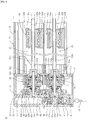
- the first lifting and lowering unit 21 has a first input shaft 21a rotatably attached to a lower part of the clutch case 19, a first output shaft 21b rotatably attached to the head rail 13 coaxially with the first input shaft 21a, a first clutch 31 provided between the first input shaft 21a and the first output shaft 21b, and a first stopper 41 provided on the first output shaft 21b ( FIG. 1 ).
- One end of the above-described first input shaft 21a is inserted into the above-described drive shaft 27 in such a way that relative rotation is impossible, and the other end of the first input shaft 21a is inserted into a first output drum 31a, which will be described later, in such a way that relative rotation is possible.
- the first input shaft 21a is provided coaxially with the drive shaft 27, and the turning force of the pulley 26 is transferred to the first input shaft 21a via the drive shaft 27.
- Reference numeral 51 in FIGS. 1 and 7 denotes a first gear formed integrally with the drive shaft 27.
- the second lifting and lowering unit 22 has a second input shaft 22a rotatably attached to an upper part of the clutch case 19, a second output shaft 22b rotatably attached to the head rail 13 coaxially with the second input shaft 22a, a second clutch 32 provided between the second input shaft 22a and the second output shaft 22b, and a second stopper 42 provided on the second output shaft 22b ( FIG. 1 ).
- a second gear 52 is rotatably attached, and the second gear 52 engages the first gear 51.
- One end of the second input shaft 22a is inserted into the second gear 52 in such a way that relative rotation is impossible, and the other end of the second input shaft 22a is inserted into a second output drum 32a, which will be described later, in such a way that relative rotation is possible.
- the turning force of the pulley 26 is transferred to the second input shaft 22a via the drive shaft 27, the first gear 51, and the second gear 52.
- the number of teeth of the first gear 51 is equal to the number of teeth of the second gear 52, and the first and second gears 51 and 52 form a turning force transfer mechanism 50.
- the pulley is provided on the side where the first input shaft is located.
- the pulley may be provided on the side where the second input shaft is located. In this case, the turning force of the pulley is transferred to the second input shaft without the second gear and the first gear and is transferred to the first input shaft via the second gear and the first gear.
- the first output shaft 21b is provided in the lower space 18f of the rail main body 18 in such a way as to extend in the direction of the length of the lower space 18f ( FIGS. 1 , 6 , and 7 ).
- the first output drum 31a is attached in such a way that the first output drum 31a cannot rotate, and the first output drum 31a is rotatably attached to the lower part of the clutch case 19.
- the other end of the first output shaft 21b is rotatably attached to the rail main body 18.
- the first output shaft 21b is coupled to the first cloth 11 via a first wind-up drum 21c and a first lifting and lowering cord 21d.
- the first wind-up drum 21c is fitted over the first output shaft 21b in such a way that relative rotation is impossible, and the first lifting and lowering cord 21d is wound around the first wind-up drum 21c in such a way that the first lifting and lowering cord 21d can be unreeled therefrom. Furthermore, the first wind-up drum 21c is rotatably held by a first drum support 21e, and the first lifting and lowering cord 21d wound around the first wind-up drum 21c is led out of the lower space 18f to a space below the rail main body 18 by a first guide member 21f and hung therefrom ( FIGS. 6 and 7 ).
- first cord rings 21g are attached with a predetermined space left between them in a vertical direction.
- the first lifting and lowering cord 21d hung from the lower space 18f is placed through the first cord rings 21g and routed vertically downward, and then the lower end of the first lifting and lowering cord 21d is connected to the first cord ring 21g located on the lowermost end of the first cloth 11.
- the first wind-up drum 21c rotates in the same direction as the first output shaft 21b, the first lifting and lowering cord 21d is wound around the first wind-up drum 21c or unreeled from the first wind-up drum 21c, and the first cloth 11 rises or falls.
- the second output shaft 22b is provided in the upper space 18e of the rail main body 18 in such a way as to extend in the direction of the length of the upper space 18e ( FIGS. 1 , 6 , and 7 ).
- the second output drum 32a is attached in such a way that the second output drum 32a cannot rotate, and the second output drum 32a is rotatably attached to the upper part of the clutch case 19.
- the other end of the second output shaft 22b is rotatably attached to the rail main body 18.
- the second output shaft 22b is coupled to the second cloth 12 via a second wind-up drum 22c and a second lifting and lowering cord 22d.
- the second wind-up drum 22c is fitted over the second output shaft 22b in such a way that relative rotation is impossible, and the second lifting and lowering cord 22d is wound around the second wind-up drum 22c in such a way that the second lifting and lowering cord 22d can be unreeled therefrom. Furthermore, the second wind-up drum 22c is rotatably held by a second drum support 22e, and the second lifting and lowering cord 22d wound around the second wind-up drum 22c is led out of the upper space 18e to a space behind the rail main body 18 by a second guide member 22f and hung therefrom ( FIGS. 6 and 7 ).
- a plurality of second cord rings 22g are attached with a predetermined space left between them in a vertical direction.
- the second lifting and lowering cord 22d hung from the upper space 18e is placed through the second cord rings 22g and routed vertically downward, and then the lower end of the second lifting and lowering cord 22d is connected to the second cord ring 22g located on the lowermost end of the second cloth 12.
- the second wind-up drum 22c rotates in the same direction as the second output shaft 22b, the second lifting and lowering cord 22d is wound around the second wind-up drum 22c or unreeled from the second wind-up drum 22c, and the second cloth 12 rises or falls.
- the first clutch 31 is housed in the lower part of the clutch case 19 ( FIG. 1 ).
- the first clutch 31 has the above-described first output drum 31a attached to the first output shaft 21b in such a way that the first output drum 31a cannot rotate, a first clutch drum 61 rotatably fitted over the first input shaft 21a, a first cam 71 fitted over the first input shaft 21a in such a way that the first cam 71 cannot rotate, and first engaging sections 31b revolvably attached to the first clutch drum 61 ( FIGS. 1 , 2 , and 4 ).
- first output drum 31a a large diameter first cylindrical section 31c that is loosely fitted over the first input shaft 21a is provided, and, in an inner circumferential surface of the first cylindrical section 31c, three first engaged sections 31d are formed at regular intervals (equiangularly) in a circumferential direction. Moreover, a first cam shaft 31e is fitted over the first input shaft 21a in such a way that relative rotation is impossible.
- the first clutch drum 61 is formed of a pair of first disks 61a and 61b, each having a diameter slightly smaller than the inside diameter of the first cylindrical section 31c, and three first supporting shafts 61c connecting the first disks 61a and 61b to each other with a predetermined space left between them.
- the pair of first disks 61a and 61b is loosely inserted into the first cylindrical section 31c in a state in which the pair of first disks 61a and 61b is rotatably fitted over the first cam shaft 31e.
- the three first supporting shafts 61c are disposed on the same circumference of a circle having a center on the central axis of the first disks 61a and 61b at regular intervals (equiangularly) in a circumferential direction, and, in this state, both ends of each of the three first supporting shafts 61c are attached by insertion to the pair of first disks 61a and 61b.
- the above-described first clutch drum 61 is located inside the first cylindrical section 31c.
- the first cam 71 is formed integrally with the first cam shaft 31e ( FIGS. 1 , 2 , and 4 ). As a result, the first cam 71 cannot rotate with respect to the first input shaft 21a. Moreover, the first cam 71 is formed of three first arm sections 71a radially extending to the outside in the radial direction of the first input shaft 21a in such a way that the three first arm sections 71a are located inside the first cylindrical section 31c. Furthermore, the first arm sections 71a are each tapered from the base end toward the tip, and the angles, which the first arm sections 71a form with the adjacent first arm sections 71a are set at the same angle (120 degrees).
- three first engaging sections 31b are provided, and the first engaging sections 31b are each shaped like a letter L.
- the base ends of the three first engaging sections 31b are revolvably fitted over the three first supporting shafts 61c.
- the three first engaging sections 31b are revolvably attached to an inner surface of the first clutch drum 61 in a state in which the three first engaging sections 31b are sandwiched between the pair of first disks 61a and 61b.
- bending outer corner portions of the three first engaging sections 31b each face a corresponding one of the base ends of the three first arm sections 71a, and the tips of the three first engaging sections 31b each face a corresponding one of the three first engaged sections 31d.
- the first engaging sections 31b rotate about the first supporting shafts 61c in one direction, and the tips of the first engaging sections 31b jut to the outside in the radial direction of the first input shaft 21a and engage the first engaged sections 31d; at the time of rotation of the pulley 26 in the other direction or at the time of rotation of the first output shaft 21b, the first engaging sections 31b rotate about the first supporting shafts 61c in the other direction, and the tips of the first engaging sections 31b are retracted to the inside in the radial direction of the first input shaft 21a and do not engage the first engaged sections 31d.
- the first output shaft 21b engages the first input shaft 21a and rotates in synchronization with the first input shaft 21a; as a result of the first engaging sections 31b rotating to the inside in the radial direction of the first input shaft 21a at the time of rotation of the pulley 26 in the other direction or at the time of rotation of the first output shaft 21b, the first output shaft 21b is moved out of engagement with the first input shaft 21a and stops rotating in synchronization with the first input shaft 21a.
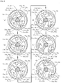
- an angle ⁇ at which the first arm sections 71a rotate from a state in which the first engaging sections 31b are retracted to the innermost positions in the radial direction of the first input shaft 21a ( FIG. 2(a) ) to a state in which the first engaging sections 31b jut to the outermost positions in the radial direction of the first input shaft 21a ( FIG. 2(f) ) is about 50 degrees and is extremely small.
- the second clutch 32 has the same structure as the first clutch 31 and is housed in the upper part of the clutch case 19 ( FIG. 1 ).
- the second clutch 32 has the above-described second output drum 32a attached to the second output shaft 22b in such a way that the second output drum 32a cannot rotate, a second clutch drum 62 rotatably fitted over the second input shaft 22a, a second cam 72 fitted over the second input shaft 22a in such a way that the second cam 72 cannot rotate, and second engaging sections 32b revolvably attached to the second clutch drum 62 ( FIGS. 1 , 2 , and 4 ).
- a large diameter second cylindrical section 32c that is loosely fitted over the second input shaft 22a is provided, and, in an inner circumferential surface of the second cylindrical section 32c, three second engaged sections 32d are formed at regular intervals (equiangularly) in a circumferential direction.
- a second cam shaft 32e is fitted over the second input shaft 22a in such a way that relative rotation is impossible.
- the second clutch drum 62 is formed of a pair of second disks 62a and 62b, each having a diameter slightly smaller than the inside diameter of the second cylindrical section 32c, and three second supporting shafts 62c connecting the second disks 62a and 62b to each other with a predetermined space left between them.
- the pair of second disks 62a and 62b is loosely inserted into the second cylindrical section 32c in a state in which the pair of second disks 62a and 62b is rotatably fitted over the second cam shaft 32e.
- the three second supporting shafts 62c are disposed on the same circumference of a circle having a center on the central axis of the second disks 62a and 62b at regular intervals (equiangularly) in a circumferential direction, and, in this state, both ends of each of the three second supporting shafts 62c are attached by insertion to the pair of second disks 62a and 62b.
- the above-described second clutch drum 62 is located inside the second cylindrical section 32c.
- the second cam 72 is formed integrally with the second cam shaft 32e ( FIGS. 1 , 2 , and 4 ). As a result, the second cam 72 cannot rotate with respect to the second input shaft 22a. Moreover, the second cam 72 is formed of three second arm sections 72a radially extending to the outside in the radial direction of the second input shaft 22a in such a way that the three second arm sections 72a are located inside the second cylindrical section 32c. Furthermore, the second arm sections 72a are each tapered from the base end toward the tip, and the angles, which the second arm sections 72a form with the adjacent second arm sections 72a are set at the same angle (120 degrees). In this embodiment, three second engaging sections 32b are provided, and the second engaging sections 32b are each shaped like a letter L.
- the base ends of the three second engaging sections 32b are revolvably fitted over the three second supporting shafts 62c.
- the three second engaging sections 32b are revolvably attached to an inner surface of the second clutch drum 62 in a state in which the three second engaging sections 32b are sandwiched between the pair of second disks 62a and 62b.
- bending outer corner portions of the three second engaging sections 32b each face a corresponding one of the base ends of the three second arm sections 72a, and the tips of the three second engaging sections 32b each face a corresponding one of the three second engaged sections 32d.
- the second engaging sections 32b rotate about the second supporting shafts 62c in one direction, and the tips of the second engaging sections 32b jut to the outside in the radial direction of the second input shaft 22a and engage the second engaged sections 32d; at the time of rotation of the pulley 26 in one direction or at the time of rotation of the second output shaft 22b, the second engaging sections 32b rotate about the second supporting shafts 62c in the other direction, and the tips of the second engaging sections 32b are retracted to the inside in the radial direction of the second input shaft 22a and do not engage the second engaged sections 32d.
- the second output shaft 22b engages the second input shaft 22a and rotates in synchronization with the second input shaft 22a; as a result of the second engaging sections 32b rotating to the inside in the radial direction of the second input shaft 22a at the time of rotation of the pulley 26 in one direction or at the time of rotation of the second output shaft 22b, the second output shaft 22b is moved out of engagement with the second input shaft 22a and stops rotating in synchronization with the second input shaft 22a.
- an angle 0 at which the second arm sections 72a rotate from a state in which the second engaging sections 32b are retracted to the innermost positions in the radial direction of the second input shaft 22a ( FIG. 2(a) ) to a state in which the second engaging sections 32b jut to the outermost positions in the radial direction of the second input shaft 22a ( FIG. 2(f) ) is about 50 degrees and is extremely small.
- an angle ⁇ which a flat surface of the first engaged section 31d, the flat surface at which the first engaged section 31d makes contact with the first engaging section 31b, forms with a flat surface making contact with an outer circumferential surface of the first cylindrical section 31c in the first engaged section 31d is an acute angle (in this embodiment, about 63 degrees)
- an angle ⁇ which a flat surface of the second engaged section 32d, the flat surface at which the second engaged section 32d makes contact with the second engaging section 32b, forms with a flat surface making contact with an outer circumferential surface of the second cylindrical section 32c in the second engaged section 32d is an acute angle (in this embodiment, about 63 degrees).
- the first stopper 41 switches the first cloth 11 to a falling state or a stopped state with slight operation of the operating cord 14 in one direction ( FIGS. 1 , 5 , and 7 ).
- the first stopper 41 has a first cylindrical cam 41a that is fitted over the first output shaft 21b and has a first cam groove 41e formed in an outer circumferential surface, a first cam case 41c that is attached to the rail main body 18 in such a way as to house the first cylindrical cam 41a and has formed therein a first guide groove 41b extending in the axial direction of the first output shaft 21b, and a first rolling element 41d rolling in an overlapping space of the first cam groove 41e and the first guide groove 41b ( FIG. 1 ). As shown in FIG.
- the first cam groove 41e has an endless first left edge groove 41f formed in a left edge-side outer circumferential surface of the first cylindrical cam 41a in such a way as to extend in the circumferential direction of the first cylindrical cam 41a, an endless first right edge groove 41g formed in a right edge-side outer circumferential surface of the first cylindrical cam 41a in such a way as to extend in the circumferential direction of the first cylindrical cam 41a, a first coupling groove 41h formed between the first left edge groove 41f and the first right edge groove 41g in such a way as to extend in the circumferential direction of the first cylindrical cam 41a, the first coupling groove 41h connected, at one end thereof, to the first left edge groove 41f and connected, at the other end thereof, to the first right edge groove 41g, a first V-shaped groove 41i connected, at one end thereof, to the first coupling groove 41h and connected, at the other end thereof, to the first right edge groove 41g between the first coupling groove 41h and the first right edge groove 41g
- the above-described first coupling groove 41h is formed from the first left edge groove 41f to the first right edge groove 41g in the form of a left-handed spiral. Moreover, in the first left edge groove 41f, a first left curved portion 41k curved to the left edge side of the first cylindrical cam 41a is formed, and a connection at which the first coupling groove 41h is connected to the first left edge groove 41f is formed in such a way as to coincide with one end of the first left curved portion 41k of the first left edge groove 41f. In addition, the first left edge groove 41f and the first coupling groove 41h are connected in such a way that the first left edge groove 41k is nearly aligned with the first coupling groove 41h.
- first right edge groove 41g a first right curved portion 41m curved to the right edge side of the first cylindrical cam 41a is formed, and a connection at which the first V-shaped groove 41i is connected to the first right edge groove 41g is formed in such a way as to coincide with one end of the first right curved portion 41m of the first right edge groove 41g.
- first right edge groove 41g and the first V-shaped groove 41i are connected in such a way that the first right edge groove 41g is nearly aligned with an end of the first V-shaped groove 41i.
- first V-shaped groove 41i is connected to the first coupling groove 41h near a connection between the first left edge groove 41f and the first coupling groove 41h
- the other end of the first V-shaped groove 41i is connected to the first right edge groove 41g near a connection between the first right edge groove 41g and the first coupling groove 41h.
- the first recessed portion 41j is formed to have a size that allows the first recessed portion 41j to house almost half of the first rolling element 41d. The remaining half of the first rolling element 41d is housed in the first guide groove 41b.
- first V-shaped groove 41i is formed in the shape of a somewhat deformed letter V so that the first rolling element 41d housed in the first recessed portion 41j is guided to the first coupling groove 41h, not to the first right edge groove 41g, by the rotation of the first cylindrical cam 41a.
- the first stopper 41 stops the rotation of the first wind-up drum 21c in a direction in which the first lifting and lowering cord 21d is unreeled and the first cloth 11 is lowered, and, after the first wind-up drum 21c is rotated again in one direction with slight operation of the operating cord 14 in one direction from this state to lift the first cloth 11 again by the first lifting and lowering cord 21d, when the hand is disengaged from the operating cord 14, the first stopper 41 allows the rotation of the first wind-up drum 21c in a direction in which the first lifting and lowering cord 21d is unreeled and the first cloth 11 is lowered.
- the second stopper 42 has the same structure as the first stopper 41 and switches the second cloth 12 to a falling state or a stopped state with slight operation of the operating cord 14 in the other direction ( FIGS. 1 , 5 , and 7 ).
- the second stopper 42 has a second cylindrical cam 42a that is fitted over the second output shaft 22b and has a second cam groove 42e formed in an outer circumferential surface, a second cam case 42c that is attached to the rail main body 18 in such a way as to house the second cylindrical cam 42a and has formed therein a second guide groove 42b extending in the axial direction of the second output shaft 22b, and a second rolling element 42d rolling in an overlapping space of the second cam groove 42e and the second guide groove 42b ( FIG.
- the second cam groove 42e has an endless second left edge groove 42f formed in a left edge-side outer circumferential surface of the second cylindrical cam 42a in such a way as to extend in the circumferential direction of the second cylindrical cam 42a, an endless second right edge groove 42g formed in a right end side outer circumferential surface of the second cylindrical cam 42a in such a way as to extend in the circumferential direction of the second cylindrical cam 42a, a second coupling groove 42h formed between the second left edge groove 42f and the second right edge groove 42g in such a way as to extend in the circumferential direction of the second cylindrical cam 42a, the second coupling groove 42h connected, at one end thereof, to the second left edge groove 42f and connected, at the other end thereof, to the second right edge groove 42g, a second V-shaped groove 42i connected, at one end thereof, to the second coupling groove 42h and connected, at the other end thereof, to the second right edge groove 42g between the second coupling groove 42h and
- the above-described second coupling groove 42h is formed from the second left edge groove 42f to the second right edge groove 42g in the form of a left-handed spiral. Moreover, in the second left edge groove 42f, a second left curved portion 42k curved to the left side of the second cylindrical cam 42a is formed, and a connection at which the second coupling groove 42h is connected to the second left edge groove 42f is formed in such a way as to coincide with one end of the second left curved portion 42k of the second left edge groove 42f. In addition, the second left edge groove 42f and the second coupling groove 42h are connected in such a way that the second left edge groove 42f is nearly aligned with the second coupling groove 42h.
- a second right curved portion 42m curved to the right edge side of the second cylindrical cam 42a is formed, and a connection at which the second V-shaped groove 42i is connected to the second right edge groove 42g is formed in such a way as to coincide with one end of the second right curved portion 42m of the second right edge groove 42g.
- the second right edge groove 42g and the second V-shaped groove 42i are connected in such a way that the second right edge groove 42m is nearly aligned with an end of the second V-shaped groove 42i.
- one end of the second V-shaped groove 42i is connected to the second coupling groove 42h near a connection between the second left edge groove 42f and the second coupling groove 42h, and the other end of the second V-shaped groove 42i is connected to the second right edge groove 42g near a connection between the second right edge groove 42g and the second coupling groove 42h.
- the second recessed portion 42j is formed to have a size that allows the second recessed portion 42j to house almost half of the second rolling element 42d. The remaining half of the second rolling element 42d is housed in the second guide groove 42b.
- the second V-shaped groove 42i is formed in the shape of a somewhat deformed letter V so that the second rolling element 42d housed in the second recessed portion 42j is guided to the second coupling groove 42h, not to the second right edge groove 42g, by the rotation of the second cylindrical cam 42a.
- the second stopper 42 stops the rotation of the second wind-up drum 22c in a direction in which the second lifting and lowering cord 22d is unreeled and the second cloth 12 is lowered, and, after the second wind-up drum 22c is rotated again in one direction with slight operation of the operating cord 14 in the other direction from this state to lift the second cloth 12 again by the second lifting and lowering cord 22d, when the hand is disengaged from the operating cord 14, the second stopper 42 allows the rotation of the second wind-up drum 22c in a direction in which the second lifting and lowering cord 22d is unreeled and the second cloth 12 is lowered.
- a first resistance applying mechanism 81 is provided between the first input shaft 21a and the first clutch drum 61, and, between the second input shaft 22a and the second clutch drum 62, a second resistance applying mechanism 82 is provided ( FIGS. 1 and 4 ).
- the first resistance applying mechanism 81 is formed of a first pressure contact plate 81a fitted over the first cam shaft 31e and a first wave washer 81b interposed between the first pressure contact plate 81a and the first disk 61a.
- the first clutch drum 61 and the first resistance applying mechanism 81 are attached to the first cam shaft 31e in a state in which the first clutch drum 61 and the first resistance applying mechanism 81 are sandwiched between a pair of C-shaped snap rings 81c, 81c and a pair of flat washers 81d, 81d and a thrust load is applied to the first clutch drum 61 and the first resistance applying mechanism 81 by the first wave washer 81b.
- the second resistance applying mechanism 82 has the same structure as the first resistance applying mechanism 81.
- the second resistance applying mechanism 82 is formed of a second pressure contact plate 82a fitted over the second cam shaft 32e and a second wave washer 82b interposed between the second pressure contact plate 82a and the second disk 62a.
- the second clutch drum 62 and the second resistance applying mechanism 82 are attached to the second cam shaft 32e in a state in which the second clutch drum 62 and the second resistance applying mechanism 82 are sandwiched between a pair of C-shaped snap rings 82c, 82c and a pair of flat washers 82d, 82d and a thrust load is applied to the second clutch drum 62 and the second resistance applying mechanism 82 by the second wave washer 82b.
- a thrust load is applied to the second clutch drum 62 and the second resistance applying mechanism 82 by the second wave washer 82b.
- a first return spring mechanism 91 is provided in the first engaging sections 31b, and, in the second engaging sections 32b, a second return spring mechanism 92 is provided ( FIGS. 1 and 3 ).
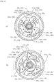
- the first return spring mechanism 91 is formed of a first base 91a rotatably fitted over the first cam shaft 31e, three first curved arm sections 91b jutting from the first base 91a while being curved outward in the radial direction of the first input shaft 21a, and three first pin sections 91c provided at the tips of the three first curved arm sections 91b ( FIG. 3 ).
- the first base 91a, the three first curved arm sections 91b, and the three first pin sections 91c are integrally formed of synthetic resin, and the first pin sections 91c at the tips of the three first curved arm sections 91b are attached by insertion to portions near the tips of the three first engaging sections 31b.
- the angles, which the first curved arm sections 91b form with the adjacent first curved arm sections 91b, are set at the same angle (120 degrees). Furthermore, when an application of the external force acting on the first engaging sections 31b is ended in a state in which the first engaging sections 31b jut to the outside in the radial direction of the first input shaft 21a ( FIG.
- the second return spring mechanism 92 has the same structure as the first return spring mechanism 91 and is formed of a second base 92a rotatably fitted over the second cam shaft 32e, three second curved arm sections 92b jutting from the second base 92a while being curved outward in the radial direction of the second input shaft 22a, and three second pin sections 92c provided at the tips of the three second curved arm sections 92b ( FIG. 3 ).
- the second base 92a, the three second curved arm sections 92b, and the three second pin sections 92c are integrally formed of synthetic resin, and the second pin sections 92c at the tips of the three second curved arm sections 92b are attached by insertion to portions near the tips of the three second engaging sections 32b.
- the angles, which the second curved arm sections 92b form with the adjacent second curved arm sections 92b, are set at the same angle (120 degrees).
- the elasticity of resin of the second curved arm section 92b retracts the second engaging sections 32b to the inside in the radial direction of the second input shaft 22a ( FIG. 3(b) ).
- the second clutch 32 does not transfer the turning force of the pulley 26 in one direction to the second output shaft 22b.
- the reason is as follows (hereinafter, referred to as a first reason).
- the pulley 26 rotates in one direction
- the direction of rotation of the second input shaft 22a is reversed by the engagement between the first gear 51 and the second gear 52, and the second input shaft 22a rotates in the other direction.
- the second arm sections 72a of the second cam 72 rotate in the other direction (a direction indicated by a dashed arrow in FIG.
- the second arm sections 72a do not push the second engaging sections 32b to the outside in the radial direction of the second input shaft 22a, and the second engaging sections 32b are maintained in a state in which the second engaging sections 32b are retracted in the radial direction of the second input shaft 22a by the elasticity of resin of the second curved arm sections 92b of the second return spring mechanism 92 ( FIG. 2(a) and FIG. 3(a) ). Therefore, the second clutch 32 does not transfer the turning force of the pulley 26 in one direction to the second output shaft 22b.
- the first rolling element 41d is housed in the first recessed portion 41j due to the weight of the first cloth 11, even when the turning force in a direction in which the first cloth 11 is unreeled due to the weight of the first cloth 11 acts on the first output shaft 21b, the first output shaft 21b does not rotate, and the first cloth 11 stops.
- the first cylindrical cam 41a of the first stopper 41 slightly rotates less than 360 degrees in a direction in which the first cloth 11 is unreeled, and, although the first output shaft 21b also rotates in the same direction, the rotation of the first output shaft 21b is hardly transferred to the first and second input shafts 21a and 22a.
- the reason is as follows (hereinafter referred to as a second reason). Since the rotation of the first output shaft 21b is the rotation in a direction in which the first engaging sections 31b are moved out of engagement with the first engaged sections 31d of the first output drum 31a, only when the first input shaft 21a rotates about 50 degrees, which is an extremely small angle, the first engaging sections 31b are moved out of engagement with the first engaged sections 31d. As a result, since the turning force of the above-described first output shaft 21b is hardly transferred to the first input shaft 21a, the turning force of the above-described first output shaft 21b is also hardly transferred to the second input shaft 22a.
- the first rolling element 41d When the operating cord 14 is slightly pulled in one direction, for example, when the first cylindrical cam 41a is rotated 0.2 to 0.3 turn while the first cloth 11 is in a stopped state by the first stopper 41, that is, while the first rolling element 41d is maintained in a state in which the first rolling element 41d is housed in the first recessed portion 41j, the first rolling element 41d enters the first coupling groove 41h.
- the first rolling element 41d enters the first left edge groove 41f due to the weight of the first cloth 11, the first cylindrical cam 41a rotates in such a way that the first rolling element 41d rolls in the first left edge groove 41f in the direction indicated by a dashed arrow in FIG.
- the first cloth 11 is switched to a falling state.
- the second clutch 32 does not transfer the turning force of the pulley 26 in one direction to the second output shaft 22b.
- the reason is the same as the first reason described above.
- the first cylindrical cam 41a of the first stopper 41 rotates in a direction in which the first cloth 11 is unreeled, and the first output shaft 21b also rotates in the same direction.
- the rotation of the first output shaft 21b is hardly transferred to the first and second input shafts 21a and 22a.
- the operating cord 14 is pulled in one direction.
- a first speed controller (not shown) functioning as a centrifugal brake is provided in the head rail 13, and the first speed controller reduces the rotational speed of the first output shaft 21b when the rotational speed becomes excessively high.
- the second cylindrical cam 42a rotates in such a way that the second rolling element 42d of the second stopper 42 rolls in the second right edge groove 42g in the direction indicated by a solid arrow in FIG. 5 .
- the first clutch 31 does not transfer the turning force of the pulley 26 in the other direction to the first output shaft 21b.
- the reason is as follows (hereinafter, referred to as a third reason).
- the first arm sections 71a do not push the first engaging sections 31b to the outside in the radial direction of the first input shaft 21a, and the first engaging sections 31b are maintained in a state in which the first engaging sections 31b are retracted in the radial direction of the first input shaft 21a by the elasticity of resin of the first curved arm sections 91b of the first return spring mechanism 91 ( FIG. 2 (a) and FIG. 3(a) ). Therefore, the first clutch 31 does not transfer the turning force of the pulley 26 in the other direction to the first output shaft 21b.
- the second rolling element 42d is housed in the second recessed portion 42j due to the weight of the second cloth 12, even when the turning force in a direction in which the second cloth 12 is unreeled due to the weight of the second cloth 12 acts on the second output shaft 22b, the second output shaft 22b does not rotate, and the second cloth 12 stops.
- the second cylindrical cam 42a of the second stopper 42 slightly rotates less than 360 degrees in a direction in which the second cloth 12 is unreeled, and, although the second output shaft 22b also rotates in the same direction, the rotation of the second output shaft 22b is hardly transferred to the second and first input shafts 22a and 21a.
- the reason is as follows (hereinafter referred to as a fourth reason). Since the rotation of the second output shaft 22b is the rotation in a direction in which the second engaging sections 32b are moved out of engagement with the second engaged sections 32d of the second output drum 32a, only when the second input shaft 22a rotates about 50 degrees, which is an extremely small angle, the second engaging sections 32b are moved out of engagement with the second engaged sections 32d. As a result, since the turning force of the above-described second output shaft 22b is hardly transferred to the second input shaft 22a, the turning force of the above-described second output shaft 22b is also hardly transferred to the first input shaft 21a.
- the second rolling element 42d When the operating cord 14 is slightly pulled in the other direction, for example, when the second cylindrical cam 42a is rotated 0.2 to 0.3 turn while the second cloth 12 is in a stopped state by the second stopper 42, that is, when the second rolling element 42d is maintained in a state in which the second rolling element 12d is housed in the second recessed portion 42j, the second rolling element 42d enters the second coupling groove 42h.
- the second rolling element 42d enters the second left edge groove 42f due to the weight of the second cloth 12, the second cylindrical cam 42a rotates in such a way that the second rolling element 42d rolls in the second left edge groove 42f in the direction indicated by a dashed arrow in FIG.
- the second cloth 12 is switched to a falling state.
- the first clutch 31 does not transfer the turning force of the pulley 26 in the other direction to the first output shaft 21b.
- the reason is the same as the third reason described above.
- the second cylindrical cam 42a of the second stopper 42 rotates in a direction in which the second cloth 12 is unreeled, and the second output shaft 22b also rotates in the same direction.
- the rotation of the second output shaft 22b is hardly transferred to the second and first input shafts 22a and 21a.
- the operating cord 14 is pulled in the other direction.
- a second speed controller (not shown) functioning as a centrifugal brake is provided in the head rail 13, and the second speed controller reduces the rotational speed of the second output shaft 22b when the rotational speed becomes excessively high. Therefore, it is possible to lift and lower the first and second clothes 11 and 12 independently.
- the first resistance applying mechanism 81 is provided between the first input shaft 21a and the first clutch drum 61, at the time of initial torque of the first input shaft 21a, the first clutch drum 61 follows the rotation of the first input shaft 21a by the first resistance applying mechanism 81. As a result, the first engaging sections 31b attached to the first clutch drum 61 do not accidentally engage the first engaged sections 31d of the first output drum 31a.
- the second resistance applying mechanism 82 is provided between the second input shaft 22a and the second clutch drum 62, at the time of initial torque of the second input shaft 22a, the second clutch drum 62 follows the rotation of the second input shaft 22a by the second resistance applying mechanism 82.
- an angle ⁇ which a flat surface of the first engaged section 31d, the flat surface at which the first engaged section 31d makes contact with the first engaging section 31b, forms with a flat surface making contact with an outer circumferential surface of the first cylindrical section 31c in the first engaged section 31d is set at an acute angle (in this embodiment, about 63 degrees), that is, since vector setting is made so that, when the first cylindrical section 31c rotates in a direction (a direction indicated by a chain double-dashed arrow in FIG.
- the first engaging section 31b escapes in the circumferential direction by using the turning force from the first cylindrical section 31c, the first engaged section 31d rarely bites mechanically the first engaging section 31b and the first engaging section 31b rarely bites mechanically the first arm section 71a. As a result, the first engaging section 31b is promptly removed from the first engaged section 31d.
- an angle ⁇ which a flat surface of the second engaged section 32d, the flat surface at which the second engaged section 32d makes contact with the second engaging section 32b, forms with a flat surface making contact with an outer circumferential surface of the second cylindrical section 32c in the second engaged section 32d is set at an acute angle (in this embodiment, about 63 degrees), that is, since vector setting is made so that, when the second cylindrical section 32c rotates in a direction (a direction indicated by a chain double-dashed arrow in FIG.
- FIGS. 8 to 11 show a second embodiment of the present invention.
- the same reference characters as those in FIGS. 1 to 4 denote the same parts.
- an angle ⁇ which a flat surface of a first engaged section 131d, the flat surface at which the first engaged section 131d makes contact with a first engaging section 131b, forms with a flat surface making contact with an outer circumferential surface of a first cylindrical section 131c in the first engaged section 131d is set at an acute angle (in this embodiment, about 50 degrees) which is smaller than the angle in the first embodiment
- an angle ⁇ which a flat surface of a second engaged section 132d, the flat surface at which the second engaged section 132d makes contact with a second engaging section 132b, forms with a flat surface making contact with an outer circumferential surface of a second cylindrical section 132c in the second engaged section 132d is set at an acute angle (in this embodiment, about 50 degrees) which is smaller
- a pulley 126 is rotatably housed in a pulley case 123.
- a boss 123a is provided in such a way as to project to the inside of the case 123 toward a lower space 18f of a rail main body 18, a drive shaft 127 is rotatably fitted over the boss 123a, and the pulley 126 is fitted (spline fitted) to the drive shaft 127 in such a way that relative rotation is impossible.
- a ring-shaped (endless) ball chain operating cord 14 is wound around the pulley 126.
- a drive gear 153 is integrally provided in such a way as to be located between the pulley case 123 and a clutch case 119. Furthermore, to the pulley case 123 and the clutch case 119, an intermediate gear 154 that is located between the pulley case 123 and the clutch case 119 and engages the above-described drive gear 153 is rotatably attached. To the intermediate gear 154, one end of a second input shaft 22a of a second lifting and lowering unit 122 is attached by insertion, and, a second driven gear 152 is fitted over the second input shaft 22a in such a way as to be located in an upper part of the clutch case 119.
- first driven gear 151 that is located inside the clutch case 119 and engages the second driven gear 152 is fitted over the first input shaft 21a.
- the turning force of the pulley 126 is transferred to the second input shaft 22a via the drive shaft 127, the drive gear 153, the intermediate gear 154, and the second driven gear 152 and is transferred to the first input shaft 21a via the drive shaft 127, the drive gear 153, the intermediate gear 154, the second driven gear 152, and the first driven gear 151.
- the drive gear 153 is formed to have a smaller number of teeth than the intermediate gear 154, and the first driven gear 151 is formed to have the same number of teeth as that of the second driven gear 152.
- the above-described drive gear 153, intermediate gear 154, first driven gear 151, and second driven gear 152 form a turning force transfer mechanism 150.
- a first clutch 131 is housed in the lower part of the clutch case 119 ( FIG. 8 ).
- the first clutch 131 has a first output drum 131a attached to a first output shaft 21b in such a way that the first output drum 1.31a cannot rotate, a first clutch drum 161 rotatably fitted over the first input shaft 21a, a first cam 171 fitted over the first input shaft 21a in such a way that the first cam 171 cannot rotate, and first engaging sections 131b revolvably attached to the first clutch drum 161 ( FIGS. 8 , 9 , and 11 ).
- the large diameter first cylindrical section 131c that is loosely fitted over the first input shaft 21a is provided, and, in an inner circumferential surface of the first cylindrical section 131c, three first engaged sections 131d are formed at regular intervals (equiangularly) in a circumferential direction. Moreover, a first cam shaft 131e is fitted over the first input shaft 21a in such a way that relative rotation is impossible.
- the first clutch drum 161 is formed of a pair of first disks 161a and 161b, each having a diameter slightly smaller than the inside diameter of the first cylindrical section 131c, and three first supporting shafts 161c connecting the first disks 161a and 161b to each other with a predetermined space left between them.
- the pair of first disks 161a and 161b is loosely inserted into the first cylindrical section 131c in a state in which the pair of first disks 161a and 161b is rotatably fitted over the first cam shaft 131e.
- the three first supporting shafts 161c are disposed on the same circumference of a circle having a center on the central axis of the first disks 161a and 161b at regular intervals (equiangularly) in a circumferential direction, and, in this state, both ends of each of the three first supporting shafts 161c are attached by insertion to the pair of first disks 161a and 161b.
- the above-described first clutch drum 161 is located inside the first cylindrical section 131c.
- the first cam 171 is formed integrally with the first cam shaft 131e ( FIGS. 8 , 9 , and 11 ). As a result, the first cam 171 cannot rotate with respect to the first input shaft 121a. Moreover, the first cam 171 is formed of three first arm sections 171a radially extending to the outside in the radial direction of the first input shaft 21a in such a way that the three first arm sections 171a are located inside the first cylindrical section 131c. Furthermore, the first arm sections 171a are each tapered from the base end toward the tip, and the angles, which the first arm sections 171a form with the adjacent first arm sections 171a, are set at the same angle (120 degrees).
- first engaging sections 131b are provided, and the first engaging sections 131b are each shaped like a letter L.
- the base ends of the three first engaging sections 131b are revolvably fitted over the three first supporting shafts 161c.
- the three first engaging sections 131b are revolvably attached to an inner surface of the first clutch drum 161 in a state in which the three first engaging sections 131b are sandwiched between the pair of first disks 161a and 161b.
- bending outer corner portions of the three first engaging sections 131b each face a corresponding one of the base ends of the three first arm sections 171a, and the tips of the three first engaging sections 131b each face a corresponding one of the three first engaged sections 131d.
- the first engaging sections 131b rotate about the first supporting shafts 161c in one direction, and the tips of the first engaging sections 131b jut to the outside in the radial direction of the first input shaft 21a and engage the first engaged sections 131d; at the time of rotation of the pulley 126 in the other direction or at the time of rotation of the first output shaft 21b, the first engaging sections 131b rotate about the first supporting shafts 161c in the other direction, and the tips of the first engaging sections 131b are retracted to the inside in the radial direction of the first input shaft 21a and do not engage the first engaged sections 131d.
- the first output shaft 21b engages the first input shaft 21a and rotates in synchronization with the first input shaft 21a; as a result of the first engaging sections 131b rotating to the inside in the radial direction of the first input shaft 21a at the time of rotation of the pulley 126 in the other direction or at the time of rotation of the first output shaft 21b, the first output shaft 21b is moved out of engagement with the first input shaft 21a and stops rotating in synchronization with the first input shaft 21a.
- an angle ⁇ at which the first arm sections 171a rotate from a state in which the first engaging sections 131b are retracted to the innermost positions in the radial direction of the first input shaft 21a ( FIG. 9(a) ) to a state in which the first engaging sections 131b jut to the outermost positions in the radial direction of the first input shaft 21a ( FIG. 9(f) ) is about 50 degrees and is extremely small.
- the second clutch 132 has the same structure as the first clutch 131 and is housed in the upper part of the clutch case 119 ( FIG. 8 ).
- the second clutch 132 has the above-described second output drum 132a attached to the second output shaft 22b in such a way that the second output drum 132a cannot rotate, a second clutch drum 162 rotatably fitted over the second input shaft 22a, a second cam 172 fitted over the second input shaft 22a in such a way that the second cam 172 cannot rotate, and second engaging sections 132b revolvably attached to the second clutch drum 162 ( FIGS. 8 , 9 , and 11 ).
- the large diameter second cylindrical section 132c that is loosely fitted over the second input shaft 22a is provided, and, in an inner circumferential surface of the second cylindrical section 132c, three second engaged sections 132d are formed at regular intervals (equiangularly) in a circumferential direction.
- a second cam shaft 132e is fitted over the second input shaft 22a in such a way that relative rotation is impossible.
- the second clutch drum 162 is formed of a pair of second disks 162a and 162b, each having a diameter slightly smaller than the inside diameter of the second cylindrical section 132c, and three second supporting shafts 162c connecting the second disks 162a and 162b to each other with a predetermined space left between them.
- the pair of second disks 162a and 162b is loosely inserted into the second cylindrical section 132c in a state in which the pair of second disks 162a and 162b is rotatably fitted over the second cam shaft 132e.
- the three second supporting shafts 162c are disposed on the same circumference of a circle having a center on the central axis of the second disks 162a and 162b at regular intervals (equiangularly) in a circumferential direction, and, in this state, both ends of each of the three second supporting shafts 162c are attached by insertion to the pair of second disks 162a and 162b.
- the above-described second clutch drum 162 is located inside the second cylindrical section 132c.
- the second cam 172 is formed integrally with the second cam shaft 132e ( FIGS. 8 , 9 , and 11 ). As a result, the second cam 172 cannot rotate with respect to the second input shaft 22a. Moreover, the second cam 172 is formed of three second arm sections 172a radially extending to the outside in the radial direction of the second input shaft 22a in such a way that the three second arm sections 172a are located inside the second cylindrical section 132c. Furthermore, the second arm sections 172a are each tapered from the base end toward the tip, and the angles, which the second arm sections 172a form with the adjacent second arm sections 172a are set at the same angle (120 degrees).
- three second engaging sections 132b are provided, and the second engaging sections 132b are each shaped like a letter L.
- the base ends of the three second engaging sections 132b are revolvably fitted over the three second supporting shafts 162c.
- the three second engaging sections 132b are revolvably attached to an inner surface of the second clutch drum 162 in a state in which the three second engaging sections 131b are sandwiched between the pair of second disks 162a and 162b.
- bending outer corner portions of the three second engaging sections 132b each face a corresponding one of the base ends of the three second arm sections 172a, and the tips of the three second engaging sections 132b each face a corresponding one of the three second engaged sections 132d.
- the second engaging sections 132b rotate about the second supporting shafts 162c in one direction, and the tips of the second engaging sections 132b jut to the outside in the radial direction of the second input shaft 22a and engage the second engaged sections 132d; at the time of rotation of the pulley 126 in one direction or at the time of rotation of the second output shaft 22b, the second engaging sections 132b rotate about the second supporting shafts 162c in the other direction, and the tips of the second engaging sections 132b are retracted to the inside in the radial direction of the second input shaft 22a and do not engage the second engaged sections 132d.
- the second output shaft 22b engages the second input shaft 22a and rotates in synchronization with the second input shaft 22a; as a result of the second engaging sections 132b rotating to the inside in the radial direction of the second input shaft 22a at the time of rotation of the pulley 126 in one direction or at the time of rotation of the second output shaft 22b, the second output shaft 22b is moved out of engagement with the second input shaft 22a and stops rotating in synchronization with the second input shaft 22a.
- an angle ⁇ at which the second arm sections 172a rotate from a state in which the second engaging sections 132b are retracted to the innermost positions in the radial direction of the second input shaft 22a ( FIG. 9(a) ) to a state in which the second engaging sections 132b jut to the outermost positions in the radial direction of the second input shaft 22a ( FIG. 9(f) ) is about 50 degrees and is extremely small.
- the first resistance applying mechanism 181 is formed of a first pressure contact plate 181a fitted over the first cam shaft 131e and a first wave washer 181b interposed between the first pressure contact plate 181a and the first disk 161a.
- first wave washer 181b On both sides of the first wave washer 181b and an end face of the first disk 161a, flat washers 181c to 181e are placed, and a thrust load is applied to the first disk 161a and the first pressure contact plate 181a by the first wave washer 181b.
- the second resistance applying mechanism 182 has the same structure as the first resistance applying mechanism 181.
- the second resistance applying mechanism 182 is formed of a second pressure contact plate 182a fitted over the second cam shaft 132e and a second wave washer 182b interposed between the second pressure contact plate 182a and the second disk 162a.
- flat washers 182c to 182e are placed, and a thrust load is applied to the second disk 162a and the second pressure contact plate 182a by the second wave washer 182b.
- rotation of the second clutch drum 162 relative to the second input shaft 22a is prevented.
- a first return spring mechanism 191 is provided in the first cam shaft 131e and the first engaging sections 131b, and, in the second cam shaft 132e and the second engaging sections 132b, a second return spring mechanism 192 is provided ( FIGS. 8 , 10 , and 11 ).
- the first return spring mechanism 191 has a first cam spring 191a fitted over the first cam shaft 131e and first engaging section springs 191b fitted over the first supporting shafts 161c.
- the first cam spring 191a is a torsional coil spring that urges the first cam 171, the first cam shaft 131e, and the first input shaft 21a toward the first disks in such a way that the first cam 171, the first cam shaft 131e, and the first input shaft 21a rotate in the other direction (a direction indicated by a dashed arrow in FIG. 9(a) ), and the first engaging section springs 191b are torsional coil springs that urge the first engaging sections 131b toward the first disks 161a and 161b in such a way that the first engaging sections 131b rotate about the first supporting shafts 161c in a direction in which the first engaging sections 131b are removed from the first engaged sections 131d.
- the second return spring mechanism 192 has a second cam spring 192a fitted over the second cam shaft 132e and second engaging section springs 192b fitted over the second supporting shafts 162c.
- the second cam spring 192a is a torsional coil spring that urges the second cam 172, the second cam shaft 132e, and the second input shaft 22a toward the second disks 162a and 162b in such a way that the second cam 172, the second cam shaft 132e, and the second input shaft 22a rotate in the other direction (a direction indicated by a dashed arrow in FIG.
- the second engaging section springs 192b are torsional coil springs that urge the second engaging sections 132b toward the second disks 162a and 162b in such a way that the second engaging sections 132b rotate about the second supporting shafts 162c in a direction in which the second engaging sections 132b are removed from the second engaged sections 132d. Since the above-described first and second return spring mechanisms 191 and 192 use torsional coil springs made of spring steel, the first and second return spring mechanisms 191 and 192 have greater durability than the first and second return spring mechanisms of the first embodiment, the first and second return spring mechanisms using the elasticity of resin. In other respects, this embodiment has the same structure as the first embodiment.
- the first engaging section 131b escapes in the circumferential direction by using the turning force from the first cylindrical section 131c more easily than in the first embodiment, the first engaged section 131d more rarely bites mechanically the first engaging section 131b and the first engaging section 131b more rarely bites mechanically the first arm section 171a than in the first embodiment. As a result, the first engaging section 131b is removed from the first engaged section 131d more promptly.
- an angle ⁇ which a flat surface of the second engaged section 132d, the flat surface at which the second engaged section 132d makes contact with the second engaging section 132b, forms with a flat surface making contact with an outer circumferential surface of the second cylindrical section 132c in the second engaged section 132d is set at an acute angle (in this embodiment, about 50 degrees), that is, since vector setting is made so that, when the second cylindrical section 132c rotates in a direction (a direction indicated by a chain double-dashed arrow in FIG.
- the roman shade has been taken up as an example of the solar radiation shielding apparatus; however, the solar radiation shielding apparatus may be a horizontal blind, a pleated screen, and the like.
- the pulley has been taken up as an example of a rotating member; however, the rotating member may be a sprocket or other rotating members.
- the cloth of the roman shade has been taken up as an example of a shielding member; however, the shielding member may be a slat of a horizontal blind, a screen of a pleated screen, and the like.
- the first and second engaging sections engage the first and second engaged sections or are moved out of engagement with the first and second engaged sections as a result of the first and second engaging sections revolving to the outside or inside in the radial direction of the first and second input shafts.
- the first and second engaging sections may engage the first and second engaged sections or may be moved out of engagement with the first and second engaged sections as a result of the first and second engaging sections reciprocating outward or inward in the radial direction of the first and second input shafts.
- first engaging sections three first engaging sections, three second engaging sections, three first engaged sections, three second engaged sections, three first arm sections, three second arm sections, three first curved arm sections, and three second curved arm sections are provided; however, two, four, or five or more first engaging sections, second engaging sections, first engaged sections, second engaged sections, first arm sections, second arm sections, first curved arm sections, and second curved arm sections may be provided.
- a solar radiation shielding apparatus of the present invention can be used to lift and lower a first shielding member and a second shielding member independently with operation of one operating cord.
Landscapes
- Engineering & Computer Science (AREA)
- Structural Engineering (AREA)
- Architecture (AREA)
- Civil Engineering (AREA)
- Blinds (AREA)
- Operating, Guiding And Securing Of Roll- Type Closing Members (AREA)
- Transmission Devices (AREA)
Description
- The present invention relates to a solar radiation shielding apparatus that lifts and lowers two shielding members, each being hung from a head rail, with operation of a single operating cord.
- In the past, as this type of solar radiation shielding apparatus, a solar radiation member lifting and lowering apparatus that supports first and second solar radiation shielding members suspended from a head box and can lift and lower the first and second solar radiation shielding members independently by effecting the operation of first and second lifting and lowering operation sections with operation of one endless operating cord hung from the head box has been disclosed, compare for example
JP4119692B - The first clutch unit is formed of a first rotating drum that is rotated based on the operation of the operating cord, a first transfer drum driving the first lifting and lowering operation section, and a first clutch section transferring the rotation of the first rotating drum to the first transfer drum. The first clutch section is configured such that the turning force of the first rotating drum based on the operation of the operating cord to one side can be transferred to the first transfer drum and the first transfer drum is freely rotatable independently of the first rotating drum when the first transfer drum is rotated based on the falling of the first solar radiation shielding member due to the own weight thereof. Moreover, the second clutch unit is formed of a second rotating drum that is rotated based on the operation of the operating cord, a second transfer drum driving the second lifting and lowering operation section, and a second clutch section transferring the rotation of the second rotating drum to the second transfer drum. The second clutch section is configured such that the turning force of the second rotating drum based on the operation of the operating cord to the other side can be transferred to the second transfer drum and the second transfer drum is freely rotatable independently of the second rotating drum when the second transfer drum is rotated based on the falling of the second solar radiation shielding member due to the own weight thereof.
- Furthermore, the first and second clutch sections are each formed of a clutch drum rotatably supported on a shaft, a guide groove formed on the outer periphery of the clutch drum, a clutch ball that moves along the guide groove, and a stop spring that prevents the rotation of the clutch drum based on the turning force exerted from the clutch drum and integrally rotates the first or second rotating drum and the clutch drum based on the turning force exerted from the first or second rotating drum. The above-described guide groove is formed of an engagement groove that makes it possible to transfer the turning force of the first or second rotating drum to the first or second transfer drum via the clutch ball and a release groove leading out of the engagement groove in such a way as to be offset to the side where the first or second rotating drum is located, the release groove allowing the first or second transfer drum to rotate freely with respect to the first or second rotating drum. Moreover, when the turning force of the first rotating drum is transferred to the first transfer drum via the clutch ball, the turning force of the second rotating drum is not transferred to the second transfer drum; when the turning force of the second rotating drum is transferred to the second transfer drum via the clutch ball, the turning force of the first rotating drum is not transferred to the first transfer drum. In the solar radiation member lifting and lowering apparatus structured as described above, by making it possible to lift and lower the two solar radiation shielding members independently with one operating cord and automatically perform lifting or lowering operation of each solar radiation shielding member with one-touch operation of the operating cord, the solar radiation shielding members can be lifted and lowered easily.
- Document
JPH10 176471 - However, in the solar radiation member lifting and lowering apparatus disclosed in
JP4119692B JP4119692B - A first object of the present invention is to provide a solar radiation shielding apparatus that can lift and lower a first shielding member and a second shielding member independently with a relatively simple structure with operation of one operating cord. A second object of the present invention is to provide a solar radiation shielding apparatus that can reduce the entire lengths of first and second clutches by performing switching by the first and second clutches with radial revolution and reciprocating movement of first and second input shafts.
- The above-mentioned objectives are solved by means of an apparatus according to the present claim 1.
- According to a first aspect of the present invention, as shown in
FIGS. 1 ,6 , and7 , in a solar radiation shielding apparatus including: a head rail 13; first and second shielding members 11 and 12 hung from the head rail 13; a first lifting and lowering unit 21 provided in the head rail 13 and connected to the first shielding member 11; a second lifting and lowering unit 22 provided in the head rail 13 and connected to the second shielding member 12; and a single operating cord 14 coupled to the first and second lifting and lowering units 21 and 22, the operating cord 14 lifting and lowering the first and second shielding members 11 and 12 independently by driving the first and second lifting and lowering units 21 and 22, a rotating member 26 is rotatably attached to the head rail 13, the operating cord 14 is wound around the rotating member 26, the first lifting and lowering unit 21 has a first input shaft 21a rotatably attached to the head rail 13, the first input shaft 21a to which a turning force of the rotating member 26 is transferred without a turning force transfer mechanism 50 or via the turning force transfer mechanism 50, a first output shaft 21b rotatably attached to the head rail 13 coaxially with the first input shaft 21a, the first output shaft 21b that can lift and lower the first shielding member 11, a first clutch 31 provided between the first input shaft 21a and the first output shaft 21b, the first clutch 31 transferring a turning force from the rotating member 26, the turning force in one direction, to the first output shaft 21b via the first input shaft 21a, the first clutch 31 that does not transfer a turning force from the rotating member 26, the turning force in the other direction, to the first output shaft 21b and does not transfer a turning force from the first output shaft 21b to the first input shaft 21a, and a first stopper provided in the first output shaft 21b, the first stopper switching the first shielding member 11 to a falling state or a stopped state with slight operation of the operating cord 14 in one direction, and the second lifting and lowering unit 22 has a second input shaft 22a rotatably attached to the head rail 13, the second input shaft 22a to which a turning force of the rotating member 26 is transferred via a turning force transfer mechanism 50 or without the turning force transfer mechanism 50, a second output shaft 22b rotatably attached to the head rail 13 coaxially with the second input shaft 22a, the second output shaft 22b that can lift and lower the second shielding member 12, a second clutch 32 provided between the second input shaft 22a and the second output shaft 22b, the second clutch 32 transferring a turning force from the rotating member 26, the turning force in the other direction, to the second output shaft 22b via the second input shaft 22a, the second clutch 32 that does not transfer a turning force from the rotating member 26, the turning force in one direction, to the second output shaft 22b and does not transfer a turning force from the second output shaft 22b to the second input shaft 22a, and a second stopper 42 provided in the second output shaft 22b, the second stopper 42 switching the second shielding member 12 to a falling state or a stopped state with slight operation of the operating cord 14 in the other direction. - A second aspect of the present invention is based on the first aspect, and, as shown in
FIGS. 1 and2 , the first clutch 31 has a first engagingsection 31b revolvable or reciprocatable in a radial direction of thefirst input shaft 21a, and the first clutch 31 transfers the turning force from the rotatingmember 26, the turning force in one direction, to thefirst output shaft 21b via thefirst input shaft 21a by the first engagingsection 31b and does not transfer the turning force from the rotatingmember 26, the turning force in the other direction, to thefirst output shaft 21a and the turning force from thefirst output shaft 21b to thefirst input shaft 21a, and the second clutch 32 has a secondengaging section 32b revolvable or reciprocatable in a radial direction of thesecond input shaft 22a, and the second clutch 32 transfers the turning force from the rotatingmember 26, the turning force in the other direction, to thesecond output shaft 22b via thesecond input shaft 22a by the second engagingsection 32b and does not transfer the turning force from the rotatingmember 26, the turning force in one direction, to thesecond output shaft 22b and the turning force from thesecond output shaft 22b to thesecond input shaft 22a. - A third aspect of the present invention based on the second aspect, and, as shown in
FIGS. 1 and2 , as a result of the first engagingsection 31b rotating or moving to the outside in the radial direction of thefirst input shaft 21a, thefirst output shaft 21b engages thefirst input shaft 21a and rotates in synchronization with thefirst input shaft 21a, and, as a result of the first engagingsection 31b rotating or moving to the inside in the radial direction of thefirst input shaft 21a, thefirst output shaft 21b is moved out of engagement with thefirst input shaft 21a and stops rotating in synchronization with thefirst input shaft 21a, and, as a result of the second engagingsection 32b rotating or moving to the outside in the radial direction of thesecond input shaft 22a, thesecond output shaft 22b engages thesecond input shaft 22a and rotates in synchronization with thesecond input shaft 22a, and, as a result of the second engagingsection 32b rotating or moving to the inside in the radial direction of thesecond input shaft 22a, thesecond output shaft 22b is moved out of engagement with thesecond input shaft 22a and stops rotating in synchronization with thesecond input shaft 22a. - A fourth aspect of the present invention is based on the first to third aspects, and, as shown in
FIGS. 1 and2 , the first clutch 31 has a first output drum 31a attached to the first output shaft 21b in such a way that the first output drum 31a cannot rotate, the first output drum 31a in which a first cylindrical section 31c that is loosely fitted over the first input shaft 21a is provided, the first cylindrical section 31c having an inner circumferential surface in which a first engaged section 31d is formed, a first clutch drum 61 rotatably fitted over the first input shaft 21a in such a way that the first clutch drum 61 is located inside the first cylindrical section 31c, a first cam 71 fitted over the first input shaft 21a in such a way that the first cam 71 cannot rotate and is located inside the first cylindrical section 31c, the first cam 71 in which a first arm section 71a extending to the outside in the radial direction of the first input shaft 21a is formed, and the first engaging section 31b revolvably attached to a side face of the first clutch drum 61, the first engaging section 31b engaging the first engaged section 31d by jutting to the outside in the radial direction of the first input shaft 21a as a result of the first arm section 71a of the first cam 71 engaging the first engaging section 31b at the time of rotation of the rotating member 26 in one direction, the first engaging section 31b that does not engage the first engaged section 31d as a result of retracting to the inside in the radial direction of the first input shaft 21a at the time of rotation of the rotating member 26 in the other direction or at the time of rotation of the first output shaft 21b, and the second clutch 32 has a second output drum 32a attached to the second output shaft 22b in such a way that the second output drum 32a cannot rotate, the second output drum 32a in which a second cylindrical section 32c that is loosely fitted over the second input shaft 22a is provided, the second cylindrical section 32c having an inner circumferential surface in which a second engaged section 32d is formed, a second clutch drum 62 rotatably fitted over the second input shaft 22a in such a way that the second clutch drum 62 is located inside the second cylindrical section 32c, a second cam 72 fitted over the second input shaft 22a in such a way that the second cam 72 cannot rotate and is located inside the second cylindrical section 32c, the second cam 72 in which a second arm section 72a extending to the outside in the radial direction of the second input shaft 22a is formed, and the second engaging section 32b revolvably attached to a side face of the second clutch drum 62, the second engaging section 32b engaging the second engaged section 32d by jutting to the outside in the radial direction of the second input shaft 22a as a result of the second arm section 72a of the second cam 72 engaging the second engaging section 32b at the time of rotation of the rotating member 26 in the other direction, the second engaging section 32b that does not engage the second engaged section 32d as a result of retracting to the inside in the radial direction of the second input shaft 22a at the time of rotation of the rotating member 26 in one direction or at the time of rotation of the second output shaft 22b. - A fifth aspect of the present invention is based on the fourth aspect, and, as shown in
FIGS. 8 to 10 , an angle which a flat surface of the firstengaged section 131d, the flat surface at which the firstengaged section 131d makes contact with the first engagingsection 131b, forms with a flat surface making contact with an outer circumferential surface of the firstcylindrical section 131c in the firstengaged section 131d is set at an acute angle, and an angle which a flat surface of the secondengaged section 132d, the flat surface at which the secondengaged section 132d makes contact with the second engagingsection 132b, forms with a flat surface making contact with an outer circumferential surface of the secondcylindrical section 132c in the secondengaged section 132d is set at an acute angle. - A sixth aspect of the present invention is based on the fourth or fifth aspect, and, as shown in
FIGS. 1 and4 , between thefirst input shaft 21a and the firstclutch drum 61, a firstresistance applying mechanism 81 preventing rotation of the firstclutch drum 61 relative to thefirst input shaft 21a is provided, and, between thesecond input shaft 22a and the secondclutch drum 62, a secondresistance applying mechanism 82 preventing rotation of the secondclutch drum 62 relative to thesecond input shaft 22a is provided. - A seventh aspect of the present invention is based on the fourth to sixth aspects, and, as shown in
FIGS. 1 and3 , a firstreturn spring mechanism 91 urging the first engagingsection 31b in such a way that the first engagingsection 31b retracts to the inside in the radial direction of thefirst input shaft 21a is provided in the first engagingsection 31b, and a secondreturn spring mechanism 92 urging the second engagingsection 32b in such a way that the second engagingsection 32b retracts to the inside in the radial direction of thesecond input shaft 22a is provided in the second engagingsection 32b. - In the solar radiation shielding apparatus of the first aspect of the present invention, when the operating cord is pulled in one direction, the rotating member rotates in one direction, and, since the turning force of the rotating member in one direction is transferred to the first output shaft via the first input shaft and the first clutch or via the turning force transfer mechanism, the first input shaft, and the first clutch, the first shielding member rises. At this time, although the turning force of the rotating member in one direction is transferred to the second clutch via the turning force transfer mechanism and the second input shaft or via the second input shaft, the second clutch does not transfer the above-described turning force in one direction to the second output shaft. Moreover, when the operating cord is slightly pulled in one direction and released while the first shielding member is in a stopped state by the first stopper, the first stopper switches the first shielding member to a falling state. At this time, although the turning force of the rotating member in one direction is transferred to the second clutch as in the case just described, the second clutch does not transfer the above-described turning force in one direction to the second output shaft. In addition, when the first shielding member falls, although the first output shaft rotates in a direction in which the first shielding member is unreeled, this turning force is not transferred to the first input shaft by the action of the first clutch and therefore is not transferred to the second input shaft. To stop the falling of the first shielding member, the operating cord is pulled in one direction. Furthermore, when the operating cord is slightly pulled in one direction and released while the first shielding member is in a falling state by the first stopper, the first stopper switches the first shielding member to a stopped state. At this time, although the turning force of the rotating member in one direction is transferred to the second clutch as in the case just described, the second clutch does not transfer the above-described turning force in one direction to the second output shaft.
- On other other hand, when the operating cord is pulled in the other direction, the rotating member rotates in the other direction, and, since the turning force of the rotating member in the other direction is transferred to the second output shaft via the turning force transfer mechanism, the second input shaft, and the second clutch or via the second input shaft and the second clutch, the second shielding member rises. At this time, although the turning force of the rotating member in the other direction is transferred to the first clutch via the first input shaft or via the turning force transfer mechanism and the first input shaft, the first clutch does not transfer the above-described turning force in the other direction to the first output shaft. Moreover, when the operating cord is slightly pulled in the other direction and released while the second shielding member is in a stopped state by the second stopper, the second stopper switches the second shielding member to a falling state. At this time, although the turning force of the rotating member in the other direction is transferred to the first clutch as in the case just described, the first clutch does not transfer the above-described turning force in the other direction to the first output shaft. In addition, when the second shielding member falls, although the second output shaft rotates in a direction in which the second shielding member is unreeled, this turning force is not transferred to the second input shaft by the action of the second clutch and therefore is not transferred to the first input shaft. To stop the falling of the second shielding member, the operating cord is pulled in the other direction. Furthermore, when the operating cord is slightly pulled in the other direction and released while the second shielding member is in a falling state by the second stopper, the second stopper switches the second shielding member to a stopped state. At this time, although the turning force of the rotating member in the other direction is transferred to the first clutch as in the case just described, the first clutch does not transfer the above-described turning force in the other direction to the first output shaft. As a result, it is possible to lift and lower the first shielding member and the second shielding member independently with a relatively simple structure with operation of one operating cord.
- In the solar radiation shielding apparatus of the second and third aspects of the present invention, since switching by the first and second clutches is performed by the revolution and reciprocating movement of the first and second engaging sections in the radial direction of the first and second input shafts, the first and second clutches do not extend in the longitudinal direction of the first and second input shafts. This makes it possible to reduce the entire lengths of the first and second clutches.
- In the solar radiation shielding apparatus of the fourth aspect of the present invention, when the first cam rotates with the first input shaft by the rotation of the rotating member in one direction, since the first arm section rotates the first engaging section in such a way that the first engaging section juts to the outside in the radial direction of the first input shaft, the first engaging section engages the first engaged section of the first output drum, and the turning force of the first clutch drum is transferred to the first output drum; when the second cam rotates with the second input shaft by the rotation of the rotating member in the other direction, since the second arm section rotates the second engaging section in such a way that the second engaging section juts to the outside in the radial direction of the second input shaft, the second engaging section engages the second engaged section of the second output drum, and the turning force of the second clutch drum is transferred to the second output drum. As a result, since the first and second clutches do not extend in the longitudinal direction of the first and second input shafts, it is possible to reduce the entire lengths of the first and second clutches. Moreover, since the first output shaft rotates in a direction in which the first shielding member is unreeled due to the weight of the first shielding member and the first engaging section is retracted to the inside in the radial direction of the first input shaft by the rotation of the first output drum, the above-described turning force of the first output shaft is not transferred to the first input shaft. Furthermore, since the second output shaft rotates in a direction in which the second shielding member is unreeled due to the weight of the second shielding member and the second engaging section is retracted to the inside in the radial direction of the second input shaft by the rotation of the second output drum, the turning force of the second output shaft is not transferred to the second input shaft. As a result, the first and second shielding members are always lifted and lowered independently.
- In the solar radiation shielding apparatus of the fifth aspect of the present invention, since an angle which a flat surface of the first engaged section, the flat surface at which the first engaged section makes contact with the first engaging section, forms with a flat surface making contact with an outer circumferential surface of the first cylindrical section in the first engaged section is set at an acute angle, that is, since vector setting is made so that, when the first cylindrical section rotates in a direction in which the first engaged section is brought into contact with the first engaging section by pressure, the first engaging section escapes in the circumferential direction by using the turning force from the first cylindrical section, the first engaged section rarely bites mechanically the first engaging section and the first engaging section rarely bites mechanically the first arm section. As a result, the first engaging section is promptly removed from the first engaged section. Moreover, since an angle which a flat surface of the second engaged section, the flat surface at which the second engaged section makes contact with the second engaging section, forms with a flat surface making contact with an outer circumferential surface of the second cylindrical section in the second engaged section is set at an acute angle, that is, since vector setting is made so that, when the second cylindrical section rotates in a direction in which the second engaged section is brought into contact with the second engaging section by pressure, the second engaging section escapes in the circumferential direction by using the turning force from the second cylindrical section, the second engaged section rarely bites mechanically the second engaging section and the second engaging section rarely bites mechanically the second arm section. As a result, the second engaging section is promptly removed from the second engaged section.
- In the solar radiation shielding apparatus of the sixth aspect of the present invention, since the first resistance applying mechanism preventing rotation of the first clutch drum relative to the first input shaft is provided between the first input shaft and the first clutch drum and the second resistance applying mechanism preventing rotation of the second clutch drum relative to the second input shaft is provided between the second input shaft and the second clutch drum, at the time of initial torque of the first input shaft, the first clutch drum follows the rotation of the first input shaft by the first resistance applying mechanism and, at the time of initial torque of the second input shaft, the second clutch drum follows the rotation of the second input shaft by the second resistance applying mechanism. As a result, the first engaging section attached to the first clutch drum does not accidentally engage the first engaged section of the first output drum, and the second engaging section attached to the second clutch drum does not accidentally engage the second engaged section of the second output drum. This makes it possible to lift and lower the first and second shielding members independently with operation of one operating cord reliably.
- In the solar radiation shielding apparatus of the seventh aspect of the present invention, since the first return spring mechanism urging the first engaging section in such a way that the first engaging section retracts to the inside in the radial direction of the first input shaft is provided in the first engaging section and the second return spring mechanism urging the second engaging section in such a way that the second engaging section retracts to the inside in the radial direction of the second input shaft is provided in the second engaging section, even when the first output shaft rotates in a direction in which the first shielding member is unreeled due to the weight of the first shielding member and the first output drum rotates by the rotation of the first output shaft, since the first return spring mechanism maintains a state in which the first engaging section is retracted to the inside in the radial direction of the first input shaft, the turning force of the first output shaft is not transferred to the first input shaft. Moreover, even when the second output shaft rotates in a direction in which the second shielding member is unreeled due to the weight of the second shielding member and the second output drum rotates by the rotation of the second output shaft, since the second return spring mechanism maintains a state in which the second engaging section is retracted to the inside in the radial direction of the second input shaft, the turning force of the second output shaft is not transferred to the second input shaft. As a result, the first and second shielding members can be reliably lifted and lowered independently.
-
-
FIG. 1 is an enlarged sectional view of an A portion and a B portion ofFIG. 7 showing a roman shade of a first embodiment of the present invention; -
FIG. 2 is a sectional view taken on the line C-C ofFIG. 4 , the sectional view showing a state in which first and second engaging sections are engaging first and second engaged sections by the rotation of first and second cams; -
FIG. 3(a) is a sectional view taken on the line D-D ofFIG. 4 , the sectional view showing a state in which the first and second engaging sections are retracted by being rotated to the inside in the radial direction of first and second input shafts by first and second return spring mechanisms, andFIG. 3(b) is a sectional view taken on the line D-D ofFIG. 4 , the sectional view showing a state in which the first and second engaging sections jut by being rotated to the outside in the radial direction of the first and second input shafts by the first and second return spring mechanisms; -
FIG. 4 is an exploded sectional view of first and second clutches; -
FIG. 5 is a developed view of a first cylindrical cam forming first and second stoppers; -
FIG. 6 is a sectional view taken on the line E-E ofFIG. 7 ; -
FIG. 7 is a front view of the roman shade, the front view showing a cut-away principal portion; -
FIG. 8 is an enlarged sectional view showing a roman shade of a second embodiment of the present invention, the enlarged sectional view corresponding toFIG. 1 ; -
FIG. 9 is a sectional view showing a state in which first and second engaging sections are engaging first and second engaged sections by the rotation of first and second cams, the sectional view corresponding toFIG. 2 ; -
FIG. 10 (a) is a sectional view showing a state in which the first and second engaging sections are retracted by being rotated to the inside in the radial direction of first and second input shafts by first and second return spring mechanisms, the sectional view corresponding toFIG. 9(a) , andFIG. 10(b) is a sectional view showing a state in which the first and second engaging sections jut by being rotated to the outside in the radial direction of the first and second input shafts by the first and second return spring mechanisms, the sectional view corresponding toFIG. 9(f) ; and -
FIG. 11 is an exploded sectional view of first and second clutches. - Next, modes for carrying out the present invention will be described based on the drawings.
- In this embodiment, a solar radiation shielding apparatus is a roman shade. As shown in
FIGS. 6 and7 , aroman shade 10 includes ahead rail 13, first andsecond clothes head rail 13, a first lifting and loweringunit 21 that is provided in thehead rail 13 and is connected to thefirst cloth 11, a second lifting and loweringunit 22 that is provided in thehead rail 13 and is connected to thesecond cloth 12, and asingle operating cord 14 that is coupled to the first and second lifting and loweringunits second clothes units head rail 13 has a railmain body 18 that is attached to a wall surface 17 (FIG. 6 ) of a room by means of a fixingbracket 16, aclutch case 19 attached to one end face of the railmain body 18, and apulley case 23 attached to one end face of the clutch case 19 (FIGS. 1 and7 ). The railmain body 18 is formed by extrusion or pultrusion performed on metal such as an aluminum alloy and, as shown inFIG. 6 in detail, has atop portion 18a, afront wall 18b hung from a front edge of thetop portion 18a, and aback wall 18c hung from a back edge of thetop portion 18a. A space surrounded with thetop portion 18a, thefront wall 18b, and theback wall 18c is divided into anupper space 18e located on an upper side and alower space 18f located on a lower side by apartition wall 18d. Incidentally,reference numeral 24 inFIG. 6 denotes a wood screw for securing the fixingbracket 16 to thewall surface 17. - As shown in
FIGS. 1 and7 , in thepulley case 23, apulley 26 is rotatably housed. Specifically, in thepulley case 23, aboss 23a is provided in such a way as to project to the inside of thecase 23 toward thelower space 18f of the railmain body 18, adrive shaft 27 is rotatably fitted over theboss 23a, and thepulley 26 is fitted (spline fitted) to thedrive shaft 27 in such a way that relative rotation is impossible. Moreover, around thepulley 26, the above-described ring-shaped (endless) ballchain operating cord 14 is wound. Furthermore, the first andsecond clothes head rail 13. An upper edge of thefirst cloth 11 is attached to a front face of thehead rail 13, that is, an upper part of a front face of thefront wall 18b of thehead rail 13, and an upper edge of thesecond cloth 12 is attached to a rear face of thehead rail 13, that is, a lower part of a rear face of theback wall 18c of thehead rail 13. - On the other hand, the first lifting and lowering
unit 21 has afirst input shaft 21a rotatably attached to a lower part of theclutch case 19, afirst output shaft 21b rotatably attached to thehead rail 13 coaxially with thefirst input shaft 21a, a first clutch 31 provided between thefirst input shaft 21a and thefirst output shaft 21b, and afirst stopper 41 provided on thefirst output shaft 21b (FIG. 1 ). One end of the above-describedfirst input shaft 21a is inserted into the above-describeddrive shaft 27 in such a way that relative rotation is impossible, and the other end of thefirst input shaft 21a is inserted into afirst output drum 31a, which will be described later, in such a way that relative rotation is possible. As a result, thefirst input shaft 21a is provided coaxially with thedrive shaft 27, and the turning force of thepulley 26 is transferred to thefirst input shaft 21a via thedrive shaft 27.Reference numeral 51 inFIGS. 1 and7 denotes a first gear formed integrally with thedrive shaft 27. Moreover, the second lifting and loweringunit 22 has asecond input shaft 22a rotatably attached to an upper part of theclutch case 19, asecond output shaft 22b rotatably attached to thehead rail 13 coaxially with thesecond input shaft 22a, a second clutch 32 provided between thesecond input shaft 22a and thesecond output shaft 22b, and asecond stopper 42 provided on thesecond output shaft 22b (FIG. 1 ). To the upper part of theclutch case 19, asecond gear 52 is rotatably attached, and thesecond gear 52 engages thefirst gear 51. One end of thesecond input shaft 22a is inserted into thesecond gear 52 in such a way that relative rotation is impossible, and the other end of thesecond input shaft 22a is inserted into asecond output drum 32a, which will be described later, in such a way that relative rotation is possible. As a result, the turning force of thepulley 26 is transferred to thesecond input shaft 22a via thedrive shaft 27, thefirst gear 51, and thesecond gear 52. The number of teeth of thefirst gear 51 is equal to the number of teeth of thesecond gear 52, and the first andsecond gears force transfer mechanism 50. Incidentally, in this embodiment, the pulley is provided on the side where the first input shaft is located. However, the pulley may be provided on the side where the second input shaft is located. In this case, the turning force of the pulley is transferred to the second input shaft without the second gear and the first gear and is transferred to the first input shaft via the second gear and the first gear. - The
first output shaft 21b is provided in thelower space 18f of the railmain body 18 in such a way as to extend in the direction of the length of thelower space 18f (FIGS. 1 ,6 , and7 ). To one end of thefirst output shaft 21b, thefirst output drum 31a is attached in such a way that thefirst output drum 31a cannot rotate, and thefirst output drum 31a is rotatably attached to the lower part of theclutch case 19. Moreover, the other end of thefirst output shaft 21b is rotatably attached to the railmain body 18. Thefirst output shaft 21b is coupled to thefirst cloth 11 via a first wind-up drum 21c and a first lifting and loweringcord 21d. The first wind-up drum 21c is fitted over thefirst output shaft 21b in such a way that relative rotation is impossible, and the first lifting and loweringcord 21d is wound around the first wind-up drum 21c in such a way that the first lifting and loweringcord 21d can be unreeled therefrom. Furthermore, the first wind-up drum 21c is rotatably held by afirst drum support 21e, and the first lifting and loweringcord 21d wound around the first wind-up drum 21c is led out of thelower space 18f to a space below the railmain body 18 by afirst guide member 21f and hung therefrom (FIGS. 6 and7 ). Moreover, to a rear face of thefirst cloth 11, a plurality of first cord rings 21g are attached with a predetermined space left between them in a vertical direction. The first lifting and loweringcord 21d hung from thelower space 18f is placed through the first cord rings 21g and routed vertically downward, and then the lower end of the first lifting and loweringcord 21d is connected to thefirst cord ring 21g located on the lowermost end of thefirst cloth 11. As a result of the above-describedfirst output shaft 21b rotating to one side or the other side, the first wind-up drum 21c rotates in the same direction as thefirst output shaft 21b, the first lifting and loweringcord 21d is wound around the first wind-up drum 21c or unreeled from the first wind-up drum 21c, and thefirst cloth 11 rises or falls. - On the other hand, the
second output shaft 22b is provided in theupper space 18e of the railmain body 18 in such a way as to extend in the direction of the length of theupper space 18e (FIGS. 1 ,6 , and7 ). To one end of thesecond output shaft 22b, thesecond output drum 32a is attached in such a way that thesecond output drum 32a cannot rotate, and thesecond output drum 32a is rotatably attached to the upper part of theclutch case 19. Moreover, the other end of thesecond output shaft 22b is rotatably attached to the railmain body 18. Thesecond output shaft 22b is coupled to thesecond cloth 12 via a second wind-up drum 22c and a second lifting and loweringcord 22d. The second wind-up drum 22c is fitted over thesecond output shaft 22b in such a way that relative rotation is impossible, and the second lifting and loweringcord 22d is wound around the second wind-up drum 22c in such a way that the second lifting and loweringcord 22d can be unreeled therefrom. Furthermore, the second wind-up drum 22c is rotatably held by asecond drum support 22e, and the second lifting and loweringcord 22d wound around the second wind-up drum 22c is led out of theupper space 18e to a space behind the railmain body 18 by asecond guide member 22f and hung therefrom (FIGS. 6 and7 ). Moreover, to a rear face of thesecond cloth 12, a plurality of second cord rings 22g are attached with a predetermined space left between them in a vertical direction. The second lifting and loweringcord 22d hung from theupper space 18e is placed through the second cord rings 22g and routed vertically downward, and then the lower end of the second lifting and loweringcord 22d is connected to thesecond cord ring 22g located on the lowermost end of thesecond cloth 12. As a result of the above-describedsecond output shaft 22b rotating to the other side or one side, the second wind-up drum 22c rotates in the same direction as thesecond output shaft 22b, the second lifting and loweringcord 22d is wound around the second wind-up drum 22c or unreeled from the second wind-up drum 22c, and thesecond cloth 12 rises or falls. - The first clutch 31 is housed in the lower part of the clutch case 19 (
FIG. 1 ). The first clutch 31 has the above-describedfirst output drum 31a attached to thefirst output shaft 21b in such a way that thefirst output drum 31a cannot rotate, a firstclutch drum 61 rotatably fitted over thefirst input shaft 21a, afirst cam 71 fitted over thefirst input shaft 21a in such a way that thefirst cam 71 cannot rotate, and first engagingsections 31b revolvably attached to the first clutch drum 61 (FIGS. 1 ,2 , and4 ). In thefirst output drum 31a, a large diameter firstcylindrical section 31c that is loosely fitted over thefirst input shaft 21a is provided, and, in an inner circumferential surface of the firstcylindrical section 31c, three firstengaged sections 31d are formed at regular intervals (equiangularly) in a circumferential direction. Moreover, afirst cam shaft 31e is fitted over thefirst input shaft 21a in such a way that relative rotation is impossible. The firstclutch drum 61 is formed of a pair offirst disks cylindrical section 31c, and three first supportingshafts 61c connecting thefirst disks first disks cylindrical section 31c in a state in which the pair offirst disks first cam shaft 31e. Moreover, the three first supportingshafts 61c are disposed on the same circumference of a circle having a center on the central axis of thefirst disks shafts 61c are attached by insertion to the pair offirst disks clutch drum 61 is located inside the firstcylindrical section 31c. - The
first cam 71 is formed integrally with thefirst cam shaft 31e (FIGS. 1 ,2 , and4 ). As a result, thefirst cam 71 cannot rotate with respect to thefirst input shaft 21a. Moreover, thefirst cam 71 is formed of threefirst arm sections 71a radially extending to the outside in the radial direction of thefirst input shaft 21a in such a way that the threefirst arm sections 71a are located inside the firstcylindrical section 31c. Furthermore, thefirst arm sections 71a are each tapered from the base end toward the tip, and the angles, which thefirst arm sections 71a form with the adjacentfirst arm sections 71a are set at the same angle (120 degrees). In this embodiment, three first engagingsections 31b are provided, and the first engagingsections 31b are each shaped like a letter L. The base ends of the three first engagingsections 31b are revolvably fitted over the three first supportingshafts 61c. As a result, the three first engagingsections 31b are revolvably attached to an inner surface of the firstclutch drum 61 in a state in which the three first engagingsections 31b are sandwiched between the pair offirst disks sections 31b each face a corresponding one of the base ends of the threefirst arm sections 71a, and the tips of the three first engagingsections 31b each face a corresponding one of the three firstengaged sections 31d. Furthermore, as a result of thefirst arm sections 71a engaging the first engagingsections 31b at the time of rotation of thepulley 26 in one direction, the first engagingsections 31b rotate about the first supportingshafts 61c in one direction, and the tips of the first engagingsections 31b jut to the outside in the radial direction of thefirst input shaft 21a and engage the firstengaged sections 31d; at the time of rotation of thepulley 26 in the other direction or at the time of rotation of thefirst output shaft 21b, the first engagingsections 31b rotate about the first supportingshafts 61c in the other direction, and the tips of the first engagingsections 31b are retracted to the inside in the radial direction of thefirst input shaft 21a and do not engage the firstengaged sections 31d. That is, as a result of the first engagingsections 31b rotating to the outside in the radial direction of thefirst input shaft 21a at the time of rotation of thepulley 26 in one direction, thefirst output shaft 21b engages thefirst input shaft 21a and rotates in synchronization with thefirst input shaft 21a; as a result of the first engagingsections 31b rotating to the inside in the radial direction of thefirst input shaft 21a at the time of rotation of thepulley 26 in the other direction or at the time of rotation of thefirst output shaft 21b, thefirst output shaft 21b is moved out of engagement with thefirst input shaft 21a and stops rotating in synchronization with thefirst input shaft 21a. Incidentally, an angle θ at which thefirst arm sections 71a rotate from a state in which the first engagingsections 31b are retracted to the innermost positions in the radial direction of thefirst input shaft 21a (FIG. 2(a) ) to a state in which the first engagingsections 31b jut to the outermost positions in the radial direction of thefirst input shaft 21a (FIG. 2(f) ) is about 50 degrees and is extremely small. - On the other hand, the second clutch 32 has the same structure as the first clutch 31 and is housed in the upper part of the clutch case 19 (
FIG. 1 ). The second clutch 32 has the above-describedsecond output drum 32a attached to thesecond output shaft 22b in such a way that thesecond output drum 32a cannot rotate, a secondclutch drum 62 rotatably fitted over thesecond input shaft 22a, asecond cam 72 fitted over thesecond input shaft 22a in such a way that thesecond cam 72 cannot rotate, and second engagingsections 32b revolvably attached to the second clutch drum 62 (FIGS. 1 ,2 , and4 ). In thesecond output drum 32a, a large diameter secondcylindrical section 32c that is loosely fitted over thesecond input shaft 22a is provided, and, in an inner circumferential surface of the secondcylindrical section 32c, three secondengaged sections 32d are formed at regular intervals (equiangularly) in a circumferential direction. Moreover, asecond cam shaft 32e is fitted over thesecond input shaft 22a in such a way that relative rotation is impossible. The secondclutch drum 62 is formed of a pair ofsecond disks cylindrical section 32c, and three second supportingshafts 62c connecting thesecond disks second disks cylindrical section 32c in a state in which the pair ofsecond disks second cam shaft 32e. Moreover, the three second supportingshafts 62c are disposed on the same circumference of a circle having a center on the central axis of thesecond disks shafts 62c are attached by insertion to the pair ofsecond disks clutch drum 62 is located inside the secondcylindrical section 32c. - The
second cam 72 is formed integrally with thesecond cam shaft 32e (FIGS. 1 ,2 , and4 ). As a result, thesecond cam 72 cannot rotate with respect to thesecond input shaft 22a. Moreover, thesecond cam 72 is formed of threesecond arm sections 72a radially extending to the outside in the radial direction of thesecond input shaft 22a in such a way that the threesecond arm sections 72a are located inside the secondcylindrical section 32c. Furthermore, thesecond arm sections 72a are each tapered from the base end toward the tip, and the angles, which thesecond arm sections 72a form with the adjacentsecond arm sections 72a are set at the same angle (120 degrees). In this embodiment, three second engagingsections 32b are provided, and the secondengaging sections 32b are each shaped like a letter L. The base ends of the three second engagingsections 32b are revolvably fitted over the three second supportingshafts 62c. As a result, the three second engagingsections 32b are revolvably attached to an inner surface of the secondclutch drum 62 in a state in which the three second engagingsections 32b are sandwiched between the pair ofsecond disks sections 32b each face a corresponding one of the base ends of the threesecond arm sections 72a, and the tips of the three second engagingsections 32b each face a corresponding one of the three secondengaged sections 32d. Furthermore, as a result of thesecond arm sections 72a engaging the secondengaging sections 32b at the time of rotation of thepulley 26 in the other direction, the secondengaging sections 32b rotate about the second supportingshafts 62c in one direction, and the tips of the secondengaging sections 32b jut to the outside in the radial direction of thesecond input shaft 22a and engage the secondengaged sections 32d; at the time of rotation of thepulley 26 in one direction or at the time of rotation of thesecond output shaft 22b, the secondengaging sections 32b rotate about the second supportingshafts 62c in the other direction, and the tips of the secondengaging sections 32b are retracted to the inside in the radial direction of thesecond input shaft 22a and do not engage the secondengaged sections 32d. That is, as a result of the secondengaging sections 32b rotating to the outside in the radial direction of thesecond input shaft 22a at the time of rotation of thepulley 26 in the other direction, thesecond output shaft 22b engages thesecond input shaft 22a and rotates in synchronization with thesecond input shaft 22a; as a result of the secondengaging sections 32b rotating to the inside in the radial direction of thesecond input shaft 22a at the time of rotation of thepulley 26 in one direction or at the time of rotation of thesecond output shaft 22b, thesecond output shaft 22b is moved out of engagement with thesecond input shaft 22a and stops rotating in synchronization with thesecond input shaft 22a. Incidentally, an angle 0 at which thesecond arm sections 72a rotate from a state in which the secondengaging sections 32b are retracted to the innermost positions in the radial direction of thesecond input shaft 22a (FIG. 2(a) ) to a state in which the secondengaging sections 32b jut to the outermost positions in the radial direction of thesecond input shaft 22a (FIG. 2(f) ) is about 50 degrees and is extremely small. - On the other hand, as shown in
FIG. 3(b) , an angle α which a flat surface of the firstengaged section 31d, the flat surface at which the firstengaged section 31d makes contact with the first engagingsection 31b, forms with a flat surface making contact with an outer circumferential surface of the firstcylindrical section 31c in the firstengaged section 31d is an acute angle (in this embodiment, about 63 degrees), and an angle α which a flat surface of the secondengaged section 32d, the flat surface at which the secondengaged section 32d makes contact with the second engagingsection 32b, forms with a flat surface making contact with an outer circumferential surface of the secondcylindrical section 32c in the secondengaged section 32d is an acute angle (in this embodiment, about 63 degrees). - The
first stopper 41 switches thefirst cloth 11 to a falling state or a stopped state with slight operation of theoperating cord 14 in one direction (FIGS. 1 ,5 , and7 ). Specifically, thefirst stopper 41 has a firstcylindrical cam 41a that is fitted over thefirst output shaft 21b and has afirst cam groove 41e formed in an outer circumferential surface, afirst cam case 41c that is attached to the railmain body 18 in such a way as to house the firstcylindrical cam 41a and has formed therein afirst guide groove 41b extending in the axial direction of thefirst output shaft 21b, and afirst rolling element 41d rolling in an overlapping space of thefirst cam groove 41e and thefirst guide groove 41b (FIG. 1 ). As shown inFIG. 5 in detail, the first cam groove 41e has an endless first left edge groove 41f formed in a left edge-side outer circumferential surface of the first cylindrical cam 41a in such a way as to extend in the circumferential direction of the first cylindrical cam 41a, an endless first right edge groove 41g formed in a right edge-side outer circumferential surface of the first cylindrical cam 41a in such a way as to extend in the circumferential direction of the first cylindrical cam 41a, a first coupling groove 41h formed between the first left edge groove 41f and the first right edge groove 41g in such a way as to extend in the circumferential direction of the first cylindrical cam 41a, the first coupling groove 41h connected, at one end thereof, to the first left edge groove 41f and connected, at the other end thereof, to the first right edge groove 41g, a first V-shaped groove 41i connected, at one end thereof, to the first coupling groove 41h and connected, at the other end thereof, to the first right edge groove 41g between the first coupling groove 41h and the first right edge groove 41g, the first V-shaped groove 41i formed in roughly the shape of a letter V, and a first recessed portion 41j formed in a corner portion located midway in the first V-shaped groove 41i. - The above-described
first coupling groove 41h is formed from the firstleft edge groove 41f to the firstright edge groove 41g in the form of a left-handed spiral. Moreover, in the firstleft edge groove 41f, a first leftcurved portion 41k curved to the left edge side of the firstcylindrical cam 41a is formed, and a connection at which thefirst coupling groove 41h is connected to the firstleft edge groove 41f is formed in such a way as to coincide with one end of the first leftcurved portion 41k of the firstleft edge groove 41f. In addition, the firstleft edge groove 41f and thefirst coupling groove 41h are connected in such a way that the firstleft edge groove 41k is nearly aligned with thefirst coupling groove 41h. Moreover, in the firstright edge groove 41g, a first rightcurved portion 41m curved to the right edge side of the firstcylindrical cam 41a is formed, and a connection at which the first V-shapedgroove 41i is connected to the firstright edge groove 41g is formed in such a way as to coincide with one end of the first rightcurved portion 41m of the firstright edge groove 41g. In addition, the firstright edge groove 41g and the first V-shapedgroove 41i are connected in such a way that the firstright edge groove 41g is nearly aligned with an end of the first V-shapedgroove 41i. Moreover, one end of the first V-shapedgroove 41i is connected to thefirst coupling groove 41h near a connection between the firstleft edge groove 41f and thefirst coupling groove 41h, and the other end of the first V-shapedgroove 41i is connected to the firstright edge groove 41g near a connection between the firstright edge groove 41g and thefirst coupling groove 41h. The first recessedportion 41j is formed to have a size that allows the first recessedportion 41j to house almost half of thefirst rolling element 41d. The remaining half of thefirst rolling element 41d is housed in thefirst guide groove 41b. Furthermore, the first V-shapedgroove 41i is formed in the shape of a somewhat deformed letter V so that thefirst rolling element 41d housed in the first recessedportion 41j is guided to thefirst coupling groove 41h, not to the firstright edge groove 41g, by the rotation of the firstcylindrical cam 41a. As a result, after the first wind-up drum 21c is rotated in one direction with slight operation of theoperating cord 14 in one direction to lift thefirst cloth 11 by the first lifting and loweringcord 21d, when the hand is disengaged from theoperating cord 14, thefirst stopper 41 stops the rotation of the first wind-up drum 21c in a direction in which the first lifting and loweringcord 21d is unreeled and thefirst cloth 11 is lowered, and, after the first wind-up drum 21c is rotated again in one direction with slight operation of theoperating cord 14 in one direction from this state to lift thefirst cloth 11 again by the first lifting and loweringcord 21d, when the hand is disengaged from theoperating cord 14, thefirst stopper 41 allows the rotation of the first wind-up drum 21c in a direction in which the first lifting and loweringcord 21d is unreeled and thefirst cloth 11 is lowered. - On the other hand, the
second stopper 42 has the same structure as thefirst stopper 41 and switches thesecond cloth 12 to a falling state or a stopped state with slight operation of theoperating cord 14 in the other direction (FIGS. 1 ,5 , and7 ). Specifically, thesecond stopper 42 has a secondcylindrical cam 42a that is fitted over thesecond output shaft 22b and has asecond cam groove 42e formed in an outer circumferential surface, asecond cam case 42c that is attached to the railmain body 18 in such a way as to house the secondcylindrical cam 42a and has formed therein asecond guide groove 42b extending in the axial direction of thesecond output shaft 22b, and asecond rolling element 42d rolling in an overlapping space of thesecond cam groove 42e and thesecond guide groove 42b (FIG. 1 ). As shown inFIG. 5 in detail, the second cam groove 42e has an endless second left edge groove 42f formed in a left edge-side outer circumferential surface of the second cylindrical cam 42a in such a way as to extend in the circumferential direction of the second cylindrical cam 42a, an endless second right edge groove 42g formed in a right end side outer circumferential surface of the second cylindrical cam 42a in such a way as to extend in the circumferential direction of the second cylindrical cam 42a, a second coupling groove 42h formed between the second left edge groove 42f and the second right edge groove 42g in such a way as to extend in the circumferential direction of the second cylindrical cam 42a, the second coupling groove 42h connected, at one end thereof, to the second left edge groove 42f and connected, at the other end thereof, to the second right edge groove 42g, a second V-shaped groove 42i connected, at one end thereof, to the second coupling groove 42h and connected, at the other end thereof, to the second right edge groove 42g between the second coupling groove 42h and the second right edge groove 42g, the second V-shaped groove 42i formed in roughly the shape of a letter V, and a second recessed portion 42j formed in a corner portion located midway in the second V-shaped groove 42i. - The above-described
second coupling groove 42h is formed from the secondleft edge groove 42f to the secondright edge groove 42g in the form of a left-handed spiral. Moreover, in the secondleft edge groove 42f, a second leftcurved portion 42k curved to the left side of the secondcylindrical cam 42a is formed, and a connection at which thesecond coupling groove 42h is connected to the secondleft edge groove 42f is formed in such a way as to coincide with one end of the second leftcurved portion 42k of the secondleft edge groove 42f. In addition, the secondleft edge groove 42f and thesecond coupling groove 42h are connected in such a way that the secondleft edge groove 42f is nearly aligned with thesecond coupling groove 42h. Moreover, in the secondright edge groove 42g, a second rightcurved portion 42m curved to the right edge side of the secondcylindrical cam 42a is formed, and a connection at which the second V-shapedgroove 42i is connected to the secondright edge groove 42g is formed in such a way as to coincide with one end of the second rightcurved portion 42m of the secondright edge groove 42g. In addition, the secondright edge groove 42g and the second V-shapedgroove 42i are connected in such a way that the secondright edge groove 42m is nearly aligned with an end of the second V-shapedgroove 42i. Moreover, one end of the second V-shapedgroove 42i is connected to thesecond coupling groove 42h near a connection between the secondleft edge groove 42f and thesecond coupling groove 42h, and the other end of the second V-shapedgroove 42i is connected to the secondright edge groove 42g near a connection between the secondright edge groove 42g and thesecond coupling groove 42h. The second recessed portion 42j is formed to have a size that allows the second recessed portion 42j to house almost half of thesecond rolling element 42d. The remaining half of thesecond rolling element 42d is housed in thesecond guide groove 42b. Furthermore, the second V-shapedgroove 42i is formed in the shape of a somewhat deformed letter V so that thesecond rolling element 42d housed in the second recessed portion 42j is guided to thesecond coupling groove 42h, not to the secondright edge groove 42g, by the rotation of the secondcylindrical cam 42a. As a result, after the second wind-up drum 22c is rotated in one direction with slight operation of theoperating cord 14 in the other direction to lift thesecond cloth 12 by the second lifting and loweringcord 22d, when the hand is disengaged from theoperating cord 14, thesecond stopper 42 stops the rotation of the second wind-up drum 22c in a direction in which the second lifting and loweringcord 22d is unreeled and thesecond cloth 12 is lowered, and, after the second wind-up drum 22c is rotated again in one direction with slight operation of theoperating cord 14 in the other direction from this state to lift thesecond cloth 12 again by the second lifting and loweringcord 22d, when the hand is disengaged from theoperating cord 14, thesecond stopper 42 allows the rotation of the second wind-up drum 22c in a direction in which the second lifting and loweringcord 22d is unreeled and thesecond cloth 12 is lowered. - On the other hand, between the
first input shaft 21a and the firstclutch drum 61, a firstresistance applying mechanism 81 is provided, and, between thesecond input shaft 22a and the secondclutch drum 62, a secondresistance applying mechanism 82 is provided (FIGS. 1 and4 ). The firstresistance applying mechanism 81 is formed of a firstpressure contact plate 81a fitted over thefirst cam shaft 31e and afirst wave washer 81b interposed between the firstpressure contact plate 81a and thefirst disk 61a. The firstclutch drum 61 and the firstresistance applying mechanism 81 are attached to thefirst cam shaft 31e in a state in which the firstclutch drum 61 and the firstresistance applying mechanism 81 are sandwiched between a pair of C-shapedsnap rings flat washers clutch drum 61 and the firstresistance applying mechanism 81 by thefirst wave washer 81b. As a result, rotation of the firstclutch drum 61 relative to thefirst input shaft 21a is prevented. Moreover, the secondresistance applying mechanism 82 has the same structure as the firstresistance applying mechanism 81. The secondresistance applying mechanism 82 is formed of a secondpressure contact plate 82a fitted over thesecond cam shaft 32e and asecond wave washer 82b interposed between the secondpressure contact plate 82a and thesecond disk 62a. The secondclutch drum 62 and the secondresistance applying mechanism 82 are attached to thesecond cam shaft 32e in a state in which the secondclutch drum 62 and the secondresistance applying mechanism 82 are sandwiched between a pair of C-shapedsnap rings flat washers clutch drum 62 and the secondresistance applying mechanism 82 by thesecond wave washer 82b. As a result, rotation of the secondclutch drum 62 relative to thesecond input shaft 22a is prevented. - On the other hand, in the first engaging
sections 31b, a firstreturn spring mechanism 91 is provided, and, in the secondengaging sections 32b, a secondreturn spring mechanism 92 is provided (FIGS. 1 and3 ). The firstreturn spring mechanism 91 is formed of afirst base 91a rotatably fitted over thefirst cam shaft 31e, three first curved arm sections 91b jutting from thefirst base 91a while being curved outward in the radial direction of thefirst input shaft 21a, and threefirst pin sections 91c provided at the tips of the three first curved arm sections 91b (FIG. 3 ). Thefirst base 91a, the three first curved arm sections 91b, and the threefirst pin sections 91c are integrally formed of synthetic resin, and thefirst pin sections 91c at the tips of the three first curved arm sections 91b are attached by insertion to portions near the tips of the three first engagingsections 31b. Moreover, the angles, which the first curved arm sections 91b form with the adjacent first curved arm sections 91b, are set at the same angle (120 degrees). Furthermore, when an application of the external force acting on the first engagingsections 31b is ended in a state in which the first engagingsections 31b jut to the outside in the radial direction of thefirst input shaft 21a (FIG. 3(a) ), the elasticity of resin of the first curved arm sections 91b retracts the first engagingsections 31b to the inside in the radial direction of thefirst input shaft 21a (FIG. 3(b) ). Moreover, the secondreturn spring mechanism 92 has the same structure as the firstreturn spring mechanism 91 and is formed of asecond base 92a rotatably fitted over thesecond cam shaft 32e, three second curved arm sections 92b jutting from thesecond base 92a while being curved outward in the radial direction of thesecond input shaft 22a, and threesecond pin sections 92c provided at the tips of the three second curved arm sections 92b (FIG. 3 ). Thesecond base 92a, the three second curved arm sections 92b, and the threesecond pin sections 92c are integrally formed of synthetic resin, and thesecond pin sections 92c at the tips of the three second curved arm sections 92b are attached by insertion to portions near the tips of the three second engagingsections 32b. Moreover, the angles, which the second curved arm sections 92b form with the adjacent second curved arm sections 92b, are set at the same angle (120 degrees). Furthermore, when an application of the external force acting on the secondengaging sections 32b is ended in a state in which the secondengaging sections 32b jut to the outside in the radial direction of thesecond input shaft 22a (FIG. 3(a) ), the elasticity of resin of the second curved arm section 92b retracts the secondengaging sections 32b to the inside in the radial direction of thesecond input shaft 22a (FIG. 3(b) ). - The operation of the
roman shade 10 structured as described above will be described. When theoperating cord 14 is pulled in one direction, thepulley 26 rotates in one direction, and the turning force of thepulley 26 in one direction is transferred to thefirst input shaft 21a via thedrive shaft 27. When thefirst input shaft 21a rotates in one direction, thefirst arm sections 71a of thefirst cam 71 rotate in one direction (a direction indicated by a solid arrow inFIG. 2(a) ) as shown inFIGS. 2(a) to 2(f) , whereby the first engagingsections 31b rotate about the first supportingshafts 61c as shown inFIGS. 2(a) to 2(f) , gradually jut to the outside in the radial direction of thefirst input shaft 21a, and engage the firstengaged sections 31d (FIG. 2(f) andFIG. 3(b) ). As a result, since the turning force of thefirst input shaft 21a in one direction is transferred to thefirst output shaft 21b via the first clutch 31, the first wind-up drum 21c rotates in one direction, the first lifting and loweringcord 21d is wound around the first wind-up drum 21c, and thefirst cloth 11 rises. At this time, the firstcylindrical cam 41a rotates in such a way that thefirst rolling element 41d of thefirst stopper 41 rolls in the firstright edge groove 41g in the direction indicated by a solid arrow inFIG. 5 . On the other hand, although the turning force of thepulley 26 in one direction is transferred to the second clutch 32 via thedrive shaft 27, thefirst gear 51, thesecond gear 52, and thesecond input shaft 22a, the second clutch 32 does not transfer the turning force of thepulley 26 in one direction to thesecond output shaft 22b. The reason is as follows (hereinafter, referred to as a first reason). When thepulley 26 rotates in one direction, the direction of rotation of thesecond input shaft 22a is reversed by the engagement between thefirst gear 51 and thesecond gear 52, and thesecond input shaft 22a rotates in the other direction. As a result, since thesecond arm sections 72a of thesecond cam 72 rotate in the other direction (a direction indicated by a dashed arrow inFIG. 2 (a) ), thesecond arm sections 72a do not push the secondengaging sections 32b to the outside in the radial direction of thesecond input shaft 22a, and the secondengaging sections 32b are maintained in a state in which the secondengaging sections 32b are retracted in the radial direction of thesecond input shaft 22a by the elasticity of resin of the second curved arm sections 92b of the second return spring mechanism 92 (FIG. 2(a) andFIG. 3(a) ). Therefore, the second clutch 32 does not transfer the turning force of thepulley 26 in one direction to thesecond output shaft 22b. - When the hand is disengaged from the
operating cord 14 in this state, since thefirst rolling element 41d is housed in the first recessedportion 41j due to the weight of thefirst cloth 11, even when the turning force in a direction in which thefirst cloth 11 is unreeled due to the weight of thefirst cloth 11 acts on thefirst output shaft 21b, thefirst output shaft 21b does not rotate, and thefirst cloth 11 stops. At this time, the firstcylindrical cam 41a of thefirst stopper 41 slightly rotates less than 360 degrees in a direction in which thefirst cloth 11 is unreeled, and, although thefirst output shaft 21b also rotates in the same direction, the rotation of thefirst output shaft 21b is hardly transferred to the first andsecond input shafts first output shaft 21b is the rotation in a direction in which the first engagingsections 31b are moved out of engagement with the firstengaged sections 31d of thefirst output drum 31a, only when thefirst input shaft 21a rotates about 50 degrees, which is an extremely small angle, the first engagingsections 31b are moved out of engagement with the firstengaged sections 31d. As a result, since the turning force of the above-describedfirst output shaft 21b is hardly transferred to thefirst input shaft 21a, the turning force of the above-describedfirst output shaft 21b is also hardly transferred to thesecond input shaft 22a. - When the
operating cord 14 is slightly pulled in one direction, for example, when the firstcylindrical cam 41a is rotated 0.2 to 0.3 turn while thefirst cloth 11 is in a stopped state by thefirst stopper 41, that is, while thefirst rolling element 41d is maintained in a state in which thefirst rolling element 41d is housed in the first recessedportion 41j, thefirst rolling element 41d enters thefirst coupling groove 41h. When the hand is disengaged from theoperating cord 14 in this state, thefirst rolling element 41d enters the firstleft edge groove 41f due to the weight of thefirst cloth 11, the firstcylindrical cam 41a rotates in such a way that thefirst rolling element 41d rolls in the firstleft edge groove 41f in the direction indicated by a dashed arrow inFIG. 5 , and thefirst cloth 11 is switched to a falling state. At this time, although the turning force of thepulley 26 in one direction is transferred to the second clutch 32 via thedrive shaft 27, thefirst gear 51, thesecond gear 52, and thesecond input shaft 22a, the second clutch 32 does not transfer the turning force of thepulley 26 in one direction to thesecond output shaft 22b. The reason is the same as the first reason described above. Then, when thefirst cloth 11 is switched to a falling state, the firstcylindrical cam 41a of thefirst stopper 41 rotates in a direction in which thefirst cloth 11 is unreeled, and thefirst output shaft 21b also rotates in the same direction. However, the rotation of thefirst output shaft 21b is hardly transferred to the first andsecond input shafts first cloth 11, theoperating cord 14 is pulled in one direction. Moreover, a first speed controller (not shown) functioning as a centrifugal brake is provided in thehead rail 13, and the first speed controller reduces the rotational speed of thefirst output shaft 21b when the rotational speed becomes excessively high. - On the other hand, when the
operating cord 14 is pulled in the other direction, thepulley 26 rotates in the other direction, and the turning force of thepulley 26 in the other direction is transferred to thesecond input shaft 22a via thedrive shaft 27, thefirst gear 51, and thesecond gear 52. At this time, due to the engagement between thefirst gear 51 and thesecond gear 52, the direction of rotation of thesecond input shaft 22a becomes opposite to the direction of rotation of thepulley 26, and thesecond input shaft 22a rotates in one direction. When thesecond input shaft 22a rotates in one direction, thesecond arm sections 72a of thesecond cam 72 rotate in one direction (a direction indicated by a solid arrow inFIG. 2 (a) ) as shown inFIGS. 2 (a) to 2(f), whereby the secondengaging sections 32b rotate about the second supportingshafts 62c as shown inFIGS. 2(a) to 2(f) , gradually jut to the outside in the radial direction of thesecond input shaft 22a, and engage the secondengaged sections 32d (FIG. 2(f) andFIG. 3(b) ). As a result, since the turning force of thesecond input shaft 22a in one direction is transferred to thesecond output shaft 22b via the second clutch 32, the second wind-up drum 22c rotates in one direction, the second lifting and loweringcord 22d is wound around the second wind-up drum 22c, and thesecond cloth 12 rises. At this time, the secondcylindrical cam 42a rotates in such a way that thesecond rolling element 42d of thesecond stopper 42 rolls in the secondright edge groove 42g in the direction indicated by a solid arrow inFIG. 5 . On the other hand, although the turning force of thepulley 26 in the other direction is transferred to the first clutch 31 via thedrive shaft 27 and thefirst input shaft 21a, the first clutch 31 does not transfer the turning force of thepulley 26 in the other direction to thefirst output shaft 21b. The reason is as follows (hereinafter, referred to as a third reason). When thepulley 26 rotates in the other direction, since thefirst arm sections 71a of thefirst cam 71 rotate in the other direction (a direction indicated by a dashed arrow inFIG. 2(a) ), thefirst arm sections 71a do not push the first engagingsections 31b to the outside in the radial direction of thefirst input shaft 21a, and the first engagingsections 31b are maintained in a state in which the first engagingsections 31b are retracted in the radial direction of thefirst input shaft 21a by the elasticity of resin of the first curved arm sections 91b of the first return spring mechanism 91 (FIG. 2 (a) andFIG. 3(a) ). Therefore, the first clutch 31 does not transfer the turning force of thepulley 26 in the other direction to thefirst output shaft 21b. - When the hand is disengaged from the
operating cord 14 in this state, since thesecond rolling element 42d is housed in the second recessed portion 42j due to the weight of thesecond cloth 12, even when the turning force in a direction in which thesecond cloth 12 is unreeled due to the weight of thesecond cloth 12 acts on thesecond output shaft 22b, thesecond output shaft 22b does not rotate, and thesecond cloth 12 stops. At this time, the secondcylindrical cam 42a of thesecond stopper 42 slightly rotates less than 360 degrees in a direction in which thesecond cloth 12 is unreeled, and, although thesecond output shaft 22b also rotates in the same direction, the rotation of thesecond output shaft 22b is hardly transferred to the second andfirst input shafts second output shaft 22b is the rotation in a direction in which the secondengaging sections 32b are moved out of engagement with the secondengaged sections 32d of thesecond output drum 32a, only when thesecond input shaft 22a rotates about 50 degrees, which is an extremely small angle, the secondengaging sections 32b are moved out of engagement with the secondengaged sections 32d. As a result, since the turning force of the above-describedsecond output shaft 22b is hardly transferred to thesecond input shaft 22a, the turning force of the above-describedsecond output shaft 22b is also hardly transferred to thefirst input shaft 21a. - When the
operating cord 14 is slightly pulled in the other direction, for example, when the secondcylindrical cam 42a is rotated 0.2 to 0.3 turn while thesecond cloth 12 is in a stopped state by thesecond stopper 42, that is, when thesecond rolling element 42d is maintained in a state in which the second rolling element 12d is housed in the second recessed portion 42j, thesecond rolling element 42d enters thesecond coupling groove 42h. When the hand is disengaged from theoperating cord 14 in this state, thesecond rolling element 42d enters the secondleft edge groove 42f due to the weight of thesecond cloth 12, the secondcylindrical cam 42a rotates in such a way that thesecond rolling element 42d rolls in the secondleft edge groove 42f in the direction indicated by a dashed arrow inFIG. 5 , and thesecond cloth 12 is switched to a falling state. At this time, although the turning force of thepulley 26 in the other direction is transferred to the first clutch 31 via thedrive shaft 27 and thefirst input shaft 21a, the first clutch 31 does not transfer the turning force of thepulley 26 in the other direction to thefirst output shaft 21b. The reason is the same as the third reason described above. Then, when thesecond cloth 12 is switched to a falling state, the secondcylindrical cam 42a of thesecond stopper 42 rotates in a direction in which thesecond cloth 12 is unreeled, and thesecond output shaft 22b also rotates in the same direction. However, the rotation of thesecond output shaft 22b is hardly transferred to the second andfirst input shafts second cloth 12, theoperating cord 14 is pulled in the other direction. Moreover, a second speed controller (not shown) functioning as a centrifugal brake is provided in thehead rail 13, and the second speed controller reduces the rotational speed of thesecond output shaft 22b when the rotational speed becomes excessively high. Therefore, it is possible to lift and lower the first andsecond clothes - On the other hand, since the first
resistance applying mechanism 81 is provided between thefirst input shaft 21a and the firstclutch drum 61, at the time of initial torque of thefirst input shaft 21a, the firstclutch drum 61 follows the rotation of thefirst input shaft 21a by the firstresistance applying mechanism 81. As a result, the first engagingsections 31b attached to the firstclutch drum 61 do not accidentally engage the firstengaged sections 31d of thefirst output drum 31a. Moreover, since the secondresistance applying mechanism 82 is provided between thesecond input shaft 22a and the secondclutch drum 62, at the time of initial torque of thesecond input shaft 22a, the secondclutch drum 62 follows the rotation of thesecond input shaft 22a by the secondresistance applying mechanism 82. As a result, the secondengaging sections 32b attached to the secondclutch drum 62 do not accidentally engage the secondengaged sections 32d of thesecond output drum 32a. Therefore, it is possible to lift and lower reliably the first andsecond clothes operating cord 14. - Moreover, as shown in
FIG. 3(b) in detail, since an angle α which a flat surface of the firstengaged section 31d, the flat surface at which the firstengaged section 31d makes contact with the first engagingsection 31b, forms with a flat surface making contact with an outer circumferential surface of the firstcylindrical section 31c in the firstengaged section 31d is set at an acute angle (in this embodiment, about 63 degrees), that is, since vector setting is made so that, when the firstcylindrical section 31c rotates in a direction (a direction indicated by a chain double-dashed arrow inFIG. 3(b) ) in which the firstengaged section 31d is brought into contact with the first engagingsection 31b by pressure, the first engagingsection 31b escapes in the circumferential direction by using the turning force from the firstcylindrical section 31c, the firstengaged section 31d rarely bites mechanically the first engagingsection 31b and the first engagingsection 31b rarely bites mechanically thefirst arm section 71a. As a result, the first engagingsection 31b is promptly removed from the firstengaged section 31d. - Furthermore, as shown in
FIG. 3(b) in detail, since an angle α which a flat surface of the secondengaged section 32d, the flat surface at which the secondengaged section 32d makes contact with the second engagingsection 32b, forms with a flat surface making contact with an outer circumferential surface of the secondcylindrical section 32c in the secondengaged section 32d is set at an acute angle (in this embodiment, about 63 degrees), that is, since vector setting is made so that, when the secondcylindrical section 32c rotates in a direction (a direction indicated by a chain double-dashed arrow inFIG. 3(b) ) in which the secondengaged section 32d is brought into contact with the second engagingsection 32b by pressure, the second engagingsection 32b escapes in the circumferential direction by using the turning force from the secondcylindrical section 32c, the secondengaged section 32d rarely bites mechanically the second engagingsection 32b and the second engagingsection 32b rarely bites mechanically thesecond arm section 72a. As a result, the second engagingsection 32b is promptly removed from the secondengaged section 32d. -
FIGS. 8 to 11 show a second embodiment of the present invention. InFIGS. 8 to 11 , the same reference characters as those inFIGS. 1 to 4 denote the same parts. In this embodiment, as shown inFIG. 10(b) in detail, an angle α which a flat surface of a firstengaged section 131d, the flat surface at which the firstengaged section 131d makes contact with a first engagingsection 131b, forms with a flat surface making contact with an outer circumferential surface of a firstcylindrical section 131c in the firstengaged section 131d is set at an acute angle (in this embodiment, about 50 degrees) which is smaller than the angle in the first embodiment, and an angle α which a flat surface of a secondengaged section 132d, the flat surface at which the secondengaged section 132d makes contact with a secondengaging section 132b, forms with a flat surface making contact with an outer circumferential surface of a secondcylindrical section 132c in the secondengaged section 132d is set at an acute angle (in this embodiment, about 50 degrees) which is smaller than the angle in the first embodiment. - On the other hand, as shown in
FIG. 8 , apulley 126 is rotatably housed in apulley case 123. Specifically, in thepulley case 123, aboss 123a is provided in such a way as to project to the inside of thecase 123 toward alower space 18f of a railmain body 18, adrive shaft 127 is rotatably fitted over theboss 123a, and thepulley 126 is fitted (spline fitted) to thedrive shaft 127 in such a way that relative rotation is impossible. Moreover, around thepulley 126, a ring-shaped (endless) ballchain operating cord 14 is wound. In the above-describeddrive shaft 127, adrive gear 153 is integrally provided in such a way as to be located between thepulley case 123 and aclutch case 119. Furthermore, to thepulley case 123 and theclutch case 119, anintermediate gear 154 that is located between thepulley case 123 and theclutch case 119 and engages the above-describeddrive gear 153 is rotatably attached. To theintermediate gear 154, one end of asecond input shaft 22a of a second lifting and loweringunit 122 is attached by insertion, and, a second drivengear 152 is fitted over thesecond input shaft 22a in such a way as to be located in an upper part of theclutch case 119. Furthermore, to a lower part of theclutch case 119, one end of afirst input shaft 21a of a first lifting and loweringunit 121 is rotatably attached, and a first drivengear 151 that is located inside theclutch case 119 and engages the second drivengear 152 is fitted over thefirst input shaft 21a. The turning force of thepulley 126 is transferred to thesecond input shaft 22a via thedrive shaft 127, thedrive gear 153, theintermediate gear 154, and the second drivengear 152 and is transferred to thefirst input shaft 21a via thedrive shaft 127, thedrive gear 153, theintermediate gear 154, the second drivengear 152, and the first drivengear 151. In addition, thedrive gear 153 is formed to have a smaller number of teeth than theintermediate gear 154, and the first drivengear 151 is formed to have the same number of teeth as that of the second drivengear 152. The above-describeddrive gear 153,intermediate gear 154, first drivengear 151, and second drivengear 152 form a turningforce transfer mechanism 150. - A
first clutch 131 is housed in the lower part of the clutch case 119 (FIG. 8 ). Thefirst clutch 131 has afirst output drum 131a attached to afirst output shaft 21b in such a way that the first output drum 1.31a cannot rotate, a firstclutch drum 161 rotatably fitted over thefirst input shaft 21a, afirst cam 171 fitted over thefirst input shaft 21a in such a way that thefirst cam 171 cannot rotate, and first engagingsections 131b revolvably attached to the first clutch drum 161 (FIGS. 8 ,9 , and11 ). In thefirst output drum 131a, the large diameter firstcylindrical section 131c that is loosely fitted over thefirst input shaft 21a is provided, and, in an inner circumferential surface of the firstcylindrical section 131c, three firstengaged sections 131d are formed at regular intervals (equiangularly) in a circumferential direction. Moreover, afirst cam shaft 131e is fitted over thefirst input shaft 21a in such a way that relative rotation is impossible. The firstclutch drum 161 is formed of a pair offirst disks cylindrical section 131c, and three first supportingshafts 161c connecting thefirst disks first disks cylindrical section 131c in a state in which the pair offirst disks first cam shaft 131e. Moreover, the three first supportingshafts 161c are disposed on the same circumference of a circle having a center on the central axis of thefirst disks shafts 161c are attached by insertion to the pair offirst disks clutch drum 161 is located inside the firstcylindrical section 131c. - The
first cam 171 is formed integrally with thefirst cam shaft 131e (FIGS. 8 ,9 , and11 ). As a result, thefirst cam 171 cannot rotate with respect to the first input shaft 121a. Moreover, thefirst cam 171 is formed of threefirst arm sections 171a radially extending to the outside in the radial direction of thefirst input shaft 21a in such a way that the threefirst arm sections 171a are located inside the firstcylindrical section 131c. Furthermore, thefirst arm sections 171a are each tapered from the base end toward the tip, and the angles, which thefirst arm sections 171a form with the adjacentfirst arm sections 171a, are set at the same angle (120 degrees). In this embodiment, three first engagingsections 131b are provided, and the first engagingsections 131b are each shaped like a letter L. The base ends of the three first engagingsections 131b are revolvably fitted over the three first supportingshafts 161c. As a result, the three first engagingsections 131b are revolvably attached to an inner surface of the firstclutch drum 161 in a state in which the three first engagingsections 131b are sandwiched between the pair offirst disks sections 131b each face a corresponding one of the base ends of the threefirst arm sections 171a, and the tips of the three first engagingsections 131b each face a corresponding one of the three firstengaged sections 131d. Furthermore, as a result of thefirst arm sections 171a engaging the first engagingsections 131b at the time of rotation of thepulley 126 in one direction, the first engagingsections 131b rotate about the first supportingshafts 161c in one direction, and the tips of the first engagingsections 131b jut to the outside in the radial direction of thefirst input shaft 21a and engage the firstengaged sections 131d; at the time of rotation of thepulley 126 in the other direction or at the time of rotation of thefirst output shaft 21b, the first engagingsections 131b rotate about the first supportingshafts 161c in the other direction, and the tips of the first engagingsections 131b are retracted to the inside in the radial direction of thefirst input shaft 21a and do not engage the firstengaged sections 131d. That is, as a result of the first engagingsections 131b rotating to the outside in the radial direction of thefirst input shaft 21a at the time of rotation of thepulley 126 in one direction, thefirst output shaft 21b engages thefirst input shaft 21a and rotates in synchronization with thefirst input shaft 21a; as a result of the first engagingsections 131b rotating to the inside in the radial direction of thefirst input shaft 21a at the time of rotation of thepulley 126 in the other direction or at the time of rotation of thefirst output shaft 21b, thefirst output shaft 21b is moved out of engagement with thefirst input shaft 21a and stops rotating in synchronization with thefirst input shaft 21a. Incidentally, an angle θ at which thefirst arm sections 171a rotate from a state in which the first engagingsections 131b are retracted to the innermost positions in the radial direction of thefirst input shaft 21a (FIG. 9(a) ) to a state in which the first engagingsections 131b jut to the outermost positions in the radial direction of thefirst input shaft 21a (FIG. 9(f) ) is about 50 degrees and is extremely small. - On the other hand, the
second clutch 132 has the same structure as thefirst clutch 131 and is housed in the upper part of the clutch case 119 (FIG. 8 ). Thesecond clutch 132 has the above-describedsecond output drum 132a attached to thesecond output shaft 22b in such a way that thesecond output drum 132a cannot rotate, a secondclutch drum 162 rotatably fitted over thesecond input shaft 22a, asecond cam 172 fitted over thesecond input shaft 22a in such a way that thesecond cam 172 cannot rotate, and second engagingsections 132b revolvably attached to the second clutch drum 162 (FIGS. 8 ,9 , and11 ). In thesecond output drum 132a, the large diameter secondcylindrical section 132c that is loosely fitted over thesecond input shaft 22a is provided, and, in an inner circumferential surface of the secondcylindrical section 132c, three secondengaged sections 132d are formed at regular intervals (equiangularly) in a circumferential direction. Moreover, asecond cam shaft 132e is fitted over thesecond input shaft 22a in such a way that relative rotation is impossible. The secondclutch drum 162 is formed of a pair ofsecond disks cylindrical section 132c, and three second supportingshafts 162c connecting thesecond disks second disks cylindrical section 132c in a state in which the pair ofsecond disks second cam shaft 132e. Moreover, the three second supportingshafts 162c are disposed on the same circumference of a circle having a center on the central axis of thesecond disks shafts 162c are attached by insertion to the pair ofsecond disks clutch drum 162 is located inside the secondcylindrical section 132c. - The
second cam 172 is formed integrally with thesecond cam shaft 132e (FIGS. 8 ,9 , and11 ). As a result, thesecond cam 172 cannot rotate with respect to thesecond input shaft 22a. Moreover, thesecond cam 172 is formed of threesecond arm sections 172a radially extending to the outside in the radial direction of thesecond input shaft 22a in such a way that the threesecond arm sections 172a are located inside the secondcylindrical section 132c. Furthermore, thesecond arm sections 172a are each tapered from the base end toward the tip, and the angles, which thesecond arm sections 172a form with the adjacentsecond arm sections 172a are set at the same angle (120 degrees). In this embodiment, three second engagingsections 132b are provided, and the secondengaging sections 132b are each shaped like a letter L. The base ends of the three second engagingsections 132b are revolvably fitted over the three second supportingshafts 162c. As a result, the three second engagingsections 132b are revolvably attached to an inner surface of the secondclutch drum 162 in a state in which the three second engagingsections 131b are sandwiched between the pair ofsecond disks sections 132b each face a corresponding one of the base ends of the threesecond arm sections 172a, and the tips of the three second engagingsections 132b each face a corresponding one of the three secondengaged sections 132d. Furthermore, as a result of thesecond arm sections 72a engaging the secondengaging sections 132b at the time of rotation of thepulley 126 in the other direction, the secondengaging sections 132b rotate about the second supportingshafts 162c in one direction, and the tips of the secondengaging sections 132b jut to the outside in the radial direction of thesecond input shaft 22a and engage the secondengaged sections 132d; at the time of rotation of thepulley 126 in one direction or at the time of rotation of thesecond output shaft 22b, the secondengaging sections 132b rotate about the second supportingshafts 162c in the other direction, and the tips of the secondengaging sections 132b are retracted to the inside in the radial direction of thesecond input shaft 22a and do not engage the secondengaged sections 132d. That is, as a result of the secondengaging sections 132b rotating to the outside in the radial direction of thesecond input shaft 22a at the time of rotation of thepulley 126 in the other direction, thesecond output shaft 22b engages thesecond input shaft 22a and rotates in synchronization with thesecond input shaft 22a; as a result of the secondengaging sections 132b rotating to the inside in the radial direction of thesecond input shaft 22a at the time of rotation of thepulley 126 in one direction or at the time of rotation of thesecond output shaft 22b, thesecond output shaft 22b is moved out of engagement with thesecond input shaft 22a and stops rotating in synchronization with thesecond input shaft 22a. Incidentally, an angle θ at which thesecond arm sections 172a rotate from a state in which the secondengaging sections 132b are retracted to the innermost positions in the radial direction of thesecond input shaft 22a (FIG. 9(a) ) to a state in which the secondengaging sections 132b jut to the outermost positions in the radial direction of thesecond input shaft 22a (FIG. 9(f) ) is about 50 degrees and is extremely small. - On the other hand, between the
first input shaft 21a and the firstclutch drum 161, a firstresistance applying mechanism 181 is provided, and, between thesecond input shaft 22a and the secondclutch drum 162, a secondresistance applying mechanism 182 is provided (FIGS. 8 and11 ). The firstresistance applying mechanism 181 is formed of a firstpressure contact plate 181a fitted over thefirst cam shaft 131e and afirst wave washer 181b interposed between the firstpressure contact plate 181a and thefirst disk 161a. On both sides of thefirst wave washer 181b and an end face of thefirst disk 161a,flat washers 181c to 181e are placed, and a thrust load is applied to thefirst disk 161a and the firstpressure contact plate 181a by thefirst wave washer 181b. As a result, rotation of the firstclutch drum 161 relative to thefirst input shaft 21a is prevented. Moreover, the secondresistance applying mechanism 182 has the same structure as the firstresistance applying mechanism 181. The secondresistance applying mechanism 182 is formed of a secondpressure contact plate 182a fitted over thesecond cam shaft 132e and asecond wave washer 182b interposed between the secondpressure contact plate 182a and thesecond disk 162a. On both sides of thesecond wave washer 182b and an end face of thesecond disk 162a,flat washers 182c to 182e are placed, and a thrust load is applied to thesecond disk 162a and the secondpressure contact plate 182a by thesecond wave washer 182b. As a result, rotation of the secondclutch drum 162 relative to thesecond input shaft 22a is prevented. - On the other hand, in the
first cam shaft 131e and the first engagingsections 131b, a firstreturn spring mechanism 191 is provided, and, in thesecond cam shaft 132e and the secondengaging sections 132b, a secondreturn spring mechanism 192 is provided (FIGS. 8 ,10 , and11 ). The firstreturn spring mechanism 191 has afirst cam spring 191a fitted over thefirst cam shaft 131e and first engaging section springs 191b fitted over the first supportingshafts 161c. Thefirst cam spring 191a is a torsional coil spring that urges thefirst cam 171, thefirst cam shaft 131e, and thefirst input shaft 21a toward the first disks in such a way that thefirst cam 171, thefirst cam shaft 131e, and thefirst input shaft 21a rotate in the other direction (a direction indicated by a dashed arrow inFIG. 9(a) ), and the first engaging section springs 191b are torsional coil springs that urge the first engagingsections 131b toward thefirst disks sections 131b rotate about the first supportingshafts 161c in a direction in which the first engagingsections 131b are removed from the firstengaged sections 131d. Moreover, the secondreturn spring mechanism 192 has asecond cam spring 192a fitted over thesecond cam shaft 132e and second engaging section springs 192b fitted over the second supportingshafts 162c. Thesecond cam spring 192a is a torsional coil spring that urges thesecond cam 172, thesecond cam shaft 132e, and thesecond input shaft 22a toward thesecond disks second cam 172, thesecond cam shaft 132e, and thesecond input shaft 22a rotate in the other direction (a direction indicated by a dashed arrow inFIG. 9(a) ), and the second engaging section springs 192b are torsional coil springs that urge the secondengaging sections 132b toward thesecond disks engaging sections 132b rotate about the second supportingshafts 162c in a direction in which the secondengaging sections 132b are removed from the secondengaged sections 132d. Since the above-described first and secondreturn spring mechanisms return spring mechanisms - In a
roman shade 110 structured as described above, as shown inFIG. 10(b) in detail, since an angle α which a flat surface of the firstengaged section 131d, the flat surface at which the firstengaged section 131d makes contact with the first engagingsection 131b, forms with a flat surface making contact with an outer circumferential surface of the firstcylindrical section 131c in the firstengaged section 131d is set at an acute angle (in this embodiment, about 50 degrees) which is smaller than the angle in the first embodiment, that is, since vector setting is made so that, when the firstcylindrical section 131c rotates in a direction (a direction indicated by a chain double-dashed arrow inFIG. 10(b) ) in which the firstengaged section 131d is brought into contact with the first engagingsection 131b by pressure, the first engagingsection 131b escapes in the circumferential direction by using the turning force from the firstcylindrical section 131c more easily than in the first embodiment, the firstengaged section 131d more rarely bites mechanically the first engagingsection 131b and the first engagingsection 131b more rarely bites mechanically thefirst arm section 171a than in the first embodiment. As a result, the first engagingsection 131b is removed from the firstengaged section 131d more promptly. - Moreover, as shown in
FIG. 10(b) in detail, since an angle α which a flat surface of the secondengaged section 132d, the flat surface at which the secondengaged section 132d makes contact with the second engagingsection 132b, forms with a flat surface making contact with an outer circumferential surface of the secondcylindrical section 132c in the secondengaged section 132d is set at an acute angle (in this embodiment, about 50 degrees), that is, since vector setting is made so that, when the secondcylindrical section 132c rotates in a direction (a direction indicated by a chain double-dashed arrow inFIG. 10(b) ) in which the secondengaged section 132d is brought into contact with the second engagingsection 132b by pressure, the second engagingsection 132b escapes in the circumferential direction by using the turning force from the secondcylindrical section 132c more easily than in the first embodiment, the secondengaged section 132d more rarely bites mechanically the second engagingsection 132b and the second engagingsection 132b more rarely bites mechanically thesecond arm section 172a than in the first embodiment. As a result, the second engagingsection 132b is removed from the secondengaged section 132d more promptly. The other operations are the same as those of the first embodiment and therefore overlapping explanations are omitted. - Incidentally, in the first and second embodiments described above, the roman shade has been taken up as an example of the solar radiation shielding apparatus; however, the solar radiation shielding apparatus may be a horizontal blind, a pleated screen, and the like. Moreover, in the first and second embodiments described above, the pulley has been taken up as an example of a rotating member; however, the rotating member may be a sprocket or other rotating members. Moreover, in the first and second embodiments described above, the cloth of the roman shade has been taken up as an example of a shielding member; however, the shielding member may be a slat of a horizontal blind, a screen of a pleated screen, and the like.
- Moreover, in the first and second embodiments described above, the first and second engaging sections engage the first and second engaged sections or are moved out of engagement with the first and second engaged sections as a result of the first and second engaging sections revolving to the outside or inside in the radial direction of the first and second input shafts. However, the first and second engaging sections may engage the first and second engaged sections or may be moved out of engagement with the first and second engaged sections as a result of the first and second engaging sections reciprocating outward or inward in the radial direction of the first and second input shafts. Furthermore, in the first and second embodiments described above, three first engaging sections, three second engaging sections, three first engaged sections, three second engaged sections, three first arm sections, three second arm sections, three first curved arm sections, and three second curved arm sections are provided; however, two, four, or five or more first engaging sections, second engaging sections, first engaged sections, second engaged sections, first arm sections, second arm sections, first curved arm sections, and second curved arm sections may be provided.
- A solar radiation shielding apparatus of the present invention can be used to lift and lower a first shielding member and a second shielding member independently with operation of one operating cord.
-
- 10, 110 roman shade (solar radiation shielding apparatus)
- 11 first cloth (first shielding member)
- 12 second cloth (second shielding member)
- 13 head rail
- 14 operating cord
- 21, 121 first lifting and lowering unit
- 21a first input shaft
- 21b first output shaft
- 22, 122 second lifting and lowering unit
- 22a second input shaft
- 22b second output shaft
- 26, 126 pulley (rotating member)
- 31, 131 first clutch
- 31a, 131a first output drum
- 31b, 131b first engaging section
- 31c, 131c first cylindrical section
- 31d, 131d first engaged section
- 32, 132 second clutch
- 32a, 132a second output drum
- 32b, 132b second engaging section
- 32c, 132c second cylindrical section
- 32d, 132d second engaged section
- 41 first stopper
- 42 second stopper
- 50, 150 turning force transfer mechanism
- 61, 161 first clutch drum
- 62, 162 second clutch drum
- 71, 171 first cam
- 71a, 171a first arm section
- 72, 172 second cam
- 72a, 172a second arm section
- 81, 181 first resistance applying mechanism
- 82, 182 second resistance applying mechanism
- 91, 191 first return spring mechanism
- 92, 192 second return spring mechanism
Claims (7)
- A solar radiation shielding apparatus comprising:a head rail (13);first and second shielding members (1, 12) hung from the head rail (13);a first lifting and lowering unit (21) provided in the head rail (13) and connected to the first shielding member (11);a second lifting and lowering unit (22) provided in the head rail (13) and connected to the second shielding member (12); anda single operating cord (14) coupled to the first and second lifting and lowering units (21, 22), the operating cord (14) lifting and lowering the first and second shielding members (11, 12) independently by driving the first and second lifting and lowering units (21, 22),a rotating member (26) is rotatably attached to the head rail (13),the operating cord (14) is wound around the rotating member (26),the first lifting and lowering unit (21) has a first input shaft (21a) rotatably attached to the head rail (13), the first input shaft (21a) to which a turning force of the rotating member (26) is transferred without a turning force transfer mechanism (50) or via the turning force transfer mechanism (50), a first output shaft (21b) rotatably attached to the head rail (13) coaxially with the first input shaft (21a), the first output shaft (21b) that can lift and lower the first shielding member (11), a first clutch (31) provided between the first input shaft (21a) and the first output shaft (21b), the first clutch transferring a turning force from the rotating member (26), the turning force in one direction, to the first output shaft (21b) via the first input shaft (21a), the first clutch (31) that does not transfer a turning force from the rotating member (26), the turning force in the other direction, to the first output shaft (21b) and does not transfer a turning force from the first output shaft (21b) to the first input shaft (21a), and a first stopper (41) provided in the first output shaft (21b), the first stopper (41) switching the first shielding member (11) to a falling state or a stopped state with slight operation of the operating cord (14) in one direction, andthe second lifting and lowering unit (22) has a second input shaft (22a) rotatably attached to the head rail (13), the second input shaft (22a) to which a turning force of the rotating member (26) is transferred via a turning force transfer mechanism (50) or without the turning force transfer mechanism (50), a second output shaft (22b) rotatably attached to the head rail (13) coaxially with the second input shaft (22a), the second output shaft (22b) that can lift and lower the second shielding member (12), a second clutch (32) provided between the second input shaft (22a) and the second output shaft (22b), the second clutch (32) transferring a turning force from the rotating member (26), the turning force in the other direction, to the second output shaft (22b) via the second input shaft (22a), the second clutch (32) that does not transfer a turning force from the rotating member (26), the turning force in one direction, to the second output shaft (22b) and does not transfer a turning force from the second output shaft (22b) to the second input shaft (22a), and a second stopper (42) provided in the second output shaft (22b), the second stopper (42) switching the second shielding member (12) to a falling state or a stopped state with slight operation of the operating cord (14) in the other direction, characterized in thatthe first input shaft (21a) and the first output shaft (21b) are oriented side-by-side in an axial direction of the first input shaft (21a) so as to not be positioned within each other in the axial direction of the first input shaft (21a), andthe second input shaft (22a) and the second output shaft (22b) are oriented side-by-side in an axial direction of the second input shaft (22a) so as to not be positioned within each other in the axial direction of the second input shaft (22a).
- The solar radiation shielding apparatus according to claim 1, whereinthe first clutch (31) has a first engaging section (31b) revolvable or reciprocatable in a radial direction of the first input shaft (21a), and the first clutch (31) transfers the turning force from the rotating member (26), the turning force in one direction, to the first output shaft (21b) via the first input shaft (21a) by the first engaging section (31b) and does not transfer the turning force from the rotating member (26), the turning force in the other direction, to the first output shaft (21b) and the turning force from the first output shaft (21b) to the first input shaft (21a), andthe second clutch (32) has a second engaging section (32b) revolvable or reciprocatable in a radial direction of the second input shaft (22a), and the second clutch (32) transfers the turning force from the rotating member (26), the turning force in the other direction, to the second output shaft (22b) via the second input shaft (22a) by the second engaging section (32b) and does not transfer the turning force from the rotating member (26), the turning force in one direction, to the second output shaft (22b) and the turning force from the second output shaft (22b) to the second input shaft (22a).
- The solar radiation shielding apparatus according to claim 2, whereinas a result of the first engaging section (31b) rotating or moving to the outside in the radial direction of the first input shaft (21a), the first output shaft (21b) engages the first input shaft (21a) and rotates in synchronization with the first input shaft (21a), and, as a result of the first engaging section (31b) rotating or moving to the inside in the radial direction of the first input shaft (21a), the first output shaft (21b) is moved out of engagement with the first input shaft (21a) and stops rotating in synchronization with the first input shaft (21a), andas a result of the second engaging section (32b) rotating or moving to the outside in the radial direction of the second input shaft (22a), the second output shaft (22b) engages the second input shaft (22a) and rotates in synchronization with the second input shaft (22a), and, as a result of the second engaging section (32b) rotating or moving to the inside in the radial direction of the second input shaft (22a), the second output shaft (22b) is moved out of engagement with the second input shaft (22a) and stops rotating in synchronization with the second input shaft (22a).
- The solar radiation shielding apparatus according to any one of claims 1 to 3, whereinthe first clutch (31) has a first output drum (31a) attached to the first output shaft (21b) in such a way that the first output drum (31a) cannot rotate, the first output drum (31a) in which a first cylindrical section (31c) that is loosely fitted over the first input shaft (21a) is provided, the first cylindrical section (31c) having an inner circumferential surface in which a first engaged section (31d) is formed, a first clutch drum (61) rotatably fitted over the first input shaft (21a) in such a way that the first clutch drum (61) is located inside the first cylindrical section (31c), a first cam (71) fitted over the first input shaft (21a) in such a way that the first cam (71) cannot rotate and is located inside the first cylindrical section (31c), the first cam (71) in which a first arm section (71a) extending to the outside in the radial direction of the first input shaft (21a) is formed, and the first engaging section (31b) revolvably attached to a side face of the first clutch drum (61), the first engaging section (31b) engaging the first engaged section (31d) by jutting to the outside in the radial direction of the first input shaft (21a) as a result of the first arm section (71a) of the first cam (71) engaging the first engaging section (31b) at the time of rotation of the rotating member (26) in one direction, the first engaging section (31b) that does not engage the first engaged section (31d) as a result of retracting to the inside in the radial direction of the first input shaft (21a) at the time of rotation of the rotating member (26) in the other direction or at the time of rotation of the first output shaft (21b), andthe second clutch (32) has a second output drum (32a) attached to the second output shaft (22b) in such a way that the second output drum (32a) cannot rotate, the second output drum (32a) in which a second cylindrical section (32c) that is loosely fitted over the second input shaft (22a) is provided, the second cylindrical section (32c) having an inner circumferential surface in which a second engaged section (32d) is formed, a second clutch drum (62) rotatably fitted over the second input shaft (22a) in such a way that the second clutch drum (62) is located inside the second cylindrical section (32c), a second cam (72) fitted over the second input shaft (22a) in such a way that the second cam (72) cannot rotate and is located inside the second cylindrical section (32c), the second cam (72) in which a second arm section (72a) extending to the outside in the radial direction of the second input shaft (22a) is formed, and the second engaging section (32b) revolvably attached to a side face of the second clutch drum (62), the second engaging section (32b) engaging the second engaged section (32d) by jutting to the outside in the radial direction of the second input shaft (22a) as a result of the second arm section (72a) of the second cam (72) engaging the second engaging section (32b) at the time of rotation of the rotating member (26) in the other direction, the second engaging section (32b) that does not engage the second engaged section (32d) as a result of retracting to the inside in the radial direction of the second input shaft (22a) at the time of rotation of the rotating member (26) in one direction or at the time of rotation of the second output shaft (22b).
- The solar radiation shielding apparatus according to claim 4, whereinan angle which a flat surface of the first engaged section (31d), the flat surface at which the first engaged section (31d) makes contact with the first engaging section (31b), forms with a flat surface making contact with an outer circumferential surface of the first cylindrical section (31c) in the first engaged section (31d) is set at an acute angle, andan angle which a flat surface of the second engaged section (32d), the flat surface at which the second engaged section (32d) makes contact with the second engaging section (32b), forms with a flat surface making contact with an outer circumferential surface of the second cylindrical section (32c) in the second engaged section (32d) is set at an acute angle.
- The solar radiation shielding apparatus according to claim 4 or 5, whereinbetween the first input shaft (21a) and the first clutch drum (61), a first resistance applying mechanism (81) preventing rotation of the first clutch drum (61) relative to the first input shaft (21a) is provided, andbetween the second input shaft (22a) and the second clutch drum (62), a second resistance applying mechanism (82) preventing rotation of the second clutch drum (62) relative to the second input shaft (22a) is provided.
- The solar radiation shielding apparatus according to any one of claims 4 to 6, whereina first return spring mechanism (91) urging the first engaging section (31b) in such a way that the first engaging section (31b) retracts to the inside in the radial direction of the first input shaft (21a) is provided in the first engaging section (31b), anda second return spring mechanism (92) urging the second engaging section (32b) in such a way that the second engaging section (32b) retracts to the inside in the radial direction of the second input shaft (22a) is provided in the second engaging section(32b).
Applications Claiming Priority (3)
| Application Number | Priority Date | Filing Date | Title |
|---|---|---|---|
| JP2010012975 | 2010-01-25 | ||
| JP2010216590A JP5680923B2 (en) | 2010-01-25 | 2010-09-28 | Solar shading device |
| PCT/JP2011/050820 WO2011090051A1 (en) | 2010-01-25 | 2011-01-19 | Solar radiation shielding apparatus |
Publications (3)
| Publication Number | Publication Date |
|---|---|
| EP2495387A1 EP2495387A1 (en) | 2012-09-05 |
| EP2495387A4 EP2495387A4 (en) | 2014-10-15 |
| EP2495387B1 true EP2495387B1 (en) | 2018-03-07 |
Family
ID=44306853
Family Applications (1)
| Application Number | Title | Priority Date | Filing Date |
|---|---|---|---|
| EP11734657.7A Not-in-force EP2495387B1 (en) | 2010-01-25 | 2011-01-19 | Solar radiation shielding apparatus |
Country Status (10)
| Country | Link |
|---|---|
| US (1) | US8763674B2 (en) |
| EP (1) | EP2495387B1 (en) |
| JP (1) | JP5680923B2 (en) |
| KR (1) | KR101365254B1 (en) |
| CN (1) | CN102612586B (en) |
| AU (1) | AU2011208128B2 (en) |
| ES (1) | ES2668809T3 (en) |
| NO (1) | NO2495387T3 (en) |
| TW (1) | TWI435975B (en) |
| WO (1) | WO2011090051A1 (en) |
Families Citing this family (8)
| Publication number | Priority date | Publication date | Assignee | Title |
|---|---|---|---|---|
| US9963935B2 (en) | 2013-03-15 | 2018-05-08 | Hunter Douglas Inc. | Position lock for roller supported architectural coverings |
| US8936062B2 (en) * | 2013-03-18 | 2015-01-20 | Hua-Chi Huang | Curtain structure without drawstring |
| US9322210B2 (en) | 2013-08-19 | 2016-04-26 | Comfortex Window Fashions | Cordless fabric venetian window shade assembly |
| KR101359513B1 (en) | 2013-08-27 | 2014-02-07 | 곽재석 | Dual fabric blind fabric angle adjustment device |
| DE202014105368U1 (en) * | 2014-11-10 | 2014-12-01 | Lock Antriebstechnik Gmbh | Winding device for covering building openings |
| WO2020180943A1 (en) | 2019-03-06 | 2020-09-10 | Hunter Douglas Inc. | Bottom rail for double panel window shading and method to operate same |
| WO2021146170A1 (en) * | 2020-01-16 | 2021-07-22 | Teh Yor Co., Ltd. | Window shade and actuating system thereof |
| EP4118288B1 (en) * | 2020-03-09 | 2025-04-30 | Teh Yor Co., Ltd. | Window shade and actuating system thereof |
Family Cites Families (17)
| Publication number | Priority date | Publication date | Assignee | Title |
|---|---|---|---|---|
| US4418739A (en) * | 1982-01-15 | 1983-12-06 | Appropriate Technology Corporation | Insulating window covering |
| JP2749354B2 (en) * | 1989-03-04 | 1998-05-13 | 株式会社メタコ | Roll screen device |
| JPH04119692A (en) | 1990-09-11 | 1992-04-21 | Toshiba Corp | Multilayer printed wiring board |
| US5168647A (en) * | 1991-05-30 | 1992-12-08 | Castro Jose L | Map display and holder device |
| DE59305777D1 (en) | 1992-11-27 | 1997-04-17 | Otto A Geraud | LIGHT PROTECTION COVER, METHOD FOR THE PRODUCTION THEREOF AND DEVICE FOR ACTUATING THE LIGHT PROTECTION COVER |
| JP3282981B2 (en) * | 1996-12-18 | 2002-05-20 | 立川ブラインド工業株式会社 | Screen lifting device for continuous roll blind |
| JP4119692B2 (en) * | 2002-06-14 | 2008-07-16 | 立川ブラインド工業株式会社 | Solar shading material lifting device |
| JP4440802B2 (en) * | 2005-02-28 | 2010-03-24 | 株式会社ニチベイ | blind |
| CN101213349A (en) | 2005-07-05 | 2008-07-02 | 云太可丽 | Multiple choice shading system |
| KR100754441B1 (en) * | 2005-07-05 | 2007-09-03 | (주)한국윈텍 | a multi-shade apparatus |
| WO2007004852A1 (en) | 2005-07-05 | 2007-01-11 | Wintec Korea Inc. | Multiple choice shade system |
| KR100768403B1 (en) * | 2006-07-05 | 2007-10-18 | 김정민 | Dual Roll Blind System |
| KR100866344B1 (en) * | 2008-05-07 | 2008-10-31 | 김성철 | Roll blinds |
| JP2008231913A (en) * | 2008-05-12 | 2008-10-02 | Tachikawa Blind Mfg Co Ltd | Solar shading material lifting device |
| KR100998173B1 (en) * | 2010-06-28 | 2010-12-07 | (주)한국윈텍 | Dual roll blinds |
| KR101023033B1 (en) * | 2010-07-20 | 2011-03-24 | (주)한국윈텍 | Dual roll blinds |
| US9062493B2 (en) * | 2011-05-16 | 2015-06-23 | Maxxmar Inc. | Blind assembly with two blind head rail |
-
2010
- 2010-09-28 JP JP2010216590A patent/JP5680923B2/en active Active
-
2011
- 2011-01-19 NO NO11734657A patent/NO2495387T3/no unknown
- 2011-01-19 US US13/519,147 patent/US8763674B2/en active Active
- 2011-01-19 TW TW100101956A patent/TWI435975B/en not_active IP Right Cessation
- 2011-01-19 EP EP11734657.7A patent/EP2495387B1/en not_active Not-in-force
- 2011-01-19 AU AU2011208128A patent/AU2011208128B2/en not_active Ceased
- 2011-01-19 ES ES11734657.7T patent/ES2668809T3/en active Active
- 2011-01-19 WO PCT/JP2011/050820 patent/WO2011090051A1/en not_active Ceased
- 2011-01-19 CN CN201180004530.8A patent/CN102612586B/en not_active Expired - Fee Related
- 2011-01-19 KR KR1020127013064A patent/KR101365254B1/en not_active Expired - Fee Related
Non-Patent Citations (1)
| Title |
|---|
| None * |
Also Published As
| Publication number | Publication date |
|---|---|
| TW201144570A (en) | 2011-12-16 |
| NO2495387T3 (en) | 2018-08-04 |
| ES2668809T3 (en) | 2018-05-22 |
| WO2011090051A1 (en) | 2011-07-28 |
| HK1170281A1 (en) | 2013-02-22 |
| JP2011169093A (en) | 2011-09-01 |
| JP5680923B2 (en) | 2015-03-04 |
| AU2011208128B2 (en) | 2014-02-13 |
| TWI435975B (en) | 2014-05-01 |
| CN102612586B (en) | 2014-11-12 |
| KR101365254B1 (en) | 2014-02-20 |
| US20120285632A1 (en) | 2012-11-15 |
| AU2011208128A1 (en) | 2012-07-19 |
| EP2495387A4 (en) | 2014-10-15 |
| US8763674B2 (en) | 2014-07-01 |
| CN102612586A (en) | 2012-07-25 |
| EP2495387A1 (en) | 2012-09-05 |
| KR20120099439A (en) | 2012-09-10 |
Similar Documents
| Publication | Publication Date | Title |
|---|---|---|
| AU2011208128B2 (en) | Solar radiation shielding apparatus | |
| US6968884B2 (en) | Modular transport system for coverings for architectural openings | |
| US8777148B2 (en) | Cord winder for a window-covering device | |
| CN105604467B (en) | A kind of shutter ropewinder of sliding block switching device and the application device | |
| US20170298691A1 (en) | Shielding device | |
| US11686153B2 (en) | Top-down bottom-up window covering | |
| US12129713B2 (en) | Roller blind drive device operated by single pull cord | |
| JP2011169093A5 (en) | ||
| JP7520889B2 (en) | Segmented pulley and segmented pulley transmission equipped with same | |
| EP3477039A1 (en) | Control mechanism for a double pitch blind and a double pitch blind assembly | |
| JP5376708B2 (en) | Operation device for solar shading device | |
| EP2060733B1 (en) | Adjusting mechanism for the slats of a blind | |
| HK1170281B (en) | Solar radiation shielding apparatus | |
| JP2009079372A (en) | blind | |
| JP7274947B2 (en) | blind drive | |
| CN210103152U (en) | Dacron embroidery thread stranding machine | |
| JP2010133243A (en) | Shading member lifting-and-lowering device | |
| CN201651115U (en) | Overrun clutch | |
| JP5361676B2 (en) | Cam clutch device, partition device using the same, and double screen solar shading device | |
| JP6175026B2 (en) | Speed change mechanism | |
| CN220537221U (en) | Winding machine for reinforcing steel bars | |
| JP2012122329A (en) | Sunlight shield member lifting/lowering device | |
| EP2620583A3 (en) | Raising/pivot bearings with switchable intermediate position | |
| JP2001012171A (en) | Elevating device for shielding material |
Legal Events
| Date | Code | Title | Description |
|---|---|---|---|
| PUAI | Public reference made under article 153(3) epc to a published international application that has entered the european phase |
Free format text: ORIGINAL CODE: 0009012 |
|
| 17P | Request for examination filed |
Effective date: 20120531 |
|
| AK | Designated contracting states |
Kind code of ref document: A1 Designated state(s): AL AT BE BG CH CY CZ DE DK EE ES FI FR GB GR HR HU IE IS IT LI LT LU LV MC MK MT NL NO PL PT RO RS SE SI SK SM TR |
|
| DAX | Request for extension of the european patent (deleted) | ||
| REG | Reference to a national code |
Ref country code: DE Ref legal event code: R079 Ref document number: 602011046270 Country of ref document: DE Free format text: PREVIOUS MAIN CLASS: E06B0009420000 Ipc: E06B0009262000 |
|
| A4 | Supplementary search report drawn up and despatched |
Effective date: 20140917 |
|
| RIC1 | Information provided on ipc code assigned before grant |
Ipc: E06B 9/56 20060101ALI20140911BHEP Ipc: E06B 9/24 20060101ALI20140911BHEP Ipc: E06B 9/262 20060101AFI20140911BHEP Ipc: A47H 5/032 20060101ALI20140911BHEP Ipc: E06B 9/42 20060101ALI20140911BHEP |
|
| GRAP | Despatch of communication of intention to grant a patent |
Free format text: ORIGINAL CODE: EPIDOSNIGR1 |
|
| STAA | Information on the status of an ep patent application or granted ep patent |
Free format text: STATUS: GRANT OF PATENT IS INTENDED |
|
| INTG | Intention to grant announced |
Effective date: 20170803 |
|
| GRAS | Grant fee paid |
Free format text: ORIGINAL CODE: EPIDOSNIGR3 |
|
| GRAA | (expected) grant |
Free format text: ORIGINAL CODE: 0009210 |
|
| STAA | Information on the status of an ep patent application or granted ep patent |
Free format text: STATUS: THE PATENT HAS BEEN GRANTED |
|
| AK | Designated contracting states |
Kind code of ref document: B1 Designated state(s): AL AT BE BG CH CY CZ DE DK EE ES FI FR GB GR HR HU IE IS IT LI LT LU LV MC MK MT NL NO PL PT RO RS SE SI SK SM TR |
|
| REG | Reference to a national code |
Ref country code: GB Ref legal event code: FG4D |
|
| REG | Reference to a national code |
Ref country code: CH Ref legal event code: EP Ref country code: AT Ref legal event code: REF Ref document number: 976742 Country of ref document: AT Kind code of ref document: T Effective date: 20180315 |
|
| REG | Reference to a national code |
Ref country code: DE Ref legal event code: R096 Ref document number: 602011046270 Country of ref document: DE |
|
| REG | Reference to a national code |
Ref country code: IE Ref legal event code: FG4D |
|
| REG | Reference to a national code |
Ref country code: ES Ref legal event code: FG2A Ref document number: 2668809 Country of ref document: ES Kind code of ref document: T3 Effective date: 20180522 |
|
| REG | Reference to a national code |
Ref country code: CH Ref legal event code: NV Representative=s name: HEPP WENGER RYFFEL AG, CH |
|
| REG | Reference to a national code |
Ref country code: NL Ref legal event code: MP Effective date: 20180307 |
|
| REG | Reference to a national code |
Ref country code: LT Ref legal event code: MG4D |
|
| PG25 | Lapsed in a contracting state [announced via postgrant information from national office to epo] |
Ref country code: CY Free format text: LAPSE BECAUSE OF FAILURE TO SUBMIT A TRANSLATION OF THE DESCRIPTION OR TO PAY THE FEE WITHIN THE PRESCRIBED TIME-LIMIT Effective date: 20180307 Ref country code: LT Free format text: LAPSE BECAUSE OF FAILURE TO SUBMIT A TRANSLATION OF THE DESCRIPTION OR TO PAY THE FEE WITHIN THE PRESCRIBED TIME-LIMIT Effective date: 20180307 Ref country code: HR Free format text: LAPSE BECAUSE OF FAILURE TO SUBMIT A TRANSLATION OF THE DESCRIPTION OR TO PAY THE FEE WITHIN THE PRESCRIBED TIME-LIMIT Effective date: 20180307 Ref country code: FI Free format text: LAPSE BECAUSE OF FAILURE TO SUBMIT A TRANSLATION OF THE DESCRIPTION OR TO PAY THE FEE WITHIN THE PRESCRIBED TIME-LIMIT Effective date: 20180307 |
|
| REG | Reference to a national code |
Ref country code: NO Ref legal event code: T2 Effective date: 20180307 |
|
| REG | Reference to a national code |
Ref country code: AT Ref legal event code: MK05 Ref document number: 976742 Country of ref document: AT Kind code of ref document: T Effective date: 20180307 |
|
| PG25 | Lapsed in a contracting state [announced via postgrant information from national office to epo] |
Ref country code: LV Free format text: LAPSE BECAUSE OF FAILURE TO SUBMIT A TRANSLATION OF THE DESCRIPTION OR TO PAY THE FEE WITHIN THE PRESCRIBED TIME-LIMIT Effective date: 20180307 Ref country code: SE Free format text: LAPSE BECAUSE OF FAILURE TO SUBMIT A TRANSLATION OF THE DESCRIPTION OR TO PAY THE FEE WITHIN THE PRESCRIBED TIME-LIMIT Effective date: 20180307 Ref country code: BG Free format text: LAPSE BECAUSE OF FAILURE TO SUBMIT A TRANSLATION OF THE DESCRIPTION OR TO PAY THE FEE WITHIN THE PRESCRIBED TIME-LIMIT Effective date: 20180607 Ref country code: GR Free format text: LAPSE BECAUSE OF FAILURE TO SUBMIT A TRANSLATION OF THE DESCRIPTION OR TO PAY THE FEE WITHIN THE PRESCRIBED TIME-LIMIT Effective date: 20180608 Ref country code: RS Free format text: LAPSE BECAUSE OF FAILURE TO SUBMIT A TRANSLATION OF THE DESCRIPTION OR TO PAY THE FEE WITHIN THE PRESCRIBED TIME-LIMIT Effective date: 20180307 |
|
| PG25 | Lapsed in a contracting state [announced via postgrant information from national office to epo] |
Ref country code: AL Free format text: LAPSE BECAUSE OF FAILURE TO SUBMIT A TRANSLATION OF THE DESCRIPTION OR TO PAY THE FEE WITHIN THE PRESCRIBED TIME-LIMIT Effective date: 20180307 Ref country code: EE Free format text: LAPSE BECAUSE OF FAILURE TO SUBMIT A TRANSLATION OF THE DESCRIPTION OR TO PAY THE FEE WITHIN THE PRESCRIBED TIME-LIMIT Effective date: 20180307 Ref country code: PL Free format text: LAPSE BECAUSE OF FAILURE TO SUBMIT A TRANSLATION OF THE DESCRIPTION OR TO PAY THE FEE WITHIN THE PRESCRIBED TIME-LIMIT Effective date: 20180307 Ref country code: NL Free format text: LAPSE BECAUSE OF FAILURE TO SUBMIT A TRANSLATION OF THE DESCRIPTION OR TO PAY THE FEE WITHIN THE PRESCRIBED TIME-LIMIT Effective date: 20180307 Ref country code: RO Free format text: LAPSE BECAUSE OF FAILURE TO SUBMIT A TRANSLATION OF THE DESCRIPTION OR TO PAY THE FEE WITHIN THE PRESCRIBED TIME-LIMIT Effective date: 20180307 |
|
| PG25 | Lapsed in a contracting state [announced via postgrant information from national office to epo] |
Ref country code: SM Free format text: LAPSE BECAUSE OF FAILURE TO SUBMIT A TRANSLATION OF THE DESCRIPTION OR TO PAY THE FEE WITHIN THE PRESCRIBED TIME-LIMIT Effective date: 20180307 Ref country code: AT Free format text: LAPSE BECAUSE OF FAILURE TO SUBMIT A TRANSLATION OF THE DESCRIPTION OR TO PAY THE FEE WITHIN THE PRESCRIBED TIME-LIMIT Effective date: 20180307 Ref country code: CZ Free format text: LAPSE BECAUSE OF FAILURE TO SUBMIT A TRANSLATION OF THE DESCRIPTION OR TO PAY THE FEE WITHIN THE PRESCRIBED TIME-LIMIT Effective date: 20180307 Ref country code: SK Free format text: LAPSE BECAUSE OF FAILURE TO SUBMIT A TRANSLATION OF THE DESCRIPTION OR TO PAY THE FEE WITHIN THE PRESCRIBED TIME-LIMIT Effective date: 20180307 |
|
| REG | Reference to a national code |
Ref country code: DE Ref legal event code: R097 Ref document number: 602011046270 Country of ref document: DE |
|
| PG25 | Lapsed in a contracting state [announced via postgrant information from national office to epo] |
Ref country code: PT Free format text: LAPSE BECAUSE OF FAILURE TO SUBMIT A TRANSLATION OF THE DESCRIPTION OR TO PAY THE FEE WITHIN THE PRESCRIBED TIME-LIMIT Effective date: 20180709 |
|
| PLBE | No opposition filed within time limit |
Free format text: ORIGINAL CODE: 0009261 |
|
| STAA | Information on the status of an ep patent application or granted ep patent |
Free format text: STATUS: NO OPPOSITION FILED WITHIN TIME LIMIT |
|
| PG25 | Lapsed in a contracting state [announced via postgrant information from national office to epo] |
Ref country code: DK Free format text: LAPSE BECAUSE OF FAILURE TO SUBMIT A TRANSLATION OF THE DESCRIPTION OR TO PAY THE FEE WITHIN THE PRESCRIBED TIME-LIMIT Effective date: 20180307 |
|
| 26N | No opposition filed |
Effective date: 20181210 |
|
| PG25 | Lapsed in a contracting state [announced via postgrant information from national office to epo] |
Ref country code: SI Free format text: LAPSE BECAUSE OF FAILURE TO SUBMIT A TRANSLATION OF THE DESCRIPTION OR TO PAY THE FEE WITHIN THE PRESCRIBED TIME-LIMIT Effective date: 20180307 |
|
| PGFP | Annual fee paid to national office [announced via postgrant information from national office to epo] |
Ref country code: IT Payment date: 20190124 Year of fee payment: 9 Ref country code: FR Payment date: 20190124 Year of fee payment: 9 Ref country code: CH Payment date: 20190123 Year of fee payment: 9 Ref country code: GB Payment date: 20190121 Year of fee payment: 9 Ref country code: ES Payment date: 20190226 Year of fee payment: 9 Ref country code: DE Payment date: 20190123 Year of fee payment: 9 Ref country code: NO Payment date: 20190123 Year of fee payment: 9 |
|
| PG25 | Lapsed in a contracting state [announced via postgrant information from national office to epo] |
Ref country code: MC Free format text: LAPSE BECAUSE OF FAILURE TO SUBMIT A TRANSLATION OF THE DESCRIPTION OR TO PAY THE FEE WITHIN THE PRESCRIBED TIME-LIMIT Effective date: 20180307 |
|
| PG25 | Lapsed in a contracting state [announced via postgrant information from national office to epo] |
Ref country code: LU Free format text: LAPSE BECAUSE OF NON-PAYMENT OF DUE FEES Effective date: 20190119 |
|
| REG | Reference to a national code |
Ref country code: BE Ref legal event code: MM Effective date: 20190131 |
|
| REG | Reference to a national code |
Ref country code: IE Ref legal event code: MM4A |
|
| PG25 | Lapsed in a contracting state [announced via postgrant information from national office to epo] |
Ref country code: BE Free format text: LAPSE BECAUSE OF NON-PAYMENT OF DUE FEES Effective date: 20190131 |
|
| PG25 | Lapsed in a contracting state [announced via postgrant information from national office to epo] |
Ref country code: IE Free format text: LAPSE BECAUSE OF NON-PAYMENT OF DUE FEES Effective date: 20190119 |
|
| PG25 | Lapsed in a contracting state [announced via postgrant information from national office to epo] |
Ref country code: TR Free format text: LAPSE BECAUSE OF FAILURE TO SUBMIT A TRANSLATION OF THE DESCRIPTION OR TO PAY THE FEE WITHIN THE PRESCRIBED TIME-LIMIT Effective date: 20180307 |
|
| PG25 | Lapsed in a contracting state [announced via postgrant information from national office to epo] |
Ref country code: MT Free format text: LAPSE BECAUSE OF NON-PAYMENT OF DUE FEES Effective date: 20190119 |
|
| REG | Reference to a national code |
Ref country code: DE Ref legal event code: R119 Ref document number: 602011046270 Country of ref document: DE |
|
| REG | Reference to a national code |
Ref country code: NO Ref legal event code: MMEP |
|
| REG | Reference to a national code |
Ref country code: CH Ref legal event code: PL |
|
| GBPC | Gb: european patent ceased through non-payment of renewal fee |
Effective date: 20200119 |
|
| PG25 | Lapsed in a contracting state [announced via postgrant information from national office to epo] |
Ref country code: GB Free format text: LAPSE BECAUSE OF NON-PAYMENT OF DUE FEES Effective date: 20200119 Ref country code: NO Free format text: LAPSE BECAUSE OF NON-PAYMENT OF DUE FEES Effective date: 20200131 Ref country code: DE Free format text: LAPSE BECAUSE OF NON-PAYMENT OF DUE FEES Effective date: 20200801 Ref country code: FR Free format text: LAPSE BECAUSE OF NON-PAYMENT OF DUE FEES Effective date: 20200131 |
|
| PG25 | Lapsed in a contracting state [announced via postgrant information from national office to epo] |
Ref country code: CH Free format text: LAPSE BECAUSE OF NON-PAYMENT OF DUE FEES Effective date: 20200131 Ref country code: LI Free format text: LAPSE BECAUSE OF NON-PAYMENT OF DUE FEES Effective date: 20200131 |
|
| PG25 | Lapsed in a contracting state [announced via postgrant information from national office to epo] |
Ref country code: IT Free format text: LAPSE BECAUSE OF NON-PAYMENT OF DUE FEES Effective date: 20200119 |
|
| REG | Reference to a national code |
Ref country code: ES Ref legal event code: FD2A Effective date: 20210603 |
|
| PG25 | Lapsed in a contracting state [announced via postgrant information from national office to epo] |
Ref country code: IS Free format text: LAPSE BECAUSE OF FAILURE TO SUBMIT A TRANSLATION OF THE DESCRIPTION OR TO PAY THE FEE WITHIN THE PRESCRIBED TIME-LIMIT Effective date: 20180707 |
|
| PG25 | Lapsed in a contracting state [announced via postgrant information from national office to epo] |
Ref country code: HU Free format text: LAPSE BECAUSE OF FAILURE TO SUBMIT A TRANSLATION OF THE DESCRIPTION OR TO PAY THE FEE WITHIN THE PRESCRIBED TIME-LIMIT; INVALID AB INITIO Effective date: 20110119 |
|
| PG25 | Lapsed in a contracting state [announced via postgrant information from national office to epo] |
Ref country code: ES Free format text: LAPSE BECAUSE OF NON-PAYMENT OF DUE FEES Effective date: 20200120 |
|
| PG25 | Lapsed in a contracting state [announced via postgrant information from national office to epo] |
Ref country code: MK Free format text: LAPSE BECAUSE OF FAILURE TO SUBMIT A TRANSLATION OF THE DESCRIPTION OR TO PAY THE FEE WITHIN THE PRESCRIBED TIME-LIMIT Effective date: 20180307 |